1
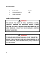
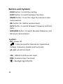
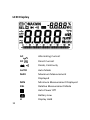
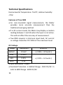
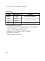
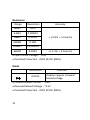
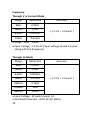
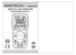
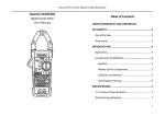
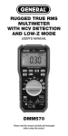
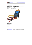
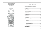
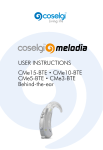
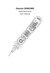
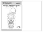
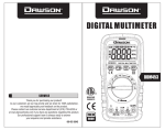
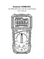
Dawson DDM230C True RMS Multimeter with Bar Graph Display User’s Manual Table of Contents LIMITED WARRANTY AND LIMITATION OF LIABILITY ................................................... 3 Out of the Box............................................. 3 Accessories ................................................. 4 Safety Information...................................... 4 Certification ................................................ 8 INTRODUCTION ........................................... 8 Overview ..................................................... 8 Components and Buttons ........................... 9 Components ............................................ 9 Buttons and Symbols ............................ 10 LCD Display ........................................... 11 USING THE METER ..................................... 12 Display Hold .............................................. 12 Switch between Modes ............................ 12 Relative Measurement ............................. 13 Max/Min Measurement ........................... 13 1 Switch between Functions ........................ 14 Backlight ................................................... 14 Auto Off .................................................... 14 NCV (Non-Contact Voltage Detector) ....... 14 DC and AC Voltage Measurement ............ 15 Resistance ............................................. 16 Continuity ................................................. 16 Diode ........................................................ 16 Capacitance .............................................. 17 Frequency and Duty Ratio ........................ 17 Current...................................................... 17 SPECIFICATIONS ........................................ 18 General Specifications .............................. 18 Technical Specifications ............................ 19 MAINTENANCE AND REPAIR ..................... 26 Battery Replacement ................................ 26 Test Leads Replacement ........................... 27 CONTACT DAWSON ................................... 27 FEATURES ...................................... Back Page 2 LIMITED WARRANTY AND LIMITATION OF LIABILITY This instrument from Dawson Tools Inc. will be free from defects in workmanship and material for three years from the date of original purchase. This warranty does not cover defects resulting from damage caused by the user such as drops, neglect, misuse, unauthorized alteration, usage outside of specified conditions, contamination, or improper repair/maintenance. To receive service on the instrument if it becomes necessary during the warranty period, contact your nearest Dawson authorized service center at (800) 898-6991 or visit www.DawsonTools.com to obtain a return authorization (within the US only). A return authorization is necessary before returning any instrument to Dawson; no service will be provided without a return authorization. The user is responsible for properly packing the unit and charges such as shipping, freight and insurance charges. The extent of Dawson's liability is limited solely to the repair/replacement of the instrument. The above warranty in its entirety is inclusive and no other warranties, written or oral, are expressed or implied. Out of the Box Check the Meter and accessories thoroughly before using the Meter. Contact your local distributor if the Meter or any components are damaged or malfunction. 3 Accessories Test Leads 9V 6F22 Battery User’s Manual 1 pair 1pc Safety Information WARNING TO REDUCE THE RISK OF FIRE, ELECTRICAL SHOCK, PRODUCT DAMAGE OR PERSONAL INJURY, PLEASE FOLLOW THE SAFETY INSTRUCTIONS DESCRIBED IN THE USER MANUAL. READ THE USER MANUALS BEFORE USING THE METER. WARNING TO ENSURE SAFE OPERATION AND LIFE OF THE METER, DO NOT PLACE THE METER IN ANY ENVIRONMENT WITH HIGH PRESSURE, HIGH TEMPERATURE, DUST, EXPLOSIVE GAS OR VAPOR. 4 5 Avoid shaking, dropping or any kind of impacts when using or transporting the Meter. To avoid electric shock or personal injury, repairs or servicing not covered in this manual should be performed only by qualified personnel. Avoid direct exposure to sunlight to ensure extended life of the Meter. Do not place Meter in a strong magnetic field; this may cause false readings. Use only the batteries indicated in the Technical Spec. Avoid exposing batteries to humidity. Replace batteries as soon as the low battery indicator appears. Please keep the original packing for future shipping purposes (ex. Calibration) After opening the box, check for any damage during delivery. Check the terminals every time before operating the Meter. Do not operate the Meter if the terminals are damaged or one or more functions are not working properly. Check the test leads before operation. Leads must be in good condition; check if leads are well covered by insulator, and if wires are not exposed. Use the original test leads included in the package for best performance and safety. If necessary, use the compatible leads with same specifications of the originals’. Safety Symbols on the Meter Important safety information, please refers to the user manual Earth ground Indicates compliance with requirements for double insulation Important Safety Information 6 Never use the Meter to measure voltages that might exceed 600V DC/AC above earth ground. In Manual Mode, if the circuit value is unknown, start the Meter at the maximum range and then adjust accordingly. 7 Always be careful when working with voltages above 60V DC or 30V AC RMS. Keep fingers behind the probe barriers while measuring. Never connect the Meter leads across a voltage source while the rotary switch is in the resistance, diode or continuity mode. Doing so can damage the Meter. Inspect test leads and probes for cracks, breaks or crazes on the insulation before using the Meter. Remove the leads from the circuit first before switching between functions. Do not power on the circuit when measuring resistance, capacitance or diodes. Do not measure the capacitance before the capacitors are discharged. Do not operate the Meter near explosive gas, vapor or under dust. Stop the operation if the Meter or test leads appeared damaged or do not function properly. Unless the battery cover and the Meter case are firmly closed, do not use the Meter. Repair or maintenance should be implemented by trained personnel. Certification CAT IV: This meter has meet IEC1010-1 standard with an overvoltage category (600V CAT IV) and pollution degree 2. The Meter is compiled to EMC requirements. Introduction Overview Dawson DDM230C is a portable, hand-held yet professional meter that features True RMS measurement display, AC/DC current, AC/DC voltage, Frequency, Capacitance, Resistance, Continuity, Duty Ratio, and Diode Testing. This Meter is easy to use even with one hand, suitable for professional users or amateurs, and ideal for school or home use. 8 Components and Buttons Components 1. NCV LED Indicator 2. LCD Display 3. Buttons 4. Function Rotary Switch 5. Input 6. Voltage Sensing Area. 9 Buttons and Symbols HOLD button: to hold the reading. FUNC button: to switch between functions. RANGE button: to set the range for manual or auto measurement. REL button: for relative measurement. Hz/% button: to switch between Frequency and Duty Ratio. MAX/MIN button: to switch between Maximum and Minimum measurement. Symbols: OFF: power off. : Input terminal for Resistance, Capacitance, Voltage, Frequency, Diodes and Continuity. μA, mA: μA and mA input. 10A : 600mA to 10A current input COM: Common Input Terminals. : Backlight light ON/OFF. 10 LCD Display AC Alternating Current DC Direct Current , Diode, Continuity AUTO Auto Mode MAX Maximum Measurement Displayed MIN Minimum Measurement Displayed REL Relative Measurement Mode Auto Power Off Battery Low H 11 Display Hold % Percentage(Duty Ratio) mV, V MilliVolt, Volt(Voltage) A Amp(Current) nF,μF, mF Nanofarads, Microfarads, Millifarads Ω, kΩ, MΩ Ohms, Kilohms, Megaohms Hz, kHz, MHz Hertz, Kilohertz, Megahertz NCV Non-Contact Voltage USB Mode Using the Meter Display Hold During measurement, press “HOLD” button to hold the current reading on the display. Press “HOLD” again to unlock the reading. Switch between Modes When using the rotary switch to switch between current, voltage, capacitance and frequency mode, the default range type is Auto. Press “RANGE” button to enter Manual mode. Each press increases the 12 measuring range and will return to minimum range after maximum has been reached. Hold “RANGE” for 1 second to switch back to Auto mode. If the Meter in in Max/Min mode. Press “RANGE” to return to Normal mode. Note: Manual mode is not allowed in frequency measurement. Relative Measurement Press “REL” button to enter Relative Measurement Mode. Reading = (current measurement – measurement when “REL” is pressed) Max/Min Measurement To Find Max/Min of the measurement, in any mode, press “MAX/MIN” to enter Maximum measurement and press again to enter Minimum measurement. Holding the button will go back to normal measurement and the Max/Min readings will be recorded. 13 Switch between Functions During Voltage or Current measuring, press “FUNC” button to switch between AC and DC measurements. When measuring Resistance, Diode or Continuity, press “FUNC” will switch between these modes. Backlight Press “ ” to turn on/off the display backlight. Auto Off If the Meter is not in use for 30 minutes, the Meter turns off automatically to conserve power. Press any button to turn the Meter back on. To disable Auto Off, hold “ FUNC” button when turning on the Meter. NCV (Non-Contact Voltage Detector) Turn the rotary switch to NCV mode, move the top of the Meter close to target. The Voltage sensing indicator will flash and buzz if the Meter senses a voltage greater then 110V AC. 14 WARNING EVEN THOUGH THERE IS NO INDICATION, VOLTAGE MAY STILL EXIST. THE MEASUREMENT MAY BE AFFECTED BY THE DESIGN OF THE OUTLET, TYPE OF INSULATION AND OTHER EXTERNAL FACTORS. NOTE: The voltage sensing indicator may turn on when a voltage is fed to the Meter. Other external interference (ex. Flashlight, motor) may trigger the NCV sensor. DC and AC Voltage Measurement Turn the rotary switch to Mode, connect the black lead to COM and the red lead to V input. Use the two leads to test the target. Measurement is shown on the display. In DC mode, the Meter also displays the polarity of red lead side input. Press “FUNC” button to switch between DC and AC voltage measuring. 15 NOTE : 660mV range is only accessible in Manual Mode. Resistance Turn the rotary switch to . Connect the black lead to input COM and the red lead to . Use both leads to test the target resistance and read the measurement from the display. Continuity Press “FUNC” during resistance measurement to switch to continuity test. Connect the black lead to input COM and the red lead to . Use both leads to test the target resistance; the Meter will buzz if the resistance is less than 50 ohms. Diode Press “FUNC” during continuity test to switch to diode test. Connect the black lead to input COM and the red lead to . Connect red lead to anode (+) and black to cathode (-); the Meter shows forward biased voltage. 16 Capacitance Turn the rotary switch to .Connect the black lead to COM and the red lead to . Use both leads to test the target capacitor and read off the capacitance from the meter. Frequency and Duty Ratio Turn the rotary switch to “Hz%”. Connect the black lead to COM and the red lead to Hz. Use both leads to test the target and read off both values from the Meter. Press “Hz%” to switch between frequency and duty ratio (%). Current Disconnect the target circuit from power source and discharge the circuit. Turn the rotary switch to appropriate mode (µA, mA or A). Connect the black lead to COM and the red lead to µA mA if the target current is less than 600mA; connect to 10A if the target current is between 600mA to 10A. Break the circuit and connect the leads across the broken circuit (Red to higher voltage, black to the lower). Power the circuit and read the measurement from the display. If the Meter displays “OL” (overload) switch the rotary switch to a higher range. 17 Specifications General Specifications Full time surge protection. Maximum Voltage range between target and ground: 600V DC or AC. Maximum working height: 2000m. Maximum display number: 6599. Auto Polarity Indication, ‘-’indicates negative. Overload Indication: ‘0L’or ‘-0L’. Sampling Time: 0.4 seconds. 1 second on current measurement. Units Display: Display functions and units. Auto Power Off: 30 minutes Input Power: 9V DC Battery Type: 6F22 Low Battery Indication: LCD display Working Environment Temp: 32°F~104°F (0°C~40°C) Storage Temperature: 14°F ~122°F (-10°C~50°C) Size: 7 x 3.4 x 2 in (180×86×52mm) Weight: 8.8oz ~(250g) exclude battery 18 Technical Specifications Environmental Temperature: 749°F, relative humidity: <75% Features of True RMS For non-sinusoidal signal measurement, the Meter provides more accurate measurement than the traditional averaging method. If in AC current mode, the Meter may display a random reading between 1 and 50 when the input is not active. This will not affect the accuracy of measurement. True RMS requires a minimum input level, AC current or voltage should be 2%~100% of the maximum level. DC Voltage Range Resolution Accuracy 660mV 0.1mV ( 0.8% + 3 Counts ) 6.6V 0.001V 66V 0.01V 600V 0.1V ( 0.5% + 5 Counts ) Input Resistance : 10M Overload Protection: In 660mV Range : 250V DC/AC. In 6.6V to 600V Range : 600V DC/AC 19 Maximum Input Voltage : 600V DC AC Voltage Range Resolution Accuracy 660mV 0.1mV ( 1.5% + 5 Counts ) 6.6V 0.001V 66V 0.01V 600V 0.1V ( 1.2% + 5 Counts ) ( 1.5% + 5 Counts ) Input Resistance : 10M Overload Protection: In 660mV Range : 250V DC/AC. In 6.6V to 600V Range : 600V DC/AC Maximum Input Voltage : 600V AC (RMS) Frequency : 50~60 Hz Measurement: True RMS 20 Resistance Range Resolution 660 0.1 6.6k 0.001k 66k 0.01k 660k 0.1k 6.6M 0.001Mk 66M 0.1M Accuracy ( 0.8% + 5 Counts) ( 1.5% + 5 Counts ) Open Circuit Voltage : ~0.4V Overload Protection : 250V DC/AC (RMS) Diode Resolution 0.001V Function Displays approx. forward biased voltage Forward Biased Current : ~1mA Reversed Biased Voltage : ~3.3V Overload Protection : 250V DC/AC (RMS) 21 Capacitance Range Resolution Accuracy 6.6nF 0.001nF ( 4% + 5 Counts ) 66nF 0.01nF 660nF 0.1nF 6.6F 0.01F 66F 0.01F 660F 0.1F 6.6mF 0.001mF 66mF 0.01mF ( 5% + 3 Counts ) ( 4% + 5 Counts ) Overload Protection : 250V DC/AC (RMS) Continuity Resolution 0. 1 Function The Meter buzz when the target resistance is smaller then 30 Open Circuit Voltage : ~1.2V Overload Protection : 250V DC/AC (RMS) 22 Frequency Through V or Current Mode Range Resolution 66Hz 0.01Hz 660Hz 0.1Hz 6.6kHz 0.001kHz 10kHz 0.01kHz Accuracy ( 1.5% + 5 Counts ) Range : 10Hz ~ 10kHz Input Voltage : ≥ 0.2V AC (Input voltage should increase along with the frequency) Through Hz Mode Range Resolution 66Hz 0.01Hz 660Hz 0.1Hz 6.6kHz 0.001kHz 66kHz 0.01kHz 660kHz 0.1kHz 6.6MHz 1kHz 66MHz 10kHz Accuracy ( 1.5% + 5 Counts ) Input Voltage : 3V peak to peak AC Overload Protection : 250V DC/AC (RMS) 23 Duty Ratio Range Resolution Accuracy 10 - 95% 0.1% 2.0% Open Circuit Voltage : 1.2V Overload Protection : 250V DC/AC (RMS) DC Current Range Resolution 660A 0.1A 6600A 1A 66mA 10A 660mA 100A 10A 10mA Accuracy ( 1.0% + 5 Counts ) ( 2.0 % + 5 Counts ) Overload Protection: In A and mA range, Fuse: FF600mA/1000V. In A Mode: Fuse: FF10A/500V. When the target current is larger than 5A, do not continue the measurement for more than 10 seconds. Pause for 1 minute after measuring. 24 AC Current Range Resolution 660A 0.1A 6600A 1A 66mA 10A 660mA 100A 10A 10mA Accuracy ( 1.5% + 5 Counts ) ( 3.0% + 5 Counts ) Overload Protection: In A and mA range, Fuse: FF600mA/1000V. In A Mode: Fuse: FF10A/500V. When the target current is larger than 5A, do not continue the measurement for more than 10 sec. Pause for 1 minute after the measuring. Frequency : 50~60 Hz Measurement: True RMS 25 Maintenance and Repair Battery Replacement WARNING TO AVOID ELECTRICAL SHOCK, PRODUCT DAMAGE OR PERSONAL INJURY, REMOVE TEST LEADS BEFORE OPENNING BATTERY COVER. Replace batteries when the battery indicator“ ”is on. Remove the battery cover and replace a new battery. 26 Test Leads Replacement WARNING REPLACE TEST LEADS WITH IDENTICAL OR COMPATIBLE LEADS. LEAD SPEC:1000V 10A. Replace new leads if the current leads worn. Contact Dawson Dawson Tools, Inc. 1142 S. Diamond Bar Blvd., #858 Diamond Bar, CA 91765 Phone: (310) 728-6220 www.DawsonTools.com Do not recycle 27 (Back Page) Features 28 LCD Display Auto Ranging Relative Measurement Non-Contact Voltage Detector True RMS Diode Test Continuity Buzzer MAX/MIN Display Data Hold Auto Power Off Low Battery Back Light