1
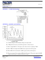
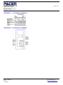
1450 First Ave.
Chippewa Falls, WI 54729
(800) 283-1141 or (715) 723-1141
Fax: (715) 723-7890
[email protected]
Page 1 of 10
Model DA40T
User Manual
DA40T User Manual
Rev 1.0
11-Aug-2007
Pacer Instruments, Inc
www.pacer-instruments.com
Phone: 1-800-283-1141
1450 First Ave.
Chippewa Falls, WI 54729
(800) 283-1141 or (715) 723-1141
Fax: (715) 723-7890
[email protected]
Page 2 of 10
Warranty
This product is fully warranted against defective materials and/or workmanship for a period of one year
after purchase, provided it was not improperly used. For your protection, please use this product as soon as
possible. If returned, it must be securely wrapped, sent prepaid and insured to:
Pacer Industries, Inc.
1450 First Avenue
Chippewa Falls, WI 54729
PH: 715-723-1141
FX: 715-723-7890
Please include a note with name, address, telephone number and description of the problem. Although we
provide assistance on Pacer products both personally and through our literature, it is still the total
responsibility of the customer to determine the suitability of the product for use in their application.
This manual is provided by Pacer Industries without any kind of warranty. Precautions have been taken in
accurately preparing this manual; however, we neither assume responsibility for any omissions or errors that
may appear nor assume liability for any damages that result from the use of the products in accordance with
the information contained in the manual.
DA40T User Manual
Rev 1.0
11-Aug-2007
Pacer Instruments, Inc
www.pacer-instruments.com
Phone: 1-800-283-1141
1450 First Ave.
Chippewa Falls, WI 54729
(800) 283-1141 or (715) 723-1141
Fax: (715) 723-7890
[email protected]
Page 3 of 10
INTRODUCTION
Pacer’s model DA40T digital thermometer-anemometer is a versatile instrument for measuring air velocity and
temperature of airflow from HVAC ducts or process air flow.
The heavy, all metal (except electronics) probe can be used for airstreams which have a wide range of humidity,
temperature and contaminants without compromising accuracy. Temperature sensor is a Platinum Resistance
Element (RTD).
Features include choice of probe diameters, custom cable lengths, tolerance of temperatures up to 210˚F
(98.9˚C) at the probe, and durability. Optional special-purpose temperature-only probes may be purchased from
factory.
SECTION 1 - SPECIFICATIONS
Range:
APT275 probe:
40 – 7800 FPM (0.2 - 40.0 MPS)
APT100 probe:
60 – 6800 FPM (0.3 – 35.0 MPS)
Temperature – Either velocity probe:
-22º to 212ºF (-30º to 100ºC)
Temperature – Optional temperature-only probes:
-139º to 392.0ºF (-95º to 200.0ºC)
Accuracy:
Air Velocity:
±1.0% of reading ±1 digit
Temperature:
±0.3% of Reading ±1 digit
Resolution:
Air Velocity:
1 FPM or 0.01 MPS
Temperature:
0.1ºF or ºC (1ºF below -99.9ºF)
Operating Temperature:
Instrument:
32 to 125ºF (0 to 50ºC)
Probes:
-4º to 210ºF (-20º to 98.9ºC)
Power Supply:
2 AA alkaline batteries, E91 Eveready or equivalent
Battery Life:
Approximately 200 hours
Battery check:
Automatic low battery display
Display:
0.5” LCD, 4 digits
Weight:
8 ounces with batteries
Dimensions:
Instrument:
7.1” x 3.0” x 0.8”
APT275 probe:
2 ¾” diameter
APT100 probe:
1” diameter
DA40T User Manual
Rev 1.0
11-Aug-2007
Pacer Instruments, Inc
www.pacer-instruments.com
Phone: 1-800-283-1141
1450 First Ave.
Chippewa Falls, WI 54729
(800) 283-1141 or (715) 723-1141
Fax: (715) 723-7890
[email protected]
Page 4 of 10
Options:
Model CG-4 charger:
PN 3303 (with 4 NiMH batteries)
Additional probe:
APT100 (1”) or APT275 (2 ¾”)
Cable longer than 5’:
Model 3836, specify length
Extra extension rod:
PN 5001 rigid, PN 5002 flexible
Special-purpose temperature probes:
PT201T:
PN 6332 GP immersion probe
PT202T:
PN 6334 air temperature probe
PT203T:
PN 6335 surface probe
Included:
1 piece:
probe head, choice of APT100 or APT275
3 pieces:
PN 5001 rigid extension rod
1 piece:
PN 5002 flexible extension rod
1 piece:
PN 3836 5 ft. connection cable
(attached to the APT100 probe)
2 pieces:
AA 1.5V alkaline batteries
1 piece:
PN 6004 hard-shell carrying case
1 piece:
Operation manual
DA40T User Manual
Rev 1.0
11-Aug-2007
Pacer Instruments, Inc
www.pacer-instruments.com
Phone: 1-800-283-1141
1450 First Ave.
Chippewa Falls, WI 54729
(800) 283-1141 or (715) 723-1141
Fax: (715) 723-7890
[email protected]
Page 5 of 10
SECTION 2 – SWITCH FUNCTIONS
ON/OFF
Pressing “ON/OFF” key switches unit ON. Pressing the key a second time turns it OFF.
FPM/MPS
Pressing “FPM/MPS” key toggles unit from FPM (1 FPM resolution) to MPS (0.01 MPS
resolution).
ºF/ºC
Pressing the “ºF/ºC” key displays temperature in degrees Fahrenheit (ºF); pressing key a second
time changes display to Celsius (ºC).
2 SEC.
Pressing “2 SEC.” key sets measurement period to two seconds. The display will show “2 SEC.”,
then a measurement value. It will update every two seconds with average of the preceding two
seconds.
16 SEC.
Pressing “16 SEC.” key sets measurement period to sixteen seconds. The display will show “16
S” for 16 sec., then a measurement value. It will update every two seconds with average of the
preceding sixteen seconds.
MAX/MIN
Pressing “MAX/MIN” key displays the highest reading since turn-on for air velocity or
temperature. Pressing key a second time will display lowest reading since turn-on.
Air Velocity: In “2 SEC.” mode display reads “H 2” (“L 2”) followed by reading. In “16 SEC.”
mode display reads “H 16” (“L 16”) followed by reading.
Temperature: Maximum is indicated by “H tP” followed by reading. Minimum is indicated by
“L tP” followed by reading.
Clear the internal memory by turning unit OFF. Clear the “MAX/MIN” mode by pressing any
other key (except “HOLD”). See APPENDIX B for description of algorithm that determines
MAX and MIN.
DA40T User Manual
Rev 1.0
11-Aug-2007
Pacer Instruments, Inc
www.pacer-instruments.com
Phone: 1-800-283-1141
1450 First Ave.
Chippewa Falls, WI 54729
(800) 283-1141 or (715) 723-1141
Fax: (715) 723-7890
[email protected]
Page 6 of 10
HOLD/RESET Pressing “HOLD/RESET” key will freeze the reading on the display; “HOLD” is displayed
and the reading is held. Pressing “HOLD/RESET” key a second time frees the display.
SECTION 3 – OPERATION
NOTE: Unit should be “OFF” before changing batteries or attaching probe.
1) Remove battery compartment lid and insert batteries; replace lid (see APPENDIX D).
2) Attach the probe cable by aligning the keyway(s), inserting connector(s) and turning collar(s) to
tighten (see APPENDIX A for wiring diagram).
3) Press the “ON/OFF” key to turn unit ON. The display will show all its elements (see
APPENDIX C) followed by the remaining battery capacity (“bA85” means the battery is at 85%
capacity) followed by “2.75” or “1.00” indicating that the APT275 or APT100 probe,
respectively, is attached.
Replace batteries if symbol shows during usage.
4) Press “FPM/MPS” key, if needed, to display desired units. Place probe in the air stream with the
axis or direction arrow (if present) in the direction of the airflow. To calculate CFM see
APPENDIX E.
5) To correctly measure the air velocity from a large duct, set unit to “16 SEC.” mode and move
probe about the area of the opening. After 16 seconds, the unit will display the velocity for the
preceding 16 seconds, updating after that every 2 seconds by adding the latest 2 second
measurement and dropping the oldest 2 second measurement.
6) Press “ºF/ºC” key to display temperature in ºF; press again to display in ºC. Place probe in area to
be measured. See APPENDIX F if “E-xx” is displayed.
7) To get maximum readings since turn-on, press “MAX/MIN” key; to get minimum readings,
press “MAX/MIN” key a second time. For explanation of the displayed views, see “MAX/MIN”
paragraph in SECTION 2, also see APPENDIX B.
8) To HOLD the displayed reading, press the “HOLD/RESET” key. Press key again to clear the
HOLD condition.
DA40T User Manual
Rev 1.0
11-Aug-2007
Pacer Instruments, Inc
www.pacer-instruments.com
Phone: 1-800-283-1141
1450 First Ave.
Chippewa Falls, WI 54729
(800) 283-1141 or (715) 723-1141
Fax: (715) 723-7890
[email protected]
Page 7 of 10
APPENDIX A – CONNECTOR DIAGRAM
APPENDIX B – MAX/MIN CALCULATIONS
A) 1st MAX reading; also first minimum reading, to be replaced at B.
B) 1st MIN at B is the lowest yet and will be registered as velocity increases.
C) This 2nd, higher MAX at C will register as the velocity decreases, replacing 1st MAX.
D) This 2nd MIN at D is higher than the MIN already registered and will be ignored.
E) This 4th MIN at E is lower than the 1st MIN, registered at B, and will replace it.
F) The zero crossing at F does not form a MIN and will be ignored. This protects against false MIN
readings when the probe is withdrawn from the air stream.
DA40T User Manual
Rev 1.0
11-Aug-2007
Pacer Instruments, Inc
www.pacer-instruments.com
Phone: 1-800-283-1141
1450 First Ave.
Chippewa Falls, WI 54729
(800) 283-1141 or (715) 723-1141
Fax: (715) 723-7890
[email protected]
Page 8 of 10
APPENDIX C – LCD DISPLAY SYMBOLS
APPENDIX D – CHANGING BATTERIES
DA40T User Manual
Rev 1.0
11-Aug-2007
Pacer Instruments, Inc
www.pacer-instruments.com
Phone: 1-800-283-1141
1450 First Ave.
Chippewa Falls, WI 54729
(800) 283-1141 or (715) 723-1141
Fax: (715) 723-7890
[email protected]
Page 9 of 10
APPENDIX E – AIRFLOW VOLUME CALCULATIONS
Theory:
To calculate cubic feet per minute (CFM) from a measured air velocity (FPM), you need the
calculated cross-sectional area of the airflow stream:
Volume Flow (CFM) = Velocity (FPM) X Area (sq ft).
In rectangular ductwork this cross sectional area equals the Width times the Height.
W x H=A (cross-sectional area)
In circular ductwork this cross section area equals the radius squared times π (3.14).
R x R x 3.14=A (cross-sectional area)
To convert an area calculated in square inches to an area calculated in square feet (which is
required for the Volume Flow equation above) divide by 144: (area in sq in.)/144 = (area in sq
ft.).
Example:
Step 1:
Step 2:
Step 3:
The air duct is rectangular, the width is 24 in. and the height is 12 in. The air velocity reading
through the duct is 450 FPM. Calculate the Volume Flow.
Cross-sectional area = 24 in. x 12 in. = 288 sq in.
288 sq in /144 = 2 sq ft.
Volume flow = Air Velocity x Area, therefore, Volume flow rate = 450 FPM x 2 sq ft. = 900
CFM.
APPENDIX F – ERROR CODES
E-08
Temperature lower than -95.0ºC or -139ºF
E-09
Temperature higher than 205.0ºC or 401.0ºF
DA40T User Manual
Rev 1.0
11-Aug-2007
Pacer Instruments, Inc
www.pacer-instruments.com
Phone: 1-800-283-1141
1450 First Ave.
Chippewa Falls, WI 54729
(800) 283-1141 or (715) 723-1141
Fax: (715) 723-7890
[email protected]
Page 10 of 10
Notes:
DA40T User Manual
Rev 1.0
11-Aug-2007
Pacer Instruments, Inc
www.pacer-instruments.com
Phone: 1-800-283-1141


![PathoDx Strep Grouping Control Antigens [FR]](http://vs1.manualzilla.com/store/data/006414297_1-a8d67962adf72e2f12fa8d3e0fc73180-150x150.png)


![PathoDx Strep D Grouping and Control Latexes [FR]](http://vs1.manualzilla.com/store/data/006427765_1-0055511004fa7899d2e5aa062345d9c9-150x150.png)