1
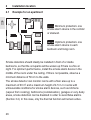
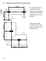
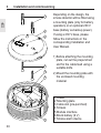
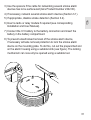
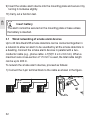
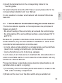
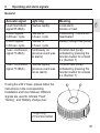
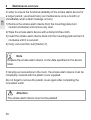
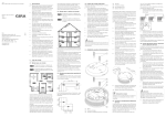
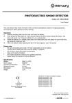
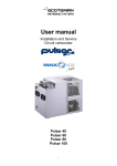
FITT-10210
Issue 1
Product features
• Battery-operated, combined smoke alarm device and thermal detector
(maximum and differential function) for the protection of residential
buildings, apartments or rooms with similar purpose in accordance with
DIN 14676
• Smoke detection can be disabled for rooms where the ambient
conditions are not favourable for the smoke alarm device, such as
kitchens (vapour from cooking)
• Automatic selftest of smoke evaluation with impurities indicator
• When dark, up to 12 hours delayed indication of battery replacement
display or technical fault
• Wired networking of up to 40 smoke detectors
• Loud, intermittent warning tone, minimum 85 dB (A)
• Battery replacement display
• Soiling/fault display
• Built-in button for function test
• Battery compartment interlock: if the smoke detector does not have
a battery fitted, then it is not possible to lock it into place in the mounting
plate or 230 V base.
• 1 module interface for fitting one of the optionally available modules; the
network terminals remain available for use
• Polarity reversal protection: The unit cannot be destroyed due to
incorrect battery connection
• Can be retrofitted with 230 V base for Smoke alarm device Dual/VdS
(product no. 2331 02)
25
GB
1
Installation location
2.1
Example for an apartment
GB
2
Minimum protection: one
smoke alarm device in the corridor
or stairwell.
Optimum protection: one
smoke alarm device in each
bedroom and living room.
Smoke detectors should ideally be installed in front of or inside
bedrooms, so that the occupants will be woken up if there is a fire at
night. For optimum performance, install the smoke alarm device in the
middle of the room under the ceiling. If this is not possible, observe a
minimum distance of 50 cm to the walls.
The smoke detector can monitor rooms with a floor area up to a
maximum of 60 m2 and a maximum height of 4.5 m. In rooms with
unfavourable conditions for smoke alarm devices, such as kitchens
(vapour from cooking), bathrooms (condensation), garages or very dusty
areas, smoke detection can be disabled in order to avoid false alarms
(Section 3.2). In this case, only the thermal function will remain active.
26
Example for a residential building
Minimum protection: one
smoke alarm device in the corridor
or stairwell of each floor.
Optimum protection: one
smoke alarm device in each
bedroom, living room and
basement room.
In buildings with several storeys, install at least one smoke alarm device
in the corridor of each storey.
Use several networked smoke alarm devices in larger houses in order
to cover the entire living area. If smoke is detected by a smoke alarm
device, it triggers an alarm and activates all the connected smoke alarm
devices which then also emit an alarm. This ensures, for example, that
you are woken during the night in your bedroom by your networked
smoke alarm device if the smoke alarm device in the basement detects
smoke.
The same requirements apply to the installation of individual smoke
alarm devices in rooms and the use of the thermal detection function
as those described for installation in an apartment (Section 2.1).
27
GB
2.2
2.3
Examples for particular room geometries
GB
In L-shaped rooms or
corridors the smoke
alarm devices should be
installed on the centred
intersections of the two
sections.
In the case of large
L-shaped rooms, each
section is regarded as a
separate room.
28
2.4
Unsuitable installation locations
In order to avoid false alarms, do not install the smoke alarm device:
GB
• with active smoke detection in rooms in which a lot of steam, dust or
smoke occur under normal conditions (Section 3.2)
• near fireplaces or open fires
• directly on a metal surface
• less than 1 m away from air conditioning units and ventilation shafts, as
the air flow may prevent the smoke and/or heat from reaching the alarm
• at least 50 cm away from electrical ballasts, low voltage transformers,
fluorescent lights and energy saving lights
• in rooms which are higher than 4.5 m
• less than 30 cm away from the roof apex
• only in rooms where the temperature does not fall below -5 °C or rise
above +50 °C
• less than 6 m away from hot-air vents
Attention
Do not mount the smoke alarm device in a vertical position on a wall.
This can cause it to malfunction.
29
3
Installation and commissioning
GB
1
2
3
4
5
6
7
30
Depending on the design, the
smoke detector will be fitted using
a mounting plate (only for battery
operation) or an optional 230 V
base (battery as backup power).
If using a 230 V base, please
follow the instructions in the
corresponding Installation and
User Manual.
1) Before attaching the mounting
plate, cut out the prepunched
slot for the cable feed using a
suitable knife.
2) Mount the mounting plate with
the enclosed mounting
material.
1 Dowel
2 Mounting plate
3 Cable slot (pre-punched)
4 Screws
5 Module interface
6 Block battery (9 V)
7 Smoke alarm device
3) Use the spacers if the cable for networking several smoke alarm
devices has to be surface-laid (Gira Product Number 2342 00).
4) If necessary, network several smoke alarm devices (Section 3.1).
GB
5) If appropriate, disable smoke detection (Section 3.2).
6) Insert a radio or relay module if required (see corresponding
Installation and User Manual).
7) Connect the 9 V battery to the battery connection and insert the
battery in the battery compartment.
8) To prevent unauthorised removal of the smoke alarm device,
if necessary activate removal protection to lock the smoke alarm
device on the mounting plate. To do this, cut out the prepunched slot
on the alarm housing using a suitable knife (see figure). The locking
mechanism can now only be opened using a suitable tool.
31
9) Insert the smoke alarm device into the mounting plate and secure it by
turning it clockwise slightly.
GB
10) Carry out a function test.
Insert battery
The alarm cannot be secured on the mounting plate or base unless
the battery is inserted.
3.1
Wired networking of smoke alarm devices
Up to 40 Gira Dual/VdS smoke detectors can be connected together in
a network to allow an alarm to be sounded by all the smoke detectors in
a dwelling. Connect the smoke alarm devices in parallel with a twoconductor cable (e.g., phone cable: J-Y(St)Y 2 x 2 x 0.6 mm). When a
maximum wire cross-section of 1.5 mm2 is used, the total cable length
can be up to 400 m.
To network the smoke alarm devices, proceed as follows:
1) Connect the 3-pin terminal block to the cable as shown in the figure.
N
Signal
N
Detector 1
32
N
Detector 2
N
Detector n
2) Insert the terminal block in the corresponding holder in the
mounting plate.
For wired networks where the 230 V base is used, please refer to the
corresponding Installation and User Manual.
3.2
GB
It is not possible to create a wired network with modular/VdS smoke
detectors.
Thermal detector function/deactivating the smoke detector
The thermal detector operates on the temperature rise principle and
triggers an alarm if:
• the rate of heating of the surrounding air exceeds the normal range,
• the temperature of the surroundings reaches a value between 54 °C
and 70 °C.
Because it is possible to deactivate smoke detection on the Dual/VdS
smoke detectors, they are also suitable for installation in areas where
conventional smoke detectors cannot be used.
• in rooms where smoke detection is not appropriate, such as kitchens
(steam from cooking) and bathrooms (condensation),
• rooms where there is a lot of dust (e.g. garages).
In such cases, it can make sense to deactivate the smoke detection in
order to avoid false alarms. In such cases the smoke detector will only
function as a thermal detector.
Proceed as follows to deactivate smoke detection (deactivation is not
permitted while an alarm is ongoing):
1) If necessary, remove the battery as the slide switch is located on the
PCB under the battery compartment.
2) Break out the cover over the slide switch using a suitable tool.
33
GB
Attention
Breaking out the slide switch cover will invalidate the CE conformity of
the smoke detector in accordance with EN14604 and invalidate the
German Association of Property Insurers (VdS) Approval.
3) Set both slide switches to the
“ON” position (see figure) to
deactivate smoke detection.
4) Reconnect the 9 V block battery to the battery connector and insert the
battery into the battery holder.
5) Carry out a function test (Section 7).
34
4
Operating and alarm signals
Acoustic signal
Loud intermittent
signal 85 dB(A)
8 short signals
in 60-sec. cycle
2 short signals
in 60-sec. cycle
1-sec. continuous
signal 73 dB(A)
1-sec. continuous
signal 73 dB(A)
Light ring
Flashes rapidly
Flashes 8x
in 8-sec. cycle
Flashes 1x
in 5-sec. cycle
Continously on
(previous event was
an alarm)
Flashes rapidly
(previous event was
not an alarm)
If using the 230 V base, please follow the
instructions in the corresponding
Installation and User Manual. Different
signals are used to indicate “Fault”,
“Soiling”, and “Battery change due”.
Meaning
Local alarm Smoke or heat
Fault/soiling - Cannot be
deactivated
Battery change due (local)
Function test (local),
activated by pressing the
function button for at least
4 s (Section 7)
Function test (local),
activated by pressing the
function button for at least
4 s (Section 7)
2
1
1 Light ring
2 Function button
35
GB
General
GB
For wired or radio-networked (if equipped with optional radio
module) smoke alarm devices
The signals generated by the smoke alarm device that triggers the alarm
are as described above. The other smoke alarm devices will also emit
the following signals:
Acoustic signal
Loud intermittent
signal 85 dB(A)
2 short signals
in 60-sec. cycle
Light ring
-
1-sec. continuous
alarm signal
73 dB(A) followed
by 2 s pause
-
5
-
Meaning
Alarm at networked smoke
detectors - smoke or heat
only for wireless networks:
Battery change due
(remote signal)
Function test (remote signal),
activated by pressing the function
button for at least 4 s (Section 7)
Battery test – Changing the battery
The smoke detector is powered from a 9 V block battery (if a 230 V base
is used, then only when there is an interruption to the mains power). The
battery test automatically checks the supply voltage at regular intervals. If
the battery voltage drops below a defined level, the smoke alarm device
signals for 30 days that the battery has to be replaced. The smoke alarm
device is completely functional during this period.
36
To replace the battery, proceed as follows:
1) To do this, release the locking mechanism with a screwdriver and turn
the smoke detector anticlockwise.
GB
2) Remove the old battery from the compartment and disconnect the
connector from the battery connection.
3) Connect the new 9 V battery to the battery connection and insert the
battery in the battery compartment.
4) Reinsert the smoke detector into the mounting plate or 230 V base
and lock in place by turning gently clockwise.
Insert battery
The smoke alarm device cannot be secured on the mounting plate or
base unless the battery is inserted.
5) Carry out a function test.
Only replace the old battery with a new battery of the same
type.
Dispose of the old battery in an environmentally-friendly way.
37
6
Maintenance and care
GB
In order to ensure the functional reliability of the smoke alarm device for
a longer period, you should carry out maintenance once a month (or
immediately when a fault message occurs):
1) Remove the smoke alarm device from the mounting plate (turn
counter-clockwise) and remove any dust.
2) Wipe the smoke alarm device with a damp lint-free cloth.
3) Insert the smoke alarm device back into the mounting plate and turn it
clockwise until it is secured.
4) Carry out a function test (Section 7).
Note
Replace the smoke alarm device on the date specified on the device
label.
If carrying out renovations in the room, the smoke alarm device must be
completely covered with the plastic cover supplied.
Do not forget to remove the plastic cover again after completing the
renovation work!
Attention
The smoke alarm device must not be painted!
38
7
Function test
Carry out the function test once a month and especially after long periods
of absence:
1) Press the function button for at least 4 seconds:
• If an audible signal is emitted following a short acknowledgement
sound and the light ring comes on (Section 4), then the smoke alarm
device is operating correctly.
• If no signal is emitted, replace the battery.
2) Then carry out the function test again. If a signal is still not emitted,
then the smoke detector is faulty and must be replaced.
3) Stop the function test by pressing the function button until the
acknowledgement signal is heard.
If a function test is carried out on wired or radio-networked smoke alarm
devices, all the connected smoke alarm devices emit an acoustic alarm.
If this does not occur, please check the batteries of all the smoke alarm
devices and the connections and state of the network cables.
39
GB
When carrying out a manual test, the smoke alarm device emits a
muffled signal. However you should still prewarn neighbours. Stay at
least 50 cm away from the smoke alarm device during a function test.
8
Manual suppression of signals
8.1
Suppressing the smoke detection alarm
GB
Smoke detection can be deactivated for 15 minutes:
• as a preventative measure to suppress an unwanted alarm when
carrying out activities that generate dust (sweeping a dusty room,
sweeping the chimney, etc.),
• to shut off the alarm if you detect non-hazardous smoke.
To do this, press the function button briefly (< 3 seconds) until a short
acknowledgement signal is heard and then muted again. The light ring
now flashes every 2 seconds
Note
Thermal detection is still active.
8.2
Suppressing the event display
A photovoltaic cell is used to suppress the “Detection head dirty” and
“Battery change due” warnings (Section 4) for up to 12 h during hours of
darkness. This has no influence on the alarm functionality provided by
the smoke detector.
If the “Replace battery” or “Fault/soiling” message occurs at an
inopportune time, it can be deferred by 8 hours each day for a maximum
of 7 days. To do this, press the function button briefly, until the first signal
tone is muted.
However, remove the source of the fault as soon as possible.
Please contact your installer to rectify cause of the problem.
40
Technical specifications
Nominal voltage:
9 V DC
Battery:
- 9 V block alkaline, type: DURACELL
PLUS/6LR61.
Lifetime approx. 5 years,
with radio module approx. 2 years.
- 9 V block lithium, type:
ULTRALIFE/U9VL-J.
Lifetime approx. 10 years,
with radio module approx. 5 years.
Battery failure signal:
60-sec. cycle, 30 days
Optical indication:
Light ring red
Acoustic alarm indication:
piezo primary detector: Intermittent
Volume:
Min. 85 dB (A) at 3 m
Housing dimensions:
125 x 48 mm (Ø x H)
Plastic material:
PC+ASA
Operating temperature:
-5 °C to +50 °C
Storage temperature:
-20°C to +65°C
Weight (without battery):
Approx. 120 g
Degree of protection:
IP42
VdS approval:
See rating plate on smoke detector
41
GB
9
10
CE declaration of conformity
GB
Please note that CE conformance in accordance with EN14604 is only
valid if smoke detection is not deactivated (Section 3.2).
09
0786-CPD-20896
VdS approval number: G209202
EN14604:2005
Smoke alarm device Dual/VdS
Giersiepen GmbH & Co. KG
Dahlienstraße 12
42477 Radevormwald, Germany
42
11
Warranty
Please send the unit postage free with a description of the defect to our
central customer service via your specialised dealer:
Gira
Giersiepen GmbH & Co. KG
Service Center
Dahlienstraße 12
42477 Radevormwald
Deutschland
43
GB
We provide a warranty as provided for by law.