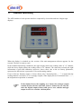
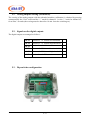
1
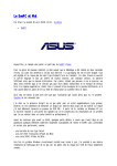
ASA-RT srl -- Strada del Lionetto, 16/a – 10146 Torino – ITALY
Tel: +39 011 796
5360884
333r.a..
r.a..−−Fax:
Fax:+39
+39011
011712
19835705
339
E_mail: [email protected] − Url: www.asa-rt.com
ADX
Torque measurement unit
User’s Manual
Ver. 2.10
(From FW 1.20 on)
1/1
1.
2.
Introduction..................................................................................................................................3
Installation and diagnostics..........................................................................................................4
2.1.
Security instructions.............................................................................................................4
2.2.
Instructions for the electromagnetic compatibility ..............................................................4
2.3.
Connections to earth.............................................................................................................4
2.4.
Cables shielding ...................................................................................................................5
3. Technical characteristics ..............................................................................................................6
4. Electrical connection....................................................................................................................7
5. Standard functioning ....................................................................................................................8
5.1.
Analog outputs zeroing (calibration) ...................................................................................9
5.2.
Signals on the digital outputs ...............................................................................................9
5.3.
Dip-switches configuration ..................................................................................................9
6. Advanced functioning ................................................................................................................11
6.1.
Parameters ..........................................................................................................................11
6.2.
Calibration of the reading gain...........................................................................................14
6.3.
Filter on the measurement..................................................................................................14
6.4.
Analog output full scale .....................................................................................................14
6.5.
Thresholds outputs handling ..............................................................................................15
2/2
1.
Introduction
ADX is a contactless system to measure the torque on rotating shafts and the force on rotating
systems. Through a transformer, a magnetic coupling between a stator and one or two rotor/s,
supplies power to one or two electric card/s, solidly placed with the rotors, to read the strain gages
bridges.
Rotor
Stator
Link “A”
Acquisition
card
Example :
Torque
measurement on
rotating shafts
Link “B”
Rotor
As regards the torque measurement on rotating shafts, each of them is instrumented with a complete
strain gages bridge and an acquisition card, with 24 bit ADC and a winding which acts as rotor.
If the ADX unit is used to measure the force on a rotating system, it will be supplied with an
acquisition card built-in the load cell body, suitable to carry out the measurement in a rotating
environment.
The stator of the transformer and the ADX-F management unit are placed on the fixed side of the
system.
ADX-F
Stator
All operating parameters of the unit can be programmed through the key-board and the display :
zero, gain (full scale in engineering unit), pass-band of the filter on the signal, etc.; in conditions of
standard functioning, the torque measurement of each shaft is displayed, according to the present
parameters.
Moreover, the unit has : digital I/O to be used for the remote zeroing and torque supervision
(outputs of operative channel and threshold alarms); analog outputs in tension or current; optionally,
the unit can be supplied with CANopen or Profibus interfaces.
3/3
2.
Installation and diagnostics
2.1. Security instructions
In order to have an installation in security conditions, it is necessary to
follow, besides the existing regulations, some simple rules:
•
•
!
•
•
•
All metallic parts of the plant must be connected to earth.
Control the external devices related to security before effecting the
plant working process check.
Test and maintenance of the plant must always be done by
qualified staff.
Before starting the system, make sure that it won’t cause
dangerous situations for people and things and for the machine
itself.
Before changing any parameter, check the correctness of the
parameter itself and value which could be the real effect of this
change.
2.2. Instructions for the electromagnetic compatibility
The electromagnetic noises (EMI) can cause the bad functioning of this or other devices located
nearby, compromising the plant working. Therefore, it is necessary, during the installation, to take
all precautions to limit the above mentioned noises produced by parts constituting the plant itself.
A correct connection of all devices to earth reduces the problems caused by EMI; in particular, it is
important to carefully follow the regulations indicated in the here-under paragraphs.
2.3. Connections to earth
Connect to earth all metallic parts of the units constituting the plant.
Avoid serial connection to earth, but effect single connections of each units to the main earth.
The main earth bar must be connected to the metallic cabinet and to the general earth well.
4/4
2.4. Cables shielding
The cables corresponding to the analog signals must be shielded.
To avoid the shield having currents circulation which could make it useless or even a noising
source, the equipotentiality of the masses of the plant-cabinet system must be assured by special
connections, conveniently sized.
The connections of the digital I/O and the 24V power supply can be realized with unshielded
cables.
5/5
3.
Technical characteristics
The main technical characteristics of the unit are:
•
•
•
•
•
•
•
•
•
•
•
•
•
External power supply 24Vdc / ± 10%.
Wireless interface towards one or two independent secondaries.
N. 2 analog outputs ±10Vdc or 4..20 mA, factory set
N. 4 opto-isolated input digital signals 24 Vdc (positive logic).
N. 6 opto-isolated output digital signals 24 Vdc / 0.1 A (positive logic).
N. 2 4-digits display+sign, indicating the output value in Volt (from +9.999 to -9.99).
6-touches membrane keyboard.
Internal dip-switches for polarity inversion of the analog outputs.
Internal dip-switches to set the node identifier.
Working temperature 0 °C ÷ +80 °C.
Optional RS485 connection (reading of the acquired value and reading / writing of the
parameters with ASCII protocol).
Optional Profibus DPv1 connection.
Optional CanOpen DS404 connection.
6/6
4.
Electrical connection
As regards the electrical connection of the unit, refer to the enclosed datasheet and to the
descriptions near the terminals of the unit itself.
As far as the connection of the stator to the card (XC6) is concerned, remember that it isn’t a
polarized connection.
Connection of the stator winding
The stator cable must connected directly to the ADX-F unit. The
length of this cable is factory defined and must not be prolonged
To connect the field buses (connector XC4), refer to the corresponding manuals.
7/7
5.
Standard functioning
The ADX unit has a local operator interface composed by six touches and two 4-digits+sign
displays.
When the display is switched on, the version of the unit management software appears for few
seconds. The unit is ready to work.
In the standard functioning conditions, the upper display shows the reading value of “A” channel,
while the lower display shows the reading value of “B” channel. The values have already the right
information of gain and calibration; moreover, these values, due to the set factory parameters,
represent also the tension, expressed in Volt, on the analog outputs.
If one of the two displays (upper or lower) shows only 5 decimal points “…..”, it means that the
reading channel is not active or it is wrongly coupled; if the display shows 5 horizontal lines “-----”,
the torquemeter acquisition is saturated.
If the channel looses the coupling on a frame, the analogue output
remains fixed at the last valid data. Afters 3 frames lost one after the
other the digital output of data valid goes to zero, and the analogue
output is not to be consider valid anymore.
8/8
5.1. Analog outputs zeroing (calibration)
The zeroing of the analog outputs with the unloaded machine (calibration) is obtained by pressing
contemporarily the “Zero” touch and the “+” touch for channel # 1 or the “-” touch for channel #2,
for at least 3 seconds (the zeroing must be done after 10 min. from the switching on).
5.2. Signals on the digital outputs
The digital outputs are managed as follows :
OUT1
Contact of “A” channel low threshold
NC
OUT2
Contact of “A” channel high threshold
NC
OUT3
Active channel “A”
NC
OUT4
Contact of “B” channel low threshold
NC
OUT5
Contact of “B” channel high threshold
NC
OUT6
Active channel “B”
NC
5.3. Dip-switches configuration
9/9
On the basic card there are 10 dip-switches with the following functions :
1
2
3
4
5
6
7
8
9
10
Node identifier on link
RS485 / CanOpen / Profibus
RS485 / CanOpen working pass-band
Polarity inversion of channel “A”
Polarity inversion of channel “B”
Dip 1
Dip 2
Dip 3
Dip 4
Dip 5
Dip 6 Node identifier
OFF
OFF
OFF
OFF
OFF
OFF
Reserved
ON
OFF
OFF
OFF
OFF
OFF
Node number 1
OFF
ON
OFF
OFF
OFF
OFF
Node number 2
…
…
…
…
…
…
…
ON
OFF
ON
ON
ON
ON
Node number 61
OFF
ON
ON
ON
ON
ON
Node number 62
ON
ON
ON
ON
ON
ON
Reserved
Dip 5
Dip 6 RS485 BaudRate
OFF
OFF
9600 Baud
ON
OFF
19200 Baud
OFF
ON
38400 Baud
ON
ON
57600 Baud
Dip 5
Dip 6 BaudRate CanOpen
OFF
OFF
125 KBaud
ON
OFF
250 KBaud
OFF
ON
500 KBaud
ON
ON
1000 KBaud
10 / 10
6.
Advanced functioning
6.1. Parameters
The unit has a set of parameters suitable for its calibration and personalization. To enter these
parameters it is necessary to:
•
•
•
Press the “PROG” touch for few seconds.
If the system has not a password (Par 1 = 0), “Par 1” will appear on the upper display and
the value of parameter 1 will appear on the lower display; now, it is possible to change the
parameters.
If the system has a password (Par 1 ≠ 0) “Par 0” will appear on the upper display and the
value of parameter 0 will appear on the lower display. By entering the right password
through the touches “+” and “−”, and giving the confirmation with “↵” touch, parameter 1
will be set and it will be possible to change the parameters. If with “↵” touch a wrong
password value is confirmed, parameter 2 will be set and it is possible to operate only in
visualisation mode.
From now on, the prameters are managed in the following way :
•
•
•
•
•
On the upper display “ParXX” appears. XX indicates the number of the parameter which is
visualised at present.
Through “+” and “−” touches it is possible to verify the value of parameter visualised at
present.
By pressing the “↵” touch it is possible to record the new value of the parameter (a flashing
of the two displays indicates that the password has been rightly recorded).
By pressing the “PROG” touch the following parameter is set; if the last parameter has been
entered, the “PROG” touch allows to escape the visualisation mode.
By pressing the “ESC” touch it is possible to escape the parameterisation mode.
Parameters of the ADX unit:
Par 1
Password
(0 ÷ 9999)
Protection password to enter the writing modality of the further parameters (if set to 0 no
protection is managed)
Par 2
Par 3
ADC full scale acquisition for channel #1 reading
ADC full scale acquisition for channel #2 reading
Full scale acquisition on the remote card
1 ⇒ 7.812 mV / V
2 ⇒ 3.906 mV / V
3 ⇒ 1.953 mV / V
11 / 11
(1 ÷ 3)
Par 4
Par 5
Average window for channel #1 reading
(1 ÷ 250)
Average window for channel #2 reading
Number of immediate readings of the measurement of each channel to be used in the
mobile average window, in order to obtain a higher stability in the final reading.
Par 6
Par 7
Zero offset of the channel #1 measurement
(0xC000 ÷ 0x3FFF)
Zero offset of the channel #2 measurement
Calibration value for the measurement zeroing; this value is automatically set by the
system using the zeroing control
Par 8
Par 9
Channel #1 sample measurement
(10 ÷ 9999)
Channel #2 sample measurement
Calibration value of the device to obtain a reading dimensionally in accord with the
measured tension. By applying to the measurement channel a known torque and setting
the value to be displayed in correspondence with this torque, the system
contemporaneously acquires the channel reading and scale down all further readings to
display the set value on the parameter in correspondence of the above mentioned torque.
Par10 Measurement channel #1 sensitivity
(1 ÷ 9999)
Par11 Measurement channel #2 sensitivity
By this parameter, to be expressed in mV/V*1000, it is possible to initialise a gain value
of amplification in order to bring theoretically to 10 V the reading of the load cell/s
when the sensor is loaded with the nominal load (with unitary displaying gain)
Par12 Measurement channel #1 displaying gain
(10 ÷ 9999)
Par13 Measurement channel #2 displaying gain
In order to allow the system calibration with the best possible resolution (sensitivity
1000 ÷ 9999), this parameter effects a second scale down of the read value without any
impact on the calibration. The value of 1000 indicates the unitary gain.
Par14 Position of the decimal point on the upper display
(0 ÷ 3)
Par15 Position of the decimal point on the lower display
It is possible to set the number of digit to be displayed after the decimal point; the above
mentioned point is exclusively aesthetic and it must not be considered in the sample or
thresholds measurement
Par16 Working mode of the channel #1 threshold outputs
Par17 Working mode of the channel #2 threshold outputs
The management mode of the threshold outputs is set here (see paragraph 6.5)
(0 ÷ 2)
Par18 Alarm value of channel #1 low threshold
(-9999 ÷ 9999)
Par19 Alarm value of channel #2 low threshold
Measurement value producing the signal of low threshold (see paragraph 6.5)
Par20 Alarm value of channel #1 high threshold
(-9999 ÷ 9999)
Par21 Alarm value of channel #2 high threshold
Measurement value producing the signal of low threshold (see paragraph 6.5)
12 / 12
Par22 Hysteresis for channel #1 thresholds management
Par23 Hysteresis for channel #2 thresholds management
Tolerance limit on the thresholds management (see paragraph 6.5)
(0 ÷ 9999)
Par24 Value of the measurement of channel #1 analog output full scale
(0 ÷ 9999)
Par25 Value of the measurement of channel #2 analog output full scale
Value of the measurement corresponding to the full scale value of the analog output; the
output will proportionally change from zero up to the full scale with a measurement
from zero up to this parameter.
Par26 Offset for the channel #1 analog output
(-0xFFF ÷ 0xFFF)
Par27 Offset for the channel #2 analog output
Calibration offset for the analog output signal (normally calibrated in factory)
Par28 Gain for channel #1 analog output
Par29 Gain for channel #2 analog output
Calibration gain for the analog output signal (normally calibrated in factory)
(1 ÷ 9999)
Par30 Response delay on serial commands
Response delay on the serial command in milliseconds
(0 ÷ 9999)
Par31 Protocol type
0 ⇒ RS485 proprietary ASCII protocol
1 ⇒ RS485 proprietary binary protocol
2 ⇒ Profibus DP or CANopen (according to the supplied
expansion card)
NOTE: This parameter can only be applied when the unit is
supplied with an optional communication module (RS485, Profibus
DP or CANopen).
13 / 13
(0 ÷ 2)
6.2. Calibration of the reading gain
In order to carry out a calibration of the system and to obtain a value displayed according to a scale
useful for the user, it is possible to use one of the following options:
1.
Setting of a sample value in correspondence with a known load
•
•
•
Effect the measurement channel zeroing
Apply the known load (force or torque)
Set on “sample measurement” parameter the value to be displayed (the value of “sensitivity”
parameter will automatically change in an appropriate way)
From now on, the system will carry out a measurement elaboration, displaying the set value in
correspondence of the present load and proportionally scaling down all readings.
2.
Setting of the sensitivity value of the measurement value
•
•
Carry out the measurement channel zeroing
Set the sensitivity of the measurement channel (the value of the “sample measurement”
parameter will automatically change in an appropriate way)
In this case, the system will adapt the gains in order to obtain the reading of “9999” in
correspondence of the nominal load.
To have a different reading in correspondence of the nominal load, it is possible to act on the
displaying value.
6.3. Filter on the measurement
The ADX unit carries out the measurement on each channel with a 50 Hz frequency. It is possible
to apply a mobile average window in order to lower possible unwilling reading noises.
The number of samples to use to carry out the above mentioned average is the one set in the
parameter “average window”; with the value “1” the instantaneous reading will be obtain; with
higher values a more filtered reading will be proportionally achieved.
6.4. Analog output full scale
Through this parameter it is possible to set the value of the displayed measurement corresponding to
the maximal value of the analog output; all intermediate tension values will be scaled down
according to the maximal one.
The unit is supplied with this parameter set to “9999”, i.e. in order to have correspondence between
what is displayed and the tension on the analog outputs; if this value is changed, the correspondence
is cancelled.
14 / 14
6.5. Thresholds outputs handling
The two digital outputs of the ADX unit are dealt as alarm thresholds outputs towards a machine
supervisor. In normal conditions, they are at a high level (24 Vdc), while they are zeroed to indicate
an alarm situation.
It is possible to choose among three different kinds of handling for these outputs, according to the
value in parameter modality (16 o 17) :
1. Parameter = 0 : the outputs are always set to value 1, except in case of stopping errors
2. Parameter = 1 : Pre-alarm and alarm threshold
Output #1 : 0 → 1 if it measures < high threshold parameter – hysteresis parameter
1 → 0 if it measures > high threshold parameter + hysteresis parameter
Output #2 : 0 → 1 if it measures < low threshold parameter – hysteresis parameter
1 → 0 if it measures > low threshold parameter + hysteresis parameter
3. Parameter = 2 : Thresholds for the output from the working field
Output #1 : 0 → 1 if it measures < high threshold parameter – hysteresis parameter
1 → 0 if it measures > high threshold parameter + hysteresis parameter
Ouput #2 : 0 → 1 if it measures > low threshold parameter + hysteresis parameter
1 → 0 if it measures < low threshold parameter – hysteresis parameter
Measurement
Measurement
OUTPUT 1 → 0
OUTPUT 1 → 0
OUTPUT 2 → 0
OUTPUT 2 → 0
Time
Time
If mode parameter = 2
If mode parameter = 1
15 / 15
ASA-RT srl
Strada del Lionetto, 16/a – 10146 Torino – ITALY
Tel: +39 011 5360884 r.a.. − Fax: +39 011 19835705
E_mail: [email protected] − Url: www.asa-rt.com
16 / 16