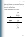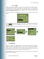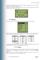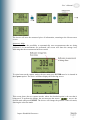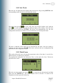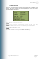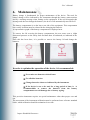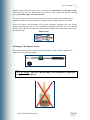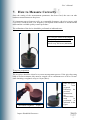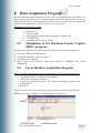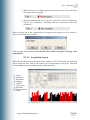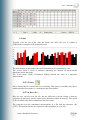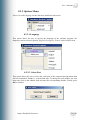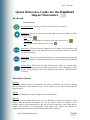
1
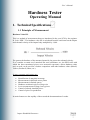
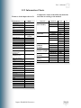
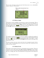
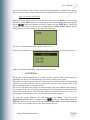
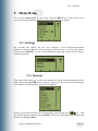
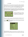
User´s Manual I M PACT HAN DHELD DUROM ETER User’s Manual INDEX 1. Technical Specifications……………………………………………………………….. 1.1 Principle of Measurement………………………………………………………….. 1.2 Technical Features .................................................................................................... 1.2.1 Technical Features of the Impact Device D ...................................................... 1.2.2 Information Charts……………………………………………………………. 1.2.3 Technical Features of the Electronic Unit ......................................................... 2 Keyboard Description ...................................................................................................... 4 4 5 5 6 7 8 3 Start up Screen ................................................................................................................. 9 4 Menu Descriptions ........................................................................................................... 10 4.1 Change Option………………………………………………………………………. 10 4.2 Statistics Option (Stat)……..…………………………………………………….... 10 4.3 Memo Option (Mem).…………………………………………………………………… 11 4.3.1 Store………………………………………………………………………… 11 4.3.2 Place Label………………………………………………………………….. 12 4.3.3 Delete Last………………………………………………………………….. 12 4.3.4 Close………………………………………………………………………… 13 5 Main Menu ....................................................................................................................... 14 5.1 Settings ..................................................................................................................... 14 5.1.1 Material ........................................................................................................ 14 5.1.2 Units ............................................................................................................. 15 5.1.3 Angle ........................................................................................................... 17 5.2 Alarms ...................................................................................................................... 017 5.3 Memory……………………………………………………………………………. 19 5.3.1 Samples …………………………………………………………………… 19 5.3.2 Capture……………………………………………………………………. 20 5.3.3 Free: ####…………………………………………………………………. 22 5.3.4 View List………………………………………………………………….. 22 5.3.5 Histogram..………………………………………………………………… 23 5.3.6 Delete……………………………………………………………………… 24 5.3.7 Send……………………………………………………………………….. 25 5.4 Language…………………………………………………………………………… 25 5.5 Configuration………………………………………………………………………. 26 5.5.1 Auto Off…………………………………………………………………… 26 5.5.2 Set clock…………………………………………………………………… 27 5.5.3 Date Form…………………………………………………………………. 28 5.6 Information…………………………………………………………………………. 28 6. Maintenance…………………………………………………………………………… 29 7. How to Measure Correctly……………………………………………………………. 31 8. Data Acquisition Program…………………………………………………………….. 34 8.1 Installation of the Acquisition Program……………………………………………. 34 8.2 Use of the Acquisition Program……………………………………………………. 34 8.2.1 File Menu .......................................................................................................... 34 8.2.1.1 Read .......................................................................................................... 34 8.2.1.2 Acquisition Screen .................................................................................... 34 8.2.1.3 Save ........................................................................................................... 40 8.2.1.4 Save As ..................................................................................................... 40 8.2.1.5 Open .......................................................................................................... 40 8.2.1.6 Print ........................................................................................................... 40 Impact Handheld Durometer Page 2 User’s Manual 8.2.1.7 Report …………………………………………………………………….. 41 8.2.1.8 Export to Excel……………………………………………………………. 42 8.2.1.9 Exit….………………………………………………………………….…. 42 8.2.2 Options Menu…………………………………………………………………... . 42 8.2.2.1 Language……………………………………………………………....…. 42 8.2.2.2 Select Port………………………………………………………………… 43 Quick Reference Guide………………………………………………………………………. 44 Impact Handheld Durometer Page 3 User’s Manual Hardness Tester Operating Manual 1. Technical Specifications 1.1 Principle of Measurement Hardness Value HL This is a method of measurement that was introduced in the year 1978 by the engineer D. Leeb “HDL”. The hardness value HL is calculated from the ratio between the impact and rebound velocity of the impact body multiplied by 1,000. The greater the hardness of the measured material, the greater the rebound velocity. If we consider a certain set of materials like steel, aluminum, etc., the HLD value with which the above-mentioned pieces were measured represents a direct hardness value and, as such, can be used for a further comparison with other hardness values (Brinell, Vickers, Rockwell, Shore, etc.). Its most common applications are: • • • • • • • Identification of materials in storage Measurements in difficult access points Measurements in limited spaces Hardness variation in pieces of large size In situ measurements of large, heavy pieces Control of already installed pieces Control of pieces in production Its main features are the rapidity of the test and the documentation of results. Impact Handheld Durometer Page 4 User’s Manual 1.2 Technical Features 1.2.1 Technical Features of the Impact Device D Features of the impact device D Length: Diameter: Weight: Maximum test hardness: 147 mm 20 mm 75 g 940 HV Features of the impact body D Impact energy: Mass of the impact body: Test tip: Diameter: Hardness: Material: 11 N.mm 5.5 g spherical 3 mm 1600HV tungsten carbide Indentation of the test tip At 300 HV At 600 HV At 800 HV Diameter: Depth: Diameter: Depth: Diameter: Depth: Impact Handheld Durometer 0.54 24 0.45 17 0.35 10 mm μm mm μm mm μm Page 5 User’s Manual 1.2.2 Information Charts Features of the impact device D Impact device Technical Information Impact Energy Mass of the impact body Impact Tip Diameter Hardness Material Impact device Length Diameter Weight Maximum Hardness Surface preparation Roughness Class ISO Maximum Roughness Rt Maximum Roughness CLA Minimum sample weight Compact material On rigid support Coupled with paste Minimum sample thickness Coupled Min. sf. Thickness Penetration with impact tip With 300 HV Diameter Depth With 600 HV Diameter Depth With 800 HV Diameter Depth D/DC 11 N.mm 5.5 g 3 mm 1600 HV Tungsten carbide 147/86 mm 20 mm 75/50 g 940 HV N7 10 µm 2 µm 5 Kg. 2 Kg. 0.1 Kg. Comparative chart of the different materials and units according to the method Material Steel and Steel Foundry Tool Steel Stainless Steel Iron Foundry Laminar Graphite Iron Foundry Nodular Graphite Aluminum Foundry Copper-zinc Alloy (Brass) Bronze Copper Alloys Method Vickers Brinell Rockwell Shore Vickers Rockwell Vickers Brinell Rockwell Brinell Vickers Rockwell Brinell Vickers Rockwell Brinell Rockwell Brinell Rockwell Brinell Brinell Scale HV HB HRB HRC HRA HS HV HRC HV HB HRB HRC HB HV HRC HB HV HRC HB HRB HB HRB HB HB D 80-940 80-647 38-99 20-68 ---------32-99 80-898 20-67 85-802 85-655 46-101 20-62 93-334 ------------------131-387 ------------------30-159 -------40-173 13-95 60-290 45-315 3 mm 0.8 mm 0.54 mm 24 µm 0.45 mm 17 µm 0.35 mm 10 µm Impact Handheld Durometer Page 6 User’s Manual Preparation of the pieces to be tested Roughness: Minimum sample weight Minimum sample thickness: Minimum radius of curvature: ISO N7, 10 μm RT, 2 μm RA 5 kg (compact piece) <5 kg (supp. by a piece with a greater solid mass) 3 mm 0.8 mm (thickness of superficial treatment) 30 mm 1.2.3 Technical Features of the Electronic Unit Graph screen 128 x 64 with backlight Visible area Easy-to-use acquisition program Fully programmable through the keyboard Connection to impact units Hardness units 46 mm x 30 mm Precision Impact direction Test material +/- 0.5% (referred to l = 800) +/- 4 HL units Selectable in all directions Steel, Grey Foundry, Bronze, Copper, Nodular, Aluminum, Brass, Steel for Tools and Stainless Steel Graphical and digital display of hardness Statistical data Hardness limits Data memory Data output Power supply Size Weight Impact Handheld Durometer D HB (Brinell) HV (Vickers) HRC (Rockwell C) HRB (Rockwell B) HS (Shore D) HL (Leeb) Maximum value (max) Minimum value (min) Range (r) Mean (x) Number of measurements Histogram of measurements Programmable with visual display 1974 pieces of information RS232 2 AA batteries Length: approx. 120 mm Width: approx. 65 mm Thickness: approx. 22 mm 154 g Page 7 User’s Manual 2. Keyboard Description The function of each keyboard key is described next. Switch-On Key: This key is used to turn the device on and off. Light key This key is used to turn on the light of the screen. There are three lighting states. Off: no light. Automatic: the light turns on whenever the user presses a key or performs a measurement. On: The light is always on. This key can be used at any moment, as it is a shortcut key. Every time this key is activated, the lighting state changes showing the following screens according to the selected state: Once the selection has been made, the different menu screens will display the icon corresponding to the lighting state chosen. Menu Key: This key has two functions: one of them is to access the main menu of the device (in the Measurement screen) and the other is to exit from the different menus. Enter Key: This key also has two functions: in the measurement screen, the key is used to store collected data and also to access options from different menus. Screen Keys: The device has three of these keys, which are located under the screen. These keys run the different options or menus that appear on the screen. The functions of these keys depend on the menu in which the user is working. Impact Handheld Durometer Page 8 User’s Manual 3. Start up Screen After turning the device on, the first screen that appears is: Measurement value Shows the measured value expressed in the selected unit. Selected unit Shows the selected measurement unit. Impact device direction Shows the direction of the impact device at the moment of the measurement. Battery status monitor This is a battery-shaped icon that shows the status of the battery charge. As the battery discharges, this icon changes its appearance as shown next. Measurement value expressed in Leeb The device always shows the measurement value in Leeb, regardless of the unit selected by the user. Selected material Indicates the material that has been selected to perform the measurement. Impact Handheld Durometer Page 9 User’s Manual 4. Menus Description 4.1 Change Option By pressing here the device offers the possibility to change, in the measurement screen, the unit, the material to measure and the direction of the impact device. To activate this option, the user must press the screen key on the right (located under the Change option). That way, the arrow showing the direction of the device will start blinking to indicate the change can already be made. The user must utilize the arrows to make the desired changes. Upon pressing them, the blinking icon will change showing the different existing options. Once the desired option has been found, the user must press the ENTER key to return to the Measurement Screen with the change already made. If the user wishes to make any other change before returning to the Measurement Screen, he must press Change again. In consequence, the device will save the change and continue on to the following option. To return to the Measurement Screen without making any change, the user must press the MENU key or press the Change screen key until the options stop blinking. 4.2 Statistics (Stat) This option offers statistical data about the group of measurements the user is working with. With just pressing the Statistics screen key in the measurement screen, the device will show the following graph with the corresponding statistical data. The height of the graph bars stand for the value of the measurements while the amount of bars are equal to the number of stored measurements. Impact Handheld Durometer Page 10 User’s Manual Min: Minimum value in the group of measurements. Mean: Average value of the measurements. Range: Measurement range. Max: Maximum value in the group of measurements. G: Measurements group (See 5.3 Memory). N: Amount of samples in the group of measurements. If no data were stored in the device Memory when this option is activated, the following screen will appear. 4.3 Memo Option (Mem) This menu provides options referred to the data storage of the device. To access this menu, the user must be located in the Measurement screen, then press the Memo screen key. The device will display the following screen: 4.3.1 Store This option is used to manually store the measured data. The user must only press the ENTER key on the Store option and the device will store the last value obtained. The upper part of the screen will show this icon indicating that the storage was successful. There is also another way to manually store measurements. When the user is performing measurements and wishes to store one of them, by pressing ENTER in the Measurement Screen, the device will store the measurement appearing on the screen. Impact Handheld Durometer Page 11 User’s Manual The icon Store will appear in the upper part of the Measurement screen, confirming the storage of that piece of information. 4.3.2 Place Label This function is used to highlight a measurement or a group of measurements. Thus, at the moment of viewing all measurements, the labelled ones will be easily identified. To place a label, the user must press the Memo screen key in the Measurement screen and after that, with the arrows he will have to search the Label option and then press ENTER. The device will then show the following screen: The underscore under the last number (in this case number 1) indicates the position of the user. By using the arrows , the user will select the desired number and with the arrow he will navigate through the different digits of the number. To make the change effective, the user must press ENTER. Then, the device will return to the Measurement screen. The labels placed by the user can be read in the device through the option ViewList (refer to page 22) and through the data acquisition program once the data have been transferred to the computer. 4.3.3 Delete Last This option is used to delete the last piece of information stored in memory. The device will remove the last value directly and with no previous confirmation. This will allow to delete, one by one, all stored values until the elimination of the whole group of values the user is working with. Once all measurements in the group have been deleted, the Impact Handheld Durometer Page 12 User’s Manual user will no longer be able to delete measurements belonging to already closed groups. The only way to remove these measurements is through the option Delete (see page 24). How can a value be deleted? Positioned in the Measurement Screen, the user must press the Memo screen key.Once the user is in the Memo option, he must look for the function Delete Last by using the arrows . When this function is found, he must press the ENTER key. The device will then remove the last stored piece of information without further notice, and the following screen will be shown at the end of the operation. The device will then return to the Measurement screen. If no piece of information can be deleted, the device will display the following screen: And it will automatically return to the Measurement screen. 4.3.4 Close The groups of measurements have a limited storage capacity. When their capacity is exhausted, the device will automatically close them, opening a new group. This option is aimed to provide the user with a way to close the groups of measurements whenever necessary with no need to exhaust the capacity of the groups. This is the reason why this option is extremely useful. The device will also close groups of measurements if the user modifies their capacity. For example, if the user is working with groups of five measurements and changes their capacity to ten, the device will close the current five-measurement group, even if it is not complete, and will open a new one with the new storage capacity. To make this option effective, the user must press the Memo screen key in the Measurement Screen, and by using the arrows search the option Close and press ENTER. The device will close the group without further notice and will automatically create a new one to finally return to the Measurement Screen. Impact Handheld Durometer Page 13 User’s Manual 5. Main Menu To access the Main menu, the user must press the MENU key in the Measurement screen. He will then find the following menu with its different options: 5.1 Settings By selecting this option, the user will configure several measurement-related parameters, such as: Material, Unit and Angle of Measurement. To access this option, he must press ENTER on it. He will then find the following screen with the abovementioned options. 5.1.1 Material This option allows the user to select the material on which the measurements will be made. By pressing ENTER on the respective option, the user will access the following screen where he will be able to select the test material. In order to select the material, the user must only scroll with the arrows to find the desired material and then press ENTER. The device will change the material and return to the Settings Menu. Impact Handheld Durometer Page 14 User’s Manual 5.1.2 Units This option allows the user to choose the unit in which he wishes to display the measurement results. It is necessary to bear in mind that measurement units depend on the material to be measured. For example, if the material to be measured is Bronze, the units in which results can be expressed are Leeb and Brinell, but if the material to measure is Brass, the corresponding units can be Leeb, Brinell and Rockwell B. Something important to take into account is that the Leeb unit is always taken as a reference. This means that if a measurement expressed in Leeb (HLD) produces a result of 500 HLD, there will be no corresponding value in Rockwell C, since its range starts from 510 HLD (510 HLD = 20.00 HRC). If values in different units cannot correspond to each other, the device will display the following screen: For this reason, when the user needs to express measurements in another unit, he must be attentive to the range of application of such measurements (refer to chart in page 6). To access press ENTER on the option. Then, to select the units, choose the unit with the arrows and press ENTER on the option. The device adopts the selected unit and returns to the Settings Menu. Mechanical Resistance (N/mm2) is not a unit but the value of traction resistance of a certain material. The device converts hardness values to mechanical resistance values through the conversion table DIN 50150. The conversion procedure consists in taking Impact Handheld Durometer Page 15 User’s Manual an experimentally obtained hardness value to find the corresponding traction resistance value according to the table. The values from the table should be considered approximate values that will not at all replace those obtained through the traction test. This is due to differences in the development of deformation between hardness measurements and traction tests. These differences generate, among other aspects, a different state of tension and a different deformation velocity. Another source of error is the wide variation between the deformation-tension behaviour of different steels. A table with the units corresponding to each material is shown next: MATERIAL Steel Cast Bronze Copper Nodular Aluminium Brass Tool Steel Stainless Impact Handheld Durometer UNITS Leeb Brinell Vickers Shore Rockwell C Rockwell B RM (N/mm2) Leeb Brinell Leeb Brinell Leeb Brinell Leeb Brinell Leeb Brinell Leeb Brinell Vickers Leeb Vickers Rockwell C Leeb Brinell Vickers Rockwell C Rockwell B Page 16 User’s Manual 5.1.3 Angle When performing measurements, the choice of the impact device inclination angle is very important since it influences the outcome of the measurement. If, for instance, the user has selected a 90º angle and performs a measurement at 180º, the result will not be accurate. This is why it is so important to adequately select the angle before performing the corresponding measurement. To access this option, press ENTER on Angle; the device will show the Angle selection screen. To make the selection effective, the user must choose the measurement angle with the arrows and then press ENTER on the desired angle. The device will return to the Settings Menu. The measurement screen will then display the icon corresponding to the selected angle. 5.2 Alarms Alarms are values to be configured by the user. These values determine the maximum or minimum tolerance limits. When the results of a measurement are below the minimum limit or above the maximum limit, the Alarm will be activated. The Alarm is represented in the Measurement screen by a bell-shaped icon that shows the user that the measurement values are not within the default tolerance limits. It is important to bear in mind that whenever the measurement unit is changed, the alarms must be reestablished. Impact Handheld Durometer Page 17 User’s Manual This option allows to edit alarm values. By pressing ENTER on the Alarm option in the Main Menu, the user accesses the Alarm screen. In this screen, the current High and Low Alarm values are displayed. By using the arrows the user can select the Alarm he wishes to edit and afterwards, by pressing the ENTER key, he will access the Alarm editing screen. The underscore under the last number (in this case number 0) indicates the position of the user. By using the arrows the user selects the desired number and with the arrow navigates through the different digits of the number. To make the change effective, the user must press ENTER. Afterwards, the device will return to the Alarm option, where the change will be displayed. Once the Alarms have been selected, when the user performs a measurement and the obtained value is outside of the selected tolerance limits, the device will display in the Measurement screen the icon appearing next. To deactivate both Minimum and Maximum Alarms, the user must access the Alarm editing screen to set up a value of 0 for the minimum alarm and a value of 1000 for the maximum alarm. This way, the user will select the maximum and minimum Impact Handheld Durometer Page 18 User’s Manual measurement peaks of the device and, as a result, the alarms will never come into operation, becoming thus deactivated. The Alarm icon will also appear on the screen if any of the measurements does not fall within the range of the selected unit 5.3 Memory In this menu, the user will find different options related to the device Memory. In the Memory the stored samples are distributed in groups, its capacity depends on the number of samples that the user has selected (See 5.3.1 Samples, Page 19, Group Capacity). It is important to know that the unit of the data stored in the Memory is always Leeb, regardless the unit in which measurements have been made. 5.3.1 Samples This option allows the user to select the amount of data he wishes to store per group of measurements. The maximum sample number per group is 16 and the minimum number is 1. When the user stores data and completes the group, the device closes it and automatically opens a new one without further notice. Impact Handheld Durometer Page 19 User’s Manual The number of samples can be changed at any moment, but it is important to know that, when a sample number is changed, the devices closes the current group and opens a new one with the newly selected capacity. To perform this change, the user must select this option and press ENTER. He will make the change effective in the following screen. To change the number of samples, the user must select the desired number with the arrows and change the digit with the arrow . Once the number of measurements has been chosen, the user must press ENTER. If the user wishes to exit without performing any change, he must press the MENU key. 5.3.2 Data Capture Through this option, the user can select the data storage mode of the device. The device has two capture modes: Manual and Automatic. Manual Mode This option allows the user to store only the piece of information he wishes or deems necessary. The manual data storage can be performed in two different ways. One of them (the fastest way) is by pressing ENTER in the Measurement screen, after the measurement has been carried out. The device will show the storage icon and will be ready for a new measurement, as shown below. The other way to save data is performing the following steps: • • • Press the Memo screen key Select the Store option Press ENTER Impact Handheld Durometer Page 20 User’s Manual The device will save the measured piece of information, returning to the Measurement screen. Automatic Mode This mode offers the possibility to automatically store measurements that are being performed. As measurements are performed, the screen will show the storage icon, indicating that the measurement has been stored. To select between the capture modes, the user must press ENTER once he is situated in the Capture option. The device will then display the following screen: This screen shows the two capture modes, where the checked option is the one that is being used. To perform the change, the user must use the arrows to access the desired mode and press ENTER. The device will change the position of the tick mark, showing the selection made. Impact Handheld Durometer Page 21 User’s Manual After the selection has been made, the user must press MENU to exit. 5.3.3 Free: #### The “Free: ####” option is informative in nature and indicates the free storage capacity of the Memory. To access it, the user must be located in the “Free: ####” option and press ENTER. Next, he will access a screen indicating the free memory spaces. Since this option is informative in nature, there is no need to access it to know the value it contains. For example, if the option says: Free: 1508, this means that the available memory capacity is of 1508 spaces. The maximum Memory capacity is 1974 spaces. 5.3.4 View List This option shows the data that are stored in the Memory, in the same order in which they were stored and in their corresponding groups. Besides showing the stored data, it also shows the labels, if they exist. When accessing this option, the values of the stored measurements appear on the screen as shown next: Impact Handheld Durometer Page 22 User’s Manual Sample Group: indicates the data group in which the user is located. Measurements: these are the measurements in the order in which they were stored. Down arrow: this key is used to scroll the set of measurements in which the user is located. Begin: returns to the first value of the group. Next: jumps directly to the following group. ENTER Key: returns to the first data group. If there are empty data groups (with no stored data) in the list, these will appear in the following way: 5.3.5 Histogram Here the user will find a bar graph and several statistical data about each measurement group. The difference with the Statistics option (in the Measurement screen) is that the Histogram provides graphs and statistics for all existing measurement groups while the first option only displays the graphs and statistics of the current working group. To access this tool, the user must select the Histogram option and press ENTER. The device will show a screen with the data and the graph for the first group of measurements. By using the screen keys, the user may scroll through the groups of measurements, watching the graphs and statistics for each of them. Impact Handheld Durometer Page 23 User’s Manual If no data were stored in the device Memory when this option is activated, the following screen will appear: This screen will also appear if an empty group is found when scrolling through the group of measurements. 5.3.6 Delete Here the user can delete all existing data In the Memory. By using this option the user will not be able to select the group or the values to delete, but will clear all stored data. To access this option, the user must press ENTER on it. The device will then display a screen asking the user if he would like to delete data. By pressing the YES Screen Key, the device will start deleting all data stored in the Memory. While data are being removed, the device will show a screen indicating the progress of the task and then another screen saying that the process has been completed. Once the process is done, the device will return to the Memory Menu. If the user chooses the “NO” option, the device will return to the previous screen. WARNING: Once data have been deleted, they cannot be recovered Impact Handheld Durometer Page 24 User’s Manual 5.3.7 Send This option allows transmitting the data stored in the device’s Memory to the computer. To carry out the transmission, the user must have the capture program installed in the computer and connect the device to it through the RS232 cable (provided with the device). To start transmission, the user must press ENTER on the corresponding option. The device will show the following screens: 5.4 Language By selecting this option, the user can specify the language of the software program. Six languages can be selected: Spanish, English, Portuguese, French, Italian and German. To make effective any of these changes, the user must access the Language option and press ENTER. The following screen will appear: Now, by using the arrows the user can access the desired language and then confirm the change by pressing ENTER. The device will then return to the Options Menu in the selected language. Impact Handheld Durometer Page 25 User’s Manual 5.5 Configuration By pressing ENTER on the Configuration option, the following menus will appear: 5.5.1 Auto Off This function helps the user to care for the batteries used in the device. If the user performs a measurement and forgets to turn the device off, the instrument will turn itself off after several minutes of inactivity (determined by the user). The user can select how long he would like the device to remain active without receiving any input. This period of time could be between 4 minutes (minimum) and 30 minutes (maximum). To access this function, the user must select Auto switch off and press ENTER. The following screen will appear: To make the change, the user must employ the arrows to search for the desired number and the arrow to scroll through the digits. Once the number has been selected, he must press the ENTER key to confirm the change. The device will save the change and will automatically return to the Configuration Menu. Impact Handheld Durometer Page 26 User’s Manual 5.5.2 Set Clock Here the user can adjust the hour and the date of the device. By pressing ENTER on the corresponding option, the device will show this screen: By means of the arrows the user will select the desired number and with the arrow he will navigate through the different digits of the number. Once the hour has been set, he must press ENTER. The device will automatically save the new configuration and move to another screen in which the user will adjust the date. The date is adjusted in the same way as described for the hour. Once the setting is complete, the user must press ENTER. The device will save the new configuration and will return to the Configuration menu. 5.5.3 Date Form This option allows the user selecting the appearance order of the date. It can be Day, Month and Year or Month, Day and Year. To complete the setting the user must press Enter on the option Set. Date. The device will show this screen: Here the user must employ the arrows to search for the desired mode and then must press the ENTER key. The desired option will be selected. To return to the Configuration Menu press the Menu key. Impact Handheld Durometer Page 27 User’s Manual 5.6 Information This screen shows miscellaneous information concerning the status of the device, such as Hour, Date, Serial and Impact. The screen displayed by the device when the user accesses this option is shown next. Serial: Shows the serial number of the device. Impact: Shows the amount of measurements performed with the device. This information will be saved in the device even if the memory is completely deleted. Version: Indicates the software version. To exit this screen, the user must press the MENU or ENTER keys. Impact Handheld Durometer Page 28 User’s Manual 6. Maintenance Battery change is fundamental for proper maintenance of the device. The need for battery change will be indicated by the instrument through the battery status monitor and by a warning message when turning on the equipment. If the user disregards this message and does not change the batteries, the device will automatically turn itself off. The battery compartment is on the lower rear side of the equipment. This compartment has a safety lock that must be released before changing the batteries. A representative graph of the battery compartment is displayed next. To remove the lid covering the battery compartment, the user must exert a slight downward pressure on the safety lock and then draw it backwards, as indicated in the graph. Once this has been done, it is possible to remove the battery lid and change the batteries. In order to optimize the operation of the device, it is recommended: Not to mix new batteries with old ones. Use alkaline batteries. Change batteries whenever indicated by the instrument. If the device is not to be used for a long period of time, it is recommendable to remove the batteries from the battery compartment to avoid damage due to battery ageing. This precision instrument requires no special maintenance other than proper care and use. The assessment of the instrument calibration must be performed on a reference standard block, which calibration should be maintained over time. Impact Handheld Durometer Page 29 User’s Manual Another important point to take into account is the maintenance of the impact body. This body does not need lubrication of any kind; it only requires an internal cleaning using, if possible, light, non-fatty solvents. The impact body is the element to control in the course of time. This element has a tungsten carbide tip with a useful life of approximately 10.000 impacts of 600 HL. If this tip flattens, the durometer will provide erroneous readings, since the energy absorbed during the impact will be unsuitably distributed between the piece and the impact body. This defect cannot be corrected and requires the replacement of the tip of the impact body. Impact body Cleaning of the impact device The impact device must be cleaned with the brush provided with the equipment as indicated in the following image: 1 CAUTION: The user should under no circumstance lubricate any part of the device Impact Handheld Durometer Page 30 User’s Manual 7. How to Measure Correctly Once the setting of the measurement parameters has been fixed, the user can take hardness measurements on the pieces. It is important not to forget to verify, at a reasonable frequency, the device impact with a reference standard block. The frequency will depend on the number of measurements taken and the available quality control procedure. The calibration of the device should be performed as indicated next: To verify the status of the impact device, it is recommendable to take 3 to 5 points on a standard block every 500 tests (minimum). Test piece preparation The test piece should be clean for a correct measurement process. If the piece has some kind of surface treatment, this must be scraped off in a minimum area of 20 to 30 mm2 until obtaining a roughness of up to 10 μm (Rtmax). Maximum roughness 10 μm Impact Handheld Durometer Once the piece has been prepared following the previous instructions, the measurement must be performed as indicated in the figure. Page 31 User’s Manual Take the impact device and load the impact body compressing it against the piece to be measured as illustrated below. Hold the device with both hands, avoiding to move it at the moment of the reading. Press the button on the upper end of the impact device. At this moment, a test will have been made. Simultaneously, the device screen will display the value of hardness obtained in the selected scale. As in any other control procedure, take at least 3 samples at a distance not exceeding 4 mm from each other. These measurements should not have a difference of more than +/6 HDL units. If the difference were greater, verify the support of the impact device and the correct support of the piece. If the lack of reproducibility is accompanied of values below the real value, this indicates that the mass of the piece is too small or that a part of the impact energy is being absorbed by the support of the piece. Impact Handheld Durometer Page 32 User’s Manual Since this is a dynamic test, it is important that the piece is perfectly supported. Pieces with a mass smaller than 5 kg can be measured on a higher mass support perfectly coupled by the couple paste provide with the device. Fat or lubricant layers have to be avoided, since they behave like shock absorbers at the moment of the impact. This technique requires a certain experience and a very fine finishing of the surfaces to be coupled. Impact Handheld Durometer Page 33 User’s Manual 8. Data Acquisition Program The data acquisition program has been conceived as a complementary tool for the user. This program allows the user to download to his computer the data stored in the device, analyze statistically the measurements performed, store protocols and test reports, and save this information to his computer and recover it at any time. Minimum system requirements 8.1 Pentium II RAM: 128 Mb Operating System: Microsoft Windows 98, 2000 or XP CD-ROM drive Required hard disk space: 10 Mb Installation of the Hardness Pocket Capture (HPC) program The following steps must be observed in order to install the acquisition program: • • • • Insert the CD in the CD-ROM drive Launch the Windows “Start-up” menu Open the “Run” submenu Next, click on the “Browse” button and locate the CD-ROM drive. Select “Setup.exe”. 8.2 Use of the Data Acquisition Program To run the Data Acquisition Program, the user must perform the following steps: 1. Launch the “Start-up” Menu from the taskbar 2. Choose the “Programs” submenu 3. Choose the program group where HPC has been installed (“Capture” is the default folder) 4. Run HPC The user can also access the program using the shortcut installed on the desktop. When the program is running, the following screen will appear: Impact Handheld Durometer Page 34 User’s Manual Shortcuts: By means of the following icons, the user will access directly to some of the options and tools of HPC. 8.2.1 File Menu This menu has eight submenus: Read, Save, Save as…, Open, Print, Report, Export to Excel and Exit. 8.2.1.1 Read: This submenu allows the operator to transmit data from the device to the computer. To do it properly, the user must perform the following steps: 1. Connect the device to the serial port (COM) of the computer using the cable provided with the instrument 2. Run DP-Capture software 3. Click on the “Receive” option The lower part of the screen will show the legend “Waiting transmission…” that indicates that the program is ready to receive the transmission of the data stored in the device. 4. Now the device will start sending the stored data (refer to point 5.3.7 – Data transmission from the device to the computer). Impact Handheld Durometer Page 35 User’s Manual 5. While the device is sending data, the lower part of the screen will show the legend “Receiving data…” 6. When the transmission is over, the lower part of the screen will show the legend “No connection”, indicating that the transmission has been completed. Before carrying out a new transmission, the program will ask the user if he wishes to save the previously received data. If the operator chooses not to save the data, these will be lost upon receiving a new transmission. 8.2.1.2 Acquisition Screen When the data have been transferred to the computer, HPC will display the following screen where the user will see the whole set of measurements carried out, with their corresponding assessment charts, among which stand out: a) Select b) Statistics c) Resistance d) Settings e) Alarms f) Conversion g) Remarks h) Measurements i) Graph Impact Handheld Durometer Page 36 User’s Manual Description of the assessment charts a) Select This dialog box allows the user to select the set of data he wishes to work with. If he selects All, he will work with the whole set of measurements as a unique set of values. If he selects Batch, he will work with the values belonging to one particular set. Once the option Batch has been chosen, the user must select the group he desires to work with. For that purpose, he must click on the tab of the chart corresponding to the desired set of values. If the user selects ID (label), the program will take all those values comprised between two labels. This may cover from one single value to several sets of values. b) Statistics This chart shows different statistical data based on the obtained values, whether they are from one particular batch or from the whole set of measurements. This will depend on the user's selection. Maximum: maximum measured value. Minimum: minimum measured value. Range: difference between maximum and minimum values. Average: average sample value. Standard Deviation: average distance between individual thickness values and their mean. Samples: total number of values or values stored in the batch, as selected by the user. Porcentage Ok: amount of values that are within the tolerance limits. c) Resistance This dialog box illustrates the mechanical resistance of a particular hardness value (selected by the user). Impact Handheld Durometer Page 37 User’s Manual d) Settings This dialog box shows particular features of the selected measurement. Material: shows the material on which the measurement was performed Unit: shows the unit in which the measurement is expressed Impact: Together with the arrow, shows the sense of the device at the moment of the measurement. Omit This option offers the user the possibility of omitting one or several values in the grid. In order to omit a value, the user must click on the value to be omitted and enter Omit Value. Once the value has been omitted, statistics, graphs and other information involving the omitted value will be recalculated and therefore produce new results. In order to restore the omitted value, the user must click on it. Afterwards, a dialogue box will pop-up, providing the user the possibility of restoring the value or leaving it in as it was. By clicking on Yes, the value goes back to the grid and by clicking on No, the value will continue to be omitted. e) Alarms Here the operator can select the Maximum and Minimum tolerance limits. Alarm editing will facilitate the identification of measurements falling out of the tolerance range or near the limit of acceptability. The alarms will be represented both in the graph of measurements and in the table. To deactivate the Alarms, the user must set the Minimum Alarm to 0 and the Maximum Alarm to 1000 (whole working range of the device). That way, alarms will never come into operation. Impact Handheld Durometer Page 38 User’s Manual f) Conversion Through this option, the operator can select the unit in which he wants the measurements to be expressed, since the device only saves data in Leeb units. While measurements are being converted to another unit, a status bar will indicate the progress of the conversion process. Upon the completion of the conversion process, certain values may fall out of the range for that unit; hence empty cells will appear in the table of values. g) Remarks Through this option, the user may write any comments deemed necessary regarding any values in the grid. Once the comments are written, the user must click Enter to finally add them. Now, in the grid, the commented value will appear in Bold and by placing the mouse on it, the comment made will appear. The maximum number of characters for each comment is 50 To remove the comment, the user must place the mouse on the commented value and press Delete. h) Measurements This chart illustrates the measurements in the order in which they were taken, as well as the labels and the values that fall out of the tolerance limits. Impact Handheld Durometer Page 39 User’s Manual i) Graph Together with the rest of the data, the graph will allow the user to conduct a comprehensive analysis of the measured pieces. The main feature of this graph is that each measurement is represented by a bar. The X-axis shows a series of numbers indicating the amount of measurements distributed across the graph. The Y-axis shows values of hardness helping identify the value of a particular measurement. 8.2.1.3 Save Saves directly the file in which the user is working. This option is available only after a transmission has been made or a working file has been loaded. 8.2.1.4 Save As… Here the user can also save the file, but the difference with the former is that the program will ask him to specify a name and a destination folder for that file. This option is also available only after a transmission has been made. The program saves the transmitted measurements in a file with the extension .dpc (HPC). This format can later be exported to other programs as a text file. Impact Handheld Durometer Page 40 User’s Manual 8.2.1.5 Open This option allows the user to load previous reports in order to continue their analysis. HPC’s extension is .dpc. Once the desired file has been located, the user must click on the Open button. 8.2.1.6 Print This option is used to print the report in which the user is working. When this option is activated, the following dialog box appears: This dialog box will allow the operator to select the printer with which the report will be printed. By pressing Accept, report printing will begin. By pressing Cancel, the program will close the dialog box returning to the acquisition screen. Also this dialog box will allow the operator to print the graph or not ,or modified the report. An example of a printed report is shown next: Impact Handheld Durometer Page 41 User’s Manual 8.2.1.7 Report Here the operator will enter a screen that will allow him to prepare the report concerning the transmitted data. The user can enter data relating to the company and the test piece as well as a personalized report of the measurements. Company Data: This option allows the user to enter the name of the company and of the person who made the report. Piece Data: This option allows to enter data about the piece analyzed in the report. The user can make a personalized description of the piece. Report: This option allows the user to write down what he deems necessary to add about the measurements performed. 8.2.1.8 Export to Excel This option allows the operator to export the HPC format to an Excel format (.csv extension). That way, the data in the HPC table will be viewable in an Excel spreadsheet. Once the new file has been created, the user must run Microsoft Excel and then open the file. The name and the destination folder of the new file will be the same as the ones the file had before being exported. 8.2.1.9 Exit Exits the HPC program without further notice. Impact Handheld Durometer Page 42 User’s Manual 8.2.2 Options Menu Select Port and Language are the functions included in this menu. 8.2.2.1 Language This option allows the user to specify the language of the software program. Six languages can be selected: Spanish, English, Portuguese, French, Italian and German. 8.2.2.2 Select Port This option allows the user to select the serial port of the computer through which data will be transmitted. Number 1 is the default port. To change the port number, the user must only click on the editable field and enter the corresponding number. Finally, press OK to confirm. Impact Handheld Durometer Page 43 User’s Manual Quick Reference Guide for the Handheld Impact Durometer Keyboard Function keys: Switch-On Key: This key is used to turn the device on and off Light key This key is used to turn on the light of the screen. There are three lighting states: Off: no light. Automatic: the light turns on whenever the user presses a key. On: the light is on while the device is on. Menu Key: This key has two functions: one of them is to access the main menu of the device (in the Measurement screen) and the other is to exit from the different menus Enter Key: This key also has two functions: in the measurement screen, the key is used to store collected data and also to access options from different menus. Screen Keys: The device has three of these keys, which are located under the screen. These keys run the different options or menus that appear on the screen. The functions of these keys depend on the menu in which the user is working. Main Menu Options Settings Allows to select the Material to measure, the Unit in which the user wishes to display the measurement results and the Angle of the impact device when performing the measurement. Alarms Allows to establish the tolerance range of the measurements. Memory Here the user can control and/or select several functions referred to the memory of the device, like the amount of samples per set, the capture mode, the number of free memory spaces, the measurements saved per set in the order they were saved and the graphs and statistics of measurements. This option also allows the operator to completely delete the memory and send the data to the computer. Impact Handheld Durometer Page 44 User’s Manual Language Selects the language of the device. Configuration The user can select the auto-switch-off time, adjust time and date and choose the recognition mode of the angle of the impact device (Manual or Automatic). Information Shows a screen with the hour, date, serial number and the amount of measurements performed with the device. Options and Menus of the Measurement Screen Memo By accessing this menu, the user is able to perform several actions like Saving a measurement, Creating a label for a set of measurements o for a particular measurement, Deleting data of the last working group or Closing the group he is working with. Statistics This option shows a bar graph and several statistical data about the last set of measurements. Change This option allows the user to make changes in the measurement screen, with no need to access menus. The device allows the user to make the following changes: modify the angle of the impact device, select the material on which measurements will be performed and select the unit in which he wants to express the results of the measurements. V. 1.1 Impact Handheld Durometer Page 45