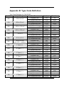
1
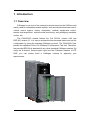
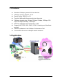
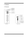
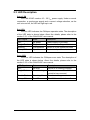
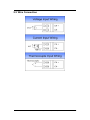
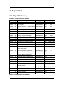
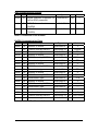
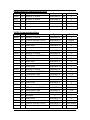
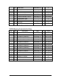
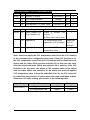
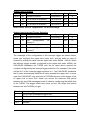
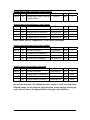
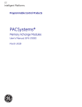
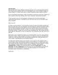
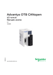
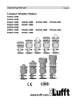
CANopen Slave Device
CAN-2018C
Application User’s Manual
Warranty
Without contrived damage, all products manufactured by ICP DAS are
warranted in one year from the date of delivery to customers.
Warning
ICP DAS revises the manual at any time without notice. However, no
responsibility is taken by ICP DAS unless infringement act imperils to patents
of the third parties.
Copyright
Copyright © 2009 is reserved by ICP DAS.
Trademark
The brand name ICP DAS as a trademark is registered, and can be used
by other authorized companies.
CAN-2018C user’s manual (Revision 1.0, Oct/2011) ------
1
Contents
1
2
3
Introduction.............................................................................................3
1.1 Overview.........................................................................................3
1.2 Hardware Specifications ...............................................................4
1.3 Features..........................................................................................5
1.4 Application .....................................................................................5
Hardware .................................................................................................6
2.1 Structure.........................................................................................6
2.2 Node ID & Baud Rate Rotary Switch ............................................7
2.3 LED Description .............................................................................8
2.4 PIN Assignment .............................................................................9
2.5 Wire Connection ..........................................................................10
Application ............................................................................................ 11
3.1 Object Dictionary ......................................................................... 11
3.2 Store and Restore Object ............................................................19
3.3 Application Object .......................................................................20
3.4 Default PDO Mapping ..................................................................21
3.5 EMCY Communication ................................................................22
Appendix A: Dimension...............................................................................23
Appendix B: Type Code Definition .............................................................25
CAN-2018C user’s manual (Revision 1.0, Oct/2011) ------
2
1 Introduction
1.1 Overview
CANopen is one kind of the network protocols based on the CAN bus and
mainly used for embedded network system, such as industrial machine control ,
vehicle control system, factory automation, medical equipments control,
remote data acquisition, environmental monitoring, and packaging machines
control, etc.
The CAN-2018C module follows the CiA DS-301 version 4.02 and
DSP-401 version 2.1. It is easy to access the thermocouple status and set the
configuration by using the standard CANopen protocol. The CAN-2018C has
passed the validation of the CiA CANopen Conformance Test tool. Therefore,
the provided EDS file is standard for any other standard CANopen masters. By
using the 8-channel thermocouple input and the CANopen masters of ICP
DAS, you can quickly build a CANopen network to approach your
requirements.
CAN-2018C user’s manual (Revision 1.0, Oct/2011) ------
3
1.2 Hardware Specifications
Analog Input:
z Input Channels: 8
z Input Type: +/- 15mV, +/- 50mV, +/- 100mV, +/- 500mV, +/- 1V, +/2.5V, -20mA ~ +20mA (Requires Optional External 125Ω Resistor),
z
z
z
z
z
z
Thermocouple(J, K, T, E. R. S, B, N, C)
Resolution: 16-bit
Accuracy: +/-0.1% FSR
Sampling Rate: 10 Samples/ sec (Total)
Zero Drift: +/- 10μV/ °C
Span Drift: +/- 25 ppm/ °C
Common Mode Rejection: 86 dB
z
z
z
z
z
z
z
Normal Mode Rejection: 100 dB
Input Impedance: >400 kΩ
Individual Channel Configuration: Yes
Open Thermocouple Detection: Yes
Over-voltage Protection: 240 Vrms
4 kV ESD Protection: Yes, Contact for each terminal.
Intra-module Isolation, Field to Logic: 3000 VDC
Others:
z Power LED: PWR (red)
z CANopen Status LED: RUN (green) / ERR (orange)
z Power Supply: Unregulated +10 ~ +30 VDC.
z Power Consumption: 1.5 W.
z Storage Temperature: -30 ~ +80 ℃.
z
z
Humidity: 10 to 90% RH, Non-condensing.
Dimensions: 32.3 mm x 99 mm x 78 mm (W x L x H) Detail.
CAN-2018C user’s manual (Revision 1.0, Oct/2011) ------
4
1.3 Features
z
z
z
z
z
z
z
z
z
Standard CANopen general I/O slave devices.
CANopen Version: DS-301, v4.02.
Device Profile: DSP-401, v2.1
Provide 8 differential thermocouple input channels.
CANopen transfer rate: 10 kbps, 20 kbps, 50 kbps, 125 kbps, 250
kbps, 500 kbps, 800 kbps, 1000 kbps.
Maximum CANopen slave Node-ID up to 99.
Support NMT, PDO, SDO, EMCY, SYNC, Guarding, and Heartbeat
protocol.
Pass the validation of the CANopen Conformance Test
Provide EDS file for the CANopen master interfaces
1.4 Application
CAN-2018C user’s manual (Revision 1.0, Oct/2011) ------
5
2 Hardware
2.1 Structure
(Top View)
(Bottom View)
CAN-2018C user’s manual (Revision 1.0, Oct/2011) ------
6
2.2 Node ID & Baud Rate Rotary Switch
The rotary switches for node ID configure the node ID of the CAN-2018C
module. These two switches are for the tens digit and the units digit of node ID.
The node ID value of this demo picture is 32.
Node ID rotary switch
The rotary switch for baud rate handles the CAN baud rate of the
CAN-2018C module. The relationship between the rotary switch value and the
practical baud rate is presented in the following table.
Baud rate rotary switch
Rotary Switch Value
Baud rate (k BPS)
0
10
1
20
2
50
3
125
4
250
5
500
6
800
7
1000
Baud rate and rotary switch
CAN-2018C user’s manual (Revision 1.0, Oct/2011) ------
7
2.3 LED Description
Power LED
The CAN-2018C needs a 10 ~ 30 VDC power supply. Under a normal
connection, a good power supply and a correct voltage selection, as the
unit is turned on, the LED will light up in red.
Run LED
The Run LED indicates the CANopen operation state. The description
of the LED state is shown below. About the details, please refer to the
section 2.3.1 of the CAN-2000C user manual.
LED Signal
State
Description
OFF
No power
Power Supply is not ready
Single Flash
Stopped
The device is in Stopped state
Blinking
Pre-operation
Device is in pre-operational state
Always ON
Operation
Device is in operational state
Error LED
The Error LED indicates the CANopen error state. The description of
the LED state is shown below. About the details, please refer to the
section 2.3.2 of the CAN-2000C user manual.
LED Signal
State
Description
OFF
No error
Device is in working condition.
Single Flash
Error Warning
At least one error of the CAN
controller has occurred.
Double Flash
Guarding fail.
Guard event happened.
Always ON
Bus Off
The CAN controller is bus off.
CAN-2018C user’s manual (Revision 1.0, Oct/2011) ------
8
2.4 PIN Assignment
CAN-2018C + CN-1824 (transformation connector)
CAN-2018C 25-pin Female D-Sub Connector
CAN-2018C user’s manual (Revision 1.0, Oct/2011) ------
9
2.5 Wire Connection
CAN-2018C user’s manual (Revision 1.0, Oct/2011) ------
10
3 Application
3.1 Object Dictionary
General Communication Entries
Idx
Sidx
Description
Type
Attr
Default
1000h
0h device type
UNSIGNED 32
RO
00040191h
1001h
0h error register
UNSIGNED 8
RO
0h
1003h
0h largest subindex supported for UNSIGNED 8
RO
0h
UNSIGNED 32
RO
---
...
...
---
5h actual error (the oldest one)
UNSIGNED 32
RO
---
1005h
0h COB-ID of Sync message
UNSIGNED 32
RW
80h
1008h
0h manufacturer device name
VISIBLE_STRING
RO
CAN-2018C
1009h
0h manufacturer hardware version
VISIBLE_STRING
RO
03
100Ah
0h manufacturer software version
VISIBLE_STRING
RO 1.00-20110930
100Ch
0h guard time
UNSIGNED 16
RW
0h
100Dh
0h life time factor
UNSIGNED 8
RW
0h
1010h
0h largest subindex supported for UNSIGNED 8
RO
1h
“predefine error field”
1h actual error (the newest one)
... ...
“store parameters”
1010h
1h save all hardware parameter
UNSIGNED 32
RW
---
1011h
0h largest subindex supported for UNSIGNED 8
RO
1h
“restore default parameters”
1011h
1h restore all default parameters
UNSIGNED 32
RW
---
1014h
0h COB-ID of EMCY
UNSIGNED 32
RW
80h+x
1015h
0h Inhibit time of EMCY
UNSIGNED 16
RW
0h
1017h
0h producer heartbeat time
UNSIGNED 16
RW
0h
1018h
0h largest subindex supported for UNSIGNED 8
RO
4h
“identity object”
1h vender ID
UNSIGNED 32
RO
0000013Ch
2h product code
UNSIGNED 32
RO
00002018h
3h revision number
UNSIGNED 32
RO
---
4h serial number
UNSIGNED 32
RO
---
Note: x is Node-ID of the module
CAN-2018C user’s manual (Revision 1.0, Oct/2011) ------
11
SDO Communication Entries
Idx
Sidx
Description
Type
Attr
Default
1200h
0h
largest subindex supported for
“server SDO parameter”
UNSIGNED 8
RO
2
1h
COB-ID form client to server UNSIGNED 32
(RxSDO)
RO
600h+x
2h
COB-ID form server to client UNSIGNED 32
(TxSDO)
RO
580h+x
Note: x is Node-ID of the module
RxPDO Communication Entry
Idx
Sidx
1400h
0h
1401h
1402h
1403h
1404h
Description
Type
Attr
Default
Number of entries
UNSIGNED 8
RO
2
1h
COB-ID used by RxPDO
UNSIGNED 32
RW
200h+x
2h
Transmission type
UNSIGNED 8
RW
FFh
0h
Number of entries
UNSIGNED 8
RO
2
1h
COB-ID used by RxPDO
UNSIGNED 32
RW
300h+x
2h
Transmission type
UNSIGNED 8
RW
FFh
0h
Number of entries
UNSIGNED 8
RO
2
1h
COB-ID used by RxPDO
UNSIGNED 32
RW
400h+x
2h
Transmission type
UNSIGNED 8
RW
FFh
0h
Number of entries
UNSIGNED 8
RO
2
1h
COB-ID used by RxPDO
UNSIGNED 32
RW
500h+x
2h
Transmission type
UNSIGNED 8
RW
FFh
0h
Number of entries
UNSIGNED 8
RO
2
1h
COB-ID used by RxPDO
UNSIGNED 32
RW
C000 0000h
2h
Transmission type
UNSIGNED 8
RW
---
…
…
…
…
…
…
1409h
0h
Number of entries
UNSIGNED 8
RO
2
1h
COB-ID used by RxPDO
UNSIGNED 32
RW
C000 0000h
2h
Transmission type
UNSIGNED 8
RW
---
Note: x is Node-ID of the module
CAN-2018C user’s manual (Revision 1.0, Oct/2011) ------
12
RxPDO Mapping Communication Entry
Idx
Sidx
1600h
0h
1601h
Description
Type
Attr
Default
Number of entries
UNSIGNED 8
RW
0
0h
Number of entries
UNSIGNED 8
RW
0
1602h
0h
Number of entries
UNSIGNED 8
RW
0
…
…
…
…
…
…
1609h
0h
Number of entries
UNSIGNED 8
RW
0
Type
Attr
Default
TxPDO Communication Entry
Idx
Sidx
1800h
0h
Number of entries
UNSIGNED 8
RO
5
1h
COB-ID used by TxPDO
UNSIGNED 32
RW
180h+x
2h
Transmission type
UNSIGNED 8
RW
FFh
3h
Inhibit time
UNSIGNED 16
4h
reversed
5h
Event timer
UNSIGNED 16
0h
Number of entries
UNSIGNED 8
RO
5
1h
COB-ID used by TxPDO
UNSIGNED 32
RW
280h+x
2h
Transmission type
UNSIGNED 8
RW
FFh
3h
Inhibit time
UNSIGNED 16
4h
reversed
5h
Event timer
UNSIGNED 16
0h
Number of entries
UNSIGNED 8
RO
5
1h
COB-ID used by TxPDO
UNSIGNED 32
RW
380h+x
2h
Transmission type
UNSIGNED 8
RW
FFh
3h
Inhibit time
UNSIGNED 16
4h
reversed
5h
Event timer
UNSIGNED 16
0h
Number of entries
UNSIGNED 8
RO
5
1h
COB-ID used by TxPDO
UNSIGNED 32
RW
480h+x
2h
Transmission type
UNSIGNED 8
RW
FFh
3h
Inhibit time
UNSIGNED 16
4h
reversed
5h
Event timer
UNSIGNED 16
0h
Number of entries
UNSIGNED 8
RO
5
1h
COB-ID used by TxPDO
UNSIGNED 32
RW
8000 0000h
2h
Transmission type
UNSIGNED 8
RW
---
1801h
1802h
1803h
1804h
Description
---
---
---
---
CAN-2018C user’s manual (Revision 1.0, Oct/2011) ------
0
---
--0
0
---
--0
0
---
--0
0
---
--0
13
3h
Inhibit time
4h
reversed
5h
Event timer
…
…
1809h
0h
0
UNSIGNED 16
---
---
0
UNSIGNED 16
…
---
…
…
…
Number of entries
UNSIGNED 8
RO
5
1h
COB-ID used by TxPDO
UNSIGNED 32
RW
8000 0000h
2h
Transmission type
UNSIGNED 8
RW
---
3h
Inhibit time
UNSIGNED 16
4h
reversed
5h
Event timer
---
0
---
--0
UNSIGNED 16
Note: x is Node-ID of the module
TxPDO Mapping Communication Entry
Idx
Sidx
1A00h
0h
1A01h
Type
Attr
Default
Number of entries
UNSIGNED 8
RO
0
0h
Number of entries
UNSIGNED 8
RO
4
1h
AI value of channel 0
UNSIGNED 32
RW
6401 0110h
2h
AI value of channel 1
UNSIGNED 32
RW
6401 0210h
3h
AI value of channel 2
UNSIGNED 32
RW
6401 0310h
4h
AI value of channel 3
UNSIGNED 32
RW
6401 0410h
0h
Number of entries
UNSIGNED 8
RO
4
1h
AI value of channel 4
UNSIGNED 32
RW
6401 0510h
2h
AI value of channel 5
UNSIGNED 32
RW
6401 0610h
3h
AI value of channel 6
UNSIGNED 32
RW
6401 0710h
4h
AI value of channel 7
UNSIGNED 32
RW
6401 0810h
1A03h
0h
Number of entries
UNSIGNED 8
RO
0
1A04h
0h
Number of entries
UNSIGNED 8
RO
0
1A05h
0h
Number of entries
UNSIGNED 8
RO
0
…
…
…
…
…
1A09h
0h
UNSIGNED 8
RO
0
1A02h
Description
…
Number of entries
CAN-2018C user’s manual (Revision 1.0, Oct/2011) ------
14
AI Channel Type Code Function
Idx
Sidx
2004h
0h
1h
Description
Type
Attr
Default
Number of entries
UNSIGNED 8
RO
8
AI type code for channel 0
UNSIGNED 8
RW
0Eh
…
…
…
UNSIGNED 8
RW
0Eh
…
8h
…
AI type code for channel 7
Note: Please refer to “Appendix B” for all supported AI type code
AI Channel offset Function
Idx
Sidx
Description
2020h
0h
Number of entries
UNSIGNED 8
RO
8
1h
AI offset for channel 0
INTEGER 16
RO
0
---
---
---
INTEGER 16
RO
0
--8h
Type
--AI offset for channel 7
Attr Default
When the users apply the CAN-2018C, the replied value of the AI channels
may have the constant error due to the wire material, environment, and so
forth. In order to solve this problem, the CAN-2018C provides the offset value
for each AI channel. It can be used to compensate the error of each AI channel
to the practical value. The following table shows the representation for the AI
offset value.
Object
2020h
Range
0000h ~ FFFFh
Parameter Description
Channelx AI offset value
0000h ~ 7FFFh => 0 ~ +32767
FFFFh ~ 8000h => -1 ~ -32768
Note: Channelx is channel number of module
CAN-2018C user’s manual (Revision 1.0, Oct/2011) ------
15
Cold Junction Compensation (CJC) Function
Idx
Sidx
Description
2021h
0h
Number of entries
1h
CJC Enable/Disable
2h
3h
Attr Default
UNSIGNED 8
RO
3
Boolean
RW
0
CJC Value
INTEGER 16
RO
---
User defined CJC Offset Value
INTEGER 16
RW
0
Object Sidx
2021h
Type
Range
Parameter Description
Default
1h
False: Disable CJC
True: Enable CJC
Enable or disable CJC
function
(0: false, other value: true)
1
2h
Appendix B
CJC temperature value
(Valid when CJC Enabled)
3h
Appendix B
User-defined CJC
temperature value
Measured
by CJC
element
0
Note: Users can apply the CJC temperature value from the CJC element
or the constant value configured by the users. If the CJC function is on,
the CJC temperature value from the CJC element will be obtained in the
object with the index 2021h and the subindex 2h. In this case the value
from the object with index 2021h and subindex 3h is useless. If the CJC
function is off, the users can define a CJC constant value in the object
with the index 2021h and subindex 3h. No matter the practical applied
CJC temperature value is from the subindex 2h or 3h, the CJC value will
be added into the practical AI values when the users read these AI data.
About the CJC value scaling, please refer to the following table.
Input Range
-30 to +100 (℃)
Data Format
Max Value
Min Value
Engineer Unit
+100
-30
2's Complement HEX
03E8h
FED4h
CJC (cold junction compensation) Scaling
CAN-2018C user’s manual (Revision 1.0, Oct/2011) ------
16
Analog Input Function
Idx
Sidx
6401h
0h
1h
Description
Type
Attr
Default
Number of entries
UNSIGNED 8
RO
8
The AI value of channel 0
INTEGER 16
RO
0
…
…
…
INTEGER 16
RO
0
Type
Attr
Default
UNSIGNED 8
RO
8
UNSIGNED 8
RW
7h
…
…
…
UNSIGNED 8
RW
7h
…
8h
…
The AI value of channel 7
Note: Please refer to “Appendix B” for AI value range
Analog Input Interrupt Trigger Selection
Idx
Sidx
Description
6421h
0h
Number of entries
1h
The
configurations
channel 0
…
8h
for
…
The
configurations
channel 7
for
The meanings of the configuration of the interrupt trigger are shown below.
Users can configure the upper limit, lower limit, and the delta for each AI
channel by writing the value into the object with index 6424h ~ 6426h. When
the interrupt trigger enables (configured by the object with index 6423h), the
CAN-2018C feedbacks the TxPDO with the AI value which reaches the
condition configured by the interrupt trigger selection. For example, if the users
set the bit 0 of the interrupt trigger selection to 1, the CAN-2018C feedbacks
the AI value automatically while this AI value exceeds the upper limit. In some
case, the CAN-2018C may send a lot of TxPDOs because of the trigger of the
AI upper limit or lower limit. Users can control the minimum time period
between the two CAN messages to the AI value by configuring the Inhibit time
of the TxPDO. The bigger Inhibit time value you set, the longer time period
between the two TxPDOs you get.
Bit no.
Interrupt trigger selection
0
The AI value exceeds the upper limit
1
The AI value is less than the lower limit
2
The change of the AI value is more than the delta
3 to 7
Reverse
CAN-2018C user’s manual (Revision 1.0, Oct/2011) ------
17
Analog Input Global Interrupt Trigger Enable
Idx
Sidx
Description
Type
Attr
Default
6423h
0h
Analog Input Global Interrupt
Trigger Enable
Boolean
RW
0
Type
Attr
Default
Analog Input Interrupt Upper Limit Integer
Idx
Sidx
6424h
0h
Number of entries
UNSIGNED 8
RO
8
1h
AI upper limit of channel 0
INTEGER 32
RW
-
…
…
…
INTEGER 32
RW
-
…
8h
Description
…
AI upper limit of channel 7
Note: Please refer to “Appendix B” for AI upper limit range
Analog Input Interrupt Lower Limit Integer
Idx
Sidx
6425h
0h
1h
…
8h
Description
Type
Attr
Default
Number of entries
UNSIGNED 8
RO
8
AI lower limit of channel 0
INTEGER 32
RW
-
…
…
…
INTEGER 32
RW
-
Type
Attr
Default
…
AI lower limit of channel 7
Note: Please refer to “Appendix B” for AI lower limit range
Analog Input Interrupt Delta Unsigned
Idx
Sidx
Description
6426h
0h
Number of entries
UNSIGNED 8
RO
8
1h
AI delta value of channel 0
UNSIGNED 32
RW
3E8h
…
…
…
…
…
8h
AI delta value of channel 7
UNSIGNED 32
RW
3E8h
Note: These values are used to define the acceptable AI change ranges
for each AI channels. The default for these values is 1000, and may have
different range for the physical value because of the settings of the type
code. Please refer to the appendix B for the type code definition.
CAN-2018C user’s manual (Revision 1.0, Oct/2011) ------
18
3.2
Store and Restore Object
The users can write the value 65766173h to object with index 1010h and
subindex 1 to save the application setting, or write the value 64616F6Ch to
object with index 1011h and subindex 1 and reboot the module to load the
factory default. The following table lists the relative objects which will be stored
or restored after writing these two objects. The factory default for these objects
is also shown below.
Index
Sub
Index
Description
Factory
Default
2004 h
1~8
AI type codes for channel 0~ 7
0Eh
2020h
1~8
AI offsets for channel 0 ~ 7
0
2021h
1
CJC Enable/Disable
1h
2
CJC Value
--
3
user-defined CJC offset value
0
6421
1~8
AI interrupt trigger selections for channel 0 ~ 7
07h
6423
0
AI global interrupt enable
0
6424
1~8
AI interrupt upper limits for channel 0 ~ 7
7FFFh
6425
1~8
AI interrupt lower limits for channel 0 ~ 7
E99Ah
6426
1~8
AI interrupt delta vlues for channel 0 ~ 7
3E8h
1400h
1~2
RxPDO1 parameter
--
...
...
...
...
1409h
1~2
RxPDO10 parameter
--
1600h
0~8
RxPDO1 mapping information
--
...
...
...
...
1609h
0~8
RxPDO10 mapping information
--
1800h
1~5
TxPDO1 parameter
--
...
...
...
...
1809h
1~5
TxPDO10 parameter
--
1A00h
0~8
TxPDO1 mapping information
--
...
...
...
...
1A09h
0~8
TxPDO10 mapping information
--
CAN-2018C user’s manual (Revision 1.0, Oct/2011) ------
19
3.3 Application Object
The users can read the object with index 6401h and subindex 1 ~ 8 to get
the thermocouple or analog value of the channel 0 ~ 7, and the range for each
AI type codes are listed in Appendix B. If the users wants to change the analog
input type, write the type code to the object with index 2004h and subindex 1 ~
8. For example, if the node ID of CAN-2018C is 1, the following command
would be used:
11-bit COB-ID (bit)
Func Code
Data
RTR
Node ID
10
9
8
7
6
5
4
3
2
1
0
1
1
0
0
0
0
0
0
0
0
1
0
8-byte Data (byte)
Lengt
h
0
1
2
3
4
5
6
7
8
2F
04
20
01
05
00
00
00
SDO server
(CAN-2018C)
SDO client
11-bit COB-ID (bit)
Func Code
RTR
Node ID
10
9
8
7
6
5
4
3
2
1
0
1
0
1
1
0
0
0
0
0
0
1
0
8-byte Data (byte)
Data
Length
4
0
1
2
3
4
5
6
7
60
04
20
01
--
--
--
--
SDO server
(CAN-2018C)
Writing object with index 2004h and subindex 1 to 05h means to change the type
code of the AI channel 0 to 05h (the AI measurement range is -2.5V ~ +2.5V).
SDO client
11-bit COB-ID (bit)
Func Code
Data
RTR
Node ID
10
9
8
7
6
5
4
3
2
1
0
1
1
0
0
0
0
0
0
0
0
1
0
8-byte Data (byte)
Lengt
h
0
1
2
3
4
5
6
7
8
40
01
64
01
00
00
00
00
SDO server
(CAN-2018C)
SDO client
11-bit COB-ID (bit)
Func Code
Data
RTR
Node ID
10
9
8
7
6
5
4
3
2
1
0
1
0
1
1
0
0
0
0
0
0
1
0
8-byte Data (byte)
Lengt
h
0
1
2
3
4
5
6
7
4
4B
01
64
01
FF
3F
--
--
SDO server
(CAN-2018C)
Reading object with index 6401h and subindex 1 means to get the value of the AI
channel 0. According to the type code 05h set before, the replied value of the AI
SDO client
CAN-2018C user’s manual (Revision 1.0, Oct/2011) ------
20
channel 0 is 3FFFh (+1.25V).
3.4 Default PDO Mapping
RxPDO mapping list:
ID
Len
D0
D1
D2
D3
D4
200h + x
0
Reserved
300h + x
0
Reserved
400h + x
0
Reserved
500h + x
0
Reserved
D5
D6
D7
TxPDO mapping list:
ID
Len
D0
D1
D2
D3
D4
D5
D6
D7
180h + x
0
Reserved
280h + x
8
AI ch0
AI ch1
AI ch2
AI ch3
380h + x
8
AI ch4
AI ch5
AI ch6
AI ch7
480h + x
0
Reserved
CAN-2018C user’s manual (Revision 1.0, Oct/2011) ------
21
3.5 EMCY Communication
The data format of the emergency object data follows the structure
bellows.
Byte
0
1
Content
Emergency Error Code
2
3
4
5
6
Error register
Manufacturer specific Error Field
7
Each bit on the error register is defined as follows.
Bit
Meaning
0
generic error
1
current
2
voltage
3
temperature
4
communication error (overrun, error state)
5
device profile specific
6
reserved (always 0)
7
manufacturer specific
The emergency error codes and the error register are specified in the
following table.
Emergency
Error
Error Code
Register
Manufacturer Specific Error Field
Description
High
Low
First
Last Four Bytes
Byte
Byte
Byte
00
00
00
00
00 00 00 00
Error Reset or No Error
10
00
81
01
00 00 00 00
CAN Controller Error Occur
50
00
81
02
00 00 00 00
EEPROM Access Error
81
10
11
04
00 00 00 00
Soft Rx Buffer Overrun
81
10
11
05
00 00 00 00
Soft Tx Buffer Overrun
81
10
11
06
00 00 00 00
CAN Controller Overrun
81
30
11
07
00 00 00 00
Lift Guarding Fail
81
40
11
08
00 00 00 00
Recover From Bus Off
82
10
11
09
00 00 00 00
PDO Data Length Error
FF
00
80
0A
00 00 00 00
Request To Reset Node Or
Communication
FF
00
2E
0B
00 00
Upper limit
alarm
00 00
Low limit
alarm
Upper/Low Limit Alarm For
Each Channel
CAN-2018C user’s manual (Revision 1.0, Oct/2011) ------
22
Appendix A: Dimension
CAN-2018C dimension:
Unit: mm
CAN-2018C user’s manual (Revision 1.0, Oct/2011) ------
23
CN-1824 dimension:
CAN-2018C user’s manual (Revision 1.0, Oct/2011) ------
24
Appendix B: Type Code Definition
Type Code Definition for CAN-2018C
Type Code
Input Range
00h
-15 to +15 mV
01h
-50 to +50 mV
02h
-100 to +100 mV
03h
-500 to +500 mV
04h
-1 to +1 V
05h
-2.5 to +2.5 V
06h
-20 to +20 mA
(with 125Ω resistor)
0Eh
J Type (℃)
0Fh
K Type (℃)
10h
T Type (℃)
11h
E Type (℃)
12h
R Type (℃)
13h
S Type (℃)
14h
B Type (℃)
15h
N Type (℃)
16h
C Type (℃)
Data Format
Max Value
Min Value
Engineer Unit
+15
-15
2's Complement HEX
7FFFh
8000h
Engineer Unit
+50
-50
2's Complement HEX
7FFFh
8000h
Engineer Unit
+100
-100
2's Complement HEX
7FFFh
8000h
Engineer Unit
+500
-500
2's Complement HEX
7FFFh
8000h
Engineer Unit
+1
-1
2's Complement HEX
7FFFh
8000h
Engineer Unit
+2.5
-2.5
2's Complement HEX
7FFFh
8000h
Engineer Unit
+20
-20
2's Complement HEX
7FFFh
8000h
Engineer Unit
+1200
-210
2's Complement HEX
7FFFh
E99Ah
Engineer Unit
+1372
-270
2's Complement HEX
7FFFh
E6D0h
Engineer Unit
+400
-270
2's Complement HEX
7FFFh
A99Ah
Engineer Unit
+1000
-270
2's Complement HEX
7FFFh
DD71h
Engineer Unit
+1765
-50
2's Complement HEX
7FFFh
FC60h
Engineer Unit
+1765
-50
2's Complement HEX
7FFFh
FC60h
Engineer Unit
+1820
0
2's Complement HEX
7FFFh
0000h
Engineer Unit
+1300
-270
2's Complement HEX
7FFFh
E56Bh
Engineer Unit
+2320
0
2's Complement HEX
7FFFh
0000h
CAN-2018C user’s manual (Revision 1.0, Oct/2011) ------
25
Note:
Getting the 7FFFh value in all of the thermocouple type codes, it means that
the thermocouple wires are broken.
CJC (cold junction compensation) Definition for CAN-2018C
Input Range
-30 to +100 (℃)
Data Format
Max Value
Min Value
Engineer Unit
+100
-30
2's Complement HEX
03E8h
FED4h
CAN-2018C user’s manual (Revision 1.0, Oct/2011) ------
26