1
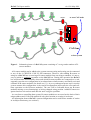
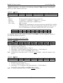
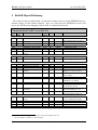
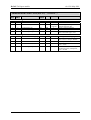
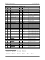
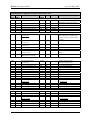
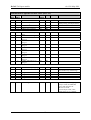
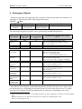
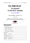
BsCAN CANopen module
v0.4 29-May-2001
BsCAN
CANopen B-sensor readout system
user manual, version 0.4
29 May 2001
Henk Boterenbrood
([email protected])
1
BsCAN CANopen module
v0.4 29-May-2001
Table of Contents
1
INTRODUCTION.............................................................................................................. 2
2
OPERATION...................................................................................................................... 4
2.1
2.2
2.3
INITIALISATION............................................................................................................... 4
CONFIGURATION............................................................................................................. 5
READ-OUT ...................................................................................................................... 6
3
BSCAN OBJECT DICTIONARY .................................................................................... 8
4
EMERGENCY OBJECTS .............................................................................................. 13
REFERENCES........................................................................................................................ 14
1 Introduction
The BsCAN CANopen application is a custom-made solution for reading out multiple 'addressable B-sensor modules' (described in [1]), using the CAN-bus and the CANopen protocol
([2]) for communication with a host system.
BsCAN is implemented on a CRYSTAL-CAN-V2 box (which has been slightly modified
for this application), a general-purpose microcontroller module with CAN-interface and eight
SPI (Serial Peripheral Interface) connectors for linking up to external I/O.
The CRYSTAL-CAN-V2 module is built around a 16-MHz Philips 80C592 8-bit microcontroller with on-chip CAN controller. It provides 48 kByte of user program memory and
63.5 kByte of user RAM [1]. Program code (in standard Intel Hex format) can be downloaded
directly via the RS232 port (which is accessible only after opening the box).
The BsCAN box can have up to 8 strings of B-sensor modules connected to its SPI connectors. A string is one (10-wire flat-)cable with one or more B-sensor modules. A special
adapter module is needed between the B-sensor cable and the CRYSTAL-CAN's SPIconnector. It provides the proper connector conversion and signal buffering.
The number of B-sensor modules connected to one string and to one BsCAN box is only
limited by electrical conditions and in practice means that up to about 10 B-sensor modules
can be connected to one string, and a total of up to 30 to 40 B-sensor modules can be connected to one BsCAN box. A string can have a length of up to about 15 meter (preliminary
information; tested and working is a cable of 10 meters with 10 B-sensor modules).
See Figure 1 for an example of a BsCAN system configuration.
A requirement is that the B-sensor modules connected to one BsCAN box must have a
unique address. The address of a B-sensor is printed on a sticker on the board and is a number
that lies between 0 and 127. This address is stored on-board in non-volatile memory (for details see [1]).
2
BsCAN CANopen module
v0.4 29-May-2001
adapter
to next CAN-node
adapter
adapter
CRYSTAL-CAN-V2
CAN-bus
to host system
Figure 1. Schematic picture of a BsCAN system consisting of 3 strings and a number of Bsensor modules.
A B-sensor module can be added to the system onto any string and a string can be connected
to any of the 8 CRYSTAL-CAN-V2 SPI connectors. However, after adding B-sensors or
strings to a BsCAN box (or moving a B-sensor module from one string to another) it is necessary to initiate a configure operation on the BsCAN box. During this operation the BsCAN
box will determine automatically where and which B-sensor modules are connected to it, subsequently store the new configuration in its onboard non-volatile memory and finally reset and
calibrate all B-sensor modules (for details see [1]). At every subsequent power-up or reset the
system assumes this configuration is the current configuration (and repeat the reset and calibrate operation on the B-sensor modules). The user will be informed about any B-sensor
modules missing (or not functioning) or having changed string position. Added B-sensors are
ignored and are not read out until after the next configure operation.
As seen from a controlling host system, B-sensor modules are accessed on the basis of their
unique address and CAN-node module-id only, their location on a string is irrelevant.
All information about a BsCAN's current configuration can be read from a number of entries
in its Object Dictionary (see section 3).
3
BsCAN CANopen module
v0.4 29-May-2001
2 Operation
2.1
Initialisation
Important:
• When powering up the system it should be switched off and immediately after switched on again: due to a hardware bug in the B-sensor microcontroller (Atmel AT90LS2343) the program in the microcontroller does not start
up at the first power-up: it needs to be powered off and on for the on-chip
RC oscillator to start running !
After power-up, watchdog reset, manual reset or CANopen initiated reset actions a CANopen
node sends a so-called Bootup message (a Network ManagemenT (NMT) message defined in
the CANopen standard) as soon as it has finished initialising (which takes a couple of seconds); this is a CAN-message with the following syntax:
BsCAN (NMT-Slave)
→
Host (NMT-Master)
COB-ID
0x700 + NodeID
Byte 0
0
The COB-ID is the Communication Object Identifier, the 11-bit CAN-message identifier defining one unit of transportation in a CAN network.
The NodeID is the CAN node identifier set by means of the CRYSTAL-CAN-V2 switches
(accessible on the frontpanel), which must be in the range between 1 and 127.
To simplify matters, after power-up or reset the BsCAN node automatically goes into Operational state, and the host application can immediately start reading out the B-sensor modules,
by sending CANopen SYNC messages (see section 2.3 for details).
Note that the CANopen standard defines that after power-up/reset a node goes into Preoperational state. Before any input channels can be read using the PDO mechanism, the connected CANopen-nodes have to be set into the Operational state. If for any reason the BsCAN
node has been set into another state (see [2]) other than Operational, it can be set into the Operational state using the 2-databyte NMT message shown below. There is no reply from the
node to this CAN-message.
Host (NMT-Master) → BsCAN (NMT-Slave)
COB-ID
0x000
Byte 0
1
(Start_Remote_Node)
Byte 1
Node-ID or 0
(all nodes on the bus)
4
BsCAN CANopen module
2.2
v0.4 29-May-2001
Configuration
To trigger the BsCAN node to probe its strings for B-sensor modules and store the newly
found configuration to non-volatile memory, a CANopen SDO (Service Data Object) message
must be send to read Object 5000h, subindex 0 (see the Object Dictionary in section 3). All Bsensors found are subsequently reset and calibrated. The reply message sent has one significant databyte, containing the total number of B-sensor modules found.
Here is a description of these CAN-messages, the SDO-client (request from host) and SDOserver (reply from BsCAN) CAN-message:
→
BsCAN
Byte
COB-ID
0
0x600+
0x40
NodeID
Host
1
0x00
2
0x50
3
0x00
4
–
5
–
6-7
–
Assuming everything went well and the number of B-sensor modules found is 30 (2Dh),
BsCAN replies with the following message:
BsCAN → Host
Byte
COB-ID
0
0x580+
0x4F
NodeID
1
0x00
2
0x50
3
0x00
4
0x2D
5
–
6-7
–
A full probing operation (scanning 8 strings, each for addresses 0 to 127) takes approximately 10 seconds to complete, also depending on the number of modules found.
If for any reason an SDO-client request from the host fails BsCAN replies with a so-called
SDO Abort Transfer message; this message has the following syntax:
→
Host
Byte
COB-ID
0
1
0x580+ 0x80 index
NodeID
(LSB)
BsCAN
2
index
(MSB)
3
subindex
4-7
Abort Code
See Table 1 below for a description of some Abort Codes (see also [2]).
5
BsCAN CANopen module
Abort Code
0503 0000
0504 0000
0601 0000
0602 0000
0606 0000
0609 0011
0800 0000
v0.4 29-May-2001
Description
Toggle bit not alternated
SDO protocol timed out
Unsupported access to an object
Object does not exist in the Object Dictionary
Object access failed due to a hardware error
Sub-index does not exist
General error
Table 1. SDO Abort Domain Transfer: descriptions of some Abort Codes (in byte 4-7).
2.3
Read-out
To trigger the read-out of all connected B-modules (their 3 Hall-sensors and 1 T-sensor) a
socalled SYNC message must be send.
The SYNC message is a CAN-message with a fixed COB-ID and no data bytes:
Host
→
all (SYNC-)slave nodes
COB-ID
0x080
After receiving this message the BsCAN node starts up a sequence of AD-conversions on all
B-sensor modules simultaneously to convert the H1, H2 and H3 Hall-sensors and the Tsensor, and subsequently reads out the converted analog inputs and sends them one-by-one in
a message on the CAN-bus.
Strings are scanned for data from BsCAN string connector 0 to connector 7, and B-sensor
modules on one string are scanned from the lowest to the highest B-sensor module address.
Per B-sensor module the messages arrive in the order H1, H2, H3 and T respectively.
In practice this means that after a conversion sequence is started (a SYNC message is received by the BsCAN node) it takes about 4*80=320 ms for the conversion sequence to complete and the first message arrives (for an AD-conversion wordrate of 15 Hz). The 4 messages
from one B-sensor module are about 1.5 ms apart. The time between the last message of one
B-sensor module and the first message of the next B-sensor module is about 5 ms.
For example: read-out of 32 B-sensor modules on 4 strings by one BsCAN box takes about
4*80 + 4*5 + 32*1.5 ms, which is roughly about 0.4 seconds from start to finish…
The message containing an ADC value is called a TPDO (Transmit Process Data Object)
in CANopen jargon, which is a message without any further CANopen protocol overhead. The
data bytes in the message contain application data only.
6
BsCAN CANopen module
v0.4 29-May-2001
BsCAN will produce –per channel– the following 6-databyte TPDO message containing the
data for one ADC channel conversion:
BsCAN → Host
TPDO COB-ID
Byte 0
0x280+NodeID
Address
with:
Address:
Chan no:
ADC value:
ADC-config:
BIT
Meaning
Byte 1
Chan no
Byte 2
ADC-config
Byte 3-5
ADC value
B-sensor module address (between 0 and 127).
0 = Hall H1, 1 = Hall H2, 2 = Hall H3, 3 = T-sensor.
24-bits value, LSB in byte 3, MSB in byte 5.
bit 7: not used.
bits 6-0: ADC configuration: conversion word rate (bits W0, W1 and W2),
gain range (bits G0, G1 and G2) and unipolar or bipolar (bit U/B); see below. For definitions see OD index 3000h-307Fh, sub 2,3,4,5,6 and 7.
7
-
6
W2
5
W1
4
W0
3
G2
2
G1
1
G0
0
U/B
(NB: BsCAN supports other modes of readout for this PDO (e.g. timer-triggered), but this is
not further described in detail here).
Example messages with ADC data:
BsCAN → Host
TPDO COB-ID
Byte 0
Byte 1
Byte 2
Byte 3
Byte 4
Byte 5
0x290
0x13
0x02
0x00
0xB0
0xD6
0xFF
This is a message from BsCAN node 16 (NodeID=0x290-0x280=0x10, see COB-ID):
• B-sensor 19 (=0x13, Byte 0)
• Hall-sensor H2 (channel number 2, Byte 1)
• Gain range = 100 mV bipolar, conversion word rate = 15.0 Hz (Byte 2)
• 24-bit ADC-value -10576 (=0xFFD6B0, Byte 3+4+5)
Note: a Hall-sensor conversion value is a 24-bit signed number ! (note the negative value
above)
BsCAN → Host
TPDO COB-ID
Byte 0
Byte 1
Byte 2
Byte 3
Byte 4
Byte 5
0x290
0x13
0x03
0x0B
0x26
0x6B
0x98
This is a message from BsCAN node 16 (NodeID=0x290-0x280=0x10, see COB-ID):
• B-sensor 19 (=0x13, Byte 0)
• T-sensor (channel number 3, Byte 1)
• Gain range = 2.5 V unipolar, conversion word rate = 15.0 Hz (Byte 2)
• 24-bit ADC-value 624306 (=0x986B26, Byte 3+4+5)
Note: a T-sensor conversion value is a 24-bit unsigned number !
7
BsCAN CANopen module
v0.4 29-May-2001
3 BsCAN Object Dictionary
The values of objects marked with ∗ in the Index column can be saved in EEPROM for permanent storage in non-volatile memory. They are retrieved from EEPROM at reset and
power-up (The B-sensor mapping, Object 4300, is automatically stored).
Communication Profile Area (BsCAN)
Index
(hex)
Sub
Index
Name
Data/
Object
Attr
1000
-
Device type
U32
RO
00040191h
1001
1002
-
Error register
Manufacturer status reg
U8
U32
RO
RO
0
0
1008
1009
100A
-
Manufacturer device name
Manufacturer hw version
Manufacturer software
version
VisStr
VisStr
VisStr
RO
RO
RO
"CRYS"
"CRY2"
"BC10"
100C
100D
*
-
Guard time [ms]
Life time factor
U16
U8
RO
RW
1000
0
Store parameters
Highest index supported
Save all parameters
Save communication parameters
Save application par's
Array
U8
U32
U32
RO
RW
RW
3
1
1
U32
RW
1
Restore default parameters
Array
0
1
Highest index supported
Restore all parameters
U8
U32
RO
RW
3
1
2
Restore communication
parameters
Restore application par's
U32
RW
1
U32
RW
1
Producer Heartbeat Time
[1 ms]
U16
RO
0
Identity
Number of entries
Vendor ID
Record
1..4
U32
RO
RO
1
12345678h
1010
0
1
2
3
1011
3
1017
*
-
1018
0
1
1
Default
Comment
Meaning: DSP-401 device profile, analogue inputs on device
1
(see footnote)
= CRYSTAL-CAN
= CRYSTAL-CAN-V2
BsCAN application v1.0
= 1 second
0 → no lifeguarding timeout
Save stuff in onboard EEPROM
Read: 1; Write "save": store all
Read: 1; Write "save": store
PDO par's, Life time factor, …
Read: 1; Write "save": store
ADC config, …
Invalidate stuff in onboard
EEPROM; use defaults
Read: 1; Write "load": invalidate
all parameters stored
Read: 1; Write "load": invalidate stored PDO par's, etc.
Read: 1; Write "load": invalidate stored ADC config, etc.
Truncated to multiples of 1000;
= 30 s, if Heartbeat enabled
Mandatory CANopen object
Manufacturer Status Register: status for B-sensor modules #0 to #31;
1 bit per module: 0=OKAY, 1=Error/Absent.
8
to be ordered from CiA
BsCAN CANopen module
v0.4 29-May-2001
Communication Profile Area (BsCAN) (continued…)
Index
(hex)
Sub
Index
Name
Data/
Object
Attr
Default
0
1
2nd Transmit PDO par's
Number of entries
COB-ID used by PDO
Record
U8
U32
RO
RO
Transmission type
Inhibit time [100 µs]
Event timer [1 ms]
U8
U16
U16
RW
RO
RW
5
280h +
NodeID
1
0
0
2
3
5
0
2nd Transmit PDO mapping
Number of entries
Record
U8
RO
3
1
2
B-sensor/ADC address
B-sensor channel number
U32
U32
RO
RO
40000008
30000108
3
24-bit analogue input
U32
RO
40xx0y18
1801
*
*
1A01
Comment
Data type = PDOCommPar
9
According to CANopen Predefined Connection Set
Only 1 and 255 allowed
not used
Truncated to multiples of 1000;
active if transm-type = 255
Data type = PDOMapping
should be 255 for MuxPDO, but
this is not a CANopen MPDO…
actually not allowed, but…
OD-index 3000, sub-index 1:
size = 8 bits
OD-index 40xx, sub-index y:
Analogue inputs, multiplexed,
size = 24 bits
BsCAN CANopen module
v0.4 29-May-2001
Manufacturer-specific Profile Area (BsCAN)
Index
(hex)
Sub
Index
Name
Data/
Object
Attr
Default
8
9
10
11
12
13
14
15
16
17
18
B-sensor #0 ADC-config
Number of entries
Number of input channels
Conversion Word Rate
Hall-sensors
Input Voltage Range Hall
Unipolar/Bipolar
Measurement Mode Hall
Conversion Word Rate
Temperature sensor
Input Voltage Range Temp
Unipolar/Bipolar
Measurement Mode Temp
Power Save Mode
Configuration Register
Offset Register #1
Gain Register #1
Offset Register #2
Gain Register #2
Offset Register #3
Gain Register #3
Offset Register #4
Gain Register #4
Channel-Setup Register #1
Record
U8
U8
U8
RO
RO
RW
21
7
0
U8
U8
RW
RW
0
0
U8
RW
0
U8
U8
RW
RW
0
0
Bool
U32
U32
U32
U32
U32
U32
U32
U32
U32
U32
WO
RW
RW
RW
RW
RW
RW
RW
RW
RW
RW
19
Channel-Setup Register #2
U32
RW
20
Channel-Setup Register #3
U32
RW
21
Channel-Setup Register #4
U32
RW
B-sensor #1 ADC-config
Record
…
…
B-sensor #2 ADC-config
Record
etc
…
…
…
…
…
…
…
…
B-sensor #127 ADC-config
Record
…
…
…
NB: some settings are global for
all B-sensor modules !
…
3000
*
0
1
2
*
*
3
4
*
5
*
*
6
7
3001
etc
3002
…
307F
etc
Comment
CRYSTAL CS5524 24-bit ADC
…
(Global setting!)
3-bit code 2 (Global setting!)
0 = bipolar, 1 = unipolar
(Global setting!)
3-bit code 1 (Global setting!)
3-bit code 2 (Global setting!)
0 = bipolar, 1 = unipolar
(Global setting!)
1 = power save
CS5523 Config Register
CS5523 physical channel AIN1
CS5523 physical channel AIN1
CS5523 physical channel AIN2
CS5523 physical channel AIN2
CS5523 physical channel AIN3
CS5523 physical channel AIN3
CS5523 physical channel AIN4
CS5523 physical channel AIN4
LC 1 (12-bits) in lower 2 bytes,
LC 2 (12-bits) in upper 2 bytes
LC 3 (12-bits) in lower 2 bytes,
LC 4 (12-bits) in upper 2 bytes
LC 5 (12-bits) in lower 2 bytes,
LC 6 (12-bits) in upper 2 bytes
LC 7 (12-bits) in lower 2 bytes,
LC 8 (12-bits) in upper 2 bytes
…
NB: some settings are global for
all B-sensor modules !
…
…
NB: some settings are global for
all B-sensor modules !
…
…
1
000: 15.0 Hz,
100: 101.1 Hz,
001: 30.0 Hz,
101: 1.88Hz,
010: 61.6 Hz,
110: 3.76 Hz,
011: 84.5 Hz,
111: 7.51 Hz
2
000: 100 mV,
001: 55 mV,
010: 25 mV,
011: 1 V,
10
3-bit code 1
100: 5 V,
101: 2.5 V
BsCAN CANopen module
v0.4 29-May-2001
Manufacturer-specific Profile Area (BsCAN)
Index
(hex)
Sub
Index
Name
Data/
Object
B-sensor module status
Record
Number of entries
status B-sensors #0-#31
status B-sensors #31-#63
status B-sensors #63-#95
status B-sensors #96-#127
U8
U32
U32
U32
U32
RO
RO
RO
RO
RO
3200
ADC-reset-and-calibrate
B-sensor #0
U8
WO
3201
ADC-reset-and-calibrate
B-sensor #1
ADC-reset-and-calibrate
B-sensor #2
…
…
ADC-reset-and-calibrate
B-sensor #127
ADC-reset-and-calibrate
all B-sensors in config
U8
WO
Writing any value triggers a reset
and calibration sequence on Bsensor #0 with its current ADC
settings
reset+calib of B-sensor #1 ADC
U8
WO
reset+calib of B-sensor #2 ADC
…
…
U8
…
…
WO
…
…
reset+calib of B-sensor #127
ADC
U8
WO
3100
0
1
2
3
4
3202
…
…
327F
…
…
3280
4000
0
1
2
3
4
5
6
7
0
1
…
7
Read analogue input
B-sensor #1
Number of entries
Input 1
…
Input 7
U8
I24
…
I24
RO
RO
…
RO
…
…
…
…
…
…
…
…
Record
0
1
…
7
Read analogue input
B-sensor #127
Number of entries
Input 1
…
Input 7
407F
Default
4
0xfffffff
0xfffffff
0xfffffff
0xfffffff
Record
U8
I24
I24
I24
I24
I24
I24
I24
24 bits analogue value
(B-sensor address #0)
RO
RO
RO
RO
RO
RO
RO
RO
7
Record
U8
I24
…
I24
Comment
Error status, one bit per B-sensor
0=OKAY, 1=Error or Absent
Read analogue input
B-sensor #0
Number of entries
Input 1: Hall-sensor H1
Input 2: Hall-sensor H2
Input 3: Hall-sensor H3
Input 4: current sense
Input 5: NTC T-sensor
Input 6: 0ºC calib input
Input 7: 100ºC calib input
4001
…
…
Attr
1st analog input:24-bit
2nd "
"
"
3rd "
"
"
4th "
"
"
5th "
"
"
6th "
"
"
7th "
"
"
24 bits analogue value
(B-sensor #1)
7
1st analog input:24-bit
…
7th "
"
"
…
…
24 bits analogue value
(B-sensor #127)
RO
RO
…
RO
11
7
1st analog input:24-bit
…
7th "
"
"
BsCAN CANopen module
v0.4 29-May-2001
Manufacturer-specific Profile Area (BsCAN)
Index
(hex)
Sub
Index
4100
Name
Data/
Object
Attr
0
B-sensor address list
Total number of B-sensors
U8
RO
1
…
n
Address of 1st B-sensor
…
Address of n th B-sensor
U8
…
U8
RO
…
RO
Number of B-sensors per
string
Total number of strings
Number of B-sensors on
string #0
Number of B-sensors on
string #1
Number of B-sensors on
string #2
Number of B-sensors on
string #3
Number of B-sensors on
string #4
Number of B-sensors on
string #5
Number of B-sensors on
string #6
Number of B-sensors on
string #7
Array
4200
0
1
2
3
4
5
6
7
8
U8
U8
RO
RO
U8
RO
U8
RO
U8
RO
U8
RO
U8
RO
U8
RO
U8
RO
4300
*
0
B-sensor-to-string mapping
string# with B-sensor #0
Array
U8
RO
*
*
*
*
1
2
…
127
string# with B-sensor #1
string# with B-sensor #2
…
string# with B-sensor #127
U8
U8
…
U8
RO
RO
…
RO
5000
-
Probe strings for B-sensors
RO
12
Default
Comment
= number of modules found
when probing (see Object 5000)
…
8
value 0xFF means: this B-sensor
not found in any of the strings
"
"
…
"
stores newly found mapping
(Object 4300) in EEPROM;
resets and calibrates all
B-sensors found;
returns Object 4100, sub 0;
takes about 10 s to complete.
BsCAN CANopen module
v0.4 29-May-2001
4 Emergency Objects
Emergency messages are triggered by the occurrence of an internal (fatal) error situation. An
emergency CAN-message has the following general syntax:
BsCAN → Host
COB-ID
Byte 0-1
080h +
Emergency
Error Code
NodeID
Byte 2
Error Register
(Object 0x1001)
Byte 3-7
Manufacturer specific error field
The following Emergency messages can be generated by the BsCAN application:
Error
Description
Emergency
Error Code
Error Register
bit (Object 1001H)
Manufacturer-specific Error Field
(byte 3-7)
(byte 0-1)
(byte 2)
CAN communication
8100
10
Byte 3: 81C91 Interrupt Register content
Byte 4: 81C91 Mode/Status Register content
Byte 5: error counter
Life Guarding
8130
10
(CAN-controller has been reinitialized)
EEPROM:
write failed
5000
80
EEPROM:
read error
5000
80
Byte 3: 41
Byte 4: Parameter block index 1
Byte 5: 0 : writing block info
> 0: size of parameter block to write
Byte 3: 42
Byte 4: Parameter block index 2
Byte 5: Error id (1=CRC, 2=length, 4=infoblock)
B-sensor ADC:
conversion
timeout
B-sensor ADC:
reset failed
5000
80
5000
80
B-sensor ADC:
offset calibration failed
B-sensor ADC:
gain calibration
failed
B-sensor ADC
problem(s) during initialisation
5000
80
5000
80
Byte 3: 54
Byte 4: B-sensor address (0..127)
5000
80
Byte 3: 55
Byte 3: 51
Byte 4: B-sensor address (0..127)
Byte 5: ADC channel number (0..3)
Byte 3: 52
Byte 4: B-sensor address (0..127)
Byte 5: Error id 3
Byte 3: 53
Byte 4: B-sensor address (0..127)
Note that the Error Register (Object Dictionary index 0x1001) can have one or more of the
bits shown above set, depending on the node's history of errors since the last reset. The table
shows the Error Register bit that gets additionally set when the corresponding error occurs.
1
2
3
0: PDO communication parameters, 1: Guarding parameters, 2: ADC configuration, 3: Bsensor-to-string mapping
idem
01: Reset-Valid bit not set, 02: Reset-Valid bit not reset, 04: error in Offset Register value,
08: error in Gain Register value
13
BsCAN CANopen module
v0.4 29-May-2001
References
[1] H.Boterenbrood,
B-sensor with addressable Serial Peripheral Interface,
Version 1.3, NIKHEF, Amsterdam, 27 March 2001.
(http://www.nikhef.nl/pub/departments/ct/po/html/Bsensor/Bsensor.pdf
[2] H.Boterenbrood,
CANopen, high-level protocol for CAN-bus,
Version 3.0, NIKHEF, Amsterdam, 20 March 2000.
(http://www.nikhef.nl/pub/departments/ct/po/doc/CANopen30.pdf).
[3] CRYSTAL CS5521/22/23/24/28, 16-Bit or 24-bit, 2/4/8-Channel ADCs with
PGIA, CIRRUS LOGIC product datasheet, DS317F2, May 2000,
(http://www.cirrus.com).
14