1
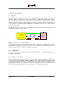
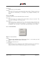
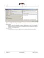
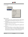
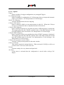
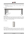
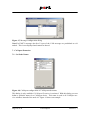
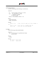
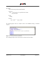
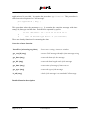
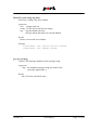
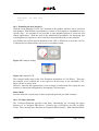
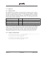
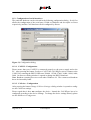
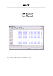
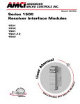
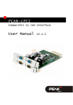
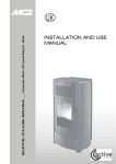
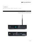
CAN-REport
User Manual
© port GmbH, Halle 07.09.2004; CAN-REport Version 3.1
Disclaimer
All rights reserved
The programs, boards and documentations supplied by port GmbH are created with due
diligence, checked carefully and tested on several applications.
Nevertheless, port GmbH can not take over no guarantee and no assume del credere liability that the program, the hardware board and the documentation are error-free respective are suitable to serve the special purpose.
In particular performance characteristics and technical data given in this document may
not be constituted to be guaranteed product features in any legal sense.
For consequential damages, which are emerged on the strength of use the program and
the hardware boards therefore, every legal responsibility or liability is excluded.
port has the right to modify the products described or their documentation at any time
without prior warning, as long as these changes are made for reasons of reliability or
technical improvement.
All rights of this documentation lie with port. The transfer of rights to third parties or
duplication of this document in any form, whole or in part, is subject to written approval
by port. Copies of this document may however be made exclusively for the use of the
user and his engineers. The user is thereby responsible that third parties do not obtain
access to these copies.
The soft- and hardware designations used are mostly registered and are subject to copyright.
We are thankful for hints of possible errors and may ask around for an information.
We will go all the way to verify such hints fastest
Copyright
© 2005 port GmbH
Regensburger Straße 7
D-06132 Halle
Tel. +49 345 - 777 55 0
Fax. +49 345 - 777 55 20
E-Mail [email protected]
Internet http://www.port.de
Page 2 of 42
CAN-REport
Version: 3.1
Table of Contents
1. Overview . . . . . . . . . . . . . . . . . . . . . . . . . . . .
5
2. Installation
.
6
3. Application . . . . . . . . . . . . . . . . . . . . . . . . . . .
6
4. Interfacing with CAN
.
8
5. Graphical User Interface . . . . . . . . . . . . . . . . . . . . . .
10
6. Interpretation of CAN messages
.
19
7. CANopen-Extension . . . . . . . . . . . . . . . . . . . . . . . .
20
8. Trigger . . . . . . . . . . . . . . . . . . . . . . . . . . . . .
21
9. Filter . . . . . . . . . . . . . . . . . . . . . . . . . . . . . .
24
10. Programming with CAN-REport . . . . . . . . . . . . . . . . . . .
26
10.1. Extending CAN-REport
.
26
10.2. Interpretation of CAN messages . . . . . . . . . . . . . . . . . .
29
10.3. Extending the user interface . . . . . . . . . . . . . . . . . . . .
35
10.4. CANopen functions . . . . . . . . . . . . . . . . . . . . . . .
35
11. Configuration . . . . . . . . . . . . . . . . . . . . . . . . . .
39
Configuration of serial interfaces . . . . . . . . . . . . . . . . . . . .
40
12. System Requirements . . . . . . . . . . . . . . . . . . . . . . .
41
13. Purchase Order Information
41
Version: 3.1
.
.
.
.
.
.
.
.
.
.
.
.
.
.
.
.
.
.
.
.
.
.
.
.
.
.
.
.
.
.
.
.
.
.
.
.
.
.
.
.
.
.
.
.
.
CAN-REport
.
.
.
.
.
.
.
.
.
.
.
.
.
.
.
.
.
.
.
.
.
.
.
.
.
.
.
.
.
.
.
.
.
.
.
.
.
.
.
.
.
.
.
.
.
.
.
.
.
.
.
.
.
.
.
.
.
.
.
.
.
Page 3 of 42
Page 4 of 42
CAN-REport
Version: 3.1
1. Overview
The CAN-Analyzer CAN-REport from port is an efficient and versatile usable instrument
for development, test and maintenance, for analysis and commissioning of CAN-based
networks like DeviceNet and CANopen.
The built-in scripting capability allows a universal usage for development and test of
CAN devices besides the normal possibilities of displaying the received CAN messages.
It is especially useful in the field of industrial CAN networking.
The separation of hardware-interface (CAN access) and visualization software allows the
usage in TCP/IP networks.
Figure 1, Analyzer view
Version: 3.1
CAN-REport
Page 5 of 42
2. Installation
The installation includes:
• the graphical user interface
• the horch server and
• a layer 2 driver for the CAN interface.
For the installation the following steps are necessary:
1.
Maybe preparing installation steps are necessary depending on the used CANInterface. These steps are described in the file INSTALL in the horch directory on
the installation CD.
!
2.
Please read this file before you start the installation.
Execute setup.exe.
• Full Installation: The installation of all software components is happened automatically and menu driven. This includes copying of all manuals.
• Customized Installation: The selection of software components is possible, which
should be installed. For the installation of the CAN-REport the following components are necessary: CAN-REport, horch and layer 2 driver.
3.
For the icon on the desktop set the options for the call of the horch server depending on your application. An overview of the options are given by the help:
horch -h
3. Application
In the standard equipment the CAN-Analyzer already has a lot of efficient basic functions
at its disposal, which cover most application needs.
Among other things the on-line observation of the bus traffic, the transmitting of unique
or cyclical CAN messages and whole message sequences as well as the recording of
CAN messages and the storage to log files belong to this purpose. Besides the standard
text format, we also support the CSV format for easy data transfer into spread sheet applications.
Application specific interpretation of the messages’ data content can be defined through a
project specific data base.
Through supplementary software modules extended functionality can be made available.
These are among other things the protocol-specific representations in separate protocol
windows for different higher layer protocol messages. Figure 2 shows this for SDO messages in CANopen-based networks.
Page 6 of 42
CAN-REport
Version: 3.1
Figure 2, CANopen SDO interpretation and recording
You can see the symbolic representation of service and node name, "Req_Verriegelung",
as well as displaying of "index:subindex" within the SDO Initiate requests.
With the help of the built-in scripting language programming of new functions or individual extensions with a graphic interface can be programmed easily.
Version: 3.1
CAN-REport
Page 7 of 42
4. Interfacing with CAN
4.1. TCP/IP
The analyzer CAN-REport consists of the CAN hardware interface and the visualization
software. Both are connected as server and client by a standard TCP/IP network connection. This separation allows the usage of the CAN interface as a remote interface. That
means both parts can be located at different computer systems. Remote monitoring of
CAN networks is possible without additional or modified software over LAN, dial or
internet connections.
The Horch-protocol is used as a communication protocol between operating-client and
hardware-server on top of TCP/IP.
CAN-bus
TCP-IP
CAN-Report
visualisation
Internet
Internet
application program
Modem
Modem
CAN
hardware
interface
Figure 3, Client-Server communication
CAN interfaces are currently available for ISA, PCI, parallel port, serial, and PC104 with
MS-Windows operating systems, ISA and PCI for LINUX or as Ethernet-interface as
stand alone CAN-Server on the port-EtherCAN module.
4.1.1. CAN-Server
The CAN-Server horch is the interface from TCP/IP to CAN. A detailed description can
be found in its manual.
4.1.2. Client - CAN-REport
The visualization and operating software is based on the scripting language Tcl/Tk which
is available for many different computer platforms. The usage is therefore possible on all
systems supporting this language. Through separation of hardware CAN-Interface and
man-machine interface it is possible to use the CAN-REport besides MS-Windows on
LINUX or Macintosh computers for controlling the CAN hardware interface.
Page 8 of 42
CAN-REport
Version: 3.1
4.2. Serial Interfaces
Besides the client-server connections the CAN-REport supports also direct connections to
CAN-RS232 interfaces as:
• CAN232
• CANview
For further information about the configuration please have a look at the section Configuration of serial interfaces.
Version: 3.1
CAN-REport
Page 9 of 42
5. Graphical User Interface
The graphical user interface consists of 4 components.
5.1. Menubar
5.1.1. File Menu
Figure 4, File Menu
Open
Open a previously stored logfile. If the CANopen Extension is activated then the
contents can be interpreted as CANopen data.
Save
Save the contents of the main window into a file.
Exit
Exits CAN-REport.
Page 10 of 42
CAN-REport
Version: 3.1
5.1.2. Edit Menu
Figure 5, Edit Menu
Cut
Cut selected text into clipboard.
Copy
Copy selected text into clipboard.
Paste
Pastes text from clipboard into the main window.
Clear Log
Clears content of the main logging window.
Select All
Selects the whole content of the main logging window.
Find
Opens a standard find dialog box to search for text signatures.
5.1.3. View Menu
Figure 6, View Menu
Toolbar
Toggles the view of the toolbar.
Statusbar
Toggles the view of the statusbar.
Version: 3.1
CAN-REport
Page 11 of 42
Transmitbar
Toggles the view of the statusbar.
Console
Opens the Tcl-Tk console in the bottom of the main window. With the console you
can extend the functionality of CAN-REport See paragraph Extending CANREport.
5.1.3.1. View mode
CAN-REport possesses a trace mode and a object view mode.
Trace view
All CAN messages are written into the main window as they are received. The
view shows: timestamp, CAN-ID, type, data.
Object view
Each CAN message is placed in one line. Every time the message with the same
CAN identifier is received the line is updated. A maximum of 192 messages can
be displayed. The view shows: CAN-ID, type, data, period and a receive counter.
5.1.4. Connection Menu
Figure 7, Connection Menu
Connect
Connect to the CAN-Server horch All necessary data, i.e. server name, port and
bitrate, are input within the menu CAN-Interface.
Disconnect
Disconnect from the server.
CAN-Interface
Opens a dialog for the configuration of the TCP/IP connection to the CAN-Server.
Only the interfaces that are installed with a propriate driver are displayed.
Page 12 of 42
CAN-REport
Version: 3.1
Figure 8, Configuration dialog of CAN interface
Filter Settings
Opens a dialog for setting the acceptance mask register of the CAN controller.
Although this menu is provided not every hardware interface supports the setting of
registers. See paragraph Filter.
Only Log to File
CAN messages are saved to a logfile and are not displayed in the main window.
Version: 3.1
CAN-REport
Page 13 of 42
5.1.5. Extras Menu
Figure 9, Extras Menu
CANopen Extension
Loads the CANopen extension. If switched on the toolbar is extended by buttons
for the CANopen services SDO, PDO, NMT, EMCY, FLYMA. When clicking on
a button a windows pops up and displays the CAN message of its service.
DeviceNet Extension
Loads the DeviceNet extension. If switched on the toolbar is extended with a button for the DeviceNet log window. When clicking on a button a window pops up
and displays a descriptive text for the message.
User Extension
Loads the file <application.tcl> and adds a button to the toolbar. This file provides
a Tcl-function for user-defined protocol interpretation. An example file is provided.
Maritime Extension
Loads the maritime Extension. It is used for monitoring 2 CAN lines at a time.
Therefore it needs to connect to two CAN-servers. When the extension is activated
it closes the current connection. The CAN-Interface dialog now provides input
fields to connect to two CAN-servers. The main window displays the CAN messages from both lines. The transmitbar is changed in that the checkbuttons for
extended messages and RTR messages now are used for selecting the line.
Page 14 of 42
CAN-REport
Version: 3.1
5.1.5.1. Options
Trigger
Opens a window for trigger configuration (see paragraph Trigger).
User Mapping Settings
Opens a window for configuration of CAN messages that are interpreted automatically by CAN-REport. See Interpretation of CAN messages.
Enable User Mapping
Activates and deactivates the user mapping.
CANopen Node Names
Opens a dialog in which you can assign names to node id’s. When the CANopen
extension is on then this name is displayed instead of the node id.
CANopen PDO Mapping
Opens a dialog in which you can define how data of PDO messages is interpreted.
The mapping specifies the COB-ID, symbolic name of the PDO and pairs of data
type and symbolic name for the data. See Interpretation of CAN messages.
CANopen EMCY Mapping
Opens a dialog in which you can define how data of EMCY messages is displayed.
The mapping specifies the COB-ID, symbolic name of the EMCY and pairs of data
type and symbolic name for the data. See Interpretation of CAN messages. See
Interpretation of CAN messages.
CANopen interpretation in main window
Activates CANopen interpretation in the main window.
Connect at Startup
This option controls the startup behavior. When activated CAN-REport will try to
connect to the CAN server at the next start.
Tooltips
Activates tooltips for every button and input field.
Auto Save
If this menu is activated then the configuration is stored before exiting CANREport.
Version: 3.1
CAN-REport
Page 15 of 42
5.1.6. Window Menu
Figure 10, Window Menu
Clear All
Clear the content of the main window and of windows that are created of extensions.
Cascade
Place the extension windows cascaded next to the main window.
Tile Vertical
Place the extension windows vertical next to the main window.
Tile Horizontal
Place the extension windows horizontal under the main window.
Hide All
Hide all extension windows.
Show All
Show all extension windows.
5.1.7. Help Menu
Figure 11, Help Menu
Help
Provides a short help to CAN-REport.
About
Copyright and license information. Additionally it displays the Tcl/Tk packages
that are available.
Page 16 of 42
CAN-REport
Version: 3.1
Latest Release Info
Checks for the latest Release of CAN-REport. Therefore it establishes a TCP/IP
connection to http://www.port.de
5.2. Toolbar
Extension area
Toggle scrolling
Disconnect
Connect
Stop
WWW
Figure 12, Toolbar
The toolbar provides quick access to the menu items Connect and Disconnect. The third
button with the down arrow switches scrolling of the main window on or off. The stop
button is used for canceling user-defined scripts. Please see paragraph: Extending CANREport. With the "www"-button CAN-REport checks if a new version of CAN-REport is
available. Therefore it connects to the internet.
5.3. Statusbar
Figure 13, Statusbar
The Status shows information about the connection to the horch-Server. Additionally
there are buttons influence the display of the CAN messages in the main window. The
buttons "ASCII", "Hex" and "Dec" change the display of the data of a CAN message.
With the "toggle Time"-button the display of the receiving time can be switched on and
Version: 3.1
CAN-REport
Page 17 of 42
off. It is displayed in "seconds.microseconds". The indication of microseconds depends
on the driver. The linux driver can4linux supports a resolution of milliseconds. With the
button "Set Mark" a separation line is inserted in the main window.
The status button provides a window with information about the underlying CAN hardware and driver respectively. The figure 14 below shows the information of a CAN server
that is running on linux. Windows driver do not support all shown information. Therefore some values will always show 0.
Figure 14, Status window
5.4. Transmit Toolbar
CAN-REport also allows it to send CAN messages. In the transmit toolbar at the bottom
a complete CAN message can be specified with CAN id and CAN data With the button
"Send" the message is sent. The number of tabs can be set in the configuration file <canreport.rc> with:
set ST(txch) 12 ; #put any number here
The CAN messages are stored in the configuration file in the current working directory.
If "AutoSave" was activated CAN-REport will save the settings automatically at exit. At
the next start all your settings will be reloaded. Optionally a name can be assigned to a
CAN message. The edit fields take decimal, hexadecimal and octal values as input.
Hexadecimal values are prepended with "0x" and octal values with "0". If it is necessary
to send CAN messages periodically, then a "Repeat Time" in ms can be specified. The
CAN message sent is not displayed in the main window. Only a notification is shown. If
a "Repeat Time" was specified no notification is displayed.
Page 18 of 42
CAN-REport
Version: 3.1
Figure 15, Transmit Toolbar
6. Interpretation of CAN messages
This dialog is used for User-, PDO and EMCY-Mapping. PDO and EMCY mapping is
only available if the CANopen Extension is activated. PDO/EMCY-Mapping is used to
interpret CAN-messages with ID of the PDO (0x181 - 0x57F) and EMCY (0x81 - 0xFF)
range in a user specific way. The user mapping can be used for all other CAN messages.
The data contents can be interpreted as signed and unsigned integer values. Each data
item can be assigned to a user specific text and the data format ("big endian", "little
endian") can be selected. Configuration is done with two dialogs. First there is an overview dialog that shows all configured messages. Second there is the message configuration dialog.
Figure 16, PDO/EMCY-Mapping dialog
The dialog has buttons to add, edit and delete messages that should be interpreted. On
press of the add and edit button the message configuration dialog opens.
Version: 3.1
CAN-REport
Page 19 of 42
Figure 17, Message configuration dialog
Note:For EMCY messages the first 3 bytes of the CAN message are predefined as u16
and u8. This is not displayed and cannot be altered.
7. CANopen-Extension
7.1. Set Node Names
Figure 18, CANopen configuration of CANopen node names
This dialog is only available if CANopen Extension is activated. With this dialog you can
define a symbolic name for a CANopen device. This name is used is all CANopen service windows instead of the node id. Figure 19 shows an example.
Page 20 of 42
CAN-REport
Version: 3.1
Figure 19, CANopen PDO interpretation and recording
7.2. "Service oriented interpretation"
The CANopen extension provides separate logging windows for the services: NMT,
SDO, PDO, EMCY and Flying Master (FLYMA).
The interpretation for PDO and EMCY can be tailored alike the user mapping for the specific application.
8. Trigger
With the trigger functionality CAN-REport is able to wait for certain CAN messages and
continue recording after the desired message was received.
Trigger Event
-
Action at trigger event
-
Logfile options
-
Specifies the CAN message with its contents
to wait for. With the help of the CANopen
Message Builder it is easy to create CAN messages which conform to the CANopen protocol.
Select what to do when the specified CAN
message was received. CAN messages can be
displayed in the main window or save in a logfile.
Determine what else CAN-REport should do
when writing to a logfile and specified the
CAN messages were received.
Table 1, Sections of the trigger dialog
Version: 3.1
CAN-REport
Page 21 of 42
Figure 20, Trigger dialog
The process of triggering is started with the button "Start Trigger". During the trigger
process the dialog stays on top of the application and recording of messages in the main
window stops. After the specified CAN message was received the trigger dialog disappears.
8.1. Defining a trigger CAN message
Up to three different CAN message can be specified as trigger events. The second and
third CAN message are activated through the checkbutton labeled "active". The first
CAN message is active by default. The input in the fields CAN-ID and data can be specified as decimal, hexa-decimal or octal numbers. Hexa-decimal numbers are prepended
with "0x" and octal numbers with "0". A blank input field determines the end of the
CAN message. Any data byte after a blank input field is ignored. The length is then calculated by the number of non empty input fields. In order to ignore the contents of a byte
mark it as don’t care by entering an "X" into an edit field instead of a numerical value.
Then its value is not compared with the received message.
Examples:
Page 22 of 42
CAN-REport
Version: 3.1
Figure 21, Trigger example 1
CAN message with 8 bytes length. Byte 4 to 7 are marked as don’t care. Numbers used
in decimal hexadecimal and octal
Figure 22, Trigger example 2
CAN message with 5 bytes length. Byte 4 and 5 are marked as don’t care. Numbers
used in decimal hexadecimal and octal
Figure 23, Trigger example 3
Only the CAN-id is compared. The content and length of the CAN message is not evaluated.
8.2. Defining a trigger Remote Request CAN message
Defining a Remote Request CAN message follows the same rules as a "normal" CAN
messages. Setting the expected length of the RTR message is done with the don’t care
bytes. Example:
Figure 24, Trigger example 4
The CAN-REport triggers on a RTR message with CAN id 0x64 and a length of 5 bytes.
8.3. CANopen Message Builder
The CANopen Message Builder eases creating of CAN messages for the trigger which
conform to the CANopen protocol. It provides input masks for the CANopen services
NMT, PDO, SDO, HEARTBEAT and EMCY. Figure 25 shows the input mask for the
NMT service. The CANopen Message Builder is only available with the CANopen
Extension.
Version: 3.1
CAN-REport
Page 23 of 42
Figure 25, Input dialog for NMT service of the NMT service
9. Filter
Figure 26, Filter dialog
The filter dialog provides access to the register of the acceptance mask of the CAN controller SJA1000. The usage of acceptance filtering in the CAN-Controller reduces the
interrupt load. There are three ways of defining the acceptance mask:
1.
Input for the acceptance mask for CAN 2.0 A starting with the MSB on the left
side.
2.
Input of the acceptance mask for CAN 2.0 B starting with the MSB on the left side.
3.
Input of the acceptance mask as it is defined in the register of the CAN controller.
This feature depends on the hardware and driver respectively you are using. At the
moment the horch server for can4linux and CPC (SJA1000) support setting the acceptance mask registers. The other supported hardware interfaces (see Restrictions) don’t
support this.
Page 24 of 42
CAN-REport
Version: 3.1
Attention: Although it is possible to set the two least significant bits of the CAN identifier the SJA1000 doesn’t use these two bit during acceptance filtering.
Version: 3.1
CAN-REport
Page 25 of 42
10. Programming with CAN-REport
10.1. Extending CAN-REport
With the help of the integrated console convenient commands for the interactive access
on the CAN network are available and not only for device developers. These commands
can be used in test scripts. Commands like wr for the sending of messages or wait for
the synchronization with CAN messages on the network belong to this purpose.
Overview of user function
wait {id timeout}
- wait for CAN message with id or until timeout
wait2 {id type timeout}
- wait for CAN message with id and type or until timeout
wr {args}
- send CAN message with standard identifier
wrx {args}
- send CAN message with extended identifier
Detailed function description
wait {id timeout}
wait for CAN message with id or until timeout
this function is deprecated please use wait2
Arguments
id
- can be an integer, or hex (0x...) or "any"
timeout - in ms, defaults to 10000 == 10s
Results
String with message
String: "wait timeout"
Page 26 of 42
CAN-REport
Version: 3.1
wait2 {id type timeout}
wait for CAN message with id and type or until timeout
Arguments
id
- can be an integer, or hex (0x...) or "any"
type - any combination of s,x,D,R
s - standard; x extended
D - data; R - RTR
timeout - in ms, defaults to 10000 == 10s
Results
String with message
String: "wait timeout"
Example
wait2 12 R
or x
wait2 10 sR
wait2 any
; wait 12s for RTR ID of any format s
; wait 10s for standard RTR ID
; wait for the next message
wr {args}
send CAN message with standard identifier
Arguments
args - a CAN message. It is specified in the format
id [r] data-bytes
Results
nothing
Example
wr 0x620 r 0x30 0xff
wr 0x20
0x69 0x55
Version: 3.1
CAN-REport
Page 27 of 42
wrx {args}
send CAN message with extended identifier
Arguments
args - a CAN message. It is specified in the format
id [r] data-bytes
Results
nothing
Example
wrx 0x820 r 0x30 0xff
wrx 0x20
0x69 0x55
The following figure shows an example session at the console entering a command
sequence:
Figure 27, Entering interactive commands
The resulting messages at the CAN network are shown in the next figure:
Page 28 of 42
CAN-REport
Version: 3.1
Figure 28, Results of the commands of figure 4
The commands can be combined into sequences or procedures. All semantics of modern
high level languages are available.
Particularly for commissioning and error analysis a highly precise time resolution of the
received CAN messages on the network is necessary. The time represented by CANREport is influenced in this case only from the used hardware. A time resolution up to µs
can be achieved by using CAN interface boards under the LINUX operating system.
The available recording functions allow to store the results of an entire test run, but also
the contents of logging windows, in separate files. As well it is possible to store the CAN
messages directly in a file without displaying them on the screen. These files can be
interpreted later by the CANopen or user defined extensions. This is especially practical
at high bus load.
10.2. Interpretation of CAN messages
The CAN-REport features the interpretation of CAN-messages. For the application layer
protocol CANopen this was already done. When the button "User extension" in the file
menu is pressed a file called <application.tcl> is loaded and a button is placed on the toolbar. This file has to be placed in the working directory. When the button in the toolbar is
pressed a window pops up. The user can write an extension for the CAN-REport and display his own interpretation of the CAN messages in this window. The widget path to the
user window is .usr. For writing your own CAN interpretation the template file
Version: 3.1
CAN-REport
Page 29 of 42
application.tcl is provided. It contains the procedure application. This procedure is
called on each reception of a CAN message.
proc application { msg } {
}
This procedure takes the parameter msg. It contains the complete message with timestamp, id, data type and the data. Each field is separated by spaces.
#
#
11.123
ˆ
time
256/0x100 : sD : 00 01 02 03 04 05 06 07
ˆ
ˆ
ˆ
id dec/hex type data 1..8 (if available)
There are already functions for extracting the data.
Overview of user function
InsertText {win string tag chan}
- Insert text <string> into user window
get_can_id {msg}
- extract CAN message identifier from message string
get_data {msg}
- return the data of a the message
get_dlc {msg}
- return the data length code of the message
get_time {msg}
- return time of message if time was set
get_type {msg}
- return the type of the message
is_std {msg}
- check if the message is a standard CAN message
Detailed function description
Page 30 of 42
CAN-REport
Version: 3.1
InsertText {win string tag chan}
Insert text <string> into user window
Arguments
win - widget-path .usr
string - Text to insert into the text-widget
tag - tag, that defines the font
the tags stdout and stderr are already defined
Results
Inserts a text in the user window
Example
InsertText .usr "hello world!" stdout
InsertText .usr "$msg" stdout
get_can_id {msg}
extract CAN message identifier from message string
Arguments
msg the standard message string provided for the
procedure application {}
Results
the CAN-Id as a decimal value
Version: 3.1
CAN-REport
Page 31 of 42
get_data {msg}
return the data of a the message
Arguments
msg the standard message string provided for the
procedure application {}
Results
list containing the databyes of the CAN message
in case it is an RTR message an empty string is returned:
get_dlc {msg}
return the data length code of the message
Arguments
msg the standard message string provided for the
procedure application {}
Results
an integer value between 0 and 8 for a valid msg
an empty string for an invalid msg
Page 32 of 42
CAN-REport
Version: 3.1
get_time {msg}
return time of message if time was set
Return time information if time was set.
When time wasn’t set the an empty string is returned
Arguments
msg the standard message string provided for the
procedure application {}
Results
time
- when time is on
empty string - when time is off
get_type {msg}
return the type of the message
Arguments
msg
the standard message string provided for the
procedure application {}
Results
D- Data frame
R- Remote frame
is_std {msg}
check if the message is a standard CAN message
Arguments
Results
1
0
Version: 3.1
msg the standard message string provided for the
procedure application {}
if the message is a standard CAN-Message
if the message is a extended CAN-Message
CAN-REport
Page 33 of 42
10.2.1. Example
#The procedure application receives the message and interprets it.
#It’s an example for an user-defined interpretation of CAN-Messages.
#
proc application { msg } {
set tag stdout
set msg ""
# get id
set id [get_can_id $msg]
if { $id eq "" } {
return
}
if { $id == 0x201 } {
# extract data
set data [get_data $msg]
set len [get_dlc $msg]
for { set i 0 } { $i < $len } { incr i } {
set byte$i [lindex $data $i]
}
if { $byte0 == 0x55 } {
set msg "Start processing"
}
}
if { $id == 0x281 } {
# extract data
set data [get_data $msg]
set len [get_dlc $msg]
for { set i 0 } { $i < $len } { incr i } {
set byte$i [lindex $data $i]
}
if { $byte0 == 0x1F } {
set msg "zero limit switch reached"
}
}
Page 34 of 42
CAN-REport
Version: 3.1
InsertText .usr $msg $tag
return
}
10.3. Extending the user interface
With the script language Tcl/Tk also elements of the graphic interface can be accessed
and changed. With that the representation of values or test outputs is expandable in user
specific ways. It is possible to use provided or own graphical objects to create test and
control applications. With the help of the multifaceted possibilities for displaying and
reporting data test sequences can be carried out automatically and over the network.
port GmbH can perform special adoptions to the GUI or behaviour to meet the CAN or
CANopen device characteristics for service or assembly testing.
Figure 29, Example Analog
Figure 30, Example LCD
The examples make usage of the User Extension mechanism of CAN-REport. Therefore
the contents of an example has to be copied to the directory of the executable CANREport before it can be used.
However, when the file application.tcl of an example is loaded with File→Open the user
interface is shown but not updated by incomming CAN messages.
Demo-Mode
In demo mode the console plays a demo script and opens the provided examples.
10.4. CANopen functions
The CANopen-Extension provides some basic functionality for accessing the object
directory of a CANopen SDO-Server. Therefore the CAN-REport acts like an SDOClient. The read and write function use Expetited-SDO-Transfer. With Expetited-SDO-
Version: 3.1
CAN-REport
Page 35 of 42
Transfer a maximum of 4 Bytes can be transmitted.
Overview of user function
r {idx sidx dt}
- read data with expetited SDO transer
setRemoteID {nid}
- set remote Id for SDO transfers
set_sdo_timeout {val}
- set timeout for SDO-Transfer
w {idx sidx dt val}
- write data with expetited SDO transer
Detailed function description
r {idx sidx dt}
read data with expetited SDO transer
This function is only available with the
CANopen extension.
The node id has to be set previously
Arguments
idx - Index of the server object
sidx - SubIndex of the server object
dt - Datatype of the value
Results
"ERROR ..." - Error, reason is given
value
- Success
Page 36 of 42
CAN-REport
Version: 3.1
setRemoteID {nid}
set remote Id for SDO transfers
This function is only available with the
CANopen extension.
The initial value is 0x20.
Arguments
nid
- new node id
Results
0 - Error
1 - Success
set_sdo_timeout {val}
set timeout for SDO-Transfer
This function is only available with the
CANopen extension.
The initial value is 1000 ms.
Arguments
val
- new timeout (ms)
Results
Version: 3.1
CAN-REport
Page 37 of 42
w {idx sidx dt val}
write data with expetited SDO transer
This function is only available with the
CANopen extension.
The node id has to be set previously
Arguments
idx - Index of the server object
sidx - SubIndex of the server object
dt - Datatype of the value
val - value itself
Results
"ERROR ..." - Error, reason is given
"OK"
- Success
Page 38 of 42
CAN-REport
Version: 3.1
11. Configuration
11.1. Configuration files
The configuration for CAN-REport is stored in the files <canreport.rc> and <co_cfg.rc>.
These files are read when they are in the working directory of CAN-REport. Comments
in the file are prepended with the character ’#’. The commands in this file set variables
that define the appropriate behaviour and option. Most options can be set with menus.
However some can only be specified in this file by hand. The following table describes
the options that can only be set by hand.
Variablename
ST(showSplash)
ST(txch)
ST(line1,font-XXX)
ST(line1,font-XXX,foreground)
ST(line1,font-XXX,background)
Values
0,1
0 - 20
font
color
color
Description
enable/disable Splash screen at start up
number of tabs for transmitting CAN messages
Font for message xxx
foreground of font used for message xxx
background of font used for message xxx
XXX can have the values: stderr, stdout, usr; stdout is normally used in the main logging
window. The CANopen extension specifies further colors for different services. However the values are stored in the file <co_cfg.rc>. XXX can have the additional values:
nmtcmd, nmtstate, lssreq, lssresp, pdo, sync, srdo, sdoreq, sdoresp, sdoerr, emcy, flyma.
Changing the background color sets the color for selected text to the exact same color.
11.1.1. Snippet of configuration file
set ST(line1,font-stdout) {-*-Courier-Medium-*-*-12-*-*-*-*-*-*-*-*-*}
set ST(line1,font-stdout,foreground) blue
set ST(line1,font-stdout,background)
set ST(line1,font-stderr) "Helvetica 18 bold"
set ST(line1,font-stderr,foreground) #00FF00
set ST(line1,font-stderr,background)
Version: 3.1
CAN-REport
Page 39 of 42
11.2. Configuration of serial interfaces
The particular hardware can be selected in the following configuration dialog. Serial Port
allows the configuration of the serial port (COMx on Windows and /dev/ttySx on Linux
respectively) and the CAN baud rate can be configured by Bitrate.
Figure 31, Configuration dialog
11.2.1. CAN232 - Configuration
Please ensure that your CAN232 is connected properly to the power supply and to the
PC. After pressing the button Configure CAN232 the CAN-REport tries to connect to the
CAN232 by scanning the RS232 baud rates 230400, 115200, 57600, 38400, 19200, 9600,
2400. On success a dialog window is opened to change the RS232 baud rate.
Note: Baudrate scanning does not work under Windows 98. The current used baudrate
has to be inserted by hand
11.2.2. CANview - Configuration
After pressing the button Change CANview Settings a dialog window is opened to configure the CANview settings.
Please regard that it does not configure the device. Instead the CAN-REport has to be
configured according to the device settings. To change the device settings directly please
use the RM Device Configurator.
Page 40 of 42
CAN-REport
Version: 3.1
12. System Requirements
CAN-REport is executables on PC’s with Microsoft Windows 9X/2000/NT, Macintosh or
UNIX/LINUX systems. It can be used on all systems supporting the Tcl/Tk programming
language.
Operating system:
Processor:
RAM:
hard disk space:
Windows 9X/NT/2000, LINUX, Mac-OS
Pentium and higher
32 MByte
5 MByte
13. Purchase Order Information
0580/10
0580/11
0580/12
0580/00
0580/03
CAN Analyzer CAN-REport
CANopen Extension
DeviceNet Extension
CAN Analyzer CAN-REport
(Demo Version)
CAN Analyzer CAN-REport
(Evaluation Version)
Supply always occurs with selected hardware. According to agreement a supply without
hardware can occur.
Restrictions
The following combinations can be delivered:
Hardware
Win32
AT-CAN-MINI (port GmbH)
Level-X (I+ME)
EtherCAN (port GmbH)
CPC (EMS-Wünsche)
Version: 3.1
LINUX
Mac
x
x
x
x
CAN-REport
x
x
x
Page 41 of 42
Page 42 of 42
CAN-REport
Version: 3.1