1
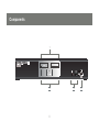
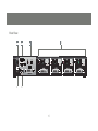
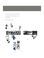
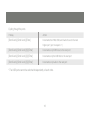
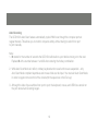
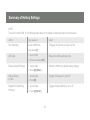
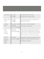
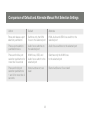
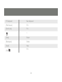
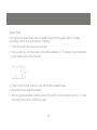
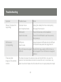
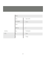
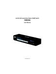
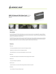
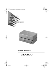
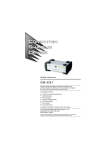
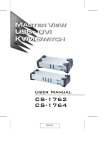
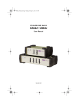
Installation Guide
USB 2.0 Dual Link DVI KVMP Switch
GCS1204
1
Part No. M1043
Table of Contents
Conventions
4
Firmware up-grade mode
26
Package Contents
5
The Firmware Upgrade Utility
32
Requirements
6
Troubleshooting
36
Operating systems
7
Specifications
37
Components
8
Video Specifications
39
Hardware Setup
12
14
Federal Communications Commission
(FCC) Statement
40
Basic Operation
Port ID numbering
17
CE Statement
42
Contact
43
Warranty
44
Advanced Configuration
21
Summary of Hotkey Settings
23
Comparison of Default and Alternate
Manual Port selection settings
25
3
Conventions
This manual uses the following conventions:
Monospaced Indicates text that you should key in.
[ ] Indicates keys you should press. For example, [Enter] means to press the Enter key. If keys need to
be chorded, they appear together in the same bracket with a plus sign between them: [Ctrl+Alt].
1. Numbered lists represent procedures with sequential steps.
• Bullet lists provide information, but do not involve sequential steps.
––> Indicates selecting the option (on a menu or dialog box, for example), that comes next.
For example, Start ––> Run means to open the Start menu, and then select Run.
Indicates critical information.
4
Package Contents
1- USB 2.0 DVI KVMP Switch
4- Custom KVM Cable Sets (6 ft)
1- USB-to-PS/2 Converter
1- Firmware Upgrade Cable
1- Power Adapter
1- User Manual
1- Registration form
Verify all the components are present and that nothing was damaged in shipping. If you encounter a problem,
contact your dealer, or IOGEAR.
Read this manual thoroughly and follow the installation and operation procedures carefully to prevent any damage
to the unit, and / or any of the devices connected to it.
5
Requirements
USB mouse
USB keyboard
Microphone and speakers (optional)
Monitor with a DVI input.
Computers
A DVI-D port
USB Type A port
Audio ports (optional)
6
Operating Systems
OS
Flavor
Windows
Linux
Unixa
Novell
Version
2000 and higher
RedHat
7.1 and higher; FedoraCore 2 and higher
SuSE
9.0 and higher
AIX
4.3 and higher
FreeBSD
4.2 and higher
Sun
Solaris 9 and higher
Netware
5.0 and higher
MAC
OS 9.0 and higher
Note: Supports Linux Kernel 2.6 and higher.
7
Components
1
2
8
3
4
No.
Component
Description
1
Port Select
Pushbuttons
Press a pushbutton for longer than two seconds to bring the KVM, USB, and audio
focus to the computer attached to its corresponding port.
2
Port LEDs
The Port LEDs are located below the Port selection buttons
The upper ones are the KVM port LEDs and the lower are the USB LEDs
KVM:
Lights Dim Orange to indicate the computer attached to the port is on line. It changes
to bright Orange when the port is selected and flashes to indicate auto scan has been
activated.
USB:
Lights dim green to indicate a USB connection. It changes to bright Green to indicate
to indicate the KVM is focused on the port
3
Console Ports
Audio
The connections for your main console microphone and speakers.
These audio ports have priority over the ports in the rear panel.
4
USB 2.0
Peripheral
Port
One of the two USB 2.0 peripheral ports. It is backwards compatible with USB-1
9
Rear View
1
2
5
6
4
3
10
No.
Component
Description
1
Firmware Upgrade Port
Connection for the firmware up-grade cable
2
USB Console Ports
USB1.0 Keyboard and mouse connections
3
Console Port Section
Monitor, mike, and speaker connections
4
CPU Port Section
Connections for the cables that link the switch to your computers.
Each CPU port is comprised of a microphone jack, speaker jack,
USB type B socket and a DVI connector
5
Power Jack
Power adapter connection
6
USB Peripheral Port
Connection for USB 2.0 peripherals ( printers, scanners, etc)
11
Hardware Setup
Make sure that power to all the devices you will be installing has been turned off. You must unplug
the power cords of any computers that have the Keyboard Power On function.
Cable Connection
To install your GCS1204, refer to the diagram on the following page. The numbers in the diagrams correspond to
the steps, below.
1. Connect your USB keyboard and mouse into the USB Console Ports located on the unit’s rear panel.
2. Connect your microphone, speakers, and monitor into the Console ports located on the unit’s rear panel
3. Using the KVM cables, connect the DVI connector to a DVI socket in the CPU Port section of the switch, then connect the accompanying USB, microphone and speaker connectors to their corresponding USB, microphone, and speaker sockets.
4. At the other end of the cable, connect the USB, video, microphone, and speaker cables to their respective ports on the computer.
5. Connect your USB peripherals to the type A sockets (one is located on the front, the other is located on the
rear of the unit).
6. Connect the power adapter that came with your switch to the jack on the switch then connect the adapter to
an AC power source.
12
7. Verify your connections: ports are correct and
icons match the connection type i.e. mouse
and mouse icon
8. Power on the computers.
5
1
2
3
6
5
2
1
5
2
3
4
13
6
2
5
Basic Operation
Manual Switching
There are two convenient methods to access the computers:
Manual – pressing the port selection pushbuttons located on the unit’s front panel.
Hotkey – entering key combinations from the keyboard. Hotkey port selection is discussed in the next chapter.
Manual port selection
Press and release a port selection pushbutton to focus the computer on the corresponding port. The USB
and Audio focus do not change (expect a 2 sec delay).
Press a port selection pushbutton twice to focus the audio on the corresponding port (expect a 2 sec
delay).
Press and hold a port selection pushbutton for more than 2 seconds to change KVM, USB, and Audio
focus to the computer on the selected port.
Press and hold port selection pushbuttons 1 and 2 for more than 2 seconds to start Auto Scan Mode.
14
Hotkey switching
All port switching begins by tapping the Scroll Lock key twice. The tables below describe the actions that
each combination performs.
Note:
If the Scroll Lock key conflicts with programs running on the computer, or your keyboard does not have a
Scroll Lock, see the section titled Advanced Switching to use the alternate switching method.
15
Cycling though the ports
Hotkey
Action
[Scroll Lock] [Scroll Lock] [Enter]
Increments the KVM, USB, and Audio focus to the next
higher port ( port 4 wraps to 1)
[Scroll Lock] [Scroll Lock] [K] [Enter]
Increments only KVM focus to the next port
[Scroll Lock] [Scroll Lock] [U] [Enter]
Increments only the USB hub to the next port
[Scroll Lock] [Scroll Lock] [S] [Enter]
Increments only Audio to the next port
* The USB ports cannot be switched independently of each other.
16
Port ID Numbering
Each CPU port on the GCS1204 is assigned a port number (1, 2, 3, or 4). The port numbers are marked
on the rear panel of the switch and each switch LED has a corresponding number for easy identification
The Port ID of a computer is derived from the CPU port number to which it is connected. For example, a
computer connected to CPU port 2 has a Port ID of 2.
The Port ID is used to specify which computer gets the KVM, USB peripheral, and / or audio focus with
the Hotkey port selection method
Going Directly to a Port
Note: The n stands for the computer’s Port ID number. Replace the n with the appropriate Port ID when
entering hotkey combinations
17
Hotkey
Action
[Scroll Lock] [Scroll Lock][n][Enter]
Brings the KVM, USB hub, and audio focus to the computer
attached to the specified port.
[Scroll Lock] [Scroll Lock][n] [K] Enter]
Brings only the KVM focus to the computer attached to the
specified port.
[Scroll Lock] [Scroll Lock] [n] [U] [Enter]
Brings only the USB hub focus to the computer attached to
the specified port.
[Scroll Lock] [Scroll Lock] [n] [S] [Enter]
Brings only the audio focus to the computer attached to the
specified port.
[Scroll Lock] [Scroll Lock] [n] [K] [U] [Enter]
Brings the KVM and USB hub focus to the computer
[Scroll Lock] [Scroll Lock] [n] [K] [S] [Enter]
Brings the KVM and audio focus to the computer
attached to the specified port
attached to the specified port.
[Scroll Lock] [Scroll Lock] [n] [U] [S] [Enter]
Brings the USB hub and audio focus to the computer
attached to the specified port.
18
Auto Scanning
The GCS1204’s Auto Scan feature automatically cycles KVM focus through the computer ports at regular intervals. This allows you to monitor computer activity without having to switch from port to port manually.
Note:
1. N stands for the number of seconds the GCS1204 will dwell on a port before moving on to the next.
Replace N with a number between 1 and 99 when entering the hotkey combination.
2. While Auto Scan Mode is in effect, ordinary keyboard and mouse functions are suspended – only Auto Scan Mode compliant keystrokes and mouse clicks can be input. You must exit Auto Scan Mode
in order to regain normal control of the console (hit the space bar or the Esc key).
3. Although the video focus switches from port to port, the keyboard, mouse, and USB focus remain on
the port where Auto Scanning began.
19
Hotkey
Action
[Scroll Lock] [Scroll Lock] [A] Enter]
Invokes Auto Scan. The KVM focus cycles from port to port at
5 second intervals (default interval)
[Scroll Lock] [Scroll Lock] [A] [N] Enter]
The KVM focus cycles from port to port at N seconds interval
20
Advanced Configuration
Advanced Switching
Hotkey Setting Mode
In some instances the default hotkey settings conflict with programs running on your computer, and in
some instances the default hotkeys either do not exist on your keyboard (MAC keyboards for instance do
not have a Scroll Lock key), or are inconvenient to use, so The Hotkey Setting Mode allows you to select
alternate configurations for the KVM’s hotkeys.
When HSM is active, the Caps Lock, and Scroll Lock LEDs flash in succession to indicate that HSM is in
effect. They stop flashing and revert to normal status when you exit HSM.
Ordinary keyboard and mouse functions are suspended – only Hotkey compliant keystrokes (described in
the sections that follow), can be input.
At the conclusion of some hotkey operations, you automatically exit hotkey mode. With some operations,
you must exit manually. To exit HSM manually, press the Esc key, or the Spacebar.
21
Invoking Hotkey Setting Mode (Default)
1. Press and hold down [Num Lock] (the Clear key on MAC keyboards).
2. Press and release [-].
3. Release [Num Lock] (the Clear key on MAC keyboards).
To Toggle to the alternate Hotkey Setting Mode (HSM):
1. Press and hold down [Num Lock] (the Clear key on MAC keyboards)
2. Press and release [-].
3. Release [Num Lock] (the Clear key on MAC keyboards)
4. Press and release [H].
Invoking Hotkey Setting Mode (Alternate)
1. Press and hold down [Ctrl].
2. Press and release [F12].
3. Release [Ctrl].
22
Summary of Hotkey Settings
NOTE:
The term “invoke HSM” in the following table refers to the default or alternate method chosen above
Action
Key sequence
result
Port Switching
Invoke HSM Press
Changes the [Scroll Lock] key to [Ctrl]
and release [T]
USB reset
Resets the USB peripheral ports
1. Invoke HSM.
2. Press and release [F5]
Restore Default Settings
Reset the KVM to its default hotkey settings
1. Invoke HSM.
2. Press [R] [Enter].
Hotkey Beeper
Control
1. Invoke HSM.
Disable Port Switching
Hot Keys
1. Invoke HSM
Toggles the Beeper On and Off
2. Press [B]
Toggles Hotkey Switching on or off
2. Press [X] [Enter]
23
Other OS Mode
1. Invoke HSM
2. Press [F1].
Reset keyboards and mice under some
special OS’s that do not support USB 2.0
Mouse Emulation
Control
1. Invoke HSM
2. Press [M].
Allows the special programming of multifunction mice to
operate through the KVM
List Hotkey
Settings
1. Open a word processor
2. Invoke HSM.
3. Press and release [F4].
Prints a list of the current hotkey settings in
your text editor or word processor
Display
Emulation
Technology
1. Invoke HSM
2. Press and release [D]
Display Emulation Technology eliminates the problems of
your display reverting to default resolution when switching
between computers, or displaying a default resolution if the
KVM is not focused on the computer while it is booting.
Alternative
Manual Port
Selection
Settings
1. Invoke HSM
2. Press and release [S]
Toggles between the default and the alternative front panel
pushbutton port selection settings See the table on the
following page for comparisons
24
Comparison of Default and Alternate Manual Port Selection Settings
Action
Default
Alternate
Press and release a port
selection pushbutton
Switches only the KVM
focus to the selected port
KVM, Audio and USB focus switch to the
selected port
Press a port selection
pushbutton twice
Audio focus switches to
the selected port
Audio focus switches to the selected port
Press and hold a port
selection pushbutton for
more than 2 seconds
KVM focus, USB, and
Audio focus switch to the
selected port
Switches only the KVM focus
to the selected port
Press and hold port
selection pushbuttons
1 and 2 for more than 2
seconds
Starts AutoScan at 5 sec
dwell
Starts AutoScan at 5 sec dwell
25
The Firmware Upgrade Mode
Firmware Upgrade Mode
To set the KVM to Firmware Upgrade Mode:
1. Invoke your HSM.
2. Key in: upgrade
3. Press [Enter].
The front panel LEDs flash to indicate Firmware Upgrade Mode is in effect. To exit Firmware Upgrade
Mode, you must power off the switch. See The Firmware Upgrade Utility for details
Keyboard Operating Platform
The KVM’s default port configuration is for a PC compatible keyboard. If you are using a PC compatible
keyboard and you have a Mac or Sun attached to a port, you can change the port’s keyboard operating
platform configuration to emulate a Mac or Sun keyboard.
26
1. Bring the KVM focus to the port you want to set.
2. Invoke HSM.
3. Press and release the appropriate Function key (see table below).
Function Key
Operation
[F2]
Enables Mac keyboard emulation, see Mac Keyboard Emulation,
[F3]
Enables Sun keyboard emulation, see Sun Keyboard Emulation
[F10]
Disables keyboard emulation. Key presses are passed straight through. When your console
uses a Mac keyboard to access a Mac attached to a port, for example
After completing this procedure, you automatically exit HSM.
The PC compatible (101/104 key) keyboard can emulate the functions of Mac and Sun keyboards when
the Control key [Ctrl] is used in conjunction with other keys. The emulation mappings are listed in the table
on the next page.
27
PC Keyboard
Mac Keyboard
[Shift]
Shift
[Ctrl]
Ctrl
[Ctrl] [1]
[Ctrl] [2]
[Ctrl] [3]
[Ctrl] [4]
[Alt]
Alt
28
PC Keyboard
Mac Keyboard
[Print Screen]
F13
[Scroll Lock]
F14
=
[Enter]
Return
[Backspace]
Delete
[Insert]
Help
[Ctrl]
F15
29
PC Keyboard
Sun Keyboard
[Ctrl] [T]
Stop
[Ctrl] [F2]
Again
[Ctrl] [F3]
Props
[Ctrl] [F4]
Undo
[Ctrl] [F5]
Front
[Ctrl] [F6]
Copy
[Ctrl] [F7]
Open
[Ctrl] [F8]
Paste
[Ctrl] [F9]
Find
30
PC Keyboard
Sun Keyboard
[Ctrl] [F10]
Cut
[Ctrl] [1]
[Ctrl] [2]
[Ctrl] [3]
[Ctrl] [4]
[Ctrl] [H]
Help
Compose
Note: Press and release the first key [Ctrl], then press and release the activation key.
31
The Firmware Upgrade Utility
The Windows-based Firmware Upgrade Utility (FWUpgrade.exe) provides a smooth, automated process
for upgrading the KVM switch’s firmware.
The Utility comes as part of a Firmware Upgrade Package that is specific for each device. New firmware
upgrade packages are posted on our Website as new firmware revisions become available. Check the
web site regularly to find the latest packages and information relating to them.
Before you Begin
To prepare for the firmware upgrade, do the following:
1. From a computer that is not part of your KVM installation ( disconnect the computer from the KVM) go to our Internet support site and choose the model name that relates to your device (GCS1204) to
get Firmware Upgrade Packages.
2. Choose the Firmware Upgrade Package you want to install (usually the most recent), and download it
to your computer.
3. Use the Firmware Upgrade Cable provided with this unit, to connect a COM port on your computer to the Firmware Upgrade Port of your switch.
32
4. Shut down the computers on your GCS1204 installation.
5. Invoke Firmware Upgrade Mode. The front panel LEDs flash together to indicate Firmware Upgrade
Mode is in effect.
Starting the Upgrade
To upgrade your firmware:
1. Run the downloaded Firmware Upgrade Package file – either by double clicking the file icon, or by opening a command line and entering the full path to it.
The Firmware Upgrade Utility Welcome screen appears.
2. Read the License Agreement (enable the I Agree radio button).
3. Click Next to continue. The Firmware Upgrade Utility main screen appears.
The Utility inspects your installation. All the devices capable of being upgraded by the package are listed in
the Device List panel.
33
4. As you select a device in the list, its description appears in the Device Description panel.
5. After you have made your device selection(s), Click Next to perform the upgrade.
If you enabled Check Firmware Version, the Utility compares the device’s firmware level with that of the
upgrade files. If it finds that the device’s version is higher than the upgrade version, it brings up a dialog
box informing you of the situation and gives you the option to Continue or Cancel.
If you did not enable Check Firmware Version, the Utility installs the upgrade files without checking
whether they are a higher level, or not. As the Upgrade proceeds, status messages appear in the Status
Messages panel, and the progress toward completion is shown on the Progress bar.
After the upgrade has completed, a screen appears to inform you that the procedure was successful.
Click Finish to close the Firmware Upgrade Utility.
After a successful completion, the switches exit Firmware Upgrade Mode, and reset themselves.
34
Upgrade Failed
If the Upgrade Succeeded screen does not appear, it means that the upgrade failed to complete
successfully, in which case you should do the following:
1. Power off the GCS1204 and remove its housing.
2. Using a jumper cap, short the jumper on the mainboard labeled J17. The diagram below indicates the jumper location on the GCS1204 board:
3. Power on the GCS1204. It will now work with the factory default firmware.
4. Repeat the firmware upgrade procedure.
5. After the upgrade procedure completes, power off the switch, remove the jumper cap from J17, close the housing, and power the GCS1204 on again.
35
Troubleshooting
Symptom
Possible Cause
Action
Mouse / Keyboard not
responding.
Improper mouse
Unplug the cable(s) from the console port(s),
and/or keyboard reset.
then plug it/them back in.
KVM switch
Power off all devices on the installation.
needs to be reset.
Power off the KVM switch; wait five seconds;
then power up
USB devices
USB ports
not responding.
need to reset.
Unplug the device’s USB cable from the USB port
on the switch’s rear panel, then plug it back in.
PC or OS does not support
USB 2.0.
There are ghost
images on the external
monitor.
The GCS1204 has a built-in USB 2.0 hub, so
will not support PCs or OS that do not support
USB 2.0.
The distance between the external console and the GCS1204 is too great. The
maximum VGA cable distance should not exceed 20m and, in some cases, may
need to be shorter. Replace the VGA cable with one of an appropriately short length.
36
Specifications
Function
GCS1782(GCS1784)
Computer Connections
4
CPU Port Selection
Front Panel Pushbuttons; Hotkey
Console Connectors
Keyboard
1 x USB Type A F (black, rear panel)
Mouse
1 x USB Type A F (black, rear panel)
Video
1 x DVI-I F (white)
Audio*
Line in Port
2x Mini Stereo Jack
(green; 1 x front panel, 1 x rear panel)
Microphone Port 2x Mini Stereo Jack
(pink; 1 x front panel, 1 x rear panel)
Power Consumption
DC 5.3V, 4.8W
Computer Connectors
KB /
USB X 2
37
Mouse
Video
Dual Link DVI
F/W Upgrade
3.5mm
Power
1
USB Hub
2
Switches
4 ea
Port Selection
LEDs
4
Green
4
Orange
38
Video Specifications
DVI-D:
2560 x 1600 @ 60Hz (Dual Link);
supports Apple 20”, 23”, 30” Cinema Display;
supports Viewsonic 22” LCD monitor
DVI-A:
2048 x 1536; DDC2B
Supports Special monitors to 3840 x 2400 @
13Hz (Single Link);
39
Federal Communications Commission (FCC) Statement
15.21
You are cautioned that changes or modifications not expressly approved by the part responsible for
compliance could void the user’s authority to operate the equipment.
15.105(b)
This equipment has been tested and found to comply with the limits for a Class B digital device, pursuant
to part 15 of the FCC rules. These limits are designed to provide reasonable protection against harmful
interference in a residential installation. This equipment generates, uses and can radiate radio frequency
energy and, if not installed and used in accordance with the instructions, may cause harmful interference
to radio communications. However, there is no guarantee that interference will not occur in a particular
installation. If this equipment does cause harmful interference to radio or television reception, which
can be determined by turning the equipment off and on, the user is encouraged to try to correct the
interference by one or more of the following measures:
-Reorient or relocate the receiving antenna.
-Increase the separation between the equipment and receiver.
-Connect the equipment into an outlet on a circuit different from that to which the receiver is connected.
-Consult the dealer or an experienced radio/TV technician for help.
40
Operation is subject to the following two conditions:
1) this device may not cause interference and
2) this device must accept any interference, including interference that may cause undesired operation of
the device.
FCC RF Radiation Exposure Statement:
This equipment complies with FCC radiation exposure limits set forth for an uncontrolled environment.
End users must follow the specific operating instructions for satisfying RF exposure compliance. This
transmitter must not be co-located or operating in conjunction with any other antenna or transmitter.
41
CE Statement
This device has been tested and found to comply with the requirements set up in the council directive
on the approximation of the law of member states relating to EMC Directive 89/336/EEC, Low Voltage
Directive 73/23/EEC and R&TTE Directive 99/5/EC.
42
Contact
IOGEAR, INC.
23 Hubble
Irvine, CA 92618
P 949.453.8782
F 949.453.8785
Visit us at: www.iogear.com
© 2008 IOGEAR. All Rights reserved. Part No. M1043
IOGEAR, the IOGEAR logo, are trademarks or registered trademarks of IOGEAR, Inc. Microsoft and
Windows are registered trademarks of Microsoft Corporation. All other brand and product names
are trademarks or registered trademarks of their respective holders. IOGEAR makes no warranty of
any kind with regards to the information presented in this document. All information furnished here is
for informational purposes only and is subject to change without notice. IOGEAR, Inc. assumes no
responsibility for any inaccuracies or errors that may appear in this document.
43
Warranty
WE’RE HERE TO HELP YOU!
NEED ASSISTANCE SETTING UP THIS PRODUCT?
Make sure you:
1. Use the live chat at www.iogear.com to try and solve any issues you may be having with the product
2. Visit the Tech Info Library/FAQ on www.iogear.com (under the Support tab)
3. Call the 24/7 tech support line at 1(866) 946-4327 (U.S. only) or (949) 453-8782
Warranty Information
This product carries a 3 Year Limited Warranty. For the terms and conditions of this warranty, please go
to http://www.iogear.com/support/warranty or call 1-866-946-4327
Register online at http://www.iogear.com/register
Important Product Information
Product Model _________________
Serial # _______________________
44
About Us
FUN
IOGEAR offers connectivity solutions that are innovative, fun, and stylish,
helping people enjoy daily life using our high technology products.
GREEN
IOGEAR is an environmentally conscious company that emphasizes the
importance of conserving natural resources. The use of our technology
solutions helps reduce electronic waste.
HEALTH
IOGEAR supports healthy and fit lifestyles. By integrating products with the
latest scientific developments, IOGEAR’s solutions enhance the life of endusers.
© 2007 IOGEAR, INC.