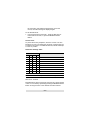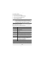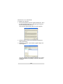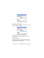
1
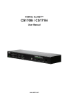
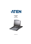
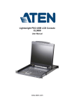
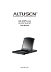
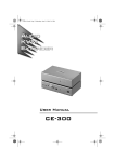
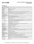
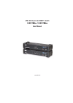
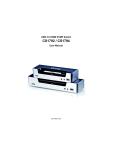
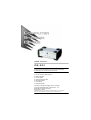
User Manual CS-231 Read this guide thoroughly and follow the installation and operation procedures carefully in order to prevent any damage to the units and/or any devices that connect to them. This package contains: 1 CS-231 Computer Sharing Device 1 USB KVM Cable 1 Power Adapter 1 Firmware Upgrade Cable 1 DIP Switch Sticker 1 User Manual 1 Quick Start Guide If anything is damaged or missing, contact your dealer. © Copyright 2005-2006 ATEN® International Co., Ltd. Manual Part No. PAPE-1290-100G Printing Date: 11/2006 ATEN and the ATEN logo are trademarks of ATEN International Co., Ltd. All rights reserved. All other trademarks are the property of their respective owners. Note: This equipment has been tested and found to comply with the limits for a Class B digital device, pursuant to Part 15 of the FCC Rules. These limits are designed to provide reasonable protection against harmful interference in a residential installation. This equipment generates, uses and can radiate radio frequency energy, and if not installed and used in accordance with the instruction manual, may cause interference to radio communications. However, there is no guarantee that interference will not occur in a particular installation. If this equipment does cause harmful interference to radio or television reception, which can be determined by turning the equipment off and on, the user is encouraged to try to correct the interference by one or more of the following measures: Reorient or relocate the receiving antenna; Increase the separation between the equipment and receiver; Connect the equipment into an outlet on a circuit different from that which the receiver is connected; Consult the dealer or an experienced radio/television technician for help. This product is RoHS compliant. Overview The CS-231 is a powerful, micro-processor controlled computer sharing device. It is a multi-user, single-tasking device that enables two users to share the use of a single USB or PS/2 computer from two separate consoles (USB keyboard, USB mouse, and monitor). The CS-231 is ideal for small office and home office (SOHO) environments. All programs, files and resources on the computer can be easily accessed and shared by both users without the bother and expense of setting up a costly network environment. Features Single computer shared by two USB consoles Supports USB and PS/2 computers Multiplatform support (Windows, Mac, Unix, and Linux) Manual or Auto console selection Control the system with Hotkeys Firmware upgradable Private Mode for a privileged user Screen Saver function Choose from four Timeout settings Supports VGA, SVGA, and MultiSync monitors No software required -3- System Requirements Operating System Microsoft® Windows® 98SE, ME, 2000, XP, 2003 or later Red Hat Linux 7.1, 7.2, 7.3, 8.0 or later Mandriva Linux 9.0 or later SUSE 8.2 or later FreeBSD 4.2, 4.3, 4.5 or later Netware 6.0 or later Netware 5.0 (PS/2 computers only) Mac OS 8.6, 9.0, 9.1, X, 10.1, 10.2, 10.3, 10.4 or later Cables Use ATEN's high-quality, custom cables to ensure reliable switching among consoles. To purchase ATEN’s custom cables contact your dealer. Description Part Number PS/2 KVM Cables 2L-5202P (1.8 m) 2L-5203P (3 m) 2L-5206P (6 m) USB KVM Cables 2L-5201U (1.2 m) 2L-5202U (1.8 m) 2L-5203U (3 m) 2L-5205U (5 m) -4- CS-231 Front View 1 2 No. 3 4 Component Description 1 MANUAL/AUTO This button is used to switch between Manual and Selection Auto Modes. The default is Auto Mode. Repeatedly Button pressing the button cycles through the modes in the following order: Auto Mode -> Console 1 (Manual) -> Console 2 (Manual) -> Auto Mode. 2 C1 LED* Lights when Console 1 accesses the computer. Turns off when Console 2 accesses the computer. 3 C2 LED* Lights when Console 2 accesses the computer. Turns off when Console 1 accesses the computer. 4 MANUAL LED Lights to indicate that the CS-231 is set to Manual Mode. In Auto Mode the LED does not illuminate. * In Auto Mode, when neither console is accessing the computer, both Console LEDs are illuminated. -5- CS-231 Rear View 1 6 No. 2 3 4 5 7 Component Description 1 Firmware Upgrade Port The firmware upgrade cable connects here and to the administrator's computer to upgrade the firmware (see Firmware Upgrade, page 15). 2 DIP Switch This is a 4-pin DIP switch. Use it to set the Timeout, Private Mode, and Screen Saver functions (see DIP Switch Settings Table, page 11). 3 Reset Button Press this semi-recessed button to reset the system. 4 Console 2 Ports The cables from the VGA monitor and USB keyboard and mouse of Console 2 plug in here. 5 Console 1 Ports The cables from the VGA monitor and USB keyboard and mouse of Console 1 plug in here. 6 Power Jack The power adapter cable plugs in here. 7 PC Port* The 15-pin SPHD connector on the provided KVM cable plugs in here. At the other end of the cable, the HDB-15 and USB connector plug into the corresponding ports on the computer. If the computer does not have an available USB port, a KVM cable with PS/2 keyboard and mouse connectors may be purchased separately. * The shape and pin assignment of this 15-pin SPHD connector has been specifically modified so that only KVM cables designed to work with this switch may be used. Do NOT attempt to use a cable with ordinary 15-pin VGA connectors to link this port to the computer. -6- Installation 1. Make sure that power to all the devices you will be connecting up has been turned off. You must unplug the power cords of any computers that have the Keyboard Power On function. 2. To prevent damage to your equipment, make sure that all devices you will be connecting up are properly grounded. Installing your new CS-231 involves the following seven steps (refer to the diagram on the following page): 1. Connect the 15-pin SPHD connector on the KVM cable to the PC port on the CS-231. 2. Connect the VGA video connector on the KVM cable to the VGA video output port on the computer. Plug the USB connector into any available USB port. 3. Plug the keyboard, mouse and monitor for the console that you want to designate as Console 1 into the Console 1 ports. 4. Plug the keyboard, mouse and monitor for the console that you want to designate as Console 2 into the Console 2 ports. 5. Set the DIP switch (see DIP Switch Settings Table, page 11, for details). 6. Plug the power adapter into an AC power source; plug the power adapter cable into the power jack on the CS-231. 7. Power on the computer and monitors. -7- Installation Diagram: 4 5 6 1 2 3 -8- Operation There are two operation modes: Auto Mode and Manual Mode. Auto Mode Auto Mode operates according to the following rules: 1. When the CS-231 is turned on it starts in Auto Mode, and operates on a first-come-first-served basis. Both Console LEDs are On; the Manual LED is Off. 2. The first user to strike the keyboard or move the mouse gains control of the computer. As soon as this occurs: The Console LED that corresponds to the user's console turns On. The Console LED for the other console turns Off. The CS-231 locks onto that user's console. A message appears on the other user’s monitor indicating that the system is in use. After 10 seconds, the message disappears and the user can view the computer display. If the user strikes the keyboard or moves the mouse, the OSD message is displayed again. The user who has control of the computer can prevent the other user from viewing the computer display by entering the following Hotkey combination: [Num Lock]+[-],[D] If the other user strikes the keyboard or moves the mouse, a message appears indicating that the system is in use. After 10 seconds, the message disappears and the monitor displays a black background. If the user strikes the keyboard or moves the mouse, the OSD message is displayed again. 3. If the user who has access does not strike the keyboard or move the mouse before the Timeout Period (set with DIP switch pins 1 and 2) elapses: The CS-231 unlocks from that user's console; Then, the CS-231 switches to Auto Mode; -9- Both Console LEDs turn On; The Manual LED is Off (since the CS-231 is in Auto Mode); Either console may take control of the computer. 4. To terminate Auto Mode access, repeatedly press the MANUAL/AUTO Button until the desired console controls the device. Timeout In Auto Mode, the setting of DIP switch pins 1 and 2 determines the amount of time that passes from the last input by the controlling console to when the console lock is released. Refer to the DIP Switch Settings Table, page 11, for the pin settings and their corresponding Timeout lengths. (See page 9 for more information about Auto Mode.) Note: For best results, set the DIP switch pins BEFORE turning on either the CS-231 or the computer. Private Mode (Console 1) Private Mode operates within Auto Mode. In Private Mode, the Console 1 user can control the computer, while preventing the Console 2 user from viewing and controlling the computer. The Timeout Period does not apply in Private Mode. To enter Private Mode: 1. Make sure that the device is in Auto Mode and that DIP switch pin 3 is set to the On position. 2. Wait for the Timeout period to expire. 3. From the keyboard of Console 1, press the Shift key six times within two seconds. After the Timeout Period expires, Console 1 will display the computer desktop and have control of the computer. A message appears on the monitor of Console 2 indicating that the system is in use. After 10 seconds, the message disappears and the monitor displays a black background. If - 10 - the Console 2 user strikes the keyboard or moves the mouse, the OSD message is displayed again. To exit Private Mode: 1. From the keyboard of Console 1, press the Shift key six times within 2 seconds; or, press the MANUAL/AUTO Button. Screen Saver To protect the screen phosphors, when the CS-231 is in Auto Mode and no one is accessing the computer, a stripe image can scroll down the screen. To enable this function, set DIP switch pin 4 to the On position. DIP Switch Settings Table DIP Switch Pins Function 1 2 3 4 On On X X 5 Second Timeout Off On X X 60 Second Timeout On Off X X 125 Second Timeout Off Off X X 255 Second Timeout X X On X Private Mode Enabled X X Off X Private Mode Disabled X X X On Screen Saver Enabled X X X Off Screen Saver Disabled Note: Press a DIP switch pin down to turn it on, up to turn it off. Manual Mode Manual Mode is used to access the computer for a longer period of time. It is invoked by repeatedly pressing the MANUAL/AUTO Button to bring the focus to the desired console as follows: - 11 - Auto Mode > Console 1 > Console 2 > Auto Mode When Manual Mode is invoked, the CS-231 switches to the selected console and prohibits the other console from controlling the computer. The selected console retains control until the MANUAL/AUTO Button is pressed again. A message appears on the other user’s monitor indicating that the system is in use. After 10 seconds, the message disappears and the user can view the computer display. If the user strikes the keyboard or moves the mouse, the OSD message is displayed again. The user who has control of the computer can prevent the other user from viewing the computer display by entering the following Hotkey combination: [Num Lock]+[-],[D] If the other user strikes the keyboard or moves the mouse, a message appears indicating that the system is in use. After 10 seconds, the message disappears and the monitor displays a black background. If the user strikes the keyboard or moves the mouse, the OSD message is displayed again. To switch to the other console, repeatedly press the Manual/Auto Mode Button until the desired console controls the device, or enter the following hotkey combination: [Scroll Lock], [Scroll Lock], [Enter] Note: If using the Scroll Lock key conflicts with other programs running on the computer, the Ctrl key can be used instead. See HSM Summary Table, page 13, for details. Hotkey Setting Mode Hotkey Setting Mode is used to configure your CS-231 switch. All operations begin with invoking Hotkey Setting Mode (HSM). - 12 - Invoking HSM To invoke HSM do the following: 1. Press and hold down the Num Lock key. 2. Press and release the minus [-] key. 3. Release the Num Lock key. Note: 1. The minus key must be released within one-half second, otherwise Hotkey invocation is canceled. 2. There is an alternate key combination to invoke HSM. See HSM Summary Table, page 13, for details. HSM Summary Table After invoking HSM (see page 12), key in one of the following keys to perform the corresponding function: Key Function [F1] Sets the PC keyboard layout. [F2] Sets the Apple keyboard layout. (Set this before turning on the Mac computer.) [F4] Lists the current hotkey settings via the Paste function of a text editor. [F5] Performs a USB reset. [D] Turn the other console's monitor off or on. (This setting applies until changed or until the device is powered off.) [H] Toggles between the default and alternate HSM invocation keys. The alternate HSM invocation keys are [Ctrl] + [F12]. [R], [Enter] [T] Restores the default Hotkey settings. Toggles between the default and alternate console switching keys. The default console switching keys are [Scroll Lock] [Scroll Lock] [Enter]. The alternate console switching keys are [Ctrl] [Ctrl] [Enter]. [upgrade], [Enter]* Invokes Firmware Upgrade Mode. * Key in the letters u-p-g-r-a-d-e, and then press [Enter]. - 13 - Keyboard Emulation Mapping Apple Keyboard The PC compatible (101/104 key) keyboard can emulate the functions of the Apple keyboard. The corresponding functions are shown in the table below. Note: When using hotkey combinations, press and release the first key, then press and release the second one. PC Keyboard Mac Keyboard [Shift] Shift [Ctrl] Ctrl [Ctrl], [1] [Ctrl], [2] [Ctrl], [3] [Ctrl], [4] [Alt] Alt [Print Screen] F13 [Scroll Lock] F14 = [Enter] Return [Backspace] Delete [Insert] Help F15 [Ctrl], - 14 - Firmware Upgrade The Windows-based Firmware Upgrade Utility (FWUpgrade.exe) provides a smooth, automated process for upgrading the computer sharing device’s firmware. The Utility comes as part of a Firmware Upgrade Package that is specific for each device. New firmware upgrade packages are posted on our Website as new firmware revisions become available. Check our Website regularly to find the latest packages and information relating to them. Before You Begin To prepare for the firmware upgrade, do the following: 1. From a computer that is not part of your installation, go to our Website and choose the model name that relates to your device (CS-231) to get a list of available Firmware Upgrade Packages. 2. Choose the Firmware Upgrade Package you want to install (usually the most recent) and download it to your computer. 3. Shut down the computer(s) on your CS-231 installation. 4. Connect the provided firmware upgrade cable to the firmware upgrade port on the CS-231 and to a COM port on the computer you used to download the Firmware Upgrade Package. 5. From the console connected to the CS-231, invoke HSM (see page 12). Key in the letters u-p-g-r-a-d-e, and then press [Enter]. When in firmware upgrade mode the front panel LEDs flash in unison. - 15 - Starting the Upgrade To upgrade your firmware: 1. Run the downloaded Firmware Upgrade Package file - either by double clicking the file icon, or by opening a command line and entering the full path to it. The Firmware Upgrade Utility Welcome screen appears: 2. Read and Agree to the License Agreement (enable the I Agree radio button). 3. Click Next to continue. The Firmware Upgrade Utility main screen appears: The Utility inspects your installation. All the devices capable of being upgraded by the package are listed in the Device List panel. - 16 - 4. As you select a device in the list, its description appears in the Device Description panel. 5. After you have made your device selection(s), Click Next to perform the upgrade. If you enabled Check Firmware Version, the Utility compares the device's firmware level with that of the upgrade files. If it finds that the device's version is higher than the upgrade version, it brings up a dialog box informing you of the situation and gives you the option to Continue or Cancel. If you did not enable Check Firmware Version, the Utility installs the upgrade files without checking whether or not they are a higher level. As the Upgrade proceeds, status messages appear in the Status Messages panel, and the progress toward completion is shown on the Progress bar. - 17 - Upgrade Succeeded After the upgrade has completed, a screen appears to inform you that the procedure was successful: Click Finish to close the Firmware Upgrade Utility. After a successful completion, the switches exit Firmware Upgrade Mode. Upgrade Failed If the Upgrade Succeeded screen does not appear, then the upgrade failed to complete successfully. You should repeat the upgrade procedure from the beginning. - 18 - Specifications Function CS-231 Computer Connections 1 Console Connections 2 Console Selection Connectors Switches LEDs Console Port Hotkey, Pushbutton Keyboard 2 x USB Type A Female (White) Video 2 x HDB-15 Female (Blue) Mouse 2 x USB Type A Female (White) Computer Port 1 x SPHD-15 Female (Green) F/W Upgrade 1 x RJ-11 Female (Black) Power 1 x DC Jack (Black) Mode Selection 1 x Pushbutton Reset 1 x Semi-recessed Pushbutton DIP 1 x 4-pin Mode 1 (Orange) Selected 2 (Green) Video 1920x1440@60Hz; DDC2B Timeout Settings 5, 60, 125, 255 Seconds Power Consumption DC 5.3V, 2.2W (max.) Environment 0–50° C Physical Properties Operating Temp. Storage Temp. -20–60° C Humidity 0–80% RH, Non-condensing Housing Metal Weight 0.56 kg Dimensions (L x W x H) 14.3 x 8.7 x 5.5 cm - 19 - Troubleshooting Problem Solution Nothing happens when I move the mouse or press keys on the keyboard. 1. Ensure that the KVM cable connectors are firmly secured to the computer port on the CS-231 and to the keyboard and mouse ports on the computer before connecting the power cable or turning on the computer. 2. Press the Manual/Auto Mode Button to switch the console. I am using two monitors with differing screen resolutions. Why can’t I see the entire desktop on the monitor with the higher resolution? The monitor with the lowest screen resolution sets the maximum screen resolution that can be used. Choose a screen resolution in the computer’s graphics card that is supported by both monitors. After setting a PC keyboard to emulate the Apple keyboard layout, it still is not emulating the Mac keyboard. Restart the computer. Limited Warranty IN NO EVENT SHALL THE DIRECT VENDOR'S LIABILITY EXCEED THE PRICE PAID FOR THE PRODUCT FROM DIRECT, INDIRECT, SPECIAL, INCIDENTAL, OR CONSEQUENTIAL DAMAGES RESULTING FROM THE USE OF THE PRODUCT, DISK, OR ITS DOCUMENTATION. The direct vendor makes no warranty or representation, expressed, implied, or statutory with respect to the contents or use of this documentation, and especially disclaims its quality, performance, merchantability, or fitness for any particular purpose. The direct vendor also reserves the right to revise or update the device or documentation without obligation to notify any individual or entity of such revisions, or update. For further inquiries, please contact your direct vendor. - 20 -