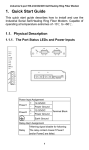
1
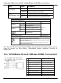
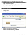
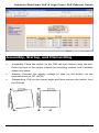
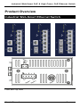
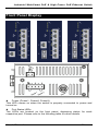
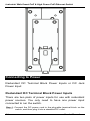
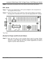
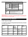
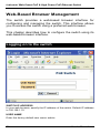
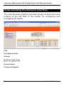
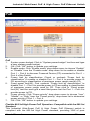
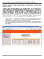
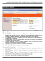
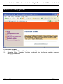
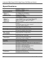
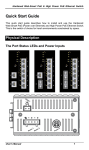
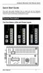
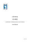
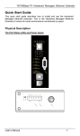
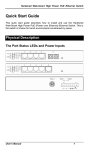
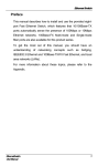
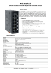
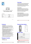
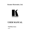
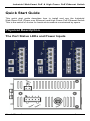
Industrial Web-Smart PoE & High Power PoE Ethernet Switch
Quick Start Guide
This quick start guide describes how to install and use the Industrial
Web-Smart PoE (Power over Ethernet) and High Power PoE Ethernet Switch.
This is the switch of choice for harsh environments constrained by space.
Physical Description
The Port Status LEDs and Power Inputs
User’s Manual
1
Industrial Web-Smart PoE & High Power PoE Ethernet Switch
LED
Link/ACT
PoE
High Power PoE
State
Indication
Steady
A valid network connection established.
Flashing
Transmitting or receiving data.
ACT stands for ACTIVITY.
Steady
Power Device (PD) is connected.
Off
Power Device (PD) is disconnected.
Power Input Assignment
Power3
Power2
Power1
48, 55VDC (High Power)
+
48, 55VDC (High Power)
-
Power Ground
+
48, 55VDC (High Power)
-
Power Ground
DC Jack
Terminal
Block
Earth Ground
Relay Output Rating
0.1A @ 24VDC
Relay Alarm Assignment
FAULT
*Warning signal disable for following:
The relay contact closes if Power1 and Power2 are both
failed but Power3 on.
The relay contact closes if Power3 is failed but Power1
and Power2 are both on.
DC Terminal Block Power Inputs: There are two pairs of power inputs can be
used to power up this switch. Redundant power supplies function is
supported.
The 10/100Base-TX and 100Base-FX/BX Connectors
The 10/100Base-TX Connections
The following lists the pinouts of
10/100Base-TX ports.
2
Pin Regular Ports
Uplink port
1
Output Transmit Data + Input Receive Data +
2
Output Transmit Data - Input Receive Data -
3
Input Receive Data +
Output Transmit Data +
4
NC
NC
5
NC
NC
6
Input Receive Data -
Output Transmit Data -
7
NC
NC
8
NC
NC
User’s Manual
Industrial Web-Smart PoE & High Power PoE Ethernet Switch
The 100Base-FX Connections
The fiber port pinouts
The Tx (transmit) port of device I is connected to the Rx (receive) port of device II,
and the Rx (receive) port of device I to the Tx (transmit) port of device II.
The WDM 100Base-BX Connections
The fiber port pinouts
Only one single-mode optical fiber is required to transmit and receive data.
Functional Description
z
Meets EN61000-6-2 & EN61000-6-3 EMC Generic Standard Immunity
z
Manageable via Web browser interface.
z
Supports IEEE802.3af Power over Ethernet (PoE) Power Sourcing
z
High Power PoE design up to 30W (enhancement of IEEE802.3af
z
Supports
for industrial environment.
Equipment (PSE).
PoE).
IEEE802.3/802.3u/802.3x.
Auto-negotiation:
10/100Mbps-full/half-duplex; Auto MDI/MDIX.
z
100Base-FX: Multi mode SC or ST type, Single mode SC or ST type.
100Base-BX: WDM Single mode SC type.
z Supports 1024 MAC addresses. Provides 1M bits memory buffer.
z
Store-and-forward mechanism.
z
Full wire-speed forwarding rate.
Alarms for power and port link failure by relay output.
PoE: Redundant 48VDC Terminal Block power inputs and 48VDC DC
JACK power input for 15.4W per PoE port. Operating voltage and Max.
current consumption: 1.5A @ 48VDC. Power consumption: 72W Max.
z High Power PoE: Redundant 55VDC Terminal Block power inputs and
55VDC DC JACK power input for 30W per High Power PoE port.
User’s Manual
3
z
z
Industrial Web-Smart PoE & High Power PoE Ethernet Switch
z
Operating voltage and Max. current consumption: 2.3A @ 55VDC.
Power consumption: 130W Max.
-10℃ to 60℃ (14℉ to 140℉) operating temperature range. Tested for
z
Supports DIN-Rail, Panel, or Rack Mounting installation.
functional operation @ -20℃ to 70℃ (-4℉ to 158℉).
Web Configuration
z
Login the switch:
Specify the default IP address (192.168.1.10) of the switch in the web
browser. A login window will be shown as below:
z
Enter the factory default user name: admin.
Enter the factory default password (no password).
Then click on the “OK” button to log on to the switch.
4
User’s Manual
Industrial Web-Smart PoE & High Power PoE Ethernet Switch
Assembly, Startup, and Dismantling
•
Assembly: Place the switch on the DIN rail from above using the slot.
Push the front of the switch toward the mounting surface until it audibly
snaps into place.
•
Startup: Connect the supply voltage to start up the switch via the
terminal block (or DC JACK).
•
Dismantling: Pull out the lower edge and then remove the switch from
the DIN rail.
User’s Manual
5
Industrial Web-Smart PoE & High Power PoE Ethernet Switch
Preface
This manual describes how to install and use the Industrial
Web-Smart PoE & High Power PoE Ethernet Switch. This
switch introduced here is designed to deliver full scalability
with web-based management functions. Capable of operating
at temperature extremes of -40°C to +75°C, this is the switch
of choice for harsh environments constrained by space.
Port 1 to port 4 on this switch supports IEEE802.3af Power
over Ethernet (PoE) Power Sourcing Equipment (PSE) and
can detect an IEEE802.3af compliant Powered Device (PD).
Using external 48VDC power inputs through Terminal Block
or Power Jack, data and power can be transmitted to a
Powered Device (PD) over the same twisted-pair Ethernet
cable through port 1 to port 4 on the switch.
Port 1 to port 4 on this switch also supports High Power PoE
Power Sourcing Equipment (PSE) and can detect a Powered
Device (PD). Using external 55VDC power inputs through
Terminal Block or Power Jack, data and power can be
transmitted to a Powered Device (PD) over the same
twisted-pair Ethernet cable through port 1 to port 4 on the
switch.
To get the most out of this manual, you should have an
understanding of Ethernet networking concepts.
In this manual, you will find:
Features on the Industrial Web-Smart PoE & High Power PoE Ethernet
Switch
z
Illustrative LED functions
z
Installation instructions
z
Management Configuration
z
Specifications
6
User’s Manual
Industrial Web-Smart PoE & High Power PoE Ethernet Switch
Table of Contents
Quick Start Guide
PHYSICAL DESCRIPTION
The Port Status LEDs and Power Inputs
The 10/100Base-TX and 100Base-FX/BX Connectors
FUNCTIONAL DESCRIPTION
WEB CONFIGURATION
ASSEMBLY, STARTUP, AND DISMANTLING
1
1
1
2
3
4
5
Preface
6
Table of Contents
7
Product Overview
9
INDUSTRIAL WEB-SMART ETHERNET SWITCH
PACKAGE CONTENTS
PRODUCT HIGHLIGHTS
Basic Features
FRONT PANEL DISPLAY
PHYSICAL PORTS
SWITCH MANAGEMENT
Web-based browser interface
Installation
SELECTING A SITE FOR THE SWITCH
DIN RAIL MOUNTING
CONNECTING TO POWER
Redundant DC Terminal Block Power Inputs
DC Jack
Alarms for Power and Port Link Failure
CONNECTING TO YOUR NETWORK
Cable Type & Length
Cabling
Switch Management
MANAGEMENT ACCESS OVERVIEW
WEB MANAGEMENT
Web-Based Browser Management
LOGGING ON TO THE SWITCH
UNDERSTANDING THE BROWSER INTERFACE
POE
PORT BASED VLAN
PRIORITY
DIFF SERV CODE POINT
User’s Manual
9
10
10
10
11
12
12
12
13
13
13
14
14
15
15
16
16
17
18
18
19
20
20
22
23
25
26
27
7
Industrial Web-Smart PoE & High Power PoE Ethernet Switch
SYSTEM SETUP
FIRMWARE UPGRADE
Specifications
8
29
31
32
User’s Manual
Industrial Web-Smart PoE & High Power PoE Ethernet Switch
Product Overview
Industrial Web-Smart Ethernet Switch
Front and Top View
User’s Manual
9
Industrial Web-Smart PoE & High Power PoE Ethernet Switch
Package Contents
When you unpack the product package, you shall find the
items listed below. Please inspect the contents, and report
any apparent damage or missing items immediately to your
authorized reseller.
•
•
The Industrial Web-Smart PoE & High Power PoE Ethernet Switch
User’s Manual
Product Highlights
Basic Features
z
z
z
z
z
z
z
z
z
z
z
z
z
z
z
z
z
10
Complies with EN61000-6-2 & EN61000-6-3 EMC Generic standard
immunity for Industrial environment.
Manageable via Web browser interface.
Supports IEEE802.3af Power over Ethernet (PoE) Power Sourcing
Equipment (PSE).
High Power PoE design up to 30W (enhancement of IEEE802.3af PoE).
Supports
IEEE802.3/802.3u/802.3x.
Auto-negotiation:
10/100Mbps-full/half-duplex; Auto MDI/MDIX.
100Base-FX: Multi mode SC or ST type, Single mode SC or ST type.
100Base-BX: WDM Single mode SC type.
Supports 1024 MAC addresses. Provides 1M bits memory buffer.
Store-and-forward mechanism.
Full wire-speed forwarding rate.
Alarms for power and port link failure by relay output.
PoE: Redundant 48VDC Terminal Block power inputs and 48VDC DC
JACK power input for 15.4W per PoE port. Operating voltage and Max.
current consumption: 1.5A @ 48VDC. Power consumption: 72W Max.
High Power PoE: Redundant 55VDC Terminal Block power inputs and
55VDC DC JACK power input for 30W per High Power PoE port.
Operating voltage and Max. current consumption: 2.3A @ 55VDC.
Power consumption: 130W Max.
-10℃ to 60℃ (14℉ to 140℉) operating temperature range. Tested for
functional operation @ -20℃ to 70℃ (-4℉ to 158℉).
Reset button on front panel.
Front panel port status LEDs.
Industrial aluminum case.
Supports DIN-Rail, Panel, or Rack Mounting installation.
User’s Manual
Industrial Web-Smart PoE & High Power PoE Ethernet Switch
Front Panel Display
z
Power (Power1, Power2, Power3)
This LED comes on when the switch is properly connected to power and
turned on.
z
Port Status LEDs
The LEDs are located on the front panel, displaying status for each
respective port. Please refer to the following table for more details.
User’s Manual
11
Industrial Web-Smart PoE & High Power PoE Ethernet Switch
LED
Link/ACT
PoE
High Power PoE
State
Indication
Steady
A valid network connection established.
Flashing
Transmitting or receiving data.
ACT stands for ACTIVITY.
Steady
Power Device (PD) is connected.
Off
Power Device (PD) is disconnected.
Physical Ports
The Industrial Web-Smart PoE & High Power PoE Ethernet
Switch provides:
CONNECTIVITY
z RJ-45 connectors on TX ports
z ST or SC connector on 100Base-FX fiber
z SC connector on 100Base-BX fiber port
port
MODE SELECTION
z 10Base-T full-duplex mode
z 10Base-T half-duplex mode
z 100Base-TX full-duplex mode
z 100Base-TX half-duplex mode
z 100Base-FX full-duplex mode
z Auto-negotiating mode
Switch Management
Web-based browser interface
The switch also boasts a point-and-click browser-based interface that
lets user access full switch configuration and functionality from a
Netscape or Internet Explorer browser.
12
User’s Manual
Industrial Web-Smart PoE & High Power PoE Ethernet Switch
Installation
This chapter gives step-by-step instructions about how to
install the switch:
Selecting a Site for the Switch
As with any electric device, you should place the switch
where it will not be subjected to extreme temperatures,
humidity, or electromagnetic interference. Specifically, the
site you select should meet the following requirements:
-The ambient temperature should be between -40°C to 75℃ (-40℉ to
167℉).
-The relative humidity should be less than 95 percent, non-condensing.
-Surrounding electrical devices should not exceed the electromagnetic field
(RFC) standards.
-Make sure that the switch receives adequate ventilation. Do not block the
ventilation holes on each side of the switch.
DIN Rail Mounting
Fix the DIN rail attachment plate to the back panel of the
switch.
Installation: Place the switch on the DIN rail from above using
the slot. Push the front of the switch toward the mounting
surface until it audibly snaps into place.
Removal: Pull out the lower edge and then remove the switch
from the DIN rail.
User’s Manual
13
Industrial Web-Smart PoE & High Power PoE Ethernet Switch
Connecting to Power
Redundant DC Terminal Block Power Inputs or DC Jack
Power Input:
Redundant DC Terminal Block Power Inputs
There are two pairs of power inputs for use with redundant
power sources. You only need to have one power input
connected to run the switch.
Step 1: Connect the DC power cord to the plug-able terminal block on the
switch, and then plug it into a standard DC outlet.
14
User’s Manual
Industrial Web-Smart PoE & High Power PoE Ethernet Switch
Step 2: Disconnect the power cord if you want to shut down the switch.
DC Jack
Step 1: Connect the supplied AC to DC power adapter to the receptacle on
the topside of the switch.
Step 2: Connect the power cord to the AC to DC power adapter and attach
the plug into a standard AC outlet with the appropriate AC voltage.
Top View
Alarms for Power and Port Link Failure
Step 1: There are two pins on the terminal block used for power failure
detection. It provides the normally closed output when the power
source is active. Use this as a dry contact application to send a
signal for power failure detection.
User’s Manual
15
Industrial Web-Smart PoE & High Power PoE Ethernet Switch
Power Input Assignment
Power3
48, 55VDC (High Power)
Power2
Power1
+
48, 55VDC (High Power)
-
Power Ground
+
48, 55VDC (High Power)
-
Power Ground
DC Jack
Terminal
Block
Earth Ground
Relay Output Rating
0.1A @ 24VDC
Relay Alarm Assignment
*Warning signal disable for following:
The relay contact closes if Power1 and Power2 are
both failed but Power3 on.
The relay contact closes if Power3 is failed but
Power1 and Power2 are both on.
FAULT
Special note:
The relay output is normal open position when there is no power to the
switch. Please do not connect any power source to this terminal to
prevent shorting your power supply.
Connecting to Your Network
Cable Type & Length
It is necessary to follow the cable specifications below when connecting
the switch to your network. Use appropriate cables that meet your speed
and cabling requirements.
Cable Specifications
Speed
Connector
Port
Speed
Half/Full
Duplex
10Base-T
RJ-45
10/20 Mbps 2-pair
UTP/STP
Cat. 3, 4, 5
100Base-TX
RJ-45
100/200
Mbps
100Base-FX
ST, SC
200 Mbps
16
Cable
Max.
Distance
100 m
2-pair
100 m
UTP/STP
Cat. 5
MMF (50 or 2 km
62.5μm)
User’s Manual
Industrial Web-Smart PoE & High Power PoE Ethernet Switch
100Base-FX
ST, SC
200 Mbps
100Base-BX
SC
200 Mbps
SMF (9 or 20, 40, or
10μm)
75 km
SMF (9 or 20 or 40 km
10μm)
Cabling
Step 1:
First, ensure the power of the switch and end devices are turned off.
<Note>
Always ensure that the power is off before any installation.
Step 2:
Prepare cable with corresponding connectors for each type of port
in use.
Step 3:
Consult Cable Specifications Table on previous page for cabling
requirements based on connectors and speed.
Step 4:
Connect one end of the cable to the switch and the other end to a
desired device.
Step 5:
Once the connections between two end devices are made
successfully, turn on the power and the switch is operational.
User’s Manual
17
Industrial Web-Smart PoE & High Power PoE Ethernet Switch
Switch Management
This chapter explains the methods that you can use to
configure management access to the switch. It describes the
types of management applications and the communication
and management protocols that deliver data between your
management device (workstation or personal computer) and
the system. It also contains information about port connection
options.
This chapter covers the following topics:
•
•
•
•
•
Management Access Overview
Key Concepts
Key Guidelines for Implementation
Web Management Access
Standards, Protocols, and Related Reading
Management Access Overview
The switch gives you the flexibility to access and manage the
switch using any or all of the following methods.
The web browser interface support is embedded in the switch
software and is available for immediate use.
18
User’s Manual
Industrial Web-Smart PoE & High Power PoE Ethernet Switch
Web Management
The switch provides a browser interface that lets you
configure and manage the switch remotely.
After you set up your IP address for the switch, you can
access the switch’s web interface applications directly in your
web browser by entering the IP address of the switch. You
can then use your web browser to list and manage switch
configuration parameters from one central location, just as if
you were directly connected to the switch’s console port.
User’s Manual
19
Industrial Web-Smart PoE & High Power PoE Ethernet Switch
Web-Based Browser Management
The switch provides a web-based browser interface for
configuring and managing the switch. This interface allows
you to access the switch using a preferred web browser.
This chapter describes how to configure the switch using its
web-based browser interface.
Logging on to the switch
SWITCH IP ADDRESS
In your web browser, specify the IP address of the switch. Default IP address
is 192.168.1.10.
USER NAME
Enter the factory default user name: admin.
20
User’s Manual
Industrial Web-Smart PoE & High Power PoE Ethernet Switch
PASSWORD
Enter the factory default password (no password).
Or enter a user-defined password if you followed the instructions later and
changed the factory default password.
Then click on the “OK” button to log on to the switch.
User’s Manual
21
Industrial Web-Smart PoE & High Power PoE Ethernet Switch
Understanding the Browser Interface
The web browser interface provides groups of point-and-click
buttons at the left field of the screen for configuring and
managing the switch.
PoE
Port Based VLAN
Priority
Diff Serv Code Point
Bit 0 ~ 31, Bit 32 ~ 63
System Setup
Firmware Upgrade
22
User’s Manual
Industrial Web-Smart PoE & High Power PoE Ethernet Switch
PoE
PoE
1. System power budget: Click in “System power budget” text box and type
a new system power budget.
2. OK: Click “OK” button to update your settings.
3. Enable mode: Click “Enable mode” drop-down menu to choose “Enable”
or “Disable” from the “Enable mode” drop-down list to enable or disable
Port 1 ~ Port 4 to discover Powered Device (PD) connected to Port 1 ~
Port 4 of the Switch.
4. Power limit by classification: Check or uncheck “Power limit by
classification” to enable or disable Port 1 ~ Port 4 to provide power to
PD according to classification of maximum power range used by PD.
5. Fixed power limit(W): First uncheck “Power limit by classification” to
disable Port 1 ~ Port 4 to provide power to PD according to classification
of maximum power range used by PD. Then click in “Fixed power
limit(W)” text box and type a new fixed power limit for Port 1 ~ Port 4 to
provide power to PD.
6. Power priority: Click “Power priority” drop-down menu to choose “Low”,
“Middle”, or “High” from the “Power priority” drop-down list to determine
power priority of Port 1 ~ Port 4.
7. OK: Click “OK” button to update your settings.
Flexible 802.3af High Power PoE Operation: Compatible with the 802.3at
Standard
This Industrial Web-Smart PoE & High Power PoE Ethernet switch is
compliant with the 802.3af High Power standard, providing 30W of pure
User’s Manual
23
Industrial Web-Smart PoE & High Power PoE Ethernet Switch
power to power demanding devices such as pan-tilt-zoom (PTZ) network
cameras, wireless access bridge/routers and large-screen network video
phones et cetera.
This 802.3af High Power switch’s PoE operation with 802.3at based PD is
highly versatile and adaptable. Normally, when an 802.3at PD is connected to
an 802.3af High Power compliant switch, the switch will detect that the PD’s
power requirement is based on class 4 classification outlined in the
IEEE802.3at standard, and only attempt to provide 15.4W of power, which is
insufficient to power a 30W 802.3at PD. This is due to the reason that the
30W of power in 802.3af High Power is classified as class 0. However, this
802.3af High Power switch can support 30W 802.3at PD by setting the switch
explicitly to provide a fixed rate of 30W power to 30W 802.3at PD.
1.
2.
3.
24
Power limit by classification: Uncheck “Power limit by classification” to
disable Port 1 ~ Port 4 to provide power to 30W 802.3at PD according to
classification of maximum power range used by PD.
Fixed power limit(W): Click in “Fixed power limit(W)” text box and type a
new fixed power limit 30W for Port 1 ~ Port 4 to provide power to 30W
802.3at PD.
OK: Click “OK” button to update your settings.
User’s Manual
Industrial Web-Smart PoE & High Power PoE Ethernet Switch
Port Based VLAN
Port Based VLAN
1. VLAN.1 ~ VLAN.7: Click and choose Port 1 ~ Port 8 to be added into
VLAN.1 ~ VLAN.7.
2. Cancel: Click “Cancel” button to cancel your settings.
3. OK: Click “OK” button to update your settings.
User’s Manual
25
Industrial Web-Smart PoE & High Power PoE Ethernet Switch
Priority
Priority
1. Ratio Scheme: Click and choose “All High Before Low”, “10:1”, “5:1”, or
“2:1” ratio scheme.
2. Port 1 ~ Port 8: Click and choose “TOS”, “802.1p”, or “Port Priority”
(“High” or “Low”) for Port 1 ~ Port 8.
3. 802.1p Level 7 ~ Level 0: Click and set “High” or “Low” priority to queue
of 802.1p Level 7 ~ Level 0.
4. Cancel: Click “Cancel” button to cancel your settings.
5. OK: Click “OK” button to update your settings.
26
User’s Manual
Industrial Web-Smart PoE & High Power PoE Ethernet Switch
Diff Serv Code Point
Diff Serv Code Point
Bit 0 ~ 31:
1. Diff Serv Code Point: Check and set Bit 0 ~ 31 of Diff Serv Code Point to
high priority.
2. Cancel: Click “Cancel” button to cancel your settings.
3. OK: Click “OK” button to update your settings.
User’s Manual
27
Industrial Web-Smart PoE & High Power PoE Ethernet Switch
Bit 32 ~ 63:
1. Diff Serv Code Point: Check and set Bit 32 ~ 63 of Diff Serv Code Point
to high priority.
2. Cancel: Click “Cancel” button to cancel your settings.
3. OK: Click “OK” button to update your settings.
28
User’s Manual
Industrial Web-Smart PoE & High Power PoE Ethernet Switch
System Setup
System Setup
System Configuration:
1. DHCP Client: Click and choose “Enable” or “Disable” to enable or
disable the Switch as DHCP client to be automatically supplied an IP
address, gateway address, and subnet mask from DHCP server.
2. IP Address: Click in “IP Address” text box and type a new address to
change the IP Address.
3. Subnet Mask: Click in “Subnet Mask” text box and type a new address
to change the Subnet Mask.
4. Default Gateway: Click in “Default Gateway” text box and type a new
address to change the Default Gateway.
5. Cancel: Click “Cancel” button to cancel your settings.
6. OK: Click “OK” button to update your settings.
Password Configuration:
1. Old Password: Click in “Old Password” text box and type in the old
password.
2. New Password: Click in “New Password” text box and type in a new
password.
3. Confirm Again: Click in “Confirm Again” text box. Type the same
password in “New Password” text box again to verify it.
4. Cancel: Click “Cancel” button to cancel your settings.
5. OK: Click “OK” button to update your settings.
User’s Manual
29
Industrial Web-Smart PoE & High Power PoE Ethernet Switch
System Reset/Restore to default:
1. Load Default: Click “Load Default” button to restore the default settings
of the Switch.
2. Reset System: Click “Reset System” button to restart the Switch.
30
User’s Manual
Industrial Web-Smart PoE & High Power PoE Ethernet Switch
Firmware Upgrade
Firmware Update
1. Cancel: Click “Cancel” button to cancel firmware update request.
2. Update: Click “Update” button and wait for firmware update request
being processed.
User’s Manual
31
Industrial Web-Smart PoE & High Power PoE Ethernet Switch
Specifications
Applicable Standards
Switching Method
Forwarding Rate
10Base-T
100Base-TX
100Base-FX/BX
Performance
Cable
10Base-T
100Base-TX
100Base-FX
100Base-BX
LED Indicators
Dimensions
Net Weight
Power Input
Operating Voltage &
Max. Current
Consumption
Power Consumption
Operating
Temperature
Storage Temperature
Humidity
EMI
EMS
Environmental Test
Compliance
32
IEEE802.3 10Base-T
IEEE802.3u 100Base-TX/FX
Store-and-Forward
10 / 20Mbps half / full-duplex
100 / 200Mbps half / full-duplex
200Mbps full-duplex
14,880pps for 10Mbps
148,810pps for 100Mbps
4-pair UTP/STP Cat. 3, 4, 5 Up to 100m (328ft)
4-pair UTP/STP Cat. 5 Up to 100m (328ft)
MMF (50 or 62.5μm), SMF (9 or 10μm)
SMF (9 or 10μm)
Per unit – Power status (Power1, Power2, Power3)
Per port –
PoE & High Power PoE: PoE, Link/ACT
10/100TX, 100FX: Link/ACT
62mm (W) x 110mm (D) x 135mm (H)
(2.44” (W) x 4.33” (D) x 5.31” (H))
1Kg (2.2lbs.)
Terminal Block: 48, 55VDC (High Power)
DC Jack: 48, 55VDC (High Power)
PoE: 1.5A @ 48VDC
High Power PoE: 2.3A @ 55VDC
PoE: 72W Max.
High Power PoE: 130W Max.
-10°C to 60℃ (14℉ to 140℉)
Tested for functional operation @
-20℃ to 70℃ (-4℉ to 158℉)
-40°C to 85℃ (-40℉ to 185℉)
5%-95% non-condensing
FCC Part 15, Class A
EN61000-6-3: EN55022, EN61000-3-2, EN61000-3-3
EN61000-6-2:
EN61000-4-2 (ESD Standard)
EN61000-4-3 (Radiated RFI Standards)
EN61000-4-4 (Burst Standards)
EN61000-4-5 (Surge Standards)
EN61000-4-6 (Induced RFI Standards)
EN61000-4-8 (Magnetic Field Standards)
IEC60068-2-6 Fc (Vibration Resistance)
IEC60068-2-27 Ea (Shock)
IEC60068-2-32 Ed (Free Fall)
User’s Manual