1
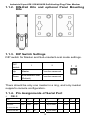
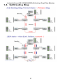
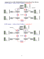
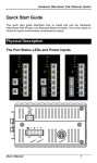
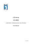
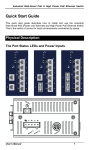
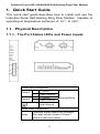
Industrial 2-port RS-232/422/485 Self-Healing Ring Fiber Modem
1. Quick Start Guide
This quick start guide describes how to install and use the
Industrial Serial Self-Healing Ring Fiber Modem. Capable of
operating at temperature extremes of -10℃ to +60℃.
1.1. Physical Description
1.1.1. The Port Status LEDs and Power Inputs
Power Input Assignment
+ 12-32VDC
Power1
- Power Ground
+ 12-32VDC
Power2
- Power Ground
Terminal Block
Earth Ground
Relay Alarm Assignment
*Warning signal disable for following:
Relay
The relay contact closes if Power1
and/or Power2 are failed.
1
Industrial 2-port RS-232/422/485 Self-Healing Ring Fiber Modem
LED
State
Indication
Power 1
Power 2
(Green)
Steady
Power on
Off
Power off
Status
(Green)
Steady
Functioned
Fault
(Orange)
Steady
Power or port link fails
Off
Well Functioned
Steady
Master Mode
Off
Off status
System
Flashing Reset
Machine mode
Master
(Green)
Sub-master/Local Steady
Local Mode
(Green)
Flashing Sub-master mode
Off
Off status
Serial port
Port 1 (TX/RX)
Port 2 (TX/RX)
Flashing Data transmitting
Ethernet port: 100Base-FX
P Ring
(Primary Ring)
(Green)
Steady
A valid connection through Primary path
Flashing Ethernet port data transmitting
Off
No valid connection established
S Ring
Steady
A valid connection through Secondary path
(Secondary Ring)
Flashing Ethernet port data transmitting
(Green)
Off
No valid connection established
There are Terminal Block power inputs can be used to power
up this device. Redundant power supplies function is
supported.
2
Industrial 2-port RS-232/422/485 Self-Healing Ring Fiber Modem
1.1.2. DIN-Rail Kits and optional Panel Mounting
Kits
1.1.3. DIP Switch Settings
DIP switch for Master and Sub-master/Local mode settings.
DIP
1
switch
Up
2
Master
Function reserved
Sub-master/Local
Down
1 2
Function reserved
(Default)
There should be only one master in a ring, and only master
supports console configuration.
1.1.4. Pin Assignments of Serial Port
y
DB-9
Pin
1
2
3
4
5
6
7
8
9
RS-232
DCD
RxD
TxD
DTR
Signal GND
DSR
RTS
CTS
RI
RS-422
TxD+
RxD-
RxD+
Signal GND
D-
D+
Signal GND
4-wire RS-485
2-wire RS-485
3
TxD-
Industrial 2-port RS-232/422/485 Self-Healing Ring Fiber Modem
1.2. Functional Description
y
y
y
y
y
y
y
y
Flexible
Serial
Ports:
Supports
2
ports
of
RS-232/422/485.
Dual LAN Ports: Supports network connection
Self-Healing Ring function.
Fiber Option: Supports single-mode and multi-mode fiber
optics for both LAN ports.
Redundant Power Input: Two Terminal Block power inputs
ensure the continuous electrical stability.
DNP3.0 transparency: Allows DNP protocol passed
through.
Flexible Installation Method: Aluminum housing with
panel and DIN-Rail mounting.
Warning: Inform user by relay output in case of power
failure.
Simple Configuration: Supports DIP switch for
Master/Local settings.
4
Industrial 2-port RS-232/422/485 Self-Healing Ring Fiber Modem
1.3. Console Configuration
•
•
Connect to the console port: Connect the DB9 straight
cable to the RS-232 serial port of the device and the
RS-232 serial port of the terminal or computer running the
terminal emulation application. Direct access to the
administration console is achieved by directly connecting
a terminal or a PC equipped with a terminal-emulation
program (such as HyperTerminal) to the console port.
Configuration settings of the terminal-emulation program:
Baud rate
Data bits
Parity
Stop bit
Flow control
19,200bps
8
none
1
none
5
Industrial 2-port RS-232/422/485 Self-Healing Ring Fiber Modem
1.4. Self-Healing Ring
6
Industrial 2-port RS-232/422/485 Self-Healing Ring Fiber Modem
7
Industrial 2-port RS-232/422/485 Self-Healing Ring Fiber Modem
2. Table of Contents
1.
Quick Start Guide..................................................................... 1
1.1.
Physical Description .................................................................................1
1.1.1.
1.1.2.
1.1.3.
1.1.4.
The Port Status LEDs and Power Inputs .....................................................................................1
DIN-Rail Kits and optional Panel Mounting Kits .......................................................................3
DIP Switch Settings ........................................................................................................................3
Pin Assignments of Serial Port ......................................................................................................3
1.2.
1.3.
1.4.
Functional Description.............................................................................4
Console Configuration .............................................................................5
Self-Healing Ring......................................................................................6
2.
3.
Table of Contents ...................................................................... 8
Introduction............................................................................... 9
3.1.
3.2.
Overview....................................................................................................9
Features .....................................................................................................9
4.
Getting Started........................................................................ 10
4.1.
4.2.
4.3.
Packaging ................................................................................................10
Interfaces .................................................................................................10
Console Configuration ...........................................................................12
5.
Console Configuration............................................................ 13
5.1.
Config Settings ........................................................................................13
5.1.1.
5.1.2.
5.1.3.
5.1.4.
5.1.5.
5.1.6.
5.1.7.
5.1.8.
5.1.9.
5.1.10.
5.1.11.
5.1.12.
5.1.13.
ProtocolTimeoutDetect Settings ..................................................................................................14
Baud Rate Settings........................................................................................................................15
Data Bit Settings ...........................................................................................................................15
Stop Bit Settings............................................................................................................................16
Parity Settings ...............................................................................................................................16
Mode Settings ................................................................................................................................17
Flow Control Settings ...................................................................................................................17
Use Delimiter 1 Settings ...............................................................................................................18
Use Delimiter 2 Settings ...............................................................................................................19
ForceTransmit Settings ................................................................................................................20
Save Config....................................................................................................................................20
Serial Status...................................................................................................................................21
Exit .................................................................................................................................................21
5.2.
5.3.
Serial Port Status....................................................................................21
Ring Status ..............................................................................................21
5.3.1.
5.3.2.
5.3.3.
All MACs .......................................................................................................................................21
Refresh Ring Status ......................................................................................................................21
Exit .................................................................................................................................................22
5.4.
5.5.
5.6.
5.7.
5.8.
Synch Config ...........................................................................................22
Reset To Default .....................................................................................22
Firmware Version...................................................................................23
Forward Delay ........................................................................................23
Synch Path...............................................................................................23
6.
Specifications........................................................................... 25
6.1.
6.2.
Overview..................................................................................................25
Pin Assignments......................................................................................26
8
Industrial 2-port RS-232/422/485 Self-Healing Ring Fiber Modem
3. Introduction
3.1. Overview
This Industrial Serial to Ethernet Fiber Modem is a two serial
ports to two Ethernet ports Industrial Self-Healing Ring Fiber
Modem. It is an easy and reliable solution for bringing your
serial based equipments to the Fast Ethernet networks. This
Industrial Serial to Ethernet Fiber Modem supports ring
topology and an ability of auto-switch to other data path when
either link path fails. The Self-Healing Ring solution ensures
the data is uninterrupted and in time notice administrator
when any link fails. This function provides redundant network
connection for the serial devices connected to this Industrial
Serial to Ethernet Fiber Modem.
3.2. Features
y
y
y
y
y
y
y
y
Flexible
Serial
Ports:
Supports
2
ports
of
RS-232/422/485.
Dual LAN Ports: Supports network connection
Self-Healing Ring function.
Fiber Option: Supports single-mode and multi-mode fiber
optics for both LAN ports.
Redundant Power Input: Two Terminal Block power inputs
ensure the continuous electrical stability.
DNP3.0 transparency: Allows DNP protocol passed
through.
Flexible Installation Method: Aluminum housing with
panel and DIN-Rail mounting.
Warning: Inform user by relay output in case of power
failure.
Simple Configuration: Supports DIP switch for
Master/Local settings.
9
Industrial 2-port RS-232/422/485 Self-Healing Ring Fiber Modem
4. Getting Started
4.1. Packaging
y
y
y
Industrial Serial to Ethernet Fiber Modem x 1
Industrial Serial to Ethernet Fiber Modem Quick Start
Guide x 1
Product CD containing user’s manual x 1
4.2. Interfaces
Industrial Serial to Ethernet Fiber Modem Interfaces
LED
State
Indication
Power 1
Power 2
(Green)
Steady
Power on
Off
Power off
Status
(Green)
Steady
Functioned
Fault
(Orange)
Steady
Power or port link fails
Off
Well Functioned
System
Flashing Reset
Machine mode
10
Industrial 2-port RS-232/422/485 Self-Healing Ring Fiber Modem
Master
(Green)
Steady
Master Mode
Off
Off status
Sub-master/Local Steady
Local Mode
(Green)
Flashing Sub-master mode
Off
Off status
Serial port
Port 1 (TX/RX)
Port 2 (TX/RX)
Flashing Data transmitting
Ethernet port: 100Base-FX
P Ring
(Primary Ring)
(Green)
Steady
A valid connection through Primary path
Flashing Ethernet port data transmitting
Off
No valid connection established
S Ring
Steady
A valid connection through Secondary path
(Secondary Ring)
Flashing
Ethernet
port data transmitting
(Green)
Off
No valid connection established
Power Input Assignment
+ 12-32VDC
Power1
- Power Ground
+ 12-32VDC
Power2
- Power Ground
Terminal Block
Earth Ground
Relay Alarm Assignment
*Warning signal disable for following:
Relay
The relay contact closes if Power1
and/or Power2 are failed.
11
Industrial 2-port RS-232/422/485 Self-Healing Ring Fiber Modem
4.3. Console Configuration
•
•
Connect to the console port: Connect the DB9 straight
cable to the RS-232 serial port of the device and the
RS-232 serial port of the terminal or computer running the
terminal emulation application. Direct access to the
administration console is achieved by directly connecting
a terminal or a PC equipped with a terminal-emulation
program (such as HyperTerminal) to the console port.
Configuration settings of the terminal-emulation program:
Baud rate
Data bits
Parity
Stop bit
Flow control
19,200bps
8
none
1
none
12
Industrial 2-port RS-232/422/485 Self-Healing Ring Fiber Modem
5. Console Configuration
Command page
5.1. Config Settings
Please type “1” (Config Settings) and press <enter> to enter
“Serial Communication Parameter Settings” page.
Serial Communication Parameter Settings
[1]
ProtocolTimeoutDetect Settings
[2]
Baud Rate Settings
[3]
Data Bit Settings
[4]
Stop Bit Settings
[5]
Parity Settings
[6]
Mode Settings
[7]
Flow Control Settings
[8]
Use Delimiter 1 Settings
[9]
Use Delimiter 2 Settings
[10] ForceTransmit Settings
[11] Save Config
[12] Serial Status
13
Industrial 2-port RS-232/422/485 Self-Healing Ring Fiber Modem
[Q]
Exit
5.1.1. ProtocolTimeoutDetect Settings
Please type “1” (ProtocolTimeoutDetect Settings) and press
<enter> to enter “Protocol Timeout Detect” page. The default
ProtocolTimeoutDetect Settings is “Disable”.
Protocol Timeout Detect
[1]
Enable
[2]
Disable
[Q] Exit
1.
[1] – Enable:
Please type “1” (Enable) and press <enter> to enter “Set
Protocol Timeout” page and enable Industrial Serial
Self-Healing Ring Fiber Modem to automatically test the TCP
connection to remote host. If the TCP connection is idle, the
TCP connection will be closed and the serial port will be freed
for other hosts.
Set Protocol Timeout
[0] ~ [99] ms
0 ~ 99 ms
[Q]
Exit
[0] ~ [99] ms:
Type a period of Protocol Timeout assigned to the serial port
on the Industrial Serial Self-Healing Ring Fiber Modem. The
connection will be closed and the serial port will be freed for
connection with other hosts when serial port stops data
transmission for a defined period of time (Protocol Timeout).
The default Protocol Timeout is 0 ms.
[Q] - Exit:
Please type “Q” and press <enter> to exit to “Serial
Communication Parameter Settings” page.
2.
[2] – Disable:
Please type “2” (Disable) and press <enter> to disable
14
Industrial 2-port RS-232/422/485 Self-Healing Ring Fiber Modem
Industrial Serial Self-Healing Ring Fiber Modem
automatically test the TCP connection to remote host.
to
3.
[Q] - Exit:
Please type “Q” (Exit) and press <enter> to exit to “Serial
Communication Parameter Settings” page.
5.1.2. Baud Rate Settings
Please type “2” (Baud Rate Settings) and press <enter> to
enter “Baud Rate” page. The default Baud Rate Settings is
9600 bps.
Baud rate
[1]
50
[2]
75
[3]
110
[4]
134
[5]
150
[6]
200
[7]
300
[8]
600
[9]
1200
[10] 2400
[11]
[12]
[13]
[14]
[15]
[16]
[17]
[18]
[Q]
4800
9600
19200
38400
57600
115200
230400
460800
Exit
1.
Baud Rate:
Please type “1” ~ “18” (50 ~ 460800 bps) and press <enter>
to set Baud rate for serial port.
2.
[Q] - Exit:
Please type “Q” (Exit) and press <enter> to exit to “Serial
Communication Parameter Settings” page.
5.1.3. Data Bit Settings
Please type “3” (Data Bit Settings) and press <enter> to enter
“Data bits” page. The default Data Bit Settings is 8 bits.
Data bits
15
Industrial 2-port RS-232/422/485 Self-Healing Ring Fiber Modem
[1]
[2]
[3]
[4]
[Q]
5
6
7
8
Exit
1.
Data bits:
Please type “1” ~ “4” (5 ~ 8 bits) and press <enter> to set
Data bits for serial port.
2.
[Q] - Exit:
Please type “Q” (Exit) and press <enter> to exit to “Serial
Communication Parameter Settings” page.
5.1.4. Stop Bit Settings
Please type “4” (Stop Bit Settings) and press <enter> to enter
“Stop bits” page. The default Stop Bit Settings is 1 bit.
Stop bits
[1]
1
[2]
2
[Q]
Exit
1.
Stop bits:
Please type “1” ~ “2” (1 ~ 2 bits) and press <enter> to set Stop
bits for serial port.
2.
[Q] - Exit:
Please type “Q” (Exit) and press <enter> to exit to “Serial
Communication Parameter Settings” page.
5.1.5. Parity Settings
Please type “5” (Parity Settings) and press <enter> to enter
“Parity” page. The default Parity Settings is “None”.
Parity
[1]
None
16
Industrial 2-port RS-232/422/485 Self-Healing Ring Fiber Modem
[2]
[3]
[4]
[5]
[Q]
Odd
Even
Mark
Space
Exit
1.
Parity:
Please type “1” ~ “5” (None, Odd, Even, Mark, or Space) and
press <enter> to set Parity for serial port.
2.
[Q] - Exit:
Please type “Q” (Exit) and press <enter> to exit to “Serial
Communication Parameter Settings” page.
5.1.6. Mode Settings
Please type “6” (Mode Settings) and press <enter> to enter
“Mode” page. The default Mode Settings is “RS232”.
Mode
[1]
[2]
[3]
[Q]
RS232
RS485
RS422
Exit
1.
Mode:
Please type “1” ~ “3” (RS232, RS485, or RS422) and press
<enter> to set Mode for serial port.
2.
[Q] - Exit:
Please type “Q” (Exit) and press <enter> to exit to “Serial
Communication Parameter Settings” page.
5.1.7. Flow Control Settings
Please type “7” (Flow Control Settings) and press <enter> to
enter “Flow control” page. The default Flow Control Settings is
“None”.
17
Industrial 2-port RS-232/422/485 Self-Healing Ring Fiber Modem
Flow control
[1]
None
[2]
Hardware
[3]
Software
[Q]
Exit
1.
Flow control:
Please type “1” ~ “3” (None, Hardware, or Software) and
press <enter> to set Flow control for serial port.
2.
[Q] - Exit:
Please type “Q” (Exit) and press <enter> to exit to “Serial
Communication Parameter Settings” page.
5.1.8. Use Delimiter 1 Settings
Please type “8” (Use Delimiter 1 Settings) and press <enter>
to enter “Delimiter 1” page. The default Use Delimiter 1
Settings is “Disable”. Enable Delimiter 1. The data will be
transmitted if the Delimiter 1 is received. Enable Delimiter 1
and Delimiter 2. The data will be transmitted if the Delimiter 1
and Delimiter 2 are received.
Delimiter 1
[1]
Enable
[2]
Disable
[Q] Exit
1.
[1] – Enable:
Please type “1” (Enable) and press <enter> to enter “Set
Delimiter 1” page.
Set Delimiter 1
[00] ~ [ff] hex
[Q]
[00] ~ [ff]
Exit
[00] ~ [ff] hex:
Please type “00” ~ “ff” and press <enter> to set Delimiter 1 for
serial port.
18
Industrial 2-port RS-232/422/485 Self-Healing Ring Fiber Modem
[Q] - Exit:
Please type “Q” and press <enter> to exit to “Serial
Communication Parameter Settings” page.
2.
[2] – Disable:
Please type “2” (Disable) and press <enter> to disable Use
Delimiter 1 Settings.
3.
[Q] - Exit:
Please type “Q” (Exit) and press <enter> to exit to “Serial
Communication Parameter Settings” page.
5.1.9. Use Delimiter 2 Settings
Please type “9” (Use Delimiter 2 Settings) and press <enter>
to enter “Delimiter 2” page. The default Use Delimiter 2
Settings is “Disable”. Enable Delimiter 1. The data will be
transmitted if the Delimiter 1 is received. Enable Delimiter 1
and Delimiter 2. The data will be transmitted if the Delimiter 1
and Delimiter 2 are received.
Delimiter 2
[1]
Enable
[2]
Disable
[Q] Exit
1.
[1] – Enable:
Please type “1” (Enable) and press <enter> to enter “Set
Delimiter 2” page.
Set Delimiter 2
[00] ~ [ff] hex
[Q]
[00] ~ [ff]
Exit
[00] ~ [ff] hex:
Please type “00” ~ “ff” and press <enter> to set Delimiter 2 for
serial port.
[Q] - Exit:
19
Industrial 2-port RS-232/422/485 Self-Healing Ring Fiber Modem
Please type “Q” and press <enter> to exit to “Serial
Communication Parameter Settings” page.
2.
[2] – Disable:
Please type “2” (Disable) and press <enter> to disable Use
Delimiter 2 Settings.
3.
[Q] - Exit:
Please type “Q” (Exit) and press <enter> to exit to “Serial
Communication Parameter Settings” page.
5.1.10. ForceTransmit Settings
Please type “10” (ForceTransmit Settings) and press <enter>
to enter “ForceTransmit” page. The default ForceTransmit
Settings is 0 ms. Specify ForceTransmit for the serial port.
The data will be transmitted when the ForceTransmit is
reached.
ForceTransmit
[0] ~ [999] ms
[Q]
0 ~ 999 ms
Exit
1.
ForceTransmit:
Please type “0” ~ “999” (0 ~ 999 ms) and press <enter> to set
ForceTransmit for serial port.
2.
[Q] - Exit:
Please type “Q” (Exit) and press <enter> to exit to “Serial
Communication Parameter Settings” page.
5.1.11. Save Config
Please type “11” (Save Config) and press <enter> to save
configuration. Then press any key to exit to “Serial
Communication Parameter Settings” page.
20
Industrial 2-port RS-232/422/485 Self-Healing Ring Fiber Modem
5.1.12. Serial Status
Please type “12” (Serial Status) and press <enter> to show
status of serial port. Then press any key to exit to “Serial
Communication Parameter Settings” page.
5.1.13. Exit
Please type “Q” (Exit) and press <enter> to exit to
“Command” page.
5.2. Serial Port Status
Please type “2” (Serial Port Status) and press <enter> to
show status of serial port. Then press any key to exit to
“Command” page.
5.3. Ring Status
Please type “3” (Ring Status) and press <enter> to enter
“MACs on the ring” page.
MACs on the ring
[1]
All MACs
[2]
Refresh ring status
[Q]
Exit
5.3.1. All MACs
Please type “1” (All MACs) and press <enter> to show all
MAC addresses on the ring.
5.3.2. Refresh Ring Status
Please type “2” (Refresh ring status) and press <enter> to
refresh ring status. Then press any key to exit to “MACs on
the ring” page.
21
Industrial 2-port RS-232/422/485 Self-Healing Ring Fiber Modem
5.3.3. Exit
Please type “Q” (Exit) and press <enter> to exit to
“Command” page.
5.4. Synch Config
Please type “4” (Synch Config) and press <enter> to enter
“Synch Config” page.
Synch Config
[1]
Yes
[2]
No
1.
[1] – Yes:
Please type “1” (Yes) and press <enter> to synchronize
configuration. Then press any key to exit to “Command” page.
2.
[2] – No:
Please type “2” (No) and press <enter> to exit to “Command”
page.
5.5. Reset To Default
Please type “5” (Reset to default) and press <enter> to enter
“Reset to default” page.
Reset to default
[1]
Yes
[2]
No
1.
[1] – Yes:
Please type “1” (Yes) and press <enter> to reset to default.
This Industrial Serial to Ethernet Fiber Modem will reboot and
back to “Command” page.
22
Industrial 2-port RS-232/422/485 Self-Healing Ring Fiber Modem
2.
[2] – No:
Please type “2” (No) and press <enter> to exit to “Command”
page.
5.6. Firmware Version
Please type “6” (Firmware Version) and press <enter> to
show firmware version. Then press any key to exit to
“Command” page.
5.7. Forward Delay
Please type “7” (Forward Delay) and press <enter> to enter
“Set Forward Delay” page. The default Forward Delay is 10
seconds.
Set Forward Delay
[10] ~ [100] second
[Q]
10 ~ 100 seconds
Exit
1.
Set Forward Delay:
Please type “10” ~ “100” (10 ~ 100 seconds) and press
<enter> to set Forward Delay for serial port.
2.
[Q] - Exit:
Please type “Q” (Exit) and press <enter> to exit to
“Command” page.
5.8. Synch Path
Please type “8” (Synch Path) and press <enter> to enter
“Synch Path” page.
Synch Path
[1]
Yes
[2]
No
1.
[1] – Yes:
23
Industrial 2-port RS-232/422/485 Self-Healing Ring Fiber Modem
Please type “1” (Yes) and press <enter> to synchronize path.
2.
[2] – No:
Please type “2” (No) and press <enter> to exit to “Command”
page.
24
Industrial 2-port RS-232/422/485 Self-Healing Ring Fiber Modem
6. Specifications
6.1. Overview
Applicable
Standards
Switching Method
Forwarding Rate
100Base-FX
Performance
Cable
100Base-FX
Serial Port
Interface
Connector
Serial
Communication
Parameters
Parity
Data Bits
Stop Bit
Flow Control
Speed
LED Indicators
Dimensions
Net Weight
Power Input
Power
Consumption
Operating
Temperature
Storage
Temperature
Humidity
Emission
Compliance
IEEE 802.3u 100Base-FX
Store-and-Forward
200Mbps full-duplex
148,810pps for 100Mbps
50 or 62.5/125µm multi-mode fiber (1310nm) up to 2km
9 or 10/125µm single-mode fiber (1310nm) up to 75km
RS-232/422/485
DB9 (2-port RS-232/422/485)
None, Even, Odd, Mark, Space
5, 6, 7, 8
1, 2
None, Hardware, Software
50bps to 460.8Kbps
Per unit – Power status (Power 1, 2), Status, Fault, Master,
Sub-master/Local
Ethernet port – P Ring (Primary Ring), S Ring (Secondary
Ring)
Serial port – Port 1 TX/RX, Port 2 TX/RX
100mm (W) x 125mm (D) x 30mm (H)
(3.94” (W) x 4.92” (D) x 1.18” (H))
0.3Kg (0.66lb.)
Terminal Block: 12~32VDC
5.76W Max. 0.48A @ 12VDC, 0.24A @ 24VDC
-10℃ to 60℃ (14℉ to 140℉)
-20℃ to 85℃ (-4℉ to 185℉)
5%-95% non-condensing
CE Mark Class A
FCC Part 15 Class A
VCCI Class A
25
Industrial 2-port RS-232/422/485 Self-Healing Ring Fiber Modem
6.2. Pin Assignments
Pin assignments for serial port
DB-9:
Pin#
RS-232
1
2
3
4
5
6
7
8
9
DCD
RxD
TxD
DTR
Signal GND
DSR
RTS
CTS
RI
RS-422
4-wire RS-485
TxD+
RxDRxD+
Signal GND
TxD-
26
2-wire RS-485
DD+
Signal GND