1
ControlNet
Communication
Interface Module
1770-KFC15
User Manual
Important User Information
Solid state equipment has operational characteristics differing from those of electromechanical equipment.
Safety Guidelines for the Application, Installation and Maintenance of Solid State Controls (Publication
SGI-1.1 available from your local Rockwell Automation sales office or online at
http://www.ab.com/manuals/gi) describes some important differences between solid state equipment and
hard-wired electromechanical devices. Because of this difference, and also because of the wide variety of
uses for solid state equipment, all persons responsible for applying this equipment must satisfy themselves
that each intended application of this equipment is acceptable.
In no event will Rockwell Automation, Inc. be responsible or liable for indirect or consequential damages
resulting from the use or application of this equipment.
The examples and diagrams in this manual are included solely for illustrative purposes. Because of the many
variables and requirements associated with any particular installation, Rockwell Automation, Inc. cannot
assume responsibility or liability for actual use based on the examples and diagrams.
No patent liability is assumed by Rockwell Automation, Inc. with respect to use of information, circuits,
equipment, or software described in this manual.
Reproduction of the contents of this manual, in whole or in part, without written permission of Rockwell
Automation, Inc. is prohibited.
Throughout this manual we use notes to make you aware of safety considerations.
WARNING
Identifies information about practices or circumstances that can cause an explosion in a
hazardous environment, which may lead to personal injury or death, property damage,
or economic loss.
IMPORTANT
Identifies information that is critical for successful application and understanding of the
product.
ATTENTION
Identifies information about practices or circumstances that can lead to personal injury
or death, property damage, or economic loss. Attentions help you:
• identify a hazard
• avoid a hazard
• recognize the consequence
SHOCK HAZARD
BURN HAZARD
Labels may be located on or inside the equipment to alert people that dangerous
voltage may be present.
Labels may be located on or inside the equipment to alert people that surfaces may be
dangerous temperatures.
Preface
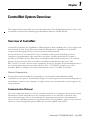
The 1770-KFC15 communication interface module provides a communication link between
a ControlNet cable system and devices with a serial or parallel port, such as programming
terminals, portable computers, and other serial/parallel devices.
Purpose of the Manual
Throughout this manual we refer to the 1770-KFC15 communication interface module as
simply ‘the module’.
Use this manual to:
• install and configure the module
• understand how the module communicates on the network (procedures and
protocols)
• troubleshoot for problems
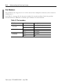
Related Publications
These publications contain information related to the 1770-KFC15 Communication Interface
module:
Publication Title
Publication Number
ControlNet Cable System Planning and Installation Manual
CNET-IN002
ControlNet Cable System Component List
AG-PA002
DF1 Protocol and Command Set Reference Manual
1770-RM516
Industrial Automation Wiring and Grounding Guidelines
1770-4.1
PLC-5 Family Programmable Controllers Hardware Installation Manual
1785-6.6.1
Publication 1770-UM520C-EN-P - July 2004
P-2
Related Products
The module creates an interface between the ControlNet cable system and devices with a
serial or parallel port. It has been verified to work with these products:
• Allen-Bradley ControlNet taps
(1786-TPR, 1786-TPS, 1786-TPYR, and 1786-TPYS)
• Allen-Bradley high voltage AC and DC type repeaters
(1786-RPT and 1786- RPTD)
• Allen-Bradley PLC-5 programmable controllers (1785-L20C15, -L40C15, -L60C15,
-L80C15)
• Allen-Bradley computer interface cards (1784-KTC15 and 1784-KTCX15)
• Allen-Bradley 1794 Flex I/O Adapters (1794-ACN15, 1794-ACNR15)
• Allen-Bradley 1771 I/O Adapters (1771-ACN15, 1771-ACNR15)
• Allen-Bradley ControlLogix ControlNet Bridge Module (1756-CNB and
1756-CNBR)
• Rockwell Software’s RSLogix 5, RSView 32, RSLinx, RSNetWorx, RSLogix 500,
RSLogix 5000
• Network Access cable (1786-CP)
Other ControlNet devices and software that comply with the ControlNet Network
specifications can also be used with the module.
Publication 1770-UM520C-EN-P - July 2004
P-3
Terms and Abbreviations
This term:
Means:
1747-KFC15
SLC-based module
1756-CNB
a 1756-CNB or 1756-CNBR module; a ControlLogix backplane to ControlNet bridge
1770-KFC15
referred to herein as the module
a.k.a.
also known as
ACK
a DF1 or ControlNet acknowledgement
ControlNet
the communication architecture that allows the exchange of messages between
devices that follow the ControlNet specifications
It is a real-time, control-layer network that provides high-speed transport for both
time-critical I/O and messaging data. A ControlNet cable system can be either
single or redundant media.
DF1
DF1 protocol is an Allen-Bradley RS-232 proprietary data-link layer protocol that
combines features of subcategories D1 (data transparency) and F1 (two-way
simultaneous transmission with embedded responses) of ANSI x3.28
specification. The KFC uses DF1 protocol to communicate on the serial port.
DH+
Data Highway Plus network; existing Allen-Bradley peer-to-peer network for
messaging and program upload/download
DH+ PCCC message
a PCCC message that originated from a device on a DH+ network
DHRIO
Data Highway and Remote I/O
DST
the destination address on a DF1 link
full duplex
simultaneous send/receive between devices, point-to-point
half duplex
data transmission in one direction at a time, usually point-to-multipoint
NAK
a DF1 negative acknowledgement
NAP
network access port; input/output (RJ-45 style) connector for a programming
terminal to gain full access to the network
network
a collection of connected nodes (end devices). The connection paths between any
pair of nodes can include repeaters, routers, bridges and gateways.
network address
the network address of a node on the ControlNet cable system. This address must
be in the range of 1 to 99 (decimal) and be unique to that subnet. A subnet can
contain a maximum of 99 nodes.
new KFC
Version 4.2 or later of the KFC firmware
node
any physical device connecting to the ControlNet cable system that requires a
network address in order to function on the network.
NUT
network update time; the rate at which access to the ControlNet network is
granted
Publication 1770-UM520C-EN-P - July 2004
P-4
This term:
Means:
old KFC
Any 1747-KFC15 or 1770-KFC15 firmware released before v4.2, including version
2.2 (a.k.a. version B/B) and older firmware
parallel port
input/output port for a device that transmits multiple data and control bits over
wires connected in parallel
PCCC
Programmable Controller Communication Commands; an Allen-Bradley
communication protocol used on the Data Highway Plus network
repeater
a two-port active physical layer component that reconstructs all traffic it hears on
one network segment side and retransmits it to another network segment side.
Repeaters allow for extensions in network distance, conversion to alternate media
(coaxial cable, fiber, etc.) and altering the topology of the network.
RIO
Remote Input/Output; an Allen-Bradley remote input/output link that supports
remote, time-critical, I/O and control communication between a master PLC
controller and its remote I/O and adapter mode slave processors
RS-232C port
a serial port that complies with accepted industry standards for serial
communications connections
SRC
The source address on a DF1 link
segment
trunkline sections connected via taps with terminators at each end, and with no
repeaters
serial port
input/output connector for a device that transmits data and control bits
sequentially over a single transmission line. (See RS-232C port.)
standard PCCC message
A PCCC message that originated from a device that is not on a DH+ network
subnet
network segments connected by repeaters to make up one ControlNet network
tap
the connection device between any ControlNet device and the trunkline. A tap is
required for each node and for both sides of each repeater.
terminator
a special circuit that prevents signal reflections from occurring at the end of a
cable
trunkline
the bus or central part of a cable system
trunkline section
a length of trunkline cable between any two taps
Publication 1770-UM520C-EN-P - July 2004
P-5
ATTENTION
!
Environment and Enclosure
This equipment is intended for use in a Pollution Degree 2 industrial
environment, in overvoltage Category II applications (as defined in IEC
publication 60664-1), at altitudes up to 2000 meters without derating.
This equipment is considered Group 1, Class A industrial equipment
according to IEC/CISPR Publication 11. Without appropriate
precautions, there may be potential difficulties ensuring electromagnetic
compatibility in other environments due to conducted as well as radiated
disturbance.
This equipment is supplied as “enclosed” equipment. It should not
require additional system enclosure when used in locations consistent
with the enclosure type ratings stated in the Specifications section of this
publication. Subsequent sections of this publication may contain
additional information regarding specific enclosure type ratings, beyond
what this product provides, that are required to comply with certain
product safety certifications.
NOTE: See NEMA Standards publication 250 and IEC publication
60529, as applicable, for explanations of the degrees of protection
provided by different types of enclosure. Also, see the appropriate
sections in this publication, as well as the Allen-Bradley publication
1770-4.1 (“Industrial Automation Wiring and Grounding Guidelines”),
for additional installation requirements pertaining to this equipment.
WARNING
!
Preventing Electrostatic Discharge
This equipment is sensitive to electrostatic discharge, which can cause
internal damage and affect normal operation. Follow these guidelines
when you handle this equipment:
•
•
•
•
•
•
Touch a grounded object to discharge potential static.
Wear an approved grounding wrist strap.
Do not touch connectors or pins on component boards.
Do not touch circuit components inside the equipment.
If available, use a static-safe workstation.
When not in use, store the equipment in appropriate static-safe
packaging.
Publication 1770-UM520C-EN-P - July 2004
P-6
Notes:
Publication 1770-UM520C-EN-P - July 2004
Table of Contents
Chapter 1
ControlNet System Overview
Overview of ControlNet. . . . . . . . . . . . . . . . . . . . . . . . . . . . . . . . . . . .
Communication Protocol . . . . . . . . . . . . . . . . . . . . . . . . . . . . . . . . . . .
Understanding the ControlNet Architecture . . . . . . . . . . . . . . . . . . . .
Planning the Host Cable System . . . . . . . . . . . . . . . . . . . . . . . . . . . . .
1-1
1-1
1-2
1-3
Chapter 2
Introducing the Module
Overview of the 1770-KFC15 Module . . . . . . . . . . . . . . . . . . . . . . . . 2-1
Chapter 3
Installing the Module
Electrostatic Damage . . . . . . . . . . . . . . . . . . . . . . . . . . . . . . . . . . . . . . . . . .
Overview of the Installation Procedure . . . . . . . . . . . . . . . . . . . . . . . . . . .
Connecting to a Host through the RS-232C Port . . . . . . . . . . . . . . . .
RS- 232C Baud Rates . . . . . . . . . . . . . . . . . . . . . . . . . . . . . . . . . . . . . .
Cables. . . . . . . . . . . . . . . . . . . . . . . . . . . . . . . . . . . . . . . . . . . . . . . . . . .
Connector . . . . . . . . . . . . . . . . . . . . . . . . . . . . . . . . . . . . . . . . . . . . . . .
RS-232C Activity Indicator. . . . . . . . . . . . . . . . . . . . . . . . . . . . . . . . . .
Connecting to a Host through the Parallel Port . . . . . . . . . . . . . . . . . . . . .
Cables. . . . . . . . . . . . . . . . . . . . . . . . . . . . . . . . . . . . . . . . . . . . . . . . . . .
Connector . . . . . . . . . . . . . . . . . . . . . . . . . . . . . . . . . . . . . . . . . . . . . . .
Parallel Port Activity Indicator . . . . . . . . . . . . . . . . . . . . . . . . . . . . . . .
Connecting a Device to the Network Access Port. . . . . . . . . . . . . . . . . . .
Cables. . . . . . . . . . . . . . . . . . . . . . . . . . . . . . . . . . . . . . . . . . . . . . . . . . .
Connecting to the AC Power Supply . . . . . . . . . . . . . . . . . . . . . . . . . . . . .
Connecting to the ControlNet Cable System . . . . . . . . . . . . . . . . . . . . . . .
Attaching the Module to a Wall or Mounting Bracket. . . . . . . . . . . . . . . .
3-1
3-2
3-2
3-2
3-3
3-3
3-3
3-4
3-4
3-4
3-4
3-4
3-4
3-5
3-6
3-7
Publication 1770-UM520C-EN-P - July 2004
2
Table of Contents
Chapter 4
Configuring the Module
Overview of Configuration Procedures . . . . . . . . . . . . . . . . . . . . . . . . . . . 4-1
Displays . . . . . . . . . . . . . . . . . . . . . . . . . . . . . . . . . . . . . . . . . . . . . . . . . 4-1
Pushbuttons. . . . . . . . . . . . . . . . . . . . . . . . . . . . . . . . . . . . . . . . . . . . . . 4-2
Configuring the Module by Using Pushbuttons . . . . . . . . . . . . . . . . . 4-3
Verifying the Communication Parameters. . . . . . . . . . . . . . . . . . . . . 4-13
1770-KFC15 Diagnostic Counters . . . . . . . . . . . . . . . . . . . . . . . . . . . . . . 4-14
Reading 1770-KFC15 Counters With a Diagnostic Command. . . . . . . . 4-14
Chapter 5
Understanding the Extra-hop Feature
Method 1: No Configuration. . . . . . . . . . . . . . . . . . . . . . . . . . . . . . . . . . . .
Method 2: Configure a Path Using the Pushbuttons
and 7-segment Display. . . . . . . . . . . . . . . . . . . . . . . . . . . . . . . . . . . . . . . .
Path Length . . . . . . . . . . . . . . . . . . . . . . . . . . . . . . . . . . . . . . . . . . . . . .
Port Numbers . . . . . . . . . . . . . . . . . . . . . . . . . . . . . . . . . . . . . . . . . . . .
Address/Slot Number . . . . . . . . . . . . . . . . . . . . . . . . . . . . . . . . . . . . .
5-2
5-3
5-3
5-4
5-5
Chapter 6
Communicating with the Module
DF1 Communication . . . . . . . . . . . . . . . . . . . . . . . . . . . . . . . . . . . . . . . . . .
Serial Communication . . . . . . . . . . . . . . . . . . . . . . . . . . . . . . . . . . . . . . . . .
Parallel Communication . . . . . . . . . . . . . . . . . . . . . . . . . . . . . . . . . . . .
Embedded Responses . . . . . . . . . . . . . . . . . . . . . . . . . . . . . . . . . . . . . . . . .
Message Reply Time-out . . . . . . . . . . . . . . . . . . . . . . . . . . . . . . . . . . . . . . .
Default DF1 Address. . . . . . . . . . . . . . . . . . . . . . . . . . . . . . . . . . . . . . . . . .
DF1 SRC and DST Address . . . . . . . . . . . . . . . . . . . . . . . . . . . . . . . . . . . .
RSLinx DF1 Driver Anomaly . . . . . . . . . . . . . . . . . . . . . . . . . . . . . . . . . . .
Auto-recovery. . . . . . . . . . . . . . . . . . . . . . . . . . . . . . . . . . . . . . . . . . . . . . . .
Message Buffers . . . . . . . . . . . . . . . . . . . . . . . . . . . . . . . . . . . . . . . . . . . . . .
6-1
6-2
6-4
6-5
6-6
6-6
6-7
6-8
6-9
6-9
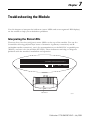
Chapter 7
Troubleshooting the Module
Interpreting the Status LEDs . . . . . . . . . . . . . . . . . . . . . . . . . . . . . . . . . . . 7-1
Publication 1770-UM520C-EN-P - July 2004
Table of Contents
3
Appendix A
Product Specifications
Appendix B
Cabling and Pinouts
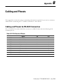
Cabling and Pinouts for RS-232C Connection. . . . . . . . . . . . . . . . . . . . . B-1
Cabling and Pinouts for Parallel Port Connection . . . . . . . . . . . . . . B-6
Appendix C
DF1 Diagnostic Command Support
Diagnostic Loop. . . . . . . . . . . . . . . . . . . . . . . . . . . . . . . . . . . . . . . . . . . . .
Diagnostic Read Counters . . . . . . . . . . . . . . . . . . . . . . . . . . . . . . . . . . . . .
Diagnostic Status . . . . . . . . . . . . . . . . . . . . . . . . . . . . . . . . . . . . . . . . . . . .
Diagnostic Counter Reset . . . . . . . . . . . . . . . . . . . . . . . . . . . . . . . . . . . . .
1747-KFC15 Meters. . . . . . . . . . . . . . . . . . . . . . . . . . . . . . . . . . . . . . . . . .
C-2
C-2
C-5
C-6
C-6
Appendix D
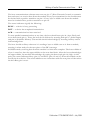
Writing a Parallel Communication Driver
DF1 Parallel Communication . . . . . . . . . . . . . . . . . . . . . . . . . . . . . . . . . . D-1
Data Transmission . . . . . . . . . . . . . . . . . . . . . . . . . . . . . . . . . . . . . . . D-4
Index
Publication 1770-UM520C-EN-P - July 2004
4
Table of Contents
Publication 1770-UM520C-EN-P - July 2004
Chapter
1
ControlNet System Overview
This chapter briefly describes the network architecture. For detailed information, refer to the
ControlNet Cable System Planning and Installation Manual, CNET-IN002.
Overview of ControlNet
ControlNet combines the capabilities of Data Highway Plus and Remote I/O in a single local
area network (LAN). It provides time-critical communication capabilities for real-time
control, and messaging services for peer-to-peer communication.
Several devices can be connected to the ControlNet cable system including personal
computers, programmable logic controllers, modems, variable speed drivers, operator
interfaces, and other devices with direct ControlNet cable system connections. To connect
directly, devices must be able to handle ControlNet communication protocol. The
PLC-5/40C15 is such a device. Some equipment, however, requires an intermediate device to
act as an interface between it and the network. The 1770-KFC15 module acts as this
interface. Refer to Chapter 2 for more information on the 1770-KFC15 module.
Physical Characteristics
The physical network media for ControlNet is coaxial cable with redundant media
connections as an option. The allowable length of a cable segment in the network depends on
the number of nodes in the segment. A single subnet can accommodate several segments by
using repeaters.
Communication Protocol
The most important function of the ControlNet network is to transport time-critical control
information. Other information is also transported but is not allowed to interfere with
time-critical messages. This is done through a communication protocol that determines
access to the ControlNet network using a time-slice access algorithm. Access to the network
occurs at a user-configurable period called the network update time (NUT).
Publication 1770-UM520C-EN-P - July 2004
1-2
ControlNet System Overview
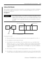
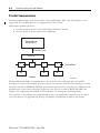
The NUT is divided into three parts:
Scheduled—every node is guaranteed one opportunity to transmit
Unscheduled—remaining time is divided among all nodes on a round-robin basis. This
rotation of access repeats until the time allotted to the unscheduled portion is used up. The
amount of time available for the unscheduled portion is determined by the traffic load of the
scheduled portion.
Maintenance—the moderator node (the one with the lowest address) transmits information
to keep the other nodes synchronized in time
boundary moves depending
on scheduled traffic load
Start
• reserved for
scheduled traffic
• each device transmits
only once
• unscheduled traffic
• reserved for
network maintenance
31446-M
The part of the interval in which any given data will be sent depends on its priority,
of which there are two levels:
Scheduled Data—time-critical information that must be sent at a fixed and repetitive rate is
sent exclusively in the scheduled portion of the NUT.
Unscheduled Data—information that does not have strict time constraints. It is sent only if
no data is waiting to be sent at a higher priority.
The 1770-KFC15 module supports non-time-critical messaging and programming
data, and sends only unscheduled data.
Understanding the ControlNet Architecture
The ControlNet cable system provides the flexibility to design a communication
network for your application. To take advantage of this flexibility, you should
spend enough time planning how to install your cable system before assembling
any of the hardware. Consult the ControlNet Cable System Planning and Installation
Manual, CNET-IN002, for a full description of the cable system and detailed installation
instructions.
Publication 1770-UM520C-EN-P - July 2004
ControlNet System Overview
1-3
Planning the Host Cable System
A serial or parallel host (computer, controller, or other device) can connect to the
module through either the parallel or RS-232C serial port. Both ports on the module
cannot be active at the same time so you must decide which port is the most
appropriate for your application. This decision determines the cabling and
hardware requirements for your system.
Communication between either a parallel or serial host and the module is carried
out using Allen-Bradley’s proprietary DF1 protocol. DF1 is a full- or half-duplex
protocol that carries messages intact over a link. The protocol delimits messages,
detects and signals errors, retries after errors, and controls message flow. In a
typical network, as discussed in this manual, the host is the master station and the
module is the slave. For a complete description of the DF1 protocol, refer to the
DF1 Protocol and Command Set Reference Manual, 1770-RM516.
IMPORTANT
Firmware V4.2 and later do not support the parallel port.
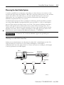
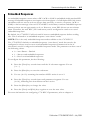
Planning for an RS-232C Serial Port
Serial port communication can take place in either full- or half-duplex mode. If a
single module per serial host is used, either half-duplex or full-duplex
communication can take place. Since it is faster and easier to configure, full-duplex
is always preferred over half duplex.
Host
RS-232C Link
1770-KFC15
ControlNet
ControlNet Devices
31348-M
Publication 1770-UM520C-EN-P - July 2004
1-4
ControlNet System Overview
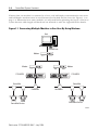
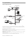
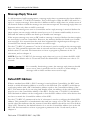
If more than one module is connected to a host, only half-duplex communication can occur
and half-duplex modems must be used between the module and the host. See Figure 1.1 on
page 1-4. Determine how many modules you will need before planning the layout of the host
system because cable length and baud rate are affected as well. See Appendix B for details.
Figure 1.1 Connecting Multiple Modules to One Host By Using Modems
Host
RS-232C Link
Modem
Modem
Modem
1770-KFC15
1770-KFC15
ControlNet
ControlNet
ControlNet
ControlNet Devices
ControlNet
ControlNet Devices
31349-M
Publication 1770-UM520C-EN-P - July 2004
ControlNet System Overview
1-5
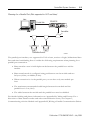
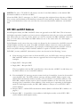
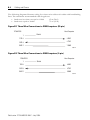
Planning for a Parallel Port (Not supported in V4.2 and later)
Host
Parallel Link
1770-KFC15
ControlNet
ControlNet Devices
31347-M
The parallel port interface, not supported in V4.2 or later, consists of eight, bidirectional data
lines and nine handshaking lines. Consider the following requirements when planning for a
parallel port connection.
• Data transfers occur in half-duplex mode between the parallel host and the
module.
• Data transfer mode is configured using pushbuttons on the module and can
be bytes (8 bits) or nibbles (4 bits).
• When connection is via the parallel port you can have only one module per
host.
• The maximum recommended cable length between the module and the
parallel host is 3 m (10 ft).
• The cable between the module and the parallel host must be shielded.
For detailed cabling and pinout information see Appendix B, Cabling and Pinouts. For a
discussion of data transfer modes and other communication issues, see Chapter 5,
Communicating with the Module and Appendix D, Writing a Parallel Communication Driver.
Publication 1770-UM520C-EN-P - July 2004
1-6
ControlNet System Overview
Notes:
Publication 1770-UM520C-EN-P - July 2004
Chapter
2
Introducing the Module
Overview of the 1770-KFC15 Module
The module enables you to connect RS-232 devices directly to ControlNet. Device types
requiring connection to the ControlNet cable system are varied, including multi-vendor
automation equipment, personal computers, mini-computers, and modems.
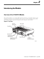
Figure 2.1 Top View
Network
Access Port
Status LEDs
Parallel Port
RS-232C Port
ControlNet Channel B
BNC Connector
ControlNet Channel A
BNC Connector
Fuse
Power Connector
115/230 VAC
Line Selector Switch
31352-M
Publication 1770-UM520C-EN-P - July 2004
2-2
Introducing the Module
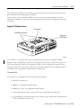
Figure 2.2 Sample Connections
Shielded 8 Conductor Cable
with RJ-45 type connectors
Hand-held
Programming Terminal
1770-KFC15
RS-232-C
PLC-540C15
Portable PC
1770-KFC15
RS-232-C
1770-KFC15
ControlNet
Network B
Sending or Controlling
Devices Supporting PCCC
ControlNet
Network A
RS-232C
Telephone Line
Modem
1770-KFC15
Desktop PC
Parallel
Redundant media
1770-KFC15
31351-M
The module connects to the ControlNet from one (Channel A) or both of its two BNC
connectors via a standard, one-meter, ControlNet coaxial tap. For redundant media, both
connectors are used. See Figure 2.2.
The module has three ports for device connections:
RS-232C serial port—provides half- or full-duplex communication with a serial node such
as a host computer, an intelligent controller or a modem
parallel port—provides half-duplex communication with a parallel host such as a computer
(only in versions prior to V4.2)
network access port—lets you connect a programming terminal or other device to the
module for full network access without disrupting the cable wiring
Publication 1770-UM520C-EN-P - July 2004
Introducing the Module
2-3
The serial and parallel ports use DF1 protocol while the remaining network access
port handles ControlNet packets directly.
Status, Host, and ControlNet LEDs on the top of the module indicate current
operating conditions of the unit and communication activities taking place through
the ports.
Figure 2.3 Bottom View
Pushbuttons
Panel Mounting Holes
7-Segment
LED Displays
31353-M
The module is configured by using the pushbuttons and seven-segment LED
display in the configuration panel on the bottom of the unit as shown in Figure 2.3.
Use the pushbuttons and seven-segment LEDs in the configuration panel on the
bottom of the unit to set and verify the ControlNet address for the module and all
serial RS-232C or parallel communication parameters.
Compatibility
The module is compatible with the following interfaces:
• RS-232C serial ports
• IBM PC-compatible parallel ports
• IBM Type 1 PS/ 2-compatible parallel ports
• ControlNet devices that comply with the ControlNet specification
• programming terminal products that comply with ControlNet specifications
for the Network Access Port
Publication 1770-UM520C-EN-P - July 2004
2-4
Introducing the Module
Notes:
Publication 1770-UM520C-EN-P - July 2004
Chapter
3
Installing the Module
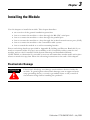
Use this chapter to install the module. This chapter describes:
•
•
•
•
•
•
an overview of the general installation procedure
how to connect the module to a host through the RS-232C serial port
how to connect the module to a host through the parallel port
how to connect the module to a host through the isolated network access port (NAP)
how to connect the module to the ControlNet cable system
how to attach the module to a wall or mounting bracket
Pinout and wiring details are provided in Appendix B, Cabling and Pinouts. Read this if you
need to construct cables. If a tap is not available on the ControlNet cable system for the
module, refer to the ControlNet Cable System Planning and Installation Manual,
CNET-IN002, to determine if your cable system can accommodate another node and to plan
where to mount the tap, then follow the mounting instructions at the end of this chapter.
Electrostatic Damage
ATTENTION
!
Electrostatic discharge can damage semiconductor devices inside the
module. To guard against electrostatic damage wear an approved wrist
strap grounding device, or touch a grounded object to rid yourself of
electrostatic charge before handling the products.
Publication 1770-UM520C-EN-P - July 2004
3-2
Installing the Module
Overview of the Installation Procedure
1. Make sure that the ControlNet cable system can accommodate additional nodes (one
per module being installed).
2. Determine the placement of the module (desk, wall or mounting bracket).
3. Connect the module to the host through either the parallel or serial port, or through
the network access port.
4. Connect the module to a power supply as detailed later in this chapter.
5. Configure the communications parameters on the module as detailed in Chapter 4,
Configuring the Module.
6. Connect the module to the network by using taps.
IMPORTANT
Placement of the module will determine if mounting comes before or
after connecting the cables.
Connecting to a Host through the RS-232C Port
A single, full- or half-duplex, RS-232C serial port using the DF1 protocol provides
communications with either a host computer or intelligent controller. For an explanation of
full- and half-duplex see Chapter 5, Communicating with the Module.
RS- 232C Baud Rates
The module supports the following baud rates: 300, 600, 1200, 2400, 4800, 9600, 19200 and
38400.
Publication 1770-UM520C-EN-P - July 2004
Installing the Module
3-3
Cables
Cabling for the RS-232C connector will vary depending on your application. You can use
either a 3-wire cable or a cable with handshaking lines. For wiring diagrams, see Appendix B,
Cabling and Pinouts. The maximum recommended cable lengths are:
–
–
baud rates less than or equal to 19200
baud rates equal to 38400
15 m (50 ft)
7.5 m (25 ft)
Connector
The RS-232C interface connector at the module end is a DB-25 male connector (DTE) with
EIA (Electronics Industries Association) standard pinout as outlined in Appendix B, Cabling
and Pinouts.
Secure connectors by tightening screwlocks with 3.5 in.-lbs torque until snug.
RS-232C Activity Indicator
The HOST LED will flicker when the module is receiving or transmitting data over the
RS-232C interface. The LED will be off when no data activity is occurring over the RS-232C
interface.
Publication 1770-UM520C-EN-P - July 2004
3-4
Installing the Module
Connecting to a Host through the Parallel Port
IMPORTANT
The parallel port is not supported in V4.2 and later.
The parallel port interface is compatible with the parallel ports of IBM PCs, and also with
bidirectional parallel ports of PS/2 computers. Two data transfer modes are available to
provide compatibility, byte and nibble (4 bit). Specify the mode of parallel port operation
using the push buttons on the configuration panel. Configuration is discussed in Chapter 5,
Communicating with the Module. In either case, the appropriate software driver is required
on the host computer.
Cables
The maximum cable length recommended is 3 m (10 ft). The cable should be shielded.
Connector
The parallel port interface connector is a DB-25 female connector with a standard Centronics
pinout. See Appendix B, Cabling and Pinouts, for cabling and pinout details.
Secure connectors by tightening screwlocks with 3.5 in.-lbs torque until snug.
Parallel Port Activity Indicator
The HOST LED will flicker when the module is receiving or transmitting data over the
parallel interface. The LED will be off when no data activity is occurring over either the
RS-232C or the parallel port interface.
Connecting a Device to the Network Access Port
Use the isolated network access port to connect a transitory device, such as a programming
device, to the module.
Cables
You must use the Allen-Bradley Network Access Cable (catalog no. 1786-CP).
Publication 1770-UM520C-EN-P - July 2004
Installing the Module
3-5
Connecting to the AC Power Supply
The module contains an internal transformer that allows you to switch between 115V ac or
230V ac at 60 Hz or 50 Hz respectively.
ATTENTION
!
WARNING
!
The module does not have an ON/OFF switch so power is applied to the
module as soon as you plug it in. For this reason you must select the
voltage before plugging in the module to prevent damaging the unit.
Ensure that the equipment is connected to a properly grounded AC
115/230V 50/60 Hz supply according to applicable local
requirements and codes.
31355-M
To select the input voltage:
1. Locate the red voltage selector switch on the side of the module beside the fuses.
2. Slide the switch to the left for 115V ac or to the right for 230V ac. The selected
voltage is visible in the indented part of the switch.
3. Plug in the module.
Publication 1770-UM520C-EN-P - July 2004
3-6
Installing the Module
Connecting to the ControlNet Cable System
To connect the module to the ControlNet cable system use an approved ControlNet tap.
Refer to the ControlNet Cable System Planning and Installation Manual, CNET-IN002, for
complete instructions on connecting the tap to the cable system.
ATTENTION
!
If the module is connected to a cable system that does not support
redundant media, the tap dropline should be connected to the BNC
connector labeled channel A. The channel B connector should be unused.
If the cable system is redundant, the module should be connected such
that all devices on the network use the same cable for the same channel.
The channel A connector on all products should be connected to the
same cable. The same applies for the channel B connectors.
To connect the module to the tap do the following:
1. If the module is not the last device in the segment:
– Connect the tap to the coaxial trunkline.
– Connect the dropline BNC to the channel A BNC of the module.
2. If the module is the last device in the segment, install a terminator at the end of the
cable segment, then follow the instructions in step 1.
3. If using redundant media, repeat either step 1 or step 2 for channel B of the module.
Publication 1770-UM520C-EN-P - July 2004
Installing the Module
3-7
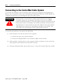
Attaching the Module to a Wall or Mounting Bracket
You can set the module on any flat surface, such as a desk or shelf, or attach it to a mounting
bracket or directly to a wall for vertical placement. Use the two #10-32 threaded inserts on
the unit if you are mounting it vertically. Maintain a 1” clearance on all sides of the module.
150 mm
5.9 inches
DIA.
5.16 - 5.54 mm
0.203 - 0.218 inches
31357-M
To attach the module to a wall:
1. Mark the position of the screw inserts on the surface to which it is to be attached.
2. Drill holes through the surface, as shown in the drawing above.
3. Insert screws from the back of the surface, through the holes and into the screw
inserts, then tighten.
IMPORTANT
The configuration pushbuttons and displays will not be accessible or
visible if the module is wall or bracket mounted.
Publication 1770-UM520C-EN-P - July 2004
3-8
Installing the Module
Notes:
Publication 1770-UM520C-EN-P - July 2004
Chapter
4
Configuring the Module
Use this chapter to configure the module’s communication parameters via the pushbuttons
and seven-segment displays in the configuration panel on the bottom of the module.
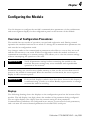
Overview of Configuration Procedures
The module has two modes of operation, run mode and configuration mode. During normal
operation the module functions in run mode. To change the communication parameters the
unit must be in configuration mode.
Any changes made to the communication parameters take effect as soon as they are saved
and the unit returns to run mode. While in configuration mode the module continues to
communicate according to its current settings. This allows you to view the current settings
without interrupting the operation of the unit.
IMPORTANT
Verify all parameter settings before connecting the module to the
network. Incorrect settings may cause unreliable and unpredictable
operation of the network.
Parameter settings are saved in non-volatile memory so that you do not lose them even if
power to the module is interrupted. When the module is in run mode, the seven-segment
display is off to conserve power.
IMPORTANT
If the module displays symbols other than those shown in this chapter, it
is malfunctioning. Contact your Allen-Bradley representative to arrange
to return the unit for servicing.
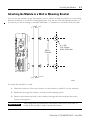
Displays
The following drawing shows the displays on the configuration panel on the bottom of the
module. The left display (one digit) shows the number of the parameter being configured.
The two right displays (two digits) show the current setting for that parameter.
Communication parameters are configured in two menus, a main menu for basic parameters,
and a sub-menu for more advanced parameters for the RS-232C serial port.
Publication 1770-UM520C-EN-P - July 2004
4-2
Configuring the Module
Parameter Number
Current Setting
VIEW
SAVE
DATA
EXIT
31358-M
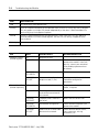
Pushbuttons
The operation of the three pushbuttons labelled VIEW, DATA, and EXIT in the
configuration panel are described in this table.
Pressing this button or button
combination:
Performs this task:
VIEW
In run mode, places the module in configuration mode. This is the only
button that has a function in run mode.
In configuration mode, cycles through the possible communication
parameters (displayed on the left digit).
If you hold the button down for more than 1 second, the parameter
number advances automatically.
DATA
In configuration mode, cycles through the possible communication
settings for the parameter shown on the left. The data is displayed on
the right two digits. If you hold the button down for more than 1 second,
the settings advance and accelerate automatically. When the left
display shows A, C, or P, press DATA to enter the sub-menu.
Publication 1770-UM520C-EN-P - July 2004
Configuring the Module
4-3
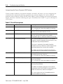
Pressing this button or button
combination:
Performs this task:
EXIT
In configuration mode at the main menu, returns the module to run
mode without saving any changes. From the sub_menu, returns to the
main menu.
VIEW + EXIT
In configuration mode, saves all configuration changes, and returns
the module to run mode from either menu. The module will begin
operating with the new configuration as soon as it returns to run mode.
VIEW + DATA
In configuration mode, resets all communication parameters to their
factory defaults. The changes do not take effect until the configuration
is saved, and the module returns to run mode, i.e., until VIEW and EXIT
are pressed simultaneously. If only EXIT is pressed the unit returns to
run mode without making the factory default changes.
Configuring the Module by Using Pushbuttons
Before configuring the module, you should determine the parameter settings the network
requires. If they differ from the factory defaults shown in the parameter tables on the
following pages, use the directions below to change them.
For normal operation, you must configure the basic communication parameters. For special
communication needs you can configure the advanced communication parameters, which
provide more flexibility in the operation of the module.
While you are changing the parameters in configuration mode, the module continues to
operate using its current settings. The changed parameter settings do not take effect until they
are saved and the module returns to run mode.
Viewing Basic Parameter Settings
To view the current parameter settings:
1. Press the VIEW button to enter configuration mode. The first parameter number is
displayed on the left display, with its current setting in the right two displays.
2. Press VIEW to display the next parameter and its current setting, or hold it down to
cycle through the communication parameters. When the last parameter is reached, the
configuration number wraps back to the start.
3. Press EXIT to return the module to run mode without changing parameters.
Publication 1770-UM520C-EN-P - July 2004
4-4
Configuring the Module
Configuring the Basic Parameters
The basic parameters are numbered zero to eight. The letters A, C, F, and P also come up on
the seven-segment LEDs as you cycle through them as described above. The letter A lets you
into the sub-menu that contains the advanced communication parameters. The settings
displayed beside letter F are the series and revision number of the module.
To configure the basic parameters:
1. Press the VIEW button to enter configuration mode.
2. Press VIEW as often as necessary or hold it down until the desired parameter is
reached.
3. Once the desired parameter is displayed, press the DATA button to cycle through the
available settings. Only valid selections for the given parameter option are displayed.
4. When you have reached the desired data setting, you can press VIEW to display the
next parameter.
5. When all relevant parameters have been set, press VIEW and EXIT together to save
the parameter settings and return the module to run mode.
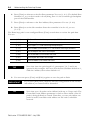
The basic communication parameters and their valid settings are described in Table 4.1.
Table 4.1 Basic Communication Parameters
Parameter Number
Parameter
Description
Factory
Default
Network Address
Auto Addressing (AA) or 01-99
AA or 99
ControlNet
Auto Addressing is not supported in
version 4.2 or later. The factory default
for V4.2 is 99.
Port
DF1 Port
Serial (00), Parallel (01)
Parallel port is not supported in version
4.2 or later.
Publication 1770-UM520C-EN-P - July 2004
00
Configuring the Module
4-5
Table 4.1 Basic Communication Parameters
Parameter Number
Parameter
Description
Factory
Default
Baud Rate
300 (03), 600 (06), 1200 (12), 2400 (24),
4800 (48), 9600 (96), 19200 (19), 38400
(38) bits/sec
96
Parity
None (00), Even (01), Odd (02)
00
Full/Half Duplex
Full duplex (00), Half duplex (01) for
serial port only
00
Parallel Port Transfer
Nibble data transfers to host (01), Byte
data transfers to host (02)
01
RS-232C
Parallel
Parallel port is not supported in version
4.2 or later.
DF1
Error Detection
BCC Block Check Code (00), or CRC16
Cyclic Redundancy Check (01)
00 or 01
For V4.2 and later, the default is CRC
(01).
Publication 1770-UM520C-EN-P - July 2004
4-6
Configuring the Module
Table 4.1 Basic Communication Parameters
Parameter Number
Parameter
Description
Factory
Default
DF1 Station Address
The station address of this node on the
DF1 link.
00
Valid addresses are 00-77 Octal
inclusive.
Diagnostic Command
Execution
Determines whether PCCC diagnostic
commands are executed directly by the
KFC15 (01) or passed through to the host
computer (00).
01
Advanced Parameters
Sub-menu
Lets user into the sub-menu to set extra
parameters.
N/A
Other
Press DATA key to enter the Advanced
Parameters sub-menu.
Firmware Revision
(major, minor)
Displays the module series and revision.
V4.2 and later displays the revision as
numbers, e.g., 4.2. Older revisions
display this as letters, e.g., B B.
Publication 1770-UM520C-EN-P - July 2004
N/A
Configuring the Module
4-7
Table 4.1 Basic Communication Parameters
Parameter Number
Parameter
Description
Factory
Default
Displays diagnostic counter information.
N/A
V4.2 and later support additional parameters.
Counter Sub-menu
Press the DATA key to enter the
Counters sub-menu.
See the new counter table in Appendix
C.
Extra Path Sub-menu
Lets the user into the Extra Path
sub-menu.
N/A
Press the DATA key to enter the Extra
Path sub-menu.
See the Extra-hop section in chapter 5.
NOTE: Network paths are made up of
hops.
Publication 1770-UM520C-EN-P - July 2004
4-8
Configuring the Module
Configuring the Advanced Communication Parameters
The advanced communication parameters, numbers zero through nine, are in the advanced
parameters sub-menu. See Table 4.2 on page 4-9. Sub-menu parameters are followed by a
decimal in the display. View them the same way basic parameters are viewed, when you enter
the sub-menu.
Advancead Parameter Number
Current Setting
Sub-Menu Indicator
VIEW
SAVE
DATA
EXIT
31359-M
1. To enter the sub-menu, press VIEW until parameter A appears in the left display and
dashes in the right display, then press DATA.
The number on the left changes from A to 0, and its decimal point lights up,
remaining lit as long as you are in the sub-menu.
2. Press VIEW to display the sub-menu parameters, as described for the basic
parameters, until you reach one you want to configure.
3. Press DATA to display and cycle through the settings for the advanced parameters
until you get to the one you want.
4. Repeat the process until you have completed setting the parameters.
5. Press VIEW and EXIT while in the sub-menu to save the changes and return the
module to run mode.
Publication 1770-UM520C-EN-P - July 2004
Configuring the Module
4-9
Note: You can press EXIT to return to the main menu from the sub-menu, if
necessary. This does not end the configuration session. You can go back to the
sub-menu as described in step 1. The changes you have made to advanced parameters
are not lost as long as you go through the save and exit procedure, described on
page 4-12, when you return the module to run mode.
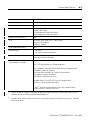
Table 4.2 Advanced Communication Parameters
Parameter Number
Parameter
Description
Factory
Default
Number of Retries
Number of allowable retries per attempt
on the RS-232C link: 00 - 10
02
Duplicate Message
Detection
Disabled (00), Enabled (01). If enabled,
the module will acknowledge and
discard duplicate messages received on
the DF1 link.
01
DF1 ACK Time-out
The time to wait for an ACK from the
host computer. The time is from 0.1 to 5
seconds in 0.1 second increments
(01-50). To calculate the time-out,
multiply the number in the display by 0.1
second.
10
Modem Handshaking
Disabled (00), Enabled (01)
00
Publication 1770-UM520C-EN-P - July 2004
4-10
Configuring the Module
Table 4.2 Advanced Communication Parameters
Parameter Number
Parameter
Description
Factory
Default
CTS to Transmit Delay
The delay between the CTS signal and
the start of transmission. The delay is
from 0 to 0.99 seconds in 10 ms (0.01
second) increments.
No delay
(00)
To calculate the delay, multiply the
number in the display by 0.01 seconds.
This parameter takes effect only when
the KFC15 is in half-duplex mode and
handshaking is enabled.
End of Message to RTS
Off
The delay between the end of a message
and the KFC15 setting RTS inactive. The
delay is from 0 to 0.99 seconds in 10 ms
(0.01 second) increments.
No delay
(00)
To calculate the delay, multiply the
number in the display by 0.01 seconds.
This parameter takes effect only when
the KFC15 is in halfduplex mode and
handshaking is enabled.
Embedded Response
Mode
configure the embedded response mode
• 0 – Auto Detect – Default
• 1 – Always send embedded
responses
• 2 – Never send embedded
responses
Publication 1770-UM520C-EN-P - July 2004
0
Configuring the Module
4-11
Table 4.2 Advanced Communication Parameters
Parameter Number
Parameter
Description
Factory
Default
Message Reply
Time-out
Used to configure the message reply
time-out.
5 secs
This parameter represents time in
seconds and has a range of 1 to 99
seconds. The default value is 5 seconds.
Default DF1 Address
Used to configure the default DF1
address.
FE
This parameter is a hexadecimal value
and has a range of 0 to FF. The value FE
is a special value that indicates that the
current ControlNet address should be
used. The default value is FE. Therefore,
the default behavior is to use the
ControlNet address just as the old KFC
did.
Auto Recovery
Used to configure the auto-recovery
feature.
0
A parameter value of 0 means disabled
(the default), and a value of 1 means
enabled.
Publication 1770-UM520C-EN-P - July 2004
4-12
Configuring the Module
Saving Configuration Changes
To save all parameters in both the main menu and the sub-menu in non-volatile memory,
press the VIEW and EXIT buttons simultaneously. The module returns to run mode. This
ends the configuration session.
If the save is successful, the display will show three dashes for a period of two seconds.
When the module returns to run mode, the new configuration takes effect and the display
turns off. While most parameters take effect immediately, some, e.g., the ControlNet MAC
ID, initiate a reset of the module. After the module resets, the new parameters take effect.
VIEW
SAVE
DATA
EXIT
31360-M
If the save is not successful, the module is malfunctioning. The left display will show
hardware fault number 6 and the STATUS LED will show solid red. If this happens, contact
your Allen-Bradley representative.
VIEW
SAVE
DATA
EXIT
31361-M
Publication 1770-UM520C-EN-P - July 2004
Configuring the Module
4-13
Exit Without Saving
To exit without saving while in the main menu, press EXIT. The module returns to run mode
from configuration mode without saving any changes. This ends the configuration session
and the previous settings will remain in effect.
To return to the main menu from the sub-menu, press EXIT. You can move between the
two menus as much as you need to during any given configuration session.
If you exit from the main menu without saving, as described above, any changes made in the
sub-menu are not saved. If you save and exit from the main menu, changes made in the
sub-menu are saved as well.
IMPORTANT
If the module is left inactive (i.e., with no buttons pressed) in
configuration mode for 3 minutes, it returns to run mode. Any changes
made since going into configuration mode will not be saved. Also, if
power to the unit is interrupted while in configuration mode, any
changes made will not be saved.
Setting Factory Defaults
To reset all parameters in both menus to their factory defaults, press the VIEW and DATA
buttons simultaneously when in configuration mode. When this button combination is
pressed, the module displays the first parameter and its factory default.
To save the factory default parameters, press the VIEW and EXIT buttons simultaneously.
If you press only the EXIT button, the unit returns to run mode without changing the
parameters to their factory defaults.
Verifying the Communication Parameters
Before connecting the module to the network, cycle through the parameter settings and verify
that they are correct. Incorrect settings may cause unreliable and unpredictable operation of
the network.
Publication 1770-UM520C-EN-P - July 2004
4-14
Configuring the Module
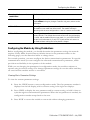
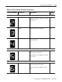
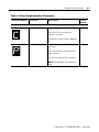
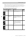
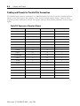
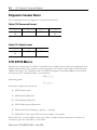
1770-KFC15 Diagnostic Counters
Diagnostic counters can now be accessed on the 7-segment display of the new 1770-KFC15
module. All of the counters, except 0, are 16 bits wide and are displayed in hexadecimal
format. Press the [Data] key to toggle between viewing the low byte and high byte. See
Table C.6 on page C-4 for a list of counters.
Counter 0 is not really a counter at all; rather it displays the value of the hardware handshake
lines.
To view the counters:
1. Press the [View] key until you see a C and 2 dashes {C - -}.
2. Press the [Data] key to enter the counters submenu. Counter 0, the hardware
handshake lines, is displayed.
3. Press the [View] key to advance to counter 1. The low byte of Counter 1, the number
of DF1 packets sent, is displayed. For example, if 36 packets (24 hexadecimal) have
been transmitted, you will see {1. 2 4.}. Notice the decimal points after the 1 and after
the 24. The decimal point after the 1 indicates that you are in a submenu. The decimal
point after the 24 indicates that the low byte is being displayed.
4. Press the [Data] key to view the high byte of the counter. You see {0. 0 0}. There is
no decimal point after the 00, indicating that this is the high byte.
5. Press the [Data] key again to view the low byte.
6. Press the [View] key to display the next counter.
7. Press the [View] and [Data] keys together to clear all the counters.
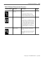
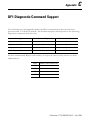
Reading 1770-KFC15 Counters With a Diagnostic Command
Diagnostic counters can be read by sending a PCCC Diagnostic Read Counters command to
the 1770-KFC15 module. See page C-2. The only change for firmware version 4.2 is that the
new set of counters listed in Table C.6 on page C-4 can now be read by setting the address
parameter to 0x0001. If the address parameter is set to any other value, the old 1770-KFC15
counters will be read instead.
Note that the PCCC diagnostic command can be sent from DF1 or ControlNet. On
ControlNet, the command should be sent to the PCCC object.
Publication 1770-UM520C-EN-P - July 2004
Chapter
5
Understanding the Extra-hop Feature
The extra-hop feature has been added so that network routing information can be added to
standard PCCC, DF1 packets. For example, using this feature, a PCCC message from a
PLC-5 message instruction can be routed through a 1770-KFC15 module to a 1756-CNB
module, out the ControlLogix backplane port of the 1756-CNB module, and across the
ControlLogix backplane to a Logix controller.
TIP
A hop is the route a message takes to get from one module to the
next, via a single network segment. Network routing paths are
constructed of one or more hops.
Before you send a PCCC read or write command to a Logix controller, you need to map one
or more of the Logix controllers tags to a PLC- or SLC-style file number. To map a tag in
RSLogix 5000:
1. Ensure RSLogix 5000 is offline.
2. Select the Logic menu.
3. Select Map PLC/SLC Messages.
4. Map one or more tags to file numbers.
5. Download the new configuration to the Logix controller.
There are two ways to use the extra-hop feature:
• Method 1: No Configuration
• Method 2: Configure a Path Using the Pushbuttons and 7-segment Display
Publication 1770-UM520C-EN-P - July 2004
5-2
Understanding the Extra-hop Feature
Method 1: No Configuration
This is specifically intended to route messages through CNB modules to Logix controllers in
the same backplane. Just add 100, 150, or 200 to the ControlNet node address of the DF1
message. (In full-duplex mode, the ControlNet node address of the DF1 message is simply
the DF1 destination address which is ignored on the local DF1 link. In-half duplex mode, it is
the remote address.)
When the new KFC sees an address that is higher than 99, it will add a Port Number of 1 and
a Slot/Address of 0, 1 or 2 to the message. The Port Number of 1 refers to the ControlLogix
backplane port of the CNB module.
• Adding 100 to the ControlNet node address will route the message to slot 0.
• Adding 150 to the ControlNet node address will route the message to slot 1.
• Adding 200 to the ControlNet node address will route the message to slot 2.
IMPORTANT
EXAMPLE
The actual ControlNet address of the CNB must be between 1 and 50.
You have a Logix rack with a controller in slot 0. The rack also contains
a CNB that is set to Mac ID 5. You set up a PLC-5 (or other DF1 device)
to send a message to address 105 (decimal). The message will get routed
to the CNB at Mac ID 5 and then to the controller in slot 0.
Publication 1770-UM520C-EN-P - July 2004
Understanding the Extra-hop Feature
5-3
Method 2: Configure a Path Using the Pushbuttons and
7-segment Display
TIP
This method works only for the 1770-KFC15 module.
For the 1747-KFC15 module, use method 1.
You can use this method to access Logix controllers that are in slots greater than 2. As many
as 99 paths can be defined, with as many as 3 hops each. The ControlNet node address
parameter is used to select which of the 99 paths is being defined or viewed. Therefore, you
can define only one path for each ControlNet node address on the local ControlNet network.
A path consists of a path length followed by a sequence of port numbers and network
addresses or slot numbers.
Path Length
The path length can be set to 0, 2, 4, or 6.
0 – Indicates that no path is configured.
2 – The path contains 1 hop (1 Port and 1 Address/Slot Number).
4 – The path contains 2 hops.
6 – The path contains 3 hops.
Publication 1770-UM520C-EN-P - July 2004
5-4
Understanding the Extra-hop Feature
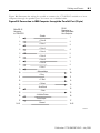
Port Numbers
Port numbers can range from 1 to 14. If a device has a backplane connector, that connector
will be port 1.
See Table 5.1 on page 5-4 for the port numbers for several modules. Check the product
documentation or EDS file to find the port numbers of other modules.
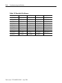
Table 5.1 Port numbers
Module:
Port Number:
Description
1756-CNB
1756-CNBR
Port 1
ControlLogix Backplane
Port 2
ControlNet
1788-CN2DN
Port 2
DeviceNet
Port 3
ControlNet
Port 2
ControlNet
Port 3
DF1
1770-KFC15
1747-KFC15
Publication 1770-UM520C-EN-P - July 2004
Understanding the Extra-hop Feature
5-5
Address/Slot Number
This is either the address of a node on a network or a slot number of a module in a backplane.
The value has a range of 0 through 99. On the ControlLogix backplane, you can use slot
numbers of 0 through 16.
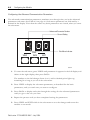
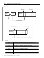
Example 5.1
EXAMPLE
This example assumes a 1756-CNB at ControlNet node address 54 and a
Logix controller (LGX) in slot 12 of a ControlLogix backplane. The slot
number of the 1756-CNB, as well as the ControlNet node address of the
1770-KFC15, are not specified, since they are not needed to construct
the path.
CNB at node address 54
DF1
device
KFC
module
LGX in slot 12
ControlLogix
backplane
RS-232
ControlNet network
To program the path:
1. Press the [View] key several times until the path sub-menu appears.You see {P - -}.
2. Press [Data] to enter the path sub-menu.
3. Press [Data] to select the address of the ControlNet device (e.g., the CNB). If the
address is 54, you see {-. 5 4}. The leading - indicates that no path has been defined
for this ControlNet node address. That is, the path length is 0. If the path length is
non-zero, you will see an A instead of the -; for example, {A. 5 4}. The A stands for
Address or Active.
4. Press [View] to advance to the Path Length parameter. You see {L. 0 0}
5. Press [Data] to set the Path Length. Our example has 1 hop, so the path length will be
2, since 2 bytes are needed (one for Port and one for Slot/Address). You see {L. 0 2}.
Publication 1770-UM520C-EN-P - July 2004
5-6
Understanding the Extra-hop Feature
6. Press [View] to advance to the first Port parameter. You see {1. 0 1}. The default Port
Number is 1, so you don’t need to do anything. Port 1 is the ControlLogix backplane
port of the CNB module.
7. Press [View] to advance to the first Address/Slot parameter. You see {2. 0 0}
8. Press [Data] to set the Slot number. Since the controller is in slot 12, you see
{2. 1 2}.
The Extra-hop path is now configured.Press [View] several times to review the path data.
You see:
{A. 5 4}
The ControlNet node address parameter (the CNB ControlNet node address)
{L. 0 2}
The Path Length
{1. 0 1}
The first port. (1 => CNB ControlLogix backplane port).
{2. 1 2}
The first Address/Slot number (12 => Slot number of the Logix Controller).
{3. 0 1}
The second port. Not used in our example.
{4. 0 0}
The second Address/Slot number. Not used.
{5. 0 1}
The third port. Not used in our example.
{6. 0 0}
The third Address/Slot number. Not used.
TIP
Note that since the path length is 2, parameters 3, 4, 5 and 6 are
ignored in this example. Also note that the Port Numbers default to 1,
while the Address/Slot values default to 0.
9. You can now press [View] and [Exit] together to save the path to flash.
IMPORTANT
TIP
If you press [Exit] twice, the KFC will exit configuration mode and any
information you entered will be discarded.
Note that up to 99 paths can be defined, with up to 3 hops each. The
ControlNet node address parameter is used to select which of the 99
paths is being defined or viewed. Therefore, you can only define one
path for each ControlNet node address on the local ControlNet
network.
Publication 1770-UM520C-EN-P - July 2004
Understanding the Extra-hop Feature
5-7
Example 5.2
EXAMPLE
For this example you have 2 ControlNet networks. (See the diagram that
follows). The first contains the 1770-KFC15 and a 1756-CNB. The
1756-CNB is at ControlNet node address 65. This is CNB 1. CNB 1 is in
slot 4 of ControlLogix backplane 1.
The second network contains 2 1756-CNB modules. One CNB is at
ControlNet node address 1 (CNB 2) and the other is at ControlNet node
address 53 (CNB 3). CNB 2 is in slot 7 of ControlLogix backplane 1.
CNB 3 is in ControlLogix backplane 2 along with a Logix Controller
(LGX) in slot 16.
Note that neither the slot numbers of CNB 1 and CNB3 nor the node
address of CNB 2 are needed to construct the path.
The following path will route a DF1 message from the DF1 device to the Logix Controller
in slot 16 of the remote ControlLogix backplane. The DF1 message should be sent to
address 65.
Publication 1770-UM520C-EN-P - July 2004
5-8
Understanding the Extra-hop Feature
Figure 5.1
CNB 1 (slot 4, node
address 65)
KFC
module
DF1
device
CNB 2 (slot 7,
node address 1)
ControlLogix
backplane 1
RS-232
ControlNet network 1
CNB 3 (node address 53)
LGX (slot 16)
ControlLogix
backplane 2
ControlNet network 2
You see:
{A. 6 5}
The ControlNet node address parameter (node address of CNB 1)
{L. 0 6}
The Path Length (6 => 3 hops)
{1. 0 1}
The 1st port. (1 => ControlLogix Backplane port of CNB 1)
{2. 0 7}
The 1st Address/Slot Number. (7 = > Slot # of CNB 2)
{3. 0 2}
The 2nd port. (2 => ControlNet port of CNB 2)
{4. 5 3}
The 2nd Address/Slot Number. (53 => The ControlNet node address of CNB 3)
{5. 0 1}
The 3rd port. (1 => ControlLogix Backplane port of CNB 3).
{6. 1 6}
The 3rd Address/Slot Number. (16 => Slot # of Logix Controller.)
Publication 1770-UM520C-EN-P - July 2004
Chapter
6
Communicating with the Module
DF1 Communication
The module supports both full-duplex and half-duplex DF1 protocol between it and a host
device. This protocol can be used over either the serial or parallel interface to send PCCC or
ControlNet messages across the ControlNet cable system to other nodes. For more
information on PCCC messages refer to the DF1 Protocol and Command Set Reference
Manual, 1770-RM516.
The host device must send messages in a form that the end node it is communicating with
understands. The module does not translate between two types of messages. If the end node
only recognizes one type, the host device’s communication driver must send the same form.
Publication 1770-UM520C-EN-P - July 2004
6-2
Communicating with the Module
Serial Communication
Serial communication with the module can be either full- or half-duplex DF1. The duplex
used depends on the overall application’s requirements.
Full-duplex serial protocol:
• is a direct link that allows simultaneous two-way transmission
• often requires a system programmer to use interrupts and multi-tasking techniques
• is intended for high-performance applications where maximum data throughput is
necessary
• gives faster data throughput than half duplex, but is more difficult to expand or to use
when communicating with more than one 1770-KFC15 module
• Since it is faster and easier to configure, full-duplex mode is always recommended
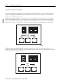
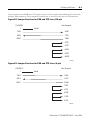
Figure 6.1 Full-duplex Serial Protocol
Programmable
Controller or
Host Computer
Full duplex serial protocol
KFC15
T
T
N
T
T
N
N
ControlNet
Nodes
31362-M
Publication 1770-UM520C-EN-P - July 2004
Communicating with the Module
6-3
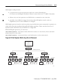
Half-duplex serial protocol:
• is a protocol for one host processor and one or more field devices.
You must use half-duplex modems if there is more than one 1770-KFC15 module.
• allows only one host processor or field device to transmit at any one time
• provides a less effective usage of resources than full duplex; may be easier to
implement, but it is more difficult to configure
Half-duplex protocol can be used on a point-to-point link, but more commonly it operates on
a link with all nodes interfaced through half-duplex modems. There can be from 0 to 63
decimal nodes simultaneously connected to a single link.
With half-duplex protocol, you can use a:
two-circuit system— the master sends and slaves receive on one circuit, slaves send and
master receives on the other
one-circuit system— master and slaves send and receive on the same circuit
Figure 6.2 Half-duplex Multi-drop Serial Network
PLC Computer
or
Other Hosts
Modem
Multidrop Network
Modem
Modem
RS-232C Link
Modem
RS-232C Link
KFC15
KFC15
ControlNet
T
T
N
Nodes
RS-232C Link
KFC15
ControlNet
T
T
T
N
N
N
T
Nodes
ControlNet
T
T
T
N
N
N
T
T
T
N
N
Nodes
31363-M
Publication 1770-UM520C-EN-P - July 2004
6-4
Communicating with the Module
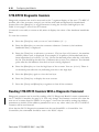
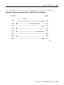
Parallel Communication
Parallel communication with the module can be half-duplex DF1 only. Full duplex is not
supported. The parallel port is not supported in V4.2 or later.
Half-duplex parallel protocol:
• uses the same protocol as with half-duplex RS-232C (serial)
• must be point-to-point (cannot be multidrop)
Computer or
Other Host
Parallel Link
KFC15
T
T
N
T
T
N
N
ControlNet
Nodes
31364-M
With parallel half-duplex communication, a host device can send eight bits of the DF1
message at a time to the module. The host device can receive four bits of a message at a time
from the module in NIBBLE MODE. In instances where the host device has a bidirectional
parallel port, it can receive messages eight bits (one byte) at a time in BYTE MODE. See
chapter 4, Configuring the Module, for instructions on setting the operating mode.
If you plan to use parallel port communication and your application requires that you write
your own driver, see appendix D, Writing a Parallel Communication Driver, for details.
Publication 1770-UM520C-EN-P - July 2004
Communicating with the Module
6-5
Embedded Responses
An embedded response occurs when a DF1 ACK or NAK is embedded within another DF1
message. Embedded responses can improve the throughput of a full-duplex DF1 link since a
transmitter will not need to wait any longer than necessary to receive a response (ACK or
NAK) to the last message it has sent. The old KFC would always send an embedded response
whenever there was an opportunity to do so. However, some DF1 drivers can not tolerate
them. Therefore, the new KFC (V4.2 and newer) can be configured to send or not send
embedded responses.
By default, the 1770-KFC15 will wait until it hears an embedded response before sending
one. This is referred to as embedded-response “auto-detect” mode.
NOTE: This is the only embedded-response mode available on the 1747-KFC15.
The 1770-KFC15 defaults to embedded response “auto-detect” mode but can also be
configured to always send or never send embedded responses. Parameter 6 in the ‘A’
sub-menu is used to configure the embedded response mode. The parameter can have one of
the following values:
• 0 – Auto Detect – Default
• 1 – Always send embedded responses
• 2 – Never send embedded responses
To configure this parameter, do the following:
1. Press the [View] key several times until the ‘A’ sub-menu appears. You see
{A - -}
2. Press the [Data] key to enter the sub-menu.
3. You see {0. 0 2} assuming the number of DF1 retries is set to 2.
4. Press the [View] key several times until parameter 6 appears. You see
{6 0 0}, indicating that Auto-Detect mode is active.
5. Press the [Data] key to change the value.
6. Press the [View] and [Exit] keys together to save the new value.
For more information on configuring 1770-KFC15 parameters, refer to chapter 4.
Publication 1770-UM520C-EN-P - July 2004
6-6
Communicating with the Module
Message Reply Time-out
To aid in memory buffer management, a message reply time-out parameter has been added to
the V4.2 and later 1770-KFC15 firmware. This is the length of time the KFC will wait for a
reply to a request message. Note that this is different than an ACK time-out, which occurs if
the network node to which the message was sent cannot respond. The message reply time-out
becomes active only after an ACK is received.
If the request message was sent on ControlNet and no reply message is received before the
timer expires, an error reply with the status byte set to 2 (2 means undeliverable) is sent on
DF1 and the memory buffers are freed up to handle new messages.
If the request message was sent on DF1 and no message is received before the timer expires,
no error reply is sent on ControlNet. However, the memory buffers are freed up to handle
new messages. It is assumed that the node that originated the original request message on
ControlNet has already timed out and does not need a reply.
For the 1770-KFC15, parameter 7 in the ‘A’ sub-menu is used to configure the message reply
time-out. This parameter represents time in seconds and has a range of 1 to 99 seconds. The
default value is 5 seconds. For instructions on how to program a parameter in the ‘A’
sub-menu, refer to chapter 4.
NOTE: For the 1747-KFC15, the message reply time-out is set to 10 times the DF1 ACK
time-out. The default value is 32 seconds since the default DF1 ACK time-out value is 3.2
seconds.
TIP
In a normally functioning system, the message reply timeout should
never occur, since it would be rare for a device to acknowledge a
message with an ACK and then never send a reply.
Default DF1 Address
When a standard (non-DH+) PCCC message is received from ControlNet, the KFC must
decide to which destination address to send it on the DF1 link. The old KFC would always
send such packets with a DF1 destination address equal to the ControlNet address of the
KFC. This means that if you are using half-duplex mode, the address of the other DF1 device
must be set to the ControlNet address of the KFC. For the new 1770-KFC15, the default
DF1 destination address can be configured so that the DF1 address of the other device does
not have to match the ControlNet address of the KFC.
For the 1770-KFC15, parameter 8 in the ‘A’ sub-menu is used to configure the default DF1
address. This parameter is a hexadecimal value and has a range of 0 to FF. The value FE is a
special value that indicates that the current ControlNet address should be used. The default
value is FE. Therefore, the default behavior is to use the ControlNet address just as the old
KFC did. For instructions on how to program a parameter in the ‘A’ sub-menu, refer to
chapter 4.
Publication 1770-UM520C-EN-P - July 2004
Communicating with the Module
6-7
NOTE: The new 1747-KFC15 will always use the ControlNet address as the default DF1
destination address as did the old KFC.
Note that DH+ PCCC messages (i.e., PCCC messages that originate from a device on DH+)
have source and destination information contained in their message header. Therefore, these
source and destination values are used for the source and destination addresses on the DF1
link.
DF1 SRC and DST Address
In full-duplex mode, the SRC and DST values are ignored on the DF1 link. This is because
full-duplex operation implies a point-to-point configuration with only two nodes on the DF1
link. Since there are only two nodes, there is no need to examine the SRC and DST values. In
fact, you will often see the SRC and DST addresses set to the same value on a full-duplex
DF1 network.
In half-duplex mode, more than two nodes are allowed to be connected to the DF1 network
(if half-duplex modems are used). The SRC and DST address values are used to determine
which node is to receive which packet. For example, in half-duplex mode, the KFC will not
receive any DF1 messages unless the DST address is equal to its DF1 station address.
DF1 SRC (source) and DST (destination) values are chosen in the following 3 cases:
1. If the message request came in from the DF1 port, the DF1 reply message will have
SRC and DST address values that are opposite that of the request message. For
example:
• Reply DST = Request SRC
• Reply SRC = Request DST
This is compliant with the DF1 specification. Note that the old KFC would always set
the DST address to its ControlNet address.
2. If a standard PCCC message request comes in from ControlNet, it must be forwarded
onto the DF1 link. The DF1 request message will have a DST address equal to the
default DF1 destination address (usually set to the KFC’s ControlNet address). The
DF1 SRC address will be equal to the ControlNet address of the node that sent the
message (the ControlNet source address) if the serial port is operating in full-duplex
mode. In half-duplex mode, the DF1 SRC address is always set to the KFC’s DF1
station address.
• Request DST = default DF1 destination address (Refer to Default DF1 Address on
page 6.)
• Request SRC = ControlNet source address (full-duplex mode) or the KFC’s DF1
station address (half-duplex mode).
Publication 1770-UM520C-EN-P - July 2004
6-8
Communicating with the Module
3. If a DH+ PCCC message request comes in from ControlNet, it must be forwarded
onto the DF1 link. Since DH+ PCCC messages have source and destination
information contained in their message header, these source and destination values
can be used for the SRC and DST addresses on the DF1 link. However, note that in
half-duplex mode, the DF1 SRC address is always set to the KFC’s DF1 station
address.
• Request DST = Destination address from message header
• Request SRC = Source address from message header (full-duplex mode) or the KFC’s
DF1 station address (half-duplex mode).
TIP
Since it is easier to configure and much faster to run, full-duplex mode
is always the preferred mode of operation. Use half-duplex mode only
if you do not have a choice.
RSLinx DF1 Driver Anomaly
In versions of RSLinx older than 2.31.00, the DF1 driver has a rare anomaly which causes the
driver to cease to transmit packets. If the driver is in this state and you examine the RSLinx
driver diagnostics for the DF1 driver, you will see the Write Errors counter incrementing as
the driver attempts to send packets.
To recover from this condition, either stop and start the driver in RSLinx or delete it and
configure it again.
Publication 1770-UM520C-EN-P - July 2004
Communicating with the Module
6-9
Auto-recovery
An auto-recovery feature has been added so that the new KFC can automatically recover
from non-hardware error conditions. The default setting for this feature is “Disabled.” It is
recommended that this feature be enabled if the KFC is operating in a remote location where
a manual reset of the module would be difficult. Using the KFC to connect to a remote
location using phone modems is one example.
One example of a non-hardware error condition that could trigger this feature would be that
the KFC ran out of memory buffers and was unable to recover from this condition within 35
seconds.
For the 1770-KFC15, parameter 9 in the ‘A’ sub-menu is used to configure the auto-recovery
feature. A parameter value of 0 means disabled (the default), and a value of 1 means enabled.
For instructions on how to program a parameter in the ‘A’ sub-menu, refer to chapter 4.
NOTE: For the 1747-KFC15, switch 7 of DIP switch bank S1 is used to configure the
auto-recovery feature. Off means disabled (the default), and on means enabled.
Message Buffers
The new 1770-KFC15 has 18 message buffers. However, if the messages are PCCC messages
coming in from ControlNet, the number is limited to 10 outstanding messages.
From an application point of view, this means that a DF1 device (PLC-5, DCS, RSLinx, etc.)
connected to the serial port of a new 1770-KFC15 is able to send 18 DF1 messages through
the KFC before receiving a reply to any of them. This is referred to as 18 outstanding
messages. If a 19th message is sent by the DF1 device before a reply, good or bad, is returned
for any of the 18 other messages, the KFC will respond with a NAK to indicate that it is low
on memory and does not have a message buffer in which to place the 19th message. If this
happens, the DF1 device should wait until it hears a reply to one of the outstanding messages
(or until the message times out) and try the 19th message again.
In general, applications using the 1770-KFC15 should be designed so that no more than 18
DF1 messages are outstanding at one time. For example, a PLC-5 connected to the serial port
of the 1770-KFC15, should not be programmed to execute more than 18 message
instructions at one time that would send DF1 messages to the KFC's serial port.
NOTE: The new 1747-KFC15 has 67 message buffers. If a 1747-KFC15 is used, then 67
DF1 message instructions can be executed simultaneously.
The picture is different for applications that send PCCC messages to the KFC via
ControlNet. For example, consider an application that has 3 PLC-5 processors and a KFC all
connected to ControlNet. The KFC has some DF1 device connected to its serial port. The
PLC-5 processors have been programmed with message instructions that read data from the
DF1 device via ControlNet and the KFC. This application should be designed so that no
more than 10 message instructions execute at one time in all 3 of the PLC-5 processors.
Publication 1770-UM520C-EN-P - July 2004
6-10
Communicating with the Module
For applications using the RSLinx DF1 driver, a user trying to increase the number of
outstanding messages the RSLinx driver uses (to browse the ControlNet network, for
example), should use care when doing so. Some messages may time out too soon. If this
happens, the user sees red X’s in the RSWho screen. If the number of outstanding messages is
increased from 3 to 10, for example, the time-outs should also be increased to a value near 10
seconds (depending on the network configuration).
TIP
We recommend using the RSLinx DF1 default driver settings of 3
outstanding messages with a 3-second time-out.
Publication 1770-UM520C-EN-P - July 2004
Chapter
7
Troubleshooting the Module
Use this chapter to interpret the indicators (status LEDs and seven-segment LED displays)
on the module to help you troubleshoot problems.
Interpreting the Status LEDs
There are four, bi-color (red/green) status LEDs on the top of the module. Two are for
ControlNet showing physical layer status of channels A (primary connection) and B
(redundant media connection), one is for communication on the RS-232C or parallel port
(HOST), and one is for the module (STATUS). These indicators can help you diagnose
problems with the module’s installation and operation.
ControlNet Communication Interface
A
B
HOST
STATUS
Label Position
31365-M
Publication 1770-UM520C-EN-P - July 2004
7-2
Troubleshooting the Module
Term
State of the LED
solid
on continuously in the defined state
flashing
each LED alternates between the two defined states (or with OFF if only one state is defined).
This only applies to a single LED viewed independently of the other. If both ControlNet LEDs
are flashing, they flash together (in phase)
railroad
both LEDs alternate between the two defined states at the same time. This only applies to
both ControlNet LEDs when viewed together. The two LEDs are always in opposite states
(out-of-phase)
flickering
intermittent on/off between the two states, often in an erratic pattern
LED
State
Probable Cause
Channels A and B
(viewed together)
OFF
No power or reset
SOLID RED
Failed unit
Check network setup then cycle
power to the module. If the fault
persists, contact your authorized
Allen-Bradley representative or
distributor.
RAILROAD
RED-GREEN
Self test
None
RAILROAD
RED-OFF
Incorrect node configuration
(duplicate node, ID, etc.)
Check network address and other
ControlNet configuration
parameters.
OFF
Channel disabled or unused
Program network for redundant
media, if required.
SOLID GREEN
Channel good--data is being
received and transmitted on
this channel
None
FLASHING
GREEN-OFF
Temporary errors or device is
not online
None. Unit will correct itself.
FLASHING
RED-GREEN
Bad network configuration
Check network setup then cycle
power to the module.
FLASHING
RED-OFF
Media fault or no other nodes
present on the network
Check media for broken cables,
loose connectors, missing
terminators, etc.
Channel A and B
(viewed separately)
Publication 1770-UM520C-EN-P - July 2004
Recommended Action
Troubleshooting the Module
7-3
LED
State
Probable Cause
Recommended Action
HOST
OFF
No activity or no host present
None
FLICKERING
GREEN-OFF
Link OK--data is being
transmitted or received over
the RS-232C or parallel port
None
SOLID RED
Link fault--the module has
detected a communication
fault
Check cable pinouts and
parameter settings, then reset the
module. If the fault persists,
contact your authorized
Allen-Bradley representative or
distributor.
FLASHING RED
Not defined
None
OFF
No power is applied to the
module
None
SOLID GREEN
Normal operation--the module
is okay
None
FLASHING
GREEN
The module is not properly
configured
Check and change parameter
settings.
SOLID RED
Critical fault--the module has
detected an unrecoverable
fault
Check the seven-segment display
to see if an error code or error
message is being displayed.
Contact your Allen-Bradley
representative with this error
information. Try resetting the
module. If the fault is not a
hardware problem, the module
will recover.
FLASHING RED
Non-critical fault--the module
has detected a recoverable
fault
Reconfigure and/or reset the
module.
STATUS
Publication 1770-UM520C-EN-P - July 2004
7-4
Troubleshooting the Module
Interpreting the Seven-Segment LED Displays
Under normal conditions, the numeric displays should be off unless you are configuring the
communication parameters. During operation, the numeric displays are used to indicate
hardware fault conditions. When the STATUS LED is solid or flashing red, the left parameter
display will show a number indicating the type of hardware fault. Table 7.1 gives a description
of the faults.
Table 7.1 Fault Descriptions
This number:
Indicates this fault:
Meaning:
1
Processor Fault
A hardware fault was detected in the processor.
This is a major fault. Return the module for servicing.
2
Invalid Firmware
The Flash EPROM does not contain valid firmware. New
firmware must be downloaded to the unit.
3
RAM Fault
The static RAM cannot be written to reliably or a parity
error has occurred. Cycle power to the module.
If the problem persists, return the module for servicing.
4
Stuck Button Detected
One or more pushbuttons are stuck on. This could be
caused by a mechanical problem with the buttons, or by
an object pressing on the pushbuttons.
If the cause is mechanical, the module should be
returned for servicing. Otherwise, remove the pressure
from the pushbuttons to clear the fault condition.
The module will continue to communicate when this
fault is detected, but configuration will not be possible.
5
Flash EPROM Write Fault
The Flash EPROM could not be programmed correctly
during download of new firmware.
This is a major fault. Return the module for servicing.
6
Flash EPROM Major Fault
The module was unable to write the new configuration
to the Flash EPROM.
This is a major fault. Return the module for servicing.
7
Flash EPROM Minor Fault
On power up, the module detected invalid configuration
data in the Flash EPROM.
The module recovered by writing the factory default
configuration to the Flash EPROM. You must power the
module off and back on, and then reconfigure it.
This is not a major fault, but if the problem persists,
return the module for servicing.
Publication 1770-UM520C-EN-P - July 2004
Troubleshooting the Module
7-5
Table 7.1 Fault Descriptions
This number:
8
Indicates this fault:
Meaning:
Power Failure
The power supply voltage is below the minimum rating
for the module.
The module will continue to communicate when this
fault is detected, but configuration will not be possible.
9
Invalid Network Address
The chosen network address is greater than the highest
network address ControlNet is configured for.
A
Duplicate Network Address
There is a device on the ControlNet network with the
same address.
B
Unrecoverable Firmware Error
Failed to reprogram the boot block of the Flash EPROM.
Return the module for servicing.
If the displays show symbols other than those shown in this chapter or in a scrolling message,
this also indicates that the module is malfunctioning. In this case, contact your Allen-Bradley
representative.
In addition to the above fault codes, V4.2 and later will display a scrolling message when a
non-hardware fault is detected. The scrolling error message will have this format:
Err-<error number> <file name> L-<line number> T-<task ID>
The values in angle brackets <> will be replaced by actual numbers or letters in a real error
message, for example:
Err-0302 CI_UTIL.C L-453 T-12
See Table 7.2 on page 7-6 for possible file names.
Publication 1770-UM520C-EN-P - July 2004
7-6
Troubleshooting the Module
Table 7.2 Possible File Names
AB_INIT.C
CM_ORIG.C
DI_CFG70.C
LL_UTIL.C
P3U_OBJ.C
AB_STAT.C
CM_TARGT.C
DI_COMON.C
MAIN.C
SM_CD.C
ABU_INIT.C
CN_OBJ.C
FM_UTIL.C
MR_ROUTR.C
SM_CN.C
AD_UTIL.C
DB_OBJ.C
GO_OBJ.C
NV_OBJ.C
SM_ISR.C
BD_UTIL.C
DF_CD.C
GS_EVENT.C
NVS_CNET.C
SM_UTIL.C
BR_OBJ.C
DF_SPOBJ.C
GS_UTIL.C
NVS_DF1.C
SM_XPORT.C
BU_BITS.C
DF_UM.C
ID_OBJ.C
OS_KERN.C
SMU_HW.C
CB_UTIL.C
DF_UTIL.C
KFC_HW.C
OS_NULL.C
UC_UTIL.C
CD_UTIL.C
DFU_HW.C
KP_OBJ.C
P3_FRAG.C
UM_UTIL.C
CI_UTIL.C
DI_1770.C
KP_STUB.C
P3_OBJ.C
Publication 1770-UM520C-EN-P - July 2004
Appendix
A
Product Specifications
RS-232C Interface
Start Bits
1
Data Bits
8
Parity
None, Even, Odd
Stop Bits
1
Baud Rates
300, 600, 1200, 2400, 4800, 9600, 19200, 38400
Connector
DB-25P (male) with 4-40 screwlock hardware
Output
RS-232C
Protocol
Allen-Bradley DF1
Cable Length
Recommended maximum of 7.5 m (25 ft) at 38400 baud, or 15 m (50 ft)
at lower baud rates
Cable Type
Shielded
Isolation Voltage
Not isolated
Parallel Port Interface
Connector
DB-25 (female) with 4-40 screwlock hardware
Data Format
DF1 Nibble or DF1 Byte transfers with handshaking
Cable Length
Recommended maximum of 3 m (10 ft)
Cable Type
Shielded
Isolation Voltage
Not isolated
ControlNet Interface
Connectors
Standard BNC connectors
Cable
RG-6 75-ohm coaxial cable
Media Redundancy
Connection for 2 independent coaxial cables
Isolation Voltage
50V - transformer, isolated
Network Access Port (NAP)
Interface
Connector
RJ-45 8-pin, phone jack with shield
Isolation Voltage
50V, Opto-isolated
Publication 1770-UM520C-EN-P - July 2004
A-2
Product Specifications
RS-232C Interface
Operating Temperature
IEC 60068-2-1 (Test Ad, Operating Cold),
IEC 60068-2-2 (Test Bd, Operating Dry Heat),
IEC 60068-2-14 (Test Nb, Operating Thermal Shock):
0 to 60°C (32 to 140°F)
Storage Temperature
IEC 60068-2-1 (Test Ab, Un-packaged Non-operating Cold),
IEC 60068-2-2 (Test Bb, Un-packaged Non-operating Dry Heat),
IEC 60068-2-14 (Test Na, Un-packaged Non-operating Thermal Shock):
-40 to 85°C (-40 to 185°F)
Relative Humidity
IEC 60068-2-30 (Test Db, Un-packaged Non-operating Damp Heat):
5 to 95% non-condensing
Dimensions
11.7 cm x 17.8 cm by 5.1 cm (4.6 in x 7 in x 2 in)
Weight
0.9 kg (2 lb)
Mounting
Table top or wall/bracket mounted
Emissions
CISPR 11:
Group 1, Class A
Radiated RF Immunity
IEC 61000-4-3:
10V/m with 1kHz sine-wave 80%AM from 30MHz to 1000MHz
10V/m with 200Hz 50% Pulse 100%AM at 900Mhz
Surge Transient Immunity
IEC 61000-4-5:
AC Power Lines
Communication Lines
±1kV line-line(DM) and ±2kV line-earth(CM) on AC power ports
±2kV line-earth(CM) on shielded ports
ESD Immunity
IEC 61000-4-2:
4kV contact discharges
8kV air discharges
EFT/B Immunity
IEC 61000-4-4:
±2kV at 5kHz on power ports
±2kV at 5kHz on communications ports
Conducted RF Immunity
IEC 61000-4-6:
10Vrms with 1kHz sine-wave 80%AM from 150kHz to 30MHz
Enclosure Type Rating
Nema IP20 Type 1 - for indoor counter-top use only
Vibration
IEC60068-2-6 (Test Fc, Operating):
1g @ 10-150Hz
Shock
IEC60068-2-27 (Test Ea, Unpackaged Shock):
Operating 30g
Non-operating 50g
Publication 1770-UM520C-EN-P - July 2004
Product Specifications
A-3
1770-KFC15
Supply Rating
115/230V ac 50/60 Hz, 0.2/0.1A
Power Dissipation
23W
Cord
Hard Service S or Junior Hard Service SJ grade
14AWG, 250V rating
115 Volt operation: Alpha Wire #546
230 Volt operation: Alpha Wire #920
Branch Circuit Protection
10A
Fuse
5 x 20 mm, 0.5A, 250V, IEC 127 Type T (Blue)
Bussmann GDC-500mA
Littelfuse 218.500
Wire Temperature Rating
60 C
Wire Category
1 - AC mains(1)
2 - all other communication ports(1)
Isolation Voltage
250V reinforced insulation between AC mains supply and user
accessible communication ports
Certifications
(when product is marked)
UL - UL Listed Industrial Control Equipment
CSA - CSA Certified Process Control Equipment
CE(2) - European Union 89/336/EEC EMC Directive, compliant with:
EN 50082-2; Industrial Immunity
EN 61326; Meas./Control/Lab., Industrial Requirements
EN 61000-6-2; Industrial Immunity
EN 61000-6-4; Industrial Emissions
European Union 73/23/EEC LVD Directive, compliant with:
EN 61131-2; Programmable Controllers
C-Tick(2) - Australian Radiocommunications Act, compliant with:
AS/NZS CISPR11; Industrial Emissions
(1)
Use this conductor category information for planning conductor routing. Refer to publication 1770-4.1,
‘Industrial Automation Wiring and Grounding Guidelines’.
(2)
See the Product Certification link at www.ab.com for Declarations of Conformity, Certificates, and other
certification details.
Publication 1770-UM520C-EN-P - July 2004
A-4
Product Specifications
Notes:
Publication 1770-UM520C-EN-P - July 2004
Appendix
B
Cabling and Pinouts
This appendix contains the pinout and wiring information required if you need to construct
cables before connecting the 1770-KFC15 module to a host device.
Cabling and Pinouts for RS-232C Connection
The 1770-KFC15 module’s RS-232C connector is a DB-25 male with the following EIA
standard pinout:
Table B.1 EIA Standard Pinout
Signal
I/O
Pin
GND
Chassis ground
-
1
TXD
Transmitted data
O
2
RXD
Received data
I
3
RTS
Request to send
O
4
CTS
Clear to send
I
5
DSR
Data set ready
I
6
COM
Signal common
-
7
DCD
Data carrier detect
I
8
DTR
Data terminal ready
O
20
Publication 1770-UM520C-EN-P - July 2004
B-2
Cabling and Pinouts
The following diagrams illustrate wiring for a three-wire cable and a cable with handshaking
lines. The maximum recommended cable lengths are:
–
–
baud rates less than or equal to 19200
baud rates equal to 38400
15 m (50 ft)
7.5 m (25 ft)
Figure B.1 Three Wire Connections to IBM Computers (25-pin)
1770-KFC15
Host Computer
1
Shield
TXD 2
3 RXD
RXD 3
2 TXD
GND 7
7 GND
31366-M
Figure B.2 Three Wire Connections to IBM Computers (9-pin)
1770-KFC15
1
Host Computer
Shield
TXD 2
3 RXD
RXD 3
3 TXD
GND 7
5 GND
31367-M
Publication 1770-UM520C-EN-P - July 2004
Cabling and Pinouts
B-3
If you require active DSR and CTS signals and you don’t require handshaking lines from the
module, add jumpers to the computer connections as shown in the next two illustrations.
Figure B.3 Jumper Positions for DSR and CTS Lines (25-pin)
1770-KFC15
1
Host Computer
Shield
TXD 2
3 RXD
RXD 3
2 TXD
GND 7
7 GND
4 RTS
5 CTS
6 DSR
8 DCD
20 DTR
31368-M
Figure B.4 Jumper Positions for DSR and CTS Lines (9-pin)
1770-KFC15
1
Host Computer
Shield
TXD 2
2 RXD
RXD 3
3 TXD
GND 7
5 GND
7 RTS
8 CTS
6 DSR
1 DCD
4 DTR
31369-M
Publication 1770-UM520C-EN-P - July 2004
B-4
Cabling and Pinouts
If you are using handshake signals with your computer, use pinouts as shown in the next two
illustrations.
Figure B.5 Connection to IBM Computer with Handshake Signals (25-pin)
1770-KFC15
1
Host Computer
Shield
TXD 2
3RXD
RXD 3
2 TXD
RTS 4
5 CTS
CTS 5
4 RTS
GND 7
7 GND
DSR 6
20 DTR
DCD 8
6 DSR
DTR 20
8 DCD
31371-M
Figure B.6 Connection to IBM Computer with Handshake Signals (9-pin)
1770-KFC15
1
Host Computer
Shield
TXD 2
2 RXD
RXD 3
3 TXD
RTS 4
8 CTS
CTS 5
7 RTS
GND 7
5 GND
DSR 6
4 DTR
DCD 8
6 DSR
DTR 20
1 DCD
31371-M
Publication 1770-UM520C-EN-P - July 2004
Cabling and Pinouts
B-5
The 1770-KFC15 module is connected to a modem through the RS-232C serial port.
Figure B.7 Connection between the 1770-KFC15 and a Modem
1770-KFC15
1
Modem
Shield
TXD 2
2 RXD
RXD 3
3 TXD
RTS 4
4 RTS
CTS 5
5 CTS
DSR 6
6 DSR
GND 7
7 GND
DCD 8
8 DCD
DTR 20
20 DTR
31372-M
Publication 1770-UM520C-EN-P - July 2004
B-6
Cabling and Pinouts
Cabling and Pinouts for Parallel Port Connection
The parallel port interface connector is a DB-25 female with the Centronics standard pinout
shown in the table below. The polarity in the fourth column applies when a signal is active.
Negative polarity indicates an active low signal, while positive polarity indicates an active high
signal.
Table B.2 Centronics Standard Pinout
Signal
I/O
Pin
Polarity
Strobe
I
1
_
Data 0
I/O
2
+
Data 1
I/O
3
+
Data 2
I/O
4
+
Data 3
I/O
5
+
Data 4
I/O
6
+
Data 5
I/O
7
+
Data 6
I/O
8
+
Data 7
I/O
9
+
Acknowledge
O
10
-
Busy
O
11
+
P. End
O
12
+
Select
O
13
+
Auto Feed
I
14
_
Error
O
15
_
Initialize Printer
I
16
_
Select Input
I
17
_
Ground
-
18-25
-
Publication 1770-UM520C-EN-P - July 2004
Cabling and Pinouts
B-7
Figure B.8 illustrates the wiring for a cable to connect the 1770-KFC15 module to a host
computer through the parallel port. You must use a shielded cable.
Figure B.8 Connection to IBM Computer through the Parallel Port (25-pin)
Male DB-25
Connector
to 1770-KFC15
1
2
3
4
5
6
7
- Strobe
+ Data 0
+ Data 1
+ Data 2
+ Data 3
+ Data 4
+ Data 5
DB-25
Connector to
IBM-Compatible
Host Computer
1
2
3
4
5
6
7
+ Data 6
8
9
10
11
12
13
14
15
16
17
18-25
8
+ Data 7
- Acknowledge
+ Busy
+ P. End
+ Select
- Auto Feed
- Error
- Initialize Printer
- Select Input
Ground
9
10
11
12
13
14
15
16
17
18-25
31373-M
Publication 1770-UM520C-EN-P - July 2004
B-8
Cabling and Pinouts
Notes:
Publication 1770-UM520C-EN-P - July 2004
Appendix
C
DF1 Diagnostic Command Support
The information in this appendix deals with DF1 communications between the host
processor and 1770-KFC15 module. The module interprets and responds to the following
diagnostic commands from the host:
Description
Command Byte
Function Code (hex)
Diagnostic Loop
06
00
Diagnostic Read Counters
06
01
Diagnostic Status
06
03
Reset Diagnostic Counters
06
07
In the Command and Reply Format tables, we report all values in hex and we use these
abbreviations:
ADDR
address of data to be read
CMD
command code
FNC
function code
STS
status code
TNS
transaction number
Publication 1770-UM520C-EN-P - July 2004
C-2
DF1 Diagnostic Command Support
Diagnostic Loop
You can use this command to check the integrity of the transmissions over the
communication link. The command message transmits up to 243 bytes of data to a node
interface module. The receiving module should reply to this command by transmitting the
same data back to the originating node.
Table C.1 Command Format
1 byte
1 byte
2 bytes
1 byte
243 bytes max
CMD
06
STS
TNS
FNC
00
DATA
Table C.2 Reply Format
1 byte
1 byte
2 bytes
243 bytes max
CMD
46
STS
TNS
DATA
Diagnostic Read Counters
This command reads the diagnostic counters from the module. The format of these counters
is given below.
For versions of firmware before V4.2, the address and size fields can have any value (but they
must be included).
For V4.2 and later, if the address field is set to 0001, a new set of counters is returned. See
Table C.6. Any other address value will cause the old counters to be returned.
Table C.3 Command Format
1 byte
1 byte
2 bytes
1 byte
2 bytes
1 byte
CMD
06
STS
TNS
FNC
01
ADDR
0000
SIZE
00
Publication 1770-UM520C-EN-P - July 2004
DF1 Diagnostic Command Support
C-3
Table C.4 Reply Format
1 byte
1 byte
2 bytes
16 bytes (old counters) or
46 bytes (new counters)
CMD
46
STS
TNS
DATA
Table C.5 Reply Values (8-bit wide old counter descriptions)
Counter
Description
1
Total DF1 packets received, low byte
2
Total DF1 packets received, high byte
3
Total DF1 packets transmitted, low byte
4
Total DF1 packets transmitted, high byte
5
Number of DF1 retries
6
Number of DF1 packets where the retry limit was exceeded
7
Number of DF1 NAKs sent
8
Number of DF1 NAKs received
9
Number of DF1 bad messages received
10
Number of RS_232C line errors
11
Total good ControlNet packets received, low byte
12
Total good ControlNet packets received, high byte
13
Total bad ControlNet packets received, low byte
14
Total bad ControlNet packets received, high byte
15
Total ControlNet packets transmitted, low byte
16
Total ControlNet packets transmitted, high byte
Publication 1770-UM520C-EN-P - July 2004
C-4
DF1 Diagnostic Command Support
Table C.6 Reply Values (16-bit wide new counter descriptions)
Counter
Description
(1)
(1)
0
Handshake Lines (Low byte only). This is a hexadecimal value that indicates the state of the
hardware handshake lines. The bits are defined as follows: x x x DTR DCD DSR RTS CTS. The
three most significant bits, represented by ‘x’, are not used and are always 0. There is no
corresponding upper byte for this counter.
1
DF1 packets transmitted
2
DF1 packets received
3
DF1 retries exceeded
4
DF1 retries
5
DF1 NAKs received
6
DF1 ENQs received. In Half-Duplex mode, these are POLL commands from the Half-Duplex master
7
DF1 NAKs sent for reasons other than low memory
8
DF1 NAKs sent due to low memory
9
DF1 Duplicate packets received
A
DF1 CRC or BCC errors
B
DF1 Unmatched Responses
C
DF1 Rx Overrun Errors
D
DF1 Rx Framing or Parity Errors
E
DF1 ENQs sent
F
PCCC status byte, STS, non-zero in Tx packet
G
PCCC status byte, STS, non-zero in Rx packet
H
Fragmentation Errors
I
DF1 Number of DLE STXs seen. If this counter is advancing but counter 2 is not, the DF1 address
could be set incorrectly in Half-Duplex mode. The address is ignored in Full-Duplex mode.
J
Connection Timeouts
K
CNet Rx Good Packets
L
CNet Rx Bad Packets
M
CNet Tx Packets
Counters are 16 bits so there is a total of 46 bytes of counter information in the Read Counter Reply packet.
These counters can also be displayed on the seven-segment display by accessing the counter
sub-menu. See chapter 4.
Publication 1770-UM520C-EN-P - July 2004
DF1 Diagnostic Command Support
C-5
Diagnostic Status
This command requests a block of status information from an RS-232C device. The reply
contains the information in its DATA field. The status information varies from device to
device. The status block is shown below.
Table C.7 Command Format
1 byte
1 byte
2 bytes
1 byte
CMD
06
STS
TNS
FNC
03
Table C.8 Reply Format
1 byte
1 byte
2 bytes
24 bytes max
CMD
46
STS
TNS
DATA
Table C.9 Reply Values
Data Byte
Description
Status Reply
1
Mode/Status Byte
00 (No Modes)
2
Interface/Processor Type
Bits 0-3: Interface type
(E = Extended)
Bits 4-7: Processor type
(F= Computer)
FE (Extended)
3
Extended Interface Type
5F
4
Online/Offline Mode
0 = online; 1 = offline
5
Series/Revision
Bits 0-4: Revision
Bits 5-7: Series
0 = Revision A
1 = Revision B, etc.
0 = Series A
1 = Series B, etc.
6 - 16
Bulletin Name =
ASCII
“1770_KFC15 ”
17 - 24
Reserved for factory use only
Values may vary
Publication 1770-UM520C-EN-P - July 2004
C-6
DF1 Diagnostic Command Support
Diagnostic Counter Reset
This command resets the diagnostic counters listed above.
Table C.10 Command Format
1 byte
1 byte
2 bytes
1 byte
CMD
06
STS
TNS
FNC
07
Table C.11 Reply Format
1 byte
1 byte
2 bytes
CMD
46
STS
TNS
1747-KFC15 Meters
Instead of counters, the 1747-KFC15 module shows traffic activity and error conditions on 6
display-panel meters. The meters come in 2 groups of 3 and are to the right of the OK and
address messages. For example, if the 1747-KFC module’s ControlNet address is 30 and all
the meters are at maximum value, you would see:
OK ||| |||
alternating with:
30 ||| |||
From left to right, the meters are:
1. DF1 Packets Sent
2. DF1 Packets Received
3. CNet Packets Received
4. DF1 NAKs Sent or Received
5. DF1 Line Errors (framing + parity + overrun)
6. DF1 PCCC status byte, STS, non-zero in Rx or Tx packet.
Since meters 4, 5, and 6 display errors, the values on these meters will persist for about 8
seconds to give the user time to view them.
Publication 1770-UM520C-EN-P - July 2004
Appendix
D
Writing a Parallel Communication Driver
The 1770-KFC15 module supports both full-duplex and half-duplex DF1 protocol over the
RS-232C link. For details of the protocol format, refer to the document Allen-Bradley Data
Highway/Data Highway Plus/DH-485 Communication Protocol and Command Set
Reference Manual (1770-6.5.16).
DF1 Parallel Communication
To communicate over the parallel port between a host computer and a 1770-KFC15 module
with firmware earlier than V4.2, use the link layer protocol of half-duplex DF1. In this setup,
the computer is the host device and the module is the peripheral.
If the host supports bidirectional data on the parallel port you can use the Byte Transfer
Mode. If the host supports output data only on the parallel port use Nibble Transfer Mode.
In Byte Transfer Mode, the host transmits and receives data one byte (eight bits) at a time. In
Nibble Transfer Mode, the host transmits data one byte at a time, but receives data from the
module one nibble (four bits) at a time.
The physical interface consists of eight data lines and nine handshaking lines. Four of the
handshaking lines are controlled by the host and five by the module. The table below shows
how the lines of the parallel port are used for both Byte and Nibble modes.
Publication 1770-UM520C-EN-P - July 2004
D-2
Writing a Parallel Communication Driver
Pin
Pin Notation
BYTE Mode
NIBBLE Mode
1
Strobe
Host Data Clock/ Acknowledge
(ACK)
Host Data Clock/ Acknowledge
(ACK)
2
Data 0
Data 0 to/from 1770-KFC15
Data 0 to 1770-KFC15
3
Data 1
Data 1 to/from 1770-KFC15
Data 1 to 1770-KFC15
4
Data 2
Data 2 to/from 1770-KFC15
Data 2 to 1770-KFC15
5
Data 3
Data 3 to/from 1770-KFC15
Data 3 to 1770-KFC15
6
Data 4
Data 4 to/from 1770-KFC15
Data 4 to 1770-KFC15
7
Data 5
Data 5 to/from 1770-KFC15
Data 5 to 1770-KFC15
8
Data 6
Data 6 to/from 1770-KFC15
Data 6 to 1770-KFC15
Data 7 to/from 1770-KFC15
Data 7 to 1770-KFC15
1770-KFC15 Data Clock/
Acknowledge (ACK)
1770-KFC15 Data Clock/
Acknowledge (ACK)
9
Data 7
10
Acknowledge
11
Busy
1770-KFC15 Flow Control (BUSY)
Data 3/Data7/BUSY from
1770-KFC15
12
P. End
1770-KFC15 End of Transmission
(EOT)
Data 2/Data 6/EOT from
1770-KFC15
13
Select
14
Auto Feed
15
Data 1/Data 5 from 1770-KFC15
Host Flow Control (BUSY)
Host Flow Control (BUSY)
Error
1770-KFC15 End of Transmission
(EOT)
Data 0/Data 4/EOT from
1770-KFC15
16
Initialize Printer
Host Initialization of 1770-KFC15
(INIT)
Host Initialization of 1770-KFC15
(INIT)
17
Select Input
Host Transmit Control
(Host/1770-KFC15)
Host Transmit Control
(Host/1770-KFC15)
18-25
Ground
Ground
Ground
Publication 1770-UM520C-EN-P - July 2004
Writing a Parallel Communication Driver
D-3
The host communication software must turn on pin 17 (Host Transmit Control) to transmit
data and reset it to receive data from the module. Every byte transmitted to the module must
be clocked with a positive transition on pin 1. Every byte or nibble sent from the module
must be clocked with a positive transition on pin 10.
The status indicators signify the following:
BUSY— a device is busy processing
EOT— a device has completed transmission
ACK— a transmission has been received
To reset parallel communications at any time, the host should reset pin 14 (Auto Feed) and
set its data clock (pin 1). Then, the host device follows by resetting both pin 17 (Select Input)
and pin 16 (Initialize Printer). The module should acknowledge by resetting its Busy and its
Acknowledge lines.
The host should set Busy whenever it is reading a byte or nibble sent to it from a module,
resetting it when ready for the next piece of the DF1 message.
In Nibble mode, receiving data from the module is a little more complex. The lower nibble of
a byte is sent first, then the upper nibble on the next data block. After the host acknowledges
the upper nibble, the module acknowledges by setting the data clock (pin 10) high. At this
point, the status indicators Busy (pin 11) and EOT (pins 12 and 15) from the module can be
read by the host device. The status indicators are overwritten with the next piece of data when
the host Busy pin is reset.
Publication 1770-UM520C-EN-P - July 2004
D-4
Writing a Parallel Communication Driver
Data Transmission
The following describes the actions that should be taken by both the host and module to send
and transmit data. Note that 1 means logical 1 or high, regardless of whether or not the signal
is normally active high or active low.
On power up, the host should do the following to initialize communication:
1. Set pin 1 (Strobe) to 1 and pin 14 (Auto Feed) to 0.
2. Set pin 17 (Select Input) and pin 16 (Initialize Printer) to 0. These two lines must be
be held low for a minimum of 50 ms to allow the module to detect them.
To send data from the host computer to the module, the host should:
1. Set pin 17 (Select Input) and pin 16 (Initialize Printer) to 1.
2. Check that the module’s pin 11 (Busy) is set to 0.
3. Place data on the data lines.
4. Set pin 1 (Strobe) to 0 then 1.
To receive data from the host, the module:
1. Sets pin 11(Busy) to 1.
2. Reads data.
3. Sets pin 10 (Acknowledge) to 0 then 1.
4. Sets pin 11 (Busy) to 0.
At this point if the host has more data to send, it can repeat the above procedure until the
entire packet is sent. Then, if data is expected from the module, the host should set pin 17
(Select Input) to 0 to enter either Byte or Nibble mode.
Data Transfer in Byte Mode
To send data in Byte mode from the module to the host, the module:
1. Checks that the host’s pin 14 (Auto Feed) is set to 0.
2. Places data on the data lines.
3. Sets pin 10 (Acknowledge) to 0 then 1.
Publication 1770-UM520C-EN-P - July 2004
Writing a Parallel Communication Driver
D-5
To receive data in Byte mode, the host:
1. Sets pin 14 (Auto Feed) to 1.
2. Reads the data.
3. Sets pin 1 (Strobe) to 0 then 1.
If there is more data to send, the module:
Sets pin 15 (Error) and pin 12 (P. End) to 0.
and the host should:
Set pin 14 (Auto Feed) to 0, then repeat its receive procedure.
If there is no more to send, the module:
1. Sets pin 15 (Error) and pin 12 (P. End) to 1.
2. Sets pin 10 (Acknowledge) to 1.
and the host sets pin 17 (Select Input) to 1.
Data Transfer in Nibble Mode
To send data in Nibble mode from the module to the host, the module:
1. Checks that the host’s pin 14 (Auto Feed) is set to 0.
2. Places the lower nibble on the handshaking lines.
3. Sets pin 10 (Acknowledge) to 0 then 1.
To receive the lower nibble, the host:
1. Sets pin 14 (Auto Feed) to 1.
2. Reads the data.
3. Sets pin 1 (Strobe) to 0 then 1.
4. Sets pin 14 (Auto Feed) to 0.
Publication 1770-UM520C-EN-P - July 2004
D-6
Writing a Parallel Communication Driver
To send the upper nibble, the module:
1. Checks that the host’s pin 14 (Auto Feed) is set to 0.
2. Places the upper nibble on the handshaking lines.
3. Sets pin 10 (Acknowledge) to 0 then 1.
To receive the upper nibble, the host:
1. Sets pin 14 (Auto Feed) to 1.
2. Reads the data.
3. Sets pin 1 (Strobe) to 0 then 1.
At this point, the module sets pin 11 (Busy) to 0. This completes the transmission of one
byte. If there is more data to send, the module:
Sets pin 15 (Error) and pin 12 (P. End) to 0.
and the host:
Sets pin 14 (Auto Feed) to 0, then repeats its receive procedure.
If there is no more to send, the module:
1. Sets pin 15 (Error) and pin 12 (P. End) to 1.
2. Sets pin 10 (Acknowledge) to 1.
and the host sets pin 17 (Select Input) to 1.
Publication 1770-UM520C-EN-P - July 2004
Index
Numerics
1747-KFC15
defined Preface-3
meters C-6
1756-CNB
defined Preface-3
1770-KFC15
defined Preface-3
1770-KFC15 diagnostic counters
1770-KFC15 module
overview of the 2-1
configuration changes
save
successful 4-12
unsuccessful 4-12
configuration panel displays 4-1
configuration panel pushbuttons 4-2
configuration procedures
overview of 4-1
configuring the advanced communication
parameters 4-8
configuring the basic parameters 4-4
configuring the module 4-1
configuring the module by using pushbuttons
4-14
4-3
A
abbreviations and terms Preface-3
AC power supply
connecting to 3-5
ACK D-3
defined Preface-3
advanced communication parameters 4-8
attaching the module to a wall or mounting
bracket 3-7
auto-recovery 6-9
B
basic communication parameters
BUSY D-3
Byte Transfer Mode D-1
4-4
D
C
cables
for network access port connection
for parallel port connection 3-4
for the RS-232C connector 3-3
cabling and pinouts B-1
for parallel port connection B-6
for RS-232C connection B-1
centronics standard pinout B-6
certifications A-3
communicating with the module 6-1
communication parameters
verifying the 4-13
communication protocol 1-1
connecting a device
to the network access port 3-4
connecting multiple modules to one host by
using modems 1-4
connecting to a host
through the parallel port 3-4
through the RS-232C port 3-2
connecting to the AC power supply 3-5
connecting to the ControlNet cable system 3-6
ControlNet
defined Preface-3
system overview 1-1
ControlNet architecture 1-2
ControlNet cable system
connecting to the 3-6
ControlNet LED 2-3
3-4
data throughput 6-2
data transfer
in byte mode D-4
in nibble mode D-5
data transmission D-4
default DF1 address 6-6
device connections 2-2
network access port 2-2
parallel port 2-2
RS-232C serial port 2-2
DF1
communication 6-1
default address 6-6
defined Preface-3
Publication 1770-UM520C-EN-P - July 2004
Index-2
diagnostic command support
parallel communication D-1
RSLinx driver anomaly 6-8
SRC and DST address 6-7
C-1
F
factory defaults
setting 4-13
fault descriptions 7-4
file names 7-6
full duplex
defined Preface-3
full-duplex serial protocol
DH+
defined Preface-3
DH+ PCCC message
defined Preface-3
DHRIO
defined Preface-3
diagnostic counter reset C-6
command format C-6
reply format C-6
diagnostic counters
1770-KFC15 4-14
diagnostic loop C-2
command format C-2
reply format C-2
diagnostic read counters C-2
command format C-2
reply format C-3
reply values
8-bit wide old counter descriptions
dimensions A-2
displays
configuration panel 4-1
DST
defined Preface-3
6-2
H
half duplex
defined Preface-3
half-duplex multi-drop serial network
half-duplex protocol
one-circuit system 6-3
two-circuit system 6-3
host cable system, planning the 1-3
host LED 2-3
I
C-3
installation procedure 3-2
installing the module 3-1
interface compatibility 2-3
interpreting the seven-segment LED displays
interpreting the status LEDs 7-1
introducing the module 2-1
E
EIA standard pinout B-1
electrostatic damage 3-1
electrostatic discharge
preventing Preface-5
embedded responses 6-5
enclosure and environment Preface-5
environment and enclosure Preface-5
EOT D-3
exit without saving 4-13
extra-hop feature
configure a path method 5-3
address/slot number 5-5
example 1 5-5
example 2 5-7
path length 5-3
port numbers 5-4
no configuration method 5-2
understanding the 5-1
Publication 1770-UM520C-EN-P - July 2004
6-3
L
LEDs
2-3
M
message buffers 6-9
message reply time-out
meters
1747-KFC15 C-6
N
NAK
defined
Preface-3
defined
network
Preface-3
NAP
6-6
7-4
Index-3
defined Preface-3
network access cable 3-4
network access port 2-2
network address
defined Preface-3
network update time (NUT)
new KFC
defined Preface-3
Nibble Transfer Mode D-1
node
defined Preface-3
NUT
defined Preface-3
maintenance 1-2
scheduled 1-2
unscheduled 1-2
VIEW
4-2
R
1-1
O
old KFC
defined Preface-4
overview of configuration procedures 4-1
overview of ControlNet 1-1
overview of the 1770-KFC15 module 2-1
P
parallel communication 6-4
parallel port 2-2
defined Preface-4
parallel port activity indicator 3-4
parallel port interface connector 3-4
parameters
advanced communication 4-8
basic communication 4-4
PCCC 5-1
defined Preface-4
physical characteristics 1-1
pinouts B-1
planning
for an RS-232C serial port 1-3
the host cable system 1-3
product specifications A-1
purpose of the manual Preface-1
pushbuttons
configuration display 4-2
DATA 4-2
EXIT 4-2
using to configure the module 4-3
reading 1770-KFC15 counters with a diagnostic
command 4-14
related products Preface-2
related publications Preface-1
repeater
defined Preface-4
RIO
defined Preface-4
RS- 232C baud rates 3-2
RS-232
interface connector 3-3
RS-232C
activity indicator 3-3
RS-232C port
defined Preface-4
RS-232C serial port 2-2
planning for an 1-3
RSLinx DF1 driver anomaly 6-8
S
saving configuration changes
scheduled data 1-2
segment
defined Preface-4
serial communication 6-2
serial port
defined Preface-4
setting factory defaults 4-13
specifications
product A-1
SRC
defined Preface-4
standard PCCC message
defined Preface-4
status LED 2-3
subnet
defined Preface-4
4-12
T
tap
defined
terminator
defined
Preface-4
Preface-4
Publication 1770-UM520C-EN-P - July 2004
Index-4
terms and abbreviations Preface-3
troubleshooting the module 7-1
trunkline
defined Preface-4
trunkline section
defined Preface-4
U
understanding the ControlNet architecture
unscheduled data 1-2
1-2
V
verifying the communication parameters
viewing basic parameter settings 4-3
4-13
W
writing a parallel communication driver
D-1
Publication 1770-UM520C-EN-P - July 2004
Rockwell Automation Support
Rockwell Automation provides technical information on the web to assist you in using our
products. At http://support.rockwellautomation.com, you can find technical manuals, a
knowledge base of FAQs, technical and application notes, sample code and links to software
service packs, and a MySupport feature that you can customize to make the best use of these tools.
For an additional level of technical phone support for installation, configuration and
troubleshooting, we offer TechConnect Support programs. For more information, contact your
local distributor or Rockwell Automation representative, or visit
http://support.rockwellautomation.com.
Installation Assistance
If you experience a problem with a hardware module within the first 24 hours of installation, please
review the information that's contained in this manual. You can also contact a special Customer
Support number for initial help in getting your module up and running:
United States
1.440.646.3223
Monday – Friday, 8am – 5pm EST
Outside United
States
Please contact your local Rockwell Automation representative for any
technical support issues.
New Product Satisfaction Return
Rockwell tests all of our products to ensure that they are fully operational when shipped from the
manufacturing facility. However, if your product is not functioning and needs to be returned:
United States
Contact your distributor. You must provide a Customer Support case number
(see phone number above to obtain one) to your distributor in order to
complete the return process.
Outside United
States
Please contact your local Rockwell Automation representative for return
procedure.
ControlNet is a trademark of ControlNet International.
Allen-Bradley, ControlLogix, Flex, PLC-5, and Rockwell Automation are trademarks of Rockwell Automation, Inc.
RSLinx, RSLogix 5, RSLogix 500, RSLogix 5000, RSNetWorx, and RSView 32 are trademarks of Rockwell Software, Inc.
Trademarks not belonging to Rockwell Automation are property of their respective companies.
Publication 1770-UM520C-EN-P - July 2004
Supersedes Publication 1770-UM520B-EN-P - August 2003 and 1770-RN001A-EN-P - May 2002
PN 957899-17
Copyright © 2004 Rockwell Automation, Inc. All rights reserved. Printed in USA