1
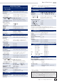
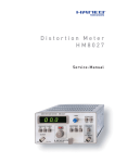
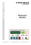
99 Washington Street
Melrose, MA 02176
Phone 781-665-1400
Toll Free 1-800-517-8431
Visit us at www.TestEquipmentDepot.com
4¾-Digit programmable Multimeter
HM8012
WDM8012 Software
(incl. delivery)
4¾ digit display with 50,000 counts
Basic accuracy 0.05%
Automatic and manual range selection
Max. resolution 10μV, 0.01dBm, 10nA, 10m , 0.1°C/°F
HZ15
PVC Test Leads
Offset function/relative value measurement in basicmeasurement
functions
Input impedance ›1G (0.5V and 5V DC range)
RS-232 interface
Mainframe
HM8001-2
PC software for control and data logging
Mainframe HM8001-2 required for operation
inklusive
Specifications
0.5-500 mA:
10A:
SPECIFICATIONS
valid at 23 deg. C after a 30 minute warm-up period
Measurement ranges: 500 mV, 5 V, 50 V, 500 V, 600 V
Resolution:
10 μV, 100 μV, 1 mV, 10 mV, 100 mV
Accuracy:
5 V, 500 V, 600 V:
±(0.05% of rdg.1) +0.002% of fs.2))
500 mV, 50 V:
± (0.05% of rdg.1) + 0.004% of fs.2))
Overload protection:
V/ /T°/dB/
against COM and to chassis:
850 Vp at max.60 Hz or 600 VDC
Low against chassis: 250 Vrms at max. 60 Hz or 250 VDC
Input resistance:
50 V, 500 V, 600 V:
10 M II 90 pF
500 mV, 5 V:
>1 G II 90 pF
Input current:
10 A
CMRR3):
≥100 dB (50/60 Hz ± 0.5%)
SMRR4)
≥ 60 dB (50/60 Hz ± 0.5%)
dB Mode
Resolution:
±(0,02 dB + 2 digits)
(display > –38,7 dBm)
0.01 dB above 18% of fs.2)
DC current
Measurement ranges:
Resolution:
Accuracy:
0,5 – 500mA:
10 A:
Voltage drop:
10 A range:
500 mA range:
other ranges:
AC + DC measurements
Same as AC + 25 Digits
DC voltages
Accuracy:
500 μA, 5 mA, 50 mA, 500 mA, 10 A
10 nA, 100 nA, 1 μA, 10 μA, 1 mA
±(0.2% of rdg.1) + 0.004% of fs.2)),
±(0.3% of rdg.1) + 0.004% of fs.2))
0.2 V max.
2.5 V max.
0.7 V max.
Resistance
Ranges:
Resolution:
Accuracy:
500 to 500 k :
5 M and 50 M :
Measurement ranges: 500 mV, 5 V, 50 V, 500 V, 600 V
Resolution:
10μV, 100 μV, 1 mV, 10 mV, 100 mV
Accuracy 0,5-50 V:
40 Hz - 5 kHz:
± (0.4% of rdg.1) + 0.07% of fs.2))
20 Hz - 20 kHz:
± (1% of rdg.1) + 0.07% of fs.2))
500 V and 600 V:
40 Hz - 1 kHz:
± (0.4% of rdg.1) + 0.07% of fs.2))
20 Hz - 1 kHz:
± (1% of rdg.1) + 0.07% of fs..2))
Overload protection:
V/ /T°/dB/
against COM and to chassis:
850 Vs at max.60 Hz or 600 VDC
Low against chassis: 250 Veff at max. 60 Hz or 250 VDC
Input impedance
AC mode:
1 M II 90pF
AC + DC mode: 10 M II 90pF
Bandwidth at -3 dB:
80 kHz typical
dB Mode:
20 Hz - 20 kHz
Accuracy (–23.8 - 59.8 dBm): ±0.2 dBm
Resolution:
0.01 dB above 9 mV
CMRR3):
≥ 60 dB (50/60 Hz ± 0.5%)
Crest factor:
7 max.
AC current
500 μA, 5 mA, 50 mA, 500 mA, 10 A
10 nA, 100 nA, 1 μA, 10 μA, 1 mA
500 , 5 k , 50 k , 500 k , 5 M , 50 M
10 m , 100 m , 1 , 10 , 100 , 1 k
±(0.05% of rdg.1)+0.004% of fs.2)+50m )
±(0.3% of rdg.1)+0.004% of fs.2))
Input protected to max. 300 Veff
Measurement current
500 – 5 k -range:
1 mA
100 μA
50 k -range:
500 k -range:
10 μA
5 - 50 M -range:
100 nA
Measurement voltage
10 V typical for open inputs, depending on the value of
resistance to be measured. Negative polarity of measurement
voltage is across common terminal.
Temperature
2-wire resistance measurement with linearization for
PT100 sensors as per standard EN60751
Range:
–200 °C to +500 °C
Resolution:
0.1°C
Measurement current: ca. 1 mA
Display:
in °C, °F
Accuracy:
–200 °C to +200 °C ± 0.4 °C + 0,0005 x T
+200 °C to +500 °C ± 0.5 °C + 0,0005 x T
(T in °C, sensor tolerance not included)
Temperature coefficient: (Reference 23°C)
V=
AC voltage
Measurement ranges:
Resolution:
Accuracy:
±(0.7% of rdg.1) +0.07% of fs.2)) for 40Hz-5kHz
± (1% of rdg.1) + 0.07% of fs.2))
V~
mA
mA-
500 mV, 50 V
600 V range
other ranges
600 V range
other ranges
all ranges
all ranges
5 M , 50 M -ranges
other ranges
30 ppm/°C
80 ppm/°C
20 ppm/°C
80 ppm/°C
50 ppm/°C
200 ppm/°C
300 ppm/°C
200 ppm/°C
50 ppm/°C
Miscellaneous
Operating conditions: + 10°C to + 40°C
max. rel. humidity:
80% (without condensation)
Power supply (from HM8001-2):
+ 5V
300 mA
~26 V
140 mA
Size (W x H x D):
135 x 68 x 228 mm
(without flat 22-pole connector)
Weight:
ca. 500g
1)
2)
rdg. = reading;
fs. = full scale;
3)
= Common mode rejection ratio;
Included in delivery: HM8012 Multimeter, Manual, HZ14 Interface cable, HZ15 PVC Test Leads,
Software-CD. Accessories: HZ10 Silicone Test
Leads, HZ812 PT100 Temperature Sensor
Subject to change without notice
21
Important hints
The istrument must be disconnected and secured
against unintentional operation if there is any suggestion that safe operation is not possible.
Important hints
The operator is requested to carefully read the
following instructions and those of the mainfra-
This may occur:
– if the instrument shows visible damage,
– if the instrument has loose parts.
– if the instrument does not function,
– after long storage under unfavourable
circumstances (e.g. outdoors or in moist
environments),
– after excessive transportation stress (e.g. in
poor packaging).
me HM8001-2, to avoid
any operating errors and
mistakes and in order to
become aquainted with the
module.
When removing or replacing the metal case, the
instrument must be completely disconnected
from the mains supply. If any measurement or
calibration procedures are necessary on the
opened-up instrument, these must only be carried
out by qualified personnel acquainted with the
danger involved.
TRIPLE POWER SUPPLY HM 8040-3
FUSE
ON/OFF
FUSE
ON/OFF
OUTPUT
HAMEG
PUSH LONG
VOLTAGE
CURRENT
VOLTAGE
CURRENT
After unpacking the module, check for any mechanical damage or loose parts inside. Should
there be any transportation damage, inform the
supplier immediately and do not put the module
into operation. This plug-in module is primarily
intended for use in conjunction with the Mainframe HM8001-2. When incorporating it into other
systems, the module should only be operated with
the specified supply voltages.
Symbols marked on equipment
ATTENTION refer to manual.
DANGER High voltage.
Protective ground (earth) terminal.
Safety
This instrument has been designed and tested in
accordance with IEC Publication 1010-1, Safety
requirements for electrical equipment for measurement, control, and laboratory use. It corresponds as well to the the CENELEC regulations EN
61010-1. All case and chassis parts are connected
to the safety earth conductor. Corresponding to
Safety Class 1 regulations (three-conductor AC
power cable). Without an isolating transformer,
the instrument's power cable must be plugged into
an approved three-contact electrical outlet, which
meets International Electrotechnical Commission
(IEC) safety standards.
Warning!
Any interruption of the protective conductor
inside or outside the instrument or disconnection of the protective earth terminal is
likely to render the instrument dangerous.
Intentional interruption is prohibited.
22
Subject to change without notice
Operating conditions
The ambient temperature range during operation
should be between +10 °C and +40 °C and should
not exceed –40 °C or +70 °C during transport or
storage. The operational position is optional, however, the ventilation holes on the HM8001-2 and
on the plug-in modules must not be obstructed.
Warranty and Repair
HAMEG instruments are subjected to a strict quality control. Prior to leaving the factory, each instrument is burnt-in for 10 hours. By intermittent
operation during this period almost all defects are
detected. Following the burn-in, each instrument
is tested for function and quality, the specifications
are checked in all operating modes; the test gear
is calibrated to national standards.
Important hints
The warranty standards applicable are those of
the country in which the instrument was sold.
Reclamations should be directed to the dealer.
Only valid in EU countries
In order to speed reclamations customers in EU
countries may also contact HAMEG directly. Also,
after the warranty expired, the HAMEG service will
be at your disposal for any repairs.
Before exchanging the module, the mainframe
must be switched off. A small circle (o) is now
revealed on the red power button in the front
centre of the mainframe.
If the BNC sockets at the rear panel of the
HM8001-2 unit were in use before, the BNC cables
should be disconnected from the basic unit for
safety reasons. Slide in the new module until the
end position is reached.
Return material authorization (RMA):
Prior to returning an instrument to HAMEG ask
for a RMA number either by internet (http://www.
hameg.com) or fax. If you do not have an original
shipping carton, you may obtain one by calling
the HAMEG sales dept (+49-6182-800-300) or by
sending an email to [email protected].
Before being locked in place, the cabinet of the
instrument is not connected to the protective earth
terminal (banana plug above the mainframe multipoint connector). In this case, no test signal must
be applied to the input terminals of the module.
Maintenance
Generally, the HM8001-2 set must be turned on
and in full operating condition, before applying any
test signal. If a failure of the measuring equipment
is detected, no further measurements should
be performed. Before switching off the unit or
exchanging a module, the instrument must be
disconnected from the test circuit.
The most important characteristics of the instruments should be periodically checked according to
the instructions provided in the sections “Operational check and “Alignment procedcure. To obtain
the normal operating temperature, the mainframe
with inserted module should be turned on at least
60 minutes before starting the test. The specified
alignment procedure should be strictly observed.
When removing the case detach mains/line cord
and any other connected cables from case of the
mainframe HM8001-2. Remove both screws on
rear panel and, holding case firmly in place, pull
chassis forward out of case. When later replacing
the case, care should be taken to ensure that
it properly fits under the edges of the front and
rear frames. After removal of the two screws at
the rear of the module, both chassis covers can
be lifted. When reclosing the module, care should
be taken that the guides engage correctly with the
front chassis.
Operation of the module
Provided that all hints given in the operating
instructions of the HM8001-2 Mainframe were
followed especially for the selection of the correct mains voltage start of operation consists
practically of inserting the module into the right
or left opening of the mainframe. The following
precautions should be observed:
Subject to change without notice
23
Control-Elements
1
16 17 19 18
2 3
4
5
6
7
8
9 10
11 12
14 15
13
Control-Elements
DISPLAY (7-segment LED + LED)
The digital display shows the measurement value
with 4¾ digit resolution, in which the largest figure is used up to “5”. It will also display various
warning messages. The measurement value will
be displayed with decimal points and polarity sign.
For DC measurement, a minus sign will appear
in front of the figures when the positive polarity
of the measured value is connected to the COM
input .
(LED)
Indicator denoting validation of the audible continuity test signal. When used as an ohmmeter,
the audible signal triggers when the measured
resistance value is less than 0.1% of the range
or 50 counts. For other functions, the indicator
is hidden.
BEEP (pushbutton)
Pushbutton for activating the audible signal.
A (safety terminal for 4 mm banana plugs)
Connection (high potential) for DC and AC
current measurements in the 10 A range in conjunction with the COM input
(low potential).
24
Subject to change without notice
Current in excess of 10 A (max. 20 A) must
not be applied for a period exceeding 30
s, otherwise the internal measurement
resistor thermal device will blow.
mA (safety terminal for 4 mm banana plugs)
Connection (high potential) for DC and AC current
measurements up to 500 mA in conjunction with
COM input
(low potential). The input is fuseprotected.
HOLD (LED)
Indicator denoting that the displayed value has
been frozen. The function can be activated using
key
. Deactivation is by pressing the HOLD/
OFFSET key.
COM (safety terminal for 4 mm bana plugs)
The COM terminal (low potential) is the common
connector for all the measurement functions to
which the potential close to the ground of the
measured quantity will be applied.
For safety reasons, the voltage across
this terminal compared to the case (guard
wire, ground) shall be 250 V at most.
OFFSET (LED)
Indicator denoting that the displayed value is a
relative measurement. The displayed value corresponds to the input value less the value present
Control-Elements
on the display during initial action on the HOLD/
OFFSET key . Activate this function by means of
a second press on the HOLD/OFFSET key.
V/ /T°/dB/
(safety terminal for 4 mm banana plugs)
Connection (high potential) for measurements of
voltages, resistances, temperatures and diode
junctions in conjunction with the COM input
(safety terminal).
For safety reasons, the voltage across
this terminal compared to the case (guard
wire, ground) shall be 600 VDC at most.
HOLD/OFFSET (pushbutton)
Pushbutton for validating the HOLD or OFFSET
functions. Pressing the key the first time will
freeze the front panel display. The HOLD indicator
then comes on. The AUTO, AC-DC, BEEP,
and
keys are inoperative.
A second press gives access to the relative mode.
The value memorized by the HOLD function is then
subtracted from each measurement before being
displayed. The OFFSET indicator
comes on.
AUTO (pushbutton)
Pushbutton for switching the AUTO range selection to the MANUAL range selection and vice
versa.
In MANUAL mode, the choice of range is left to
and
.
user initiative using the keys
Unit display zone (LED)
This zone contains a display of the measurement
units. It also identifies the function selected by
pressing the
or
key.
AC-DC (pushbutton)
This key is used for selecting the measurement
mode (DC, rms AC or rms AC + DC).
Indicators below indicate the measurement
mode:
DC: measurement of DC voltages
AC: measurement of RMS AC voltages
DC + AC: measurement of RMS AC+DC voltages.
(pushbutton)
Pushbutton for selecting the next function.
(pushbutton)
Pushbutton for selecting the previous function.
On startup, the unit switches automatically to
the DC voltmeter, MANUAL mode function and
600 voltrange.
A third press will freeze the relative value. The
HOLD
and OFFSET
indicators come on. A
fourth press will delete the HOLD and OFFSET
mode.
(pushbutton)
Pushbutton for changing to lower range. On each
press, the new range is displayed fleetingly on the
display in code form (L1 for lowest range, L2 for
second range, etc.).
(pushbutton)
Pushbutton for changing to higher range. Each
time pressed, the new range will be displayed
fleetingly on the display in code form (L1 for lowest
range, L2 for second range, etc.).
RS-232 (DB9)
Female DB9 connector intended for serial communication.
AUTO (LED)
Indicator signalling that the multimeter is in AUTOMATIC mode. In this mode, action on keys
and
is inoperative.
Subject to change without notice
25
Functions
Functions
Beginning in volt range (V) by using the keys
and
you can step through all the multimeter functions one by one, in following order:
Change to the higher range is obtained when
the value exceeds 51,000 counts. Change to the
lower range is obtained when the value drops
below 4,900 counts. It is possible to know which
range has been selected by the unit by temporarily
deactivating the AUTO mode so that the range
indication code appears fleetingly.
Measurement value display
–
–
–
–
–
–
–
–
DC or AC voltages. Input on the V/ /T°/dB and
COM connectors.
The measurement of DC or AC voltages in
decibels (reference 1 mW / 600 ). Input to
V/ /T°/dB and COM connectors.
DC or AC current up to 500 mA. Inputs on mA
and COM connectors.
DC or AC current, 10 A range. Inputs on the A
and COM connectors.
Resistors. Inputs V/ /T°/dB and COM connectors.
Temperature in degrees Celsius. Connection
of probe to V/ /T°/dB and COM connectors.
Temperature in degrees Fahrenheit. Connection of probe to V/ /T°/dB and COM connectors.
Diode test. Inputs on V/ /T°/dB and COM
connectors.
On each press, the new function is indicated by a
LED corresponding to the unit of the quantity to be
measured. It is possible to move from one function directly to any other function by a successive
series of pressings.
Mode selection
For current and voltage modes, the AC-DC key
is used for choosing between DC voltage
measurement, AC or AC + DC true rms voltage
measurement.
Range selection
In manual mode,
and
keys are used
for switching between the various measurement
ranges. The measurement ranges are split into
decades. After each range change, a code appears
indicating the new range being used. This code is
in LX form, where X is a value that may vary from
1 to 6 depending on the range and function and
L1 is the lowest range. During measurements of
unknown voltages or currents, first choose the
highest measurement range, then switch to the
range giving the most favorable display.
Measurement values are represented by 7 segment LED’s display associated with one LED for
the negative sign. The maximum value of the 1st
digit is 5; this corresponds to a 4¾ digit display
with a 50,000 counts measurement capacity. A
minus sign appears in front of the figures when,
during DC measurements, the positive polarity
of the measured value is on the COM terminal
. With the inputs short-circuited, the display
indicates (depending on the measurement range)
value zero ±2 digit. When the range is overrun,
the display shows “OFL” and an audible beep is
emitted repeatedly if it is selected. For the resistance measurement function, the exceeding
of the capacity (>50 M ) generates the “OPEN”
message.
If the multimeter is not connected to a circuit,
the display indicates random values due to the
very high input impedance for ranges of 500 mV
and 5 V.
Measurement inputs
The HM8012 has four safety terminals with which,
when using appropriate measurement cables (e.g.
HZ15), unintended contacts with the measurand
are nearly impossible. As a safety measure the
measurement cables should be checked periodically for insulation faults and, when necessary, be
replaced. The “COM” terminal is common to all
the measurement ranges. The potential close to
ground of all the measurement quantities should
be applied to this terminal. The input mA
and
is intended only for current measurements,
A
whereas the input V/ /T°/dB is designed for all
other measurements. Each terminal is appropriate to receive 4 mm banana plugs.
Test Equipment Depot - 800.517.8431 - 99 Washington Street Melrose, MA 02176
FAX 781.665.0780 - TestEquipmentDepot.com
Functions
Voltage measurements
The maximum input voltage of HM8012
is 600 V DC when the COM terminal is
to ground potential, i.e. by connecting
HM8012 to the object to be measured,
the sum of the measurement voltage and
that of the COM terminal with respect
to ground shall not exceed 600 V DC. In
this case, the maximum voltage value
between the COM terminal and ground
is 250 VDC.
For AC voltages, the true rms value of the input
voltage will be measured, and the DC component
eliminated in AC mode. If possible, the COM terminal shall be connected directly to ground or
to the point of the measurement circuit having
the lowest potential. The 0.5 V and 5 V voltage
measurement ranges are protected from input
voltages to 300 Vrms; all the other ranges are
protected to 850 Vrms.
During measurements on circuits using inductive
components, inadmissible high voltages may
appear when the circuit is opened. In such cases,
take steps to prevent the destruction of HM8012
by inductive voltages.
Input impedance in the DC range
To make the most of the excellent linearity of
the measurement system, the input impedance
for voltage measurements is very high (1 G ) for
some ranges. For instance, this makes possible
to perform accurate measurements on ranges of
up to ±5 V, even when the internal impedance of
the source to be measured is high. For instance,
for the 500 mV range, an internal 5 M source resistance will induce a maximum error of 150 μV.
Indeed, switching to the 50 V range will cause the input voltage to drop because of the input impedance
of 10 M which can cause the multimeter to switch
to the lower range and so on. After some swings,
the instrument goes into MANUAL mode.
Current measurement
For current measurements, the connection of the
object to be measured is made across the mA
terminal or to the A
terminal for currents of up
to 10 A. The AUTO mode is inhibited because there
is only one range.
The HM8012 should be connected to the circuit
whose potential with respect to ground is lowest.
must
For safety reasons, the COM terminal
not exceed 250 VDC with respect to ground.
Current ranges are protected by fuse against overloads. If the fuse blows, the cause of the overload
must be eliminated. In case of an open fuse the
instrument has to be sent in for repair. A change of
the fuse by the customer is not permitted.
AC voltage measurement
The instrument measures the true rms value of
the input voltage with or without its DC component.
To measure low voltages, or in the event of high
noise, it is necessary to use a shielded cable.
Take into account the input impedance of the multimeter. It is 1 M in the AC mode and 10 M in the
AC + DC mode. In addition, there is a slight measurement difference between these two modes due
to the input circuits. If AC measurements without
a DC component are to be made, it is preferable
to use the straight AC mode.
When the multimeter is used in AUTOMATIC mode,
there can be continuous swinging between two
ranges for frequencies above 30 kHz, because
of the frequency response difference of the two
ranges. After some swings, the instrument goes
into MANUAL mode.
Measuring errors can be caused by an overload of
the measuring amplifiers and the A/D converter.
For measurements of mixing tensions (positive or
negative DC voltage overlaid with an alternating
voltage) select a measuring range which is not
exceeded by the peak value of the alternating
voltage – the largest deviation from the reference
potential (normally 0 V). That applies also, if only
the DC voltage portion is to be measured.
A DC voltage of 350 mV is superimposed with a
sine signal with an amplitude of 200 mVp (400
mVpp). The highest deviation from 0 V amounts
550 mVp (350 mVp + 200 mVp). For DC and AC+DC
measurements the 5 V-range must be selected.
AC measurements can be done in the 500 mV
range, because then a capacitor in the entrance
suppresses the DC voltage. It is reasonable, first
to determine the height of the possibly existing
alternating voltage with AC measurement. Then
switch to DC or AC+DC function and consider the
Subject to change without notice
27
Functions
alternating voltage height with the measuring
range choice.
Resistance measurements
For resistance measurements, connect the object
and
to be measured between the COM terminal
the V/ /T°/dB terminal . There is a DC voltage
across the connection terminals. Accordingly,
only voltage-free objects need to be measured
because the voltages in the measurement circuit
will distort the result. In the case of low resistance
measurements, the OFFSET key
can be used to
compensate, where applicable, for measurement
cord resistance.
For high resistance measurements, it is advisable to place the resistance to be measured as
close as possible to the measurement terminal or
to use a shielded measurement cable connected
to ground.
The HM8012 crest factor ranges from 1 to 7 (for
additional measurement error of <1%) and depends on the magnitude of the rms value of the
signal to be measured.
To avoid saturation of the HM8012 input stages,
make sure that the input signal peak value does
not exceed 3 times the value of the range, or
850 Vp. At the middle of the measurement range,
the maximum crest factor is 7. The accuracy of
the displayed value depends, among other things,
on the rms value converter bandwidth. Complex
signal measurements will barely be influenced
when there are no harmonic components in the
measurement signal placed outside the 100 kHz
(–3 dB) bandwidth of the converter.
Protection against overloads
All the HM8012 measurement ranges are protected against various forms of overload. Precise
indications are given in the technical characteristics.
In general: during the measurement of unknown
quantities, always begin with the highest measurement range and, from then on, switch ranges
using optimum display. If HM8012 malfunctions,
first eradicate the cause before going on to make
the following measurement.
Additional error due to high crest factor
Error ± (% of reading)
CF
1-2
2-3 3-4 4-5 5-6
%
0.05 0.15 0.3
0.4 0.5
Another factor influencing the measurement precision is the duty cycle of the measurement signal.
The crest factor in this relation becomes:
Crest factor
To evaluate complex or deformed signals, the
determination of a true rms value is necessary.
The HM8012 digital multimeter will allow the
measurement of AC quantities with a display of
the true AC or AC + DC value. The crest factor
is important data for interpreting measurement
values and for evaluating its accuracy. It is defined
as the ratio between the peak voltage and the rms
value of the signal.
V
T = period duration, t = pulse duration
V = pulse voltage.
Accordingly, a rectangular signal having a duty
cycle of 1% has a crest factor of 10. The minimum
pulse duration should be approximately 10 μs.
Crest factor = CF = Vp/V RMS
Diode test
It is a measurement of the dynamic input voltage
range of the AC converter and expresses the capability of processing measurement signals with
a high peak value, without the converter entering
into saturation.
28
Subject to change without notice
Choose the diode test function
using
or
key. For diode measurements, connect the
device under test (DUT) between the COM terminal
and the V/ /T°/dB
terminal. There is
Remote control
a DC voltage across the connection terminals.
Accordingly, only voltage-free objects need to
be measured because any additional voltages in
the measurement path will distort the result. It is
preferable to remove, if necessary, any components connected to the semiconductor for precise
results. It is possible to measure voltages up to 5
V. The maximum voltage that the equipment will
supply is 10 V in an open circuit. If the cathode
of the DUT is connected to the ground (COMterminal), the diode operates in its conducting
mode. If the anode of the DUT is connected to
ground, the diode operates in its reverse mode.
For measurements on Zenerdiodes, the anode of
the device should be connected to ground. Take
care when making measurements on sensitive
circuits. The current supplied by HM8012 is
1 mA constant for this function. All keys except
,
and HOLD/OFFSET
are inactive
for this function.
Temperature measurements
Choose the temperature measurement function
(°C or °F) using
,
key. The temperature
probe is connected between the COM terminal
and the V/ /T°/dB terminal .
Temperature measurement requires a temperature probe type PT100 as per standard EN60751.
The use of another probe is possible but can
generate additional errors due to a different link
cable resistance. All keys except
,
and
HOLD/OFFSET
are inactive for this function.
After the instrument has been turned-on, the
line resistance value of the temperature probe is
automatically compensated.
On starting, simultaneously pressing BEEP
and OFFSET
will eliminate probe cable resistance compensation (zero value). In all cases,
compensation can be carried out by setting the
probe to a temperature of 0 °C and using the
OFFSET function.
Note: Measurement of the temperature probe
line resistance should be made on the same instrument used for temperature measurements.
Only this procedure guarantees the specified
measurement error.
Decibel measurements
Choose the decibel measurement function using
,
key. For decibel measurements, the
unknown input voltage is connected between the
and the V/ /T°/dB terminal.
COM terminal
The HM8012 is used for DC or AC voltage
measurements in decibels. The 0 dB reference
is defined for 1 mW power in a 600 load., i.e.
a voltage of 0.7746 V. The scale extends from
–78 dBm to 59.8 dBm.
In a 50 -system, the reference voltage for 1mW
power is 0.2236 V. In a 75 -system, the reference
voltage for 1 mW power is 0.2739 V.
If decibel measurements are made on a 50 system, add 10.8 dB to the displayed value. If
decibel measurements are made on a 75 -system,
add 9 dB to the displayed value. The mathematical
relationship is as follows:
R= Reference resistance in ; P 0 = 1 mW; V 0 in V
Sign consideration: A displayed value of –12 dB is
equivalent in 50 to: –12 dB +10.8 dB = –1.2 dB
Remote control
HM8012 includes a front panel connector
for
controlling the equipment by means of a pointto-point serial link. There are 3 wires used: RxD
(Receive Data), TxD (Transmit data), SGnd (Signal
Ground). The signal voltage levels must comply
with the following levels (±15 V max., ±3 V min.).
The link is of the bi-directional asynchronous type
with a fixed configuration: 4800 Baud, 8 bits, no
parity, one stop bit. The synchronization protocol
is XON/XOFF (half duplex) and is also fixed.
Each control must have two ASCII code characters
followed by character 13 (symbolized as <CR> in
ASCII) or two characters 13 and 10 (symbolized as
<CR> <LF> in ASCII), while the <LF> character
is ignored during reception.
The instrument internal buffer includes only
three characters, and there is no way of sending
Subject to change without notice
29
Remote control
more than one command at a time. On reception
of terminator <CR>, the equipment sends the
character 19 (<DC3> ASCII) to indicate that the
dialogue is suspended. As soon as it is possible to
resume dialogue, the instrument sends character
17 (<DC1> ASCII). The commands are divided into
fi ve groups:
Function commands
These commands are used for choosing another
magnitude to be measured and corresponding to
the choice of FUNCTION key on the front panel.
VO<CR> voltage measurement (VOLT)
AM<CR> current measurement (A)
MA<CR> current measurement (mA)
OH<CR> resistance measurement
DI<CR> diode test
TC<CR> temperature measurement in °C
TF<CR> temperature measurement in °F
DB<CR> measurement in dB.
For these commands, there is no error recovery
provided for because it is normally possible to put
the instrument in one of these states at any time.
Mode commands
Mode commands correspond to the “MODE” key
on the front panel.
DC<CR> switches the instrument to the
DC measuring mode.
AC<CR> switches the instrument to the
AC measuring mode.
AD<CR> switches the instrument to the
AC + DC measuring mode.
BY<CR> activates the continuity test beep.
BN<CR> deactivates the continuity test beep.
If the requested mode is not compatible with the
current function (e.g.: sending the AC command
while the instrument is measuring resistances),
the instrument will indicate this by a beep in
the same way as for the front panel control. In
addition, the control error indicator is set (see
command E?).
Range modification commands
These correspond to the “RANGE” keys on the
front panel.
AY<CR> switches to automatic range change
AN<CR> switches to manual range change
30
Subject to change without notice
R+ <CR> switches to the next higher range
R– <CR> switches to the next lower range.
If it is impossible to activate or deactivate the autoranging the current function (e.g. following the
AM command to switch to current measurement
the AY command cannot be executed since the
measurement is made in a single range for this
function) or if it is impossible to change ranges,
the instrument will send a beep. In addition, the
command error indicator is then set (see command E?).
Display type commands
These correspond to the choice of the HOLD
OFFSET key on the front panel.
HD<CR> switches the instrument to HOLD
O1 <CR> switches the instrument to OFFSET
(Single)
O0<CR> switches the instrument to NORMAL
L0<CR> locks the front panel. In this case,
pressing a front panel key will cause
the “rtEOn” message to appear.
L1<CR> is a way of unlocking the front panel.
The NORMAL type corresponds to a display without a reference (OFFSET) and without maintaining
(HOLD) the front panel state. In the same way as
for the manual control, it is impossible to switch to
the OFFSET mode without first going to the HOLD
mode. Indeed, the maintained measurement is
used as a reference.
The possible steps are therefore:
NORMAL (HD) → HOLD (O1) → OFFSET (HD) →
OFFSET + HOLD (O0) → NORMAL
Unlike the manual command, it is possible to
return directly to the NORMAL mode at any time
during command O0.
Status commands
The status commands are used for recovering
the status of the instrument. The returned information consists of ASCII character strings, each
terminating in a <CR>.
I? <CR> Request for equipment identification
which returns:
HAMEG, HM8012, V1.03<CR>
I.e.: manufacturer, instrument
Remote control
reference, void and software version
(Firmware).
F? <CR> Requests current measurement
function. The instrument returns one
of the following strings:
VOLT<CR>
AMP<CR>
MAMP<CR>
OHM<CR>
DIODE<CR>
TDGC<CR>
TDGF<CR>
DB<CR>
M? <CR> Requests current measurement
mode. The instrument returns one
the eight following strings:
AC BEEP-ON <CR>
AC BEEP-OFF <CR>
DC BEEP-ON <CR>
DC BEEP-OFF<CR>
AC+DC BEEP-ON <CR>
AC+DC BEEP OFF <CR>
BEEP ON <CR>
BEEP OFF <CR>
The first six answers are obtained
in voltage and current functions, the
last ones in the others.
D? <CR> Request for current display option.
The instrument sends back one of the
strings:
HOLD<CR>
REF<CR>
HOLD+REF<CR>
NORMAL<CR>
The REF string corresponds to the
front panel OFFSET mode. The NORMAL string indicates that the display
is neither on HOLD nor on REF.
R? <CR> Requests for current measurement
range. The instrument returns one of
the following strings:
NUM<CR>
NUM AUTO<CR>
The first NUM field represents a digital character indicating the current
range number. Where applicable, a
second field is displayed indicating
that the automatic range change
mode is active. Note that the range
numbers correspond respectively to:
(1 - > 0.5 V, 0.5k , 500 μA, T°C, T°F)
(2 - > 5 V, 5 k , 5 mA, Diode)
(3 - > 50 V, 50 k , 50 mA)
(4 - > 500 V, 500 k , 500 mA)
(5 - > 1000 V, 5 M )
(6 - > 50 M , 10 A)
P? <CR> This command alone is used for recovering complete parameter settings
of the equipment.
The instrument returns:
string_F, string_M, string_R,
string_D <CR>
string_F is one of the responses
returned by command F?
string_M is one of the responses
returned by command M?
string_R is one of the responses
returned by command R?
string_D is one of the responses
returned by command D?
S? <CR> Request to send current measurement. The instrument returns a string
in the shape:
NUM UNIT <CR>
NUM represents the digital value
field in IEEE NR2 format (in our case,
fi ve significant digits at most with
the presence of a decimal point). The
significant digits are those of the front
panel display.
UNIT is the field giving, as suggested
by the name, the unit or a submultiple thereof. The possible values are
identical to that of the front panel.
E? <CR> Request for status of command error
indicator. The instrument returns:
O<CR> if the command or commands
received previously have not generated an error,1<CR> if one of the
com-mands received previously has
generated an error.
The use of this command resets the
error indicator to 0. Indeed, in the
event of an error, as long as the user
has not requested the status of the
indicator through this command, the
latter will remain set even if other
commands go through without errors.
Subject to change without notice
31
Function Test
Function Test
b) AC voltage ranges
No. Range
This test should help verify, at certain intervals,
the functions of HM8012 without any great expenditure in measurement instruments. To achieve
thermal balance, the module and the basic instrument, in its case, must be energized for at least
60 minutes before the test begins.
1
500 mV
Reference
(+23 °C)
250 mV
2
5V
2.5 V
3
50 V
25 V
Measurement equipment used
4
500 V
250 V
Calibrator AC/DC for instance Fluke 5101B / Fluke
5700A / Rotek 600
Resistors of 5 k , 50 k , 500 k 0.01% for instance
model S102 J by Vishay
Resistors 500 k , 5 M 0.02%, for instance models
CNS020 by Vishay.
5
600 V
550 V
Test procedure
If one of the indicated calibrators is available or
if precision calibrators are appropriate, all the
HM8012 measurements ranges can be checked
using the following tables which indicate the limit
values. Recalibration, however, should only be
performed if the appropriate precision calibrator
is available.
Before any change of ranges, ensure that the
signal at HM8012 does not represent an unacceptable load of the object under examination. For the
link between the calibrator and HM8012, shielded
cables must be used to prevent any unwanted
influence caused by the measurement signal.
a) DC voltage ranges
No. Range
1
2
3
4
5
500 mV
5V
50 V
500 V
600 V
Reference
(+23 °C)
250 mV
2.5 V
25. V
250 V
550.00 V
Display limits
249.85 - 250.15
2.4986 - 2.5014
24.985 - 25.015
249.86 - 250.14
549.7 - 550.3
Subject to change without notice
(1) 248.65 - 251.35
(2) 247.15 - 252.85
(1) 2.4865 - 2.5135
(2) 2,4715 - 2.5285
(1) 24.865 - 25.135
(2) 24.715 - 25.285
(3) 248.65 - 251.35
(4) 247.15 - 252.85
(3) 547.3 - 552.6
(4) 544.0 - 555.9
(1) = 40 Hz to 5 kHz
(2) = 20 Hz to 20 kHz
(3) = 40 Hz to 1 kHz
(4) = 20 Hz to 1 kHz.
c) DC current ranges
No. Range
1
2
3
4
5
500 μA
5 mA
50 mA
500 mA
10 A
Reference
(+23 °C)
250.00 μA
2.5000 mA
25.000 mA
250.00 mA
1.800 A
Display limits
249.48 - 250.52
2.4948 - 2.5052
24.948 - 25.052
249.48 - 250.52
1.794 - 1.806
d) AC current ranges (f = 400 Hz)
No. Range
1
2
3
4
5
500 μA
5 mA
50 mA
500 mA
10 A
Reference
(+23 °C)
250.00 μA
2.5000 mA
25.000 mA
250.00 mA
1.800 A
Display limits
247.9 - 252.1
2.479 - 2.521
24.79 - 25.21
247.9 - 252.1
1.775 - 1.825
e) Resistor ranges
No. Range
1
2
3
4
5
6
32
Display limits
500
5k
50 k
500 k
5M
50 M
Reference
(+23 °C)
200.00
2.0000 k
20.000 k
200.00 k
2.0000 M
20.000 M
Display limits
199.83 - 200.17
1.9989 - 2.0011
19.989 - 20.011
199.89 - 200.11
1.9939 - 2.0061
19.393 - 20.061
WDM8012 Software
WDM8012 SOFTWARE
A CD-ROM is provided with the HM8012 multimeter, including the user manual, the WDM8012
software running under Windows®, as well as an
application software running under Excel®.
All instrument functions can be controlled by a
host computer through serial interface available
in standard.
The WDM8012 software is a virtual instrument
allowing the command of the instrument and the
reading of its configuration. This one can be saved
and recalled later.
When the configuration of the instrument is done,
a set of measurements can be carried out and
saved for future use.
Furthermore, the software can show deviations
of the values relative to two predetermined thresholds. A DDE link is also possible, which make
easier the integration of the instrument in specific
application software.
A software running under Excel® allows automatic drawings of curves, with a programmable
delay between successive measurement ranging
from 1s to 65 s.
Test Equipment Depot - 800.517.8431 - 99 Washington Street Melrose, MA 02176
FAX 781.665.0780 - TestEquipmentDepot.com