1
Low-cost PLC
CUSB
TM
User Manual
Version 2.1
“Everything for Embedded Control”
Comfile Technology Inc.
www.comfiletech.com
Manual Version 2.1 (revised July 2006)
Copyright 1996,2006 Comfile Technology©
1
Manual Revisions
Changes to v2.1 from v2.0
-
Updated Product Specifications for CUBLOC and CuTOUCH
-
Changed the name “Relays” to “Registers” for Ladder Logic
-
Changed the name “Name” to “Port”
-
Changed the name “Pin” under commands to “Port”
-
Clarification:
“Pin” is for actual pin number of the chip itself.
E.g. Pin 1 is SOUT.
“Port” is for Port numbers when using Commands.
E.g. out 0, 1 ‘Output logic LOW to Port 0 or P0
P0 = Port 0, NOT Pin 0
-
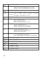
MODBUS Protocol names changed to MODBUS standard names:
Previous Term
New Term
Bit Read 01 ->
ReadCoilStatus
Bit Read 02 ->
ReadInputStatus
Word Read 03 ->
ReadHoldingRegisters
Word Read 04 ->
ReadInputRegisters
Bit Write 05 ->
ForceSingleCoil
Word Write 06 ->
PresetMultipleRegisters
Multiple Bit Write 15 ->
ForceMultipleCoils
Word Write 06 ->
PresetMultipleRegisters
Multiple Word Write 16 ->
2
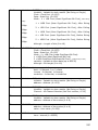
-
I2C
-
More About Interrupts Section Added
-
More about I²C Section Added
-
MODBUS RTU Master Updated
-
MODBUS RTU Slave Added
-
Appendix H for MODBUS RTU Added
PresetMultiple Registers
Warranty
Comfile Technology provides 1 Year warranty on its products against defects in
materials and workmanship. If you discover a defect, Comfile Technology will, at its
option, repair, replace, or refund the purchase price. Simply return the product with a
description of the problem and a copy of your invoice (if you do not have your invoice,
please include your name and telephone number).
This warranty does not apply if the product has been modified or damaged by accident,
abuse, or misuse.
30-Day Money-Back Guarantee
If, within 30 days of having received your product, you find that it does not suit your
needs, you may return it for a refund. Comfile Technology will refund the purchase
price of the product, excluding shipping/handling costs.
This does not apply if the
product has been altered or damaged.
Copyright & Trademarks
Copyright © 2006 by Comfile Technology Inc. All rights reserved. CUBLOC™ is a
registered trademark of Comfile Technology Inc.
WINDOWS is a trademark of
Microsoft Corporation. XPORT is trademark of Lantronix inc. Other trademarks are of
their respective companies.
Notice
This Data Book may be changed and updated without notice. For the addition of new
features, information can be updated without notice. Comfile Technology Inc. is not
responsible for any actions taken outside the explanation of this data book.
product is protected by patents across the world.
This
You may not change, copy,
reproduce, or translate without the consent of Comfile Technology Inc.
Disclaimer of Liability
Comfile Technology Inc. is not responsible for special, incidental, or consequential
damages resulting from any breach of warranty, or under any legal theory, including
lost profits, downtime, goodwill, damage to or replacement of equipment or property,
and costs or recovering, reprogramming, or reproducing any data stored in or use with
Comfile Technology products.
3
Preface
Comfile Technology has been developing PLC and BASIC controllers since
1997. With our past knowledge of this field, we are giving you a brand new
product that is more powerful, flexible, and has the best features of both
BASIC controllers and PLCs (Programmable Logic Controllers).
After experiences developing and selling TinyPLC and PicBASIC, which are
PLCs and chip based BASIC controllers, we have been able to improve our
engineering efforts every year. CUSB is able to adapt to the user’s
strengths, whether that be BASIC or LADDER. Unlike other products, you
have the option of programming the CUSB w/ Ladder Logic OR BASIC
language.
Ladder Logic, which is the traditional way of programming PLCs for its
outstanding control sequence, is neither sufficient nor easy to use for
graphic interface and other modern technology that require complex
programming. In comparison, the BASIC language proves to be simple yet
easy to implement those modern devices.
CUSB is able to handle both BASIC and Ladder Logic through on-chip multitasking. By sharing memory data, it’s able to integrate both BASIC and
LADDER efficiently and become a new type of controller by itself.
“CUSB” is created for beginners and advanced PLC users in mind. Its basic
purpose is to cut development time for the developer and also allow for lowcost alternatives to over-priced PLCs on the market today.
Comfile Technology, Inc.
4
Notice
The Start Kit or Industrial Kit you receive comes with the latest version of
Cubloc Studio.
Please be aware that the software may be upgraded often.
Please check www.comfiletech.com to download the latest version of
CublocStudio.
Please do Setup->Firmware Download after installing new version of
CublocStudio as firmware of the modules is upgraded along with our
software. (Firmware is comes automatically along w/ your new
version of CublocStudio.
Please check www.comfiletech.com often for latest Manual.
Please make sure to insert the CUBLOC module correctly as inserting it
upside-down can cause damage to the chip.
Please be aware that our 1 Year Warranty only covers defective items.
Special thanks goes to:
Mr. Alexandre Braun & Lextronics for applications on the Forum
Mr. Batman for applications on the Forum
Mr. Mauro Russo & Uniplan Software srl, Italy for User Manual Revisions
Mr. Steve Yang & Mr. Bill Ebert for Modbus RTU
Mr. Spence for website links and website bugs
5
Table of Contents
CHAPTER 1 CUSB GETTING STARTED… ...................................................................... 13
What is CUSB? ............................................................................. 14
CUSB Specifications ...................................................................... 15
Ladder Logic and BASIC ................................................................ 18
Multi-tasking of Ladder Logic and BASIC ......................................... 20
Development Environment ............................................................ 22
Download and Monitoring through the Internet................................ 23
Hints for traditional PLC User ......................................................... 24
Hints for Microcontroller User ......................................................... 25
CUSB’s Internal Structure.............................................................. 26
Peripherals................................................................................... 27
CHAPTER 2 HARDWARE............................................................................................................ 29
CUSB-22D Close-up...................................................................... 30
CUSB-22R Close-up ...................................................................... 31
CUSB-30R Close-up ...................................................................... 32
CUSB-22D I/O MAP & Dimensions ................................................ 33
CUSB-22R I/O MAP & Dimensions................................................. 34
CUSB-30R I/O MAP & Dimensions................................................. 35
CHAPTER 3 CUSB WIRING................................................................................................... 37
Connecting Power to CUSB- 22R,30R, and 36R................................ 38
Connecting Power to CUSB-22D ..................................................... 39
Keypad Controller Connection ........................................................ 40
Comfile LCD Connection ................................................................ 40
CUSB Digital Input Schematic ........................................................ 41
Connecting an NPN Proximity Sensor ............................................ 42
Connecting an PNP Proximity Sensor............................................. 43
CUSB Digital (Relay) Output Schematic......................................... 44
CUSB Digital Input/Output Test...................................................... 45
CUSB Analog Input Schematic ....................................................... 46
CHAPTER 4 CUBLOCSTUDIO EDITOR/ COMPILER............................................. 47
CUBLOC STUDIO Basics ................................................................ 48
Creating BASIC ............................................................................ 50
Debugging ................................................................................... 51
Menus ......................................................................................... 52
6
CHAPTER 5 LADDER LOGIC ................................................................................................... 55
LADDER Basics..............................................................................56
Creating LADDER...........................................................................58
Editing LADDER Text......................................................................60
Monitoring ....................................................................................64
Time Chart Monitoring ...................................................................65
WATCH POINT ..............................................................................66
Register Expression .......................................................................71
Ladder symbols.............................................................................73
Using I/Os ....................................................................................75
Use of Aliases................................................................................76
Beginning of LADDER.....................................................................77
Declare devices to use ...................................................................77
To Use Ladder Only, without BASIC ...............................................78
Enable Turbo Scan Time Mode ........................................................79
Things to Remember in LADDER .....................................................80
ladder instructions .........................................................................83
LOAD,LOADN,OUT .........................................................................85
NOT, AND,OR................................................................................86
SETOUT, RSTOUT..........................................................................87
DIFU, DIFD ...................................................................................88
MCS, MCSCLR ...............................................................................89
STEPSET.......................................................................................91
STEPOUT ......................................................................................92
TON, TAON ...................................................................................93
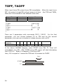
TOFF, TAOFF.................................................................................94
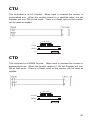
CTU .............................................................................................95
CTD .............................................................................................95
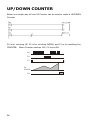
UP/DOWN COUNTER......................................................................96
KCTU ...........................................................................................97
KCTD ...........................................................................................97
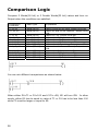
Comparison Logic ..........................................................................98
How to store Words and Double Words ..........................................99
Binary, Decimal, Hexadecimal.......................................................100
WMOV, DWMOV ..........................................................................101
WXCHG, DWXCHG.......................................................................102
FMOV .........................................................................................103
GMOV ........................................................................................104
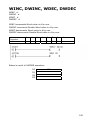
WINC, DWINC, WDEC, DWDEC.....................................................105
WADD, DWADD...........................................................................106
WSUB, DWSUB ...........................................................................106
7
WMUL, DWMUL ...........................................................................107
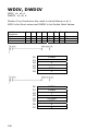
WDIV, DWDIV.............................................................................108
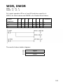
WOR, DWOR ...............................................................................109
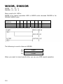
WXOR, DWXOR ...........................................................................110
WAND, DWAND...........................................................................111
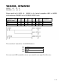
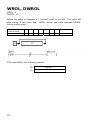
WROL, DWROL............................................................................112
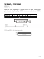
WROR, DWROR ...........................................................................113
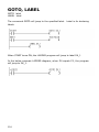
GOTO, LABEL ..............................................................................114
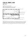
CALLS, SBRT, RET .......................................................................115
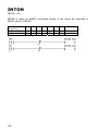
INTON ........................................................................................116
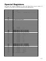
Special Registers .........................................................................117
CHAPTER 6 CUBLOC BASIC LANGUAGE..................................................................119
CUBLOC BASIC Features ..............................................................120
Simple BASIC program ................................................................122
Sub and Function.........................................................................123
Variables ....................................................................................129
String.........................................................................................130
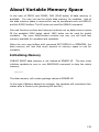
About Variable Memory Space ......................................................133
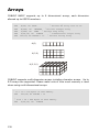
Arrays ........................................................................................134
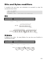
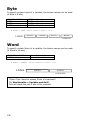
Bits and Bytes modifiers ...............................................................135
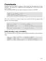
Constants ...................................................................................137
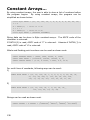
Constant Arrays... .......................................................................138
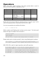
Operators ...................................................................................140
Expressing Numbers in Bits ..........................................................143
The BASIC Preprocessor...............................................................144
Conditional..................................................................................146
To use LADDER ONLY...................................................................149
To use BASIC ONLY .....................................................................149
Interrupt.....................................................................................150
More about Interrupts…................................................................151
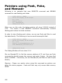
Pointers using Peek, Poke, and Memadr .......................................152
Sharing Data...............................................................................153
CHAPTER 7 CUBLOC BASIC FUNCTIONS................................................................155
Math Functions............................................................................156
Type Conversion..........................................................................158
String Functions ..........................................................................159
CHAPTER 8 CUBLOC BASIC STATEMENTS & LIBRARY..................................163
Adin( )........................................................................................164
Alias...........................................................................................166
8
Bcd2bin ......................................................................................167
Bclr ............................................................................................168
Beep ..........................................................................................169
Bfree( ) ......................................................................................170
Bin2bcd ......................................................................................170
Bin2bcd ......................................................................................171
Blen( )........................................................................................172
Bytein( ).....................................................................................173
Byteout ......................................................................................174
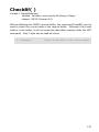
CheckBf( ) ..................................................................................175
Count( ) .....................................................................................176
Countreset..................................................................................178
Dcd............................................................................................179
Debug ........................................................................................180
Decr...........................................................................................183
Delay .........................................................................................184
Do...Loop ...................................................................................185
Dtzero........................................................................................186
Eeread( )....................................................................................187
EAdin( )......................................................................................188
Eewrite.......................................................................................190
Ekeypad .....................................................................................191
For...Next ...................................................................................192
Freqout ......................................................................................193
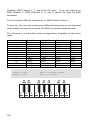
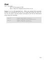
Get( ).........................................................................................195
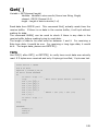
Getstr( ) .....................................................................................196
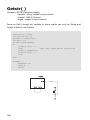
Geta...........................................................................................197
Gosub..Return.............................................................................198
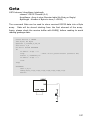
Goto ..........................................................................................198
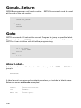
High...........................................................................................199
I2Cstart......................................................................................200
I2Cstop ......................................................................................200
I2Cread( ) ..................................................................................201
I2Cwrite( )..................................................................................201
If..Then..Elseif…Endif ...................................................................202
In( )...........................................................................................203
Incr............................................................................................204
Input..........................................................................................205
Keyin .........................................................................................206
Keyinh........................................................................................206
Keypad.......................................................................................207
Ladderscan .................................................................................208
9
Low............................................................................................209
Memadr( ) ..................................................................................210
Ncd ............................................................................................211
Nop............................................................................................212
On Int ........................................................................................213
On Ladderint Gosub .....................................................................214
On Pad Gosub .............................................................................216
On Recv1....................................................................................217
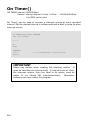
On Timer()..................................................................................218
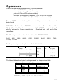
Opencom....................................................................................219
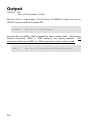
Out ............................................................................................221
Output........................................................................................222
Outstat( ) ...................................................................................223
Pause .........................................................................................223
Peek( ) .......................................................................................224
Poke...........................................................................................224
Pulsout .......................................................................................225
Put.............................................................................................226
Putstr .........................................................................................227
Puta ...........................................................................................228
Pwm...........................................................................................229
Pwmoff.......................................................................................230
Ramclear ....................................................................................231
Reverse ......................................................................................232
Rnd( ) ........................................................................................233
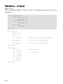
Select...Case ...............................................................................234
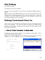
Set Debug ..................................................................................235
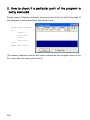
Debug Command How-to .............................................................235
Set I2c .......................................................................................238
Set Ladder on/off ........................................................................239
Set Modbus.................................................................................240
Set Pad ......................................................................................241
Set Rs232...................................................................................244
Set Until .....................................................................................245
Set Int........................................................................................246
Set Onglobal ...............................................................................247
Set Onint ....................................................................................248
Set OnLadderint ..........................................................................249
Set Onpad ..................................................................................250
Set Onrecv..................................................................................251
Set Ontimer ................................................................................252
Shiftin( ).....................................................................................253
10
Shiftout ......................................................................................254
Sys( ).........................................................................................255
Tadin() .......................................................................................256
Udelay........................................................................................257
Usepin........................................................................................258
Utmax........................................................................................259
WaitTx .......................................................................................260
CHAPTER 9 CUBLOC DISPLAY LIBRARY ...................................................................261
Cls .............................................................................................266
Csron .........................................................................................266
Csroff .........................................................................................266
Locate ........................................................................................266
Print...........................................................................................266
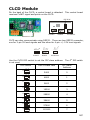
CLCD Module ..............................................................................267
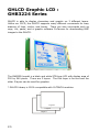
GHLCD Graphic LCD : GHB3224 Series..........................................270
Cls .............................................................................................273
Clear ..........................................................................................273
Csron .........................................................................................273
Csroff .........................................................................................273
Locate ........................................................................................273
Print...........................................................................................274
Layer .........................................................................................274
GLayer .......................................................................................275
Overlay ......................................................................................275
Contrast .....................................................................................275
Light ..........................................................................................276
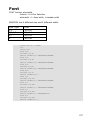
Font ...........................................................................................277
Style ..........................................................................................278
Cmode .......................................................................................279
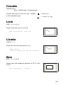
Line ...........................................................................................279
Lineto.........................................................................................279
Box............................................................................................279
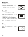
Boxclear .....................................................................................280
Boxfill.........................................................................................280
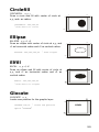
Circle .........................................................................................280
Circlefill ......................................................................................281
Ellipse ........................................................................................281
Elfill............................................................................................281
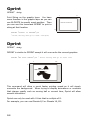
Glocate.......................................................................................281
Gprint ........................................................................................282
Dprint ........................................................................................282
11
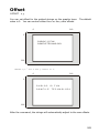
Offset .........................................................................................283
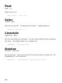
Pset ...........................................................................................284
Color ..........................................................................................284
Linestyle .....................................................................................284
Dotsize .......................................................................................284
Paint ..........................................................................................285
Arc.............................................................................................285
Defchr ........................................................................................285
Bmp...........................................................................................286
Gpush ........................................................................................287
Gpop..........................................................................................287
Gpaste .......................................................................................288
Hpush ........................................................................................289
Hpop ..........................................................................................289
Hpaste .......................................................................................289
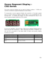
Seven Segment Display : CSG Series ............................................291
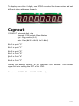
Csgdec .......................................................................................292
Csgnput......................................................................................293
Csgxput......................................................................................294
Csgdec .......................................................................................294
Csghex .......................................................................................294
CHAPTER 10 INTERFACE........................................................................................................295
CuNET ........................................................................................297
About I2C….................................................................................299
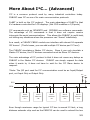
More About I²C… (Advanced)........................................................303
CHAPTER 11 MODBUS..............................................................................................................307
About MODBUS….........................................................................308
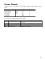
Error Check.................................................................................317
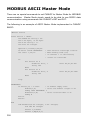
MODBUS ASCII Master Mode ........................................................318
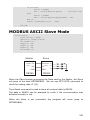
MODBUS ASCII Slave Mode..........................................................319
MODBUS RTU Master Mode...........................................................320
MODBUS RTU Slave Mode ............................................................321
APPENDIX.............................................................................................................................................326
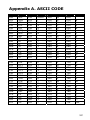
Appendix A. ASCII CODE..............................................................327
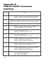
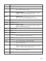
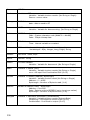
Appendix B. CUBLOC BASIC Command summary..........................328
Appendix C. MODBUS RTU Include Files .........................................339
12
Chapter 1
CUSB
Getting
started…
13
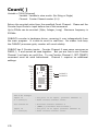
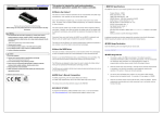
What is CUSB?
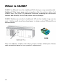
CUBLOC is different from the traditional PLCs that you may associate with.
Traditional PLCs have cases and connections like the picture below but
CUBLOC is an “On-Chip” PLC/Industrial Controller, meaning you have more
freedom and flexibility to the final product size and design.
CUBLOC Modules are similar to traditional PLCs in that Ladder Logic can be
used. But its small size allows developers to design custom PCBs just like a
microcontroller.
There are different models, each with a unique number of I/O ports. Please
make a selection based on your product’s requirement.
14
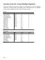
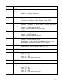
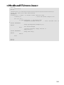
CUSB Specifications
Model
CuSB-22D
CuSB-22R
CuSB-30R
Program
Memory
(Flash)
80KB
Data Memory
(RAM)
2KB(BASIC)+1KB(Ladder Logic)
4KB
EEPROM
BASIC
Execution
Speed
Ladder Scan
Time
Serial Ports for
Communicatio
n
Digital Inputs
Digital Outputs
Analog Inputs
CuSB-36R
CB280
Processor
36,000/sec
10ms (Turbo-mode: ~100µsec)
- 2 High-speed hardware independent serial ports (Channel 0 & 1: RS232C 12V)
- Configurable Baud rates: 2400 to 230,400 bps
16 Opto-Isolated (5 to
24V DC / Min 10mA)
11 Opto-Isolated (5 to 24V DC / Min 10mA)
6 Opto-Isolated Relays
( Max. Voltage per Relay:
6A @ 250VAC or 6A @
30VDC )
10 Opto-Isolated Relays ( Max. Voltage per Relay:
5A @ 250VAC or 5A @ 30VDC )
16 Opto-Isolated Relays
( Max. Voltage per Relay:
5A @ 250VAC or 5A @
30VDC )
6 Channel 10-bit ADCs, Configurable Input Voltage: 0 to 5V or 0 to 10V
Analog
Outputs
6 Channels 16-bit PWMs (DAC) (0 to 5V)
Counters
2 Channel 16-bit High Speed Counters for 7.5 to 24V DC Pulse Input (up to 2Mhz)
1 User Configurable Timer, Configurable Interval Units = 10ms
Timer
Power
Required Power: DC
20 to 28V
- Current
Consumption w/ ports
unloaded:
Required Power: 85 to
264VAC
- Required Power: 85 to
264VAC
- Required Power: 85 to
264VAC
- Current Consumption
w/ ports unloaded:
- Current Consumption w/
ports unloaded:
- Current Consumption w/
ports unloaded:
@ 24VDC: 30mA
@ 100VAC: 33mA
- Isolated External 5
VDC
Output: 5V/600mA
@ 100VAC: 33mA
@ 200VAC: 26mA
@ 200VAC: 26mA
- Isolated External 5 and
24 VDC Outputs:
5V/500mA, 24V/300m
A
InsulationResistance
- Isolated External 5 and
24 VDC Outputs:
5V/500mA, 24V/300m
A
@ 200VAC: 32mA
- Isolated External 5 and
24 VDC Outputs:
5V/1000mA, 24V/500m
A
Input & Output & Input FG: DC500V, 100MΩ, Cut-off current: 10mA, 1Min
-Input &
Output: AC500V 1Mi
n
* Cut Off Current:
10mA, DC500V
100MΩ
WithstandingVoltage
@ 100VAC: 40mA
- Input FG: AC500V
1Min
* Cut Off Current:
10mA, DC500V
100MΩ
-Input & Output: AC2000V 1Min
* Cut Off Current: 10mA, DC500V 100MΩ
- Input FG: AC1500V 1Min
* Cut Off Current: 10mA, DC500V 100MΩ
- Output FG: AC500V 1Min
*Cut Off Current: 10mA, DC500V 100MΩ
Keypad
10~50Hz at 2G during 3 minute period, 30 minutes along X,Y and Z axis
10G for 20mS, Once on each X,Y and Z axis
Plug-N-Play Keypad Controller Support
CuNET, I2C
Support
Yes
Din-Rail Mount
Yes
Plug-N-Play LCD Support
Vibration
Impact
LCD
Operating
Temp.
-10˚ C to 50˚ C (10% to 95% RH Non-Condensing)
Storage Temp.
-10˚ C to +70˚ C (10% to 95% RH Non-Condensing)
Package
Size & Weight
RCABLE Headers: (2.5mm pitch)
RCABLE Headers: (2.5mm
pitch)
2 7-pin, 1 6-pin, 1 4-pin, 1 3-pin, 1 2-pin
3.34 x 4 x 1.8" (85 x
3.34 x 4 x 2" (85 x 104 x
3.34 x 4 x 2" (85 x 104 x
103 x 45.5mm)
51.5mm)
51.5mm)
203.5g
227g
227g
1 6-pin, 1 4-pin, 3 3-pin
4.7 x 4.3 x 2.01" (120 x
109 x 51.5mm)
301g
15
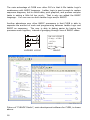
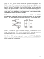
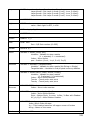
The main advantage of CUSB over other PLCs is that it fills Ladder Logic’s
weaknesses with BASIC language. Ladder Logic is good enough to replace
sequence diagrams, but to collect data, print graphics, and process complex
tasks is asking a little bit too much. That is why we added the BASIC
language. You can now run both Ladder Logic and/or BASIC!
Another advantage over other BASIC processors is that CUSB is able to
separate the amount of work and programming between Ladder Logic and
BASIC as necessary. The user is able to debug easier by having two
processes work together, instead of grudging through lines of BASIC codes.
DIM A AS INTEGER
IF IN(0) = 0 THEN
OUT 2,A
END IF
GOTO LAB1
LADDER LOGIC
BASIC
Picture of “CUBLOC Studio”, main development software for CUSB, is shown
above.
16
There are PLCs on the current market that supports both LADDER and
BASIC. These PLCs do not multi-task and run “Single-task.” BASIC is part
of their Ladder Logic and does not run independently like CUSB. This can
prove to be costly since BASIC is not real-time oriented and can affect the
Ladder Logic of the program. CUSB covers these weaknesses through its
multi-tasking features, guaranteeing accuracy and precision of timing.
Unlike many BASIC processors on the market today, CUSB supports Ladder
Logic and multi-tasking with BASIC language.
CUSB has a multi-tasking structure that runs BASIC and LADDER
simultaneously that allows accurate LADDER scan timing and still process
BASIC. You even have a choice of simply using BASIC or LADDER by itself.
SINGLE TASK
MULT I TASK
LADDER
BASIC
LADDER
BASIC
LADDER
BASIC
CUSB is a brand new type of industrial controller. By being able to do
things that traditional PLCs couldn’t through BASIC language, we have
expanded the horizons of both PLCs and BASIC micro-computers.
With 32-bit IEEE floating point math support and MODBUS ASCII/RTU
support, the user will find that CUSB is one of the most versatile BASIC/PLC
hybrid PLCs on the market today.
17
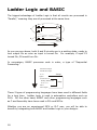
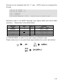
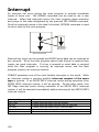
Ladder Logic and BASIC
The biggest advantage of Ladder Logic is that all circuits are processed in
“Parallel,” meaning they are all processed at the same time.
P0
A
P2
P9
P6
P8
P3
P5
B
As you can see above, both A and B circuits are in a waiting state, ready to
turn output On as soon as input is turned On. For example, if input P3
turned On, P9 would turn On.
In comparison, BASIC processes code in order, a type of “Sequential
Processing.”
Dim A As Integer
Dim B As Integer
A=0
Again:
Jump
For B=0 to 10
Debug DEC A,CR
A = A + 10
Loop
Next
Goto Again
These 2 types of programming languages have been used in different fields
for a long time. Ladder Logic is used in automation controllers such as
PLCs. On the other hand, BASIC and other programming languages such
as C and Assembly have been used in PCs and MCUs.
Whether you are an experienced MCU or PLC user, you will be able to
benefit by integrating both BASIC and Ladder Logic in your designs.
18
The biggest advantage that Ladder Logic possesses is the ability to process
input within a guaranteed slot of time. No matter how complex the circuit
becomes, Ladder Logic is always ready to output when it receives input.
This is the main reason why it’s used for machine control and other
automation fields.
Ladder Logic is more logic oriented, not a complete programming language.
To do complex processes, it has its limits. For example, to receive input
from a keypad, display to 7 Segment or LCD, and process user’s input is a
daring task for Ladder Logic.
But these things are rarely a problem for programming languages such as
BASIC.
BASIC is able to process floating point numbers, data
communications, and other things beyond the scope of what Ladder Logic
can do alone. Another advantage that BASIC has is that its language is
very similar to the English language (IF, GOTO, etc…), allowing the
beginners and the developers to learn in matter of hours, instead having to
deal with months of learning curves.
Ladder Logic
Device
Application
Advantages
Basic
Mechanism
PLC
Automation,
MachineControl
Sequencer, Bit Logic,
Timers, Counters
Parallel
Programming Languages
(BASIC, C, ASM)
PC or Micro-Computer
General Computing
Complex Math,
Data Communication,
Data Collection & Process, Analysis,
Graphic Interface
Sequential
Ladder Logic’s parallelism and BASIC sequential language both have its
advantages over each other. Ladder Logic is able to process what couldn’t
be done with BASIC. On the other hand, BASIC can easily process what is
either hard to do or couldn’t be done in Ladder Logic.
That is why we created “CUSB,” which the user is free to use both Ladder
Logic and/or BASIC based on the application being created.
After
understanding the advantages of both Ladder Logic and BASIC, the user will
be able to create more efficient final products while saving development
time and costs.
19
Multi-tasking
and BASIC
of
Ladder
Logic
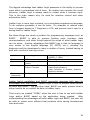
There are many ways to implement both BASIC and Ladder Logic in one
processor. The current products on the market use BASIC as part of
Ladder Logic. These products support BASIC and Ladder Logic but there is
one clear weakness.
FUNC #1
P0
P1
FUNC #1
Print "Setting Mode"
A=A+1
B = B +1
RETURN
The first weakness is that based on the execution time of BASIC, Ladder
Logic also gets affected. If the BASIC code is made up of an infinite loop,
Ladder Logic will also stop.
Ladder Logic’s main advantage is that it can process input in a guaranteed
scan-time. If Ladder Logic cannot process within this guaranteed scan-time
because of BASIC, it might be better to not include BASIC capabilities.
The second weakness is that BASIC can only be used as part of Ladder
Logic. BASIC is a powerful language by being able to process complex
algorithms. But if we can only use BASIC as part of Ladder Logic, we are
not fully using BASIC to its maximum performance.
The third point has to do with I/Os. BASIC language’s execution of I/Os
can create unwanted collisions with LADDER. The reason is that Ladder
Logic I/Os are updated while in BASIC, I/Os are directly accessed.
After solving these problems, we have created a BASIC and Ladder Logic
processor that supports real-time “multi-tasking.” BASIC runs BASIC and
LADDER runs LADDER, simultaneously without causing collision between the
each other.
20
With just BASIC, you will be able to create many devices. In comparison to
other BASIC processor on the market today, CUBLOC BASIC clearly has
faster processing speed and the upper hand on the main features. If
Ladder Logic is not necessary, the user may use just BASIC.
In the case of I/Os, the user can specifically control the I/Os used by BASIC
and LADDER, thereby eliminating I/O collision problems.
CUSB uses BASIC as its main language.
LADDER from BASIC.
We recommend controlling
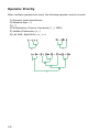
For example, there is a MASTER CONTROL feature in Ladder Logic, allowing
the user to set Control Zones. Control Zones are sections within the Ladder
Logic that the user can set entire sections of the control circuit. With the
MASTER CONTROL feature, the user can enable/disable Ladder Logic’s
Control Zones easily.
M1
P0
If A=1 THEN _M(1) = 1
If B=1 THEN _M(1) = 0
MCS 0
P2
P9
P3
MCSCLR 0
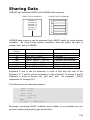
In BASIC, the user may read or write to Ladder Logic’s data memory.
In the above example, you can access Register M1 as _M(1) and write to it
from BASIC.
As you can see, CUBLOC supports BASIC and LADDER multi-tasking
simultaneously through “data memory sharing.”
21
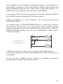
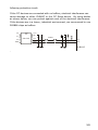
Development Environment
To use CUSB, the user may use a Windows XP, 2000, or 98 operating
system equipped computer.
If you would like to use it in
Linux/Unix/Macintosh environment, you will need to install a virtual machine
software of some type (such as VMware, etc…) that allows Windows
operating system to run on it.
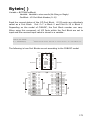
An RS232 port is also required or you may use a USB-to-RS232C converter.
Download and Monitoring is possible when connected with the PC.
RS232
6
1
2
7
3
Rx
Tx
8
4
1
24
VIN
SIN
2
23
VSS
ATN
3
RES
VSS
4
22
21
P0
5
6
20
P15
19
P14
7
8
18
P13
17
9
16
P12
P11
P5
P6
10
11
15
14
P10
P9
P7
12
13
P8
P1
DTR
P2
GND
P3
P4
9
5
SOUT
VDD
When CUSB is disconnected from the PC, it goes into a STAND-ALONE state.
The main program is stored in CUBLOC’s flash memory, and will be retained
even with no power. The user may download new programs and erase
them as many times as he or she wishes.
CUSB Ready for Programming w/ a serial cable
22
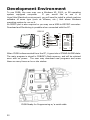
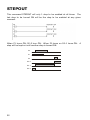
Download and Monitoring
through the Internet
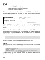
XPORT is an internet module that converts RS232 signals into TCP or UDP
packets. You can use XPORT and CUSB to download and monitor programs
through the internet.
By using this feature, you will be able to update and provide customer
service for your products even if it’s located in other parts of the world. We
provide custom XPORT firmware, Downloading/Monitoring Server programs
and embeddable applets for downloading and monitoring your CUSB. You
may use this program to manage thousands of devices.
Please refer to our CUBLOC Forum on our homepage for application notes.
(http://www.cubloc.com)
XPORT module
Monitoring/Download Server Program for multiple XPORTs
23
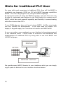
Hints for traditional PLC User
For users with much experience in traditional PLCs, they will find BASIC a
completely new language. CUSB is a PLC with BASIC language capabilities
added. The user may program only using the ladder language.
By having the option of using the BASIC language, even the PLC user may
be able to incorporate new features to the final product by making use of
BASIC, which has much powerful capability and flexibility in communicating
with other devices than PLCs.
To use CUSB, the user does not have to know BASIC. He/She may simply
use only LADDER for development. If the user does not require LCD
display or keypad usage, he or she does not need to use BASIC at all.
As you can realize, more emphasis on user interface is becoming apparent
in our industrial world. CUSB is able to overcome the deficiencies and
disadvantages of traditional PLCs by being able to use both BASIC and
LADDER language.
DISPLAY
KEYPAD
PC INTERFACE
MACHINE CONTROL
We provide many BASIC libraries for user interfaces which you can simply
copy & paste to achieve the user interface structure desired.
24
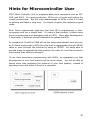
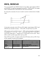
Hints for Microcontroller User
MCU, Micro Controller Unit, is programmable micro-computers such as PIC,
AVR, and 8051. For mass-production, MCUs can cut costs and reduce the
overall product size. But the main disadvantage of MCUs is that it is hard
to develop and takes a long time. For simple projects, this might be a good
route.
Even those experienced engineers feel that MCU programming is timeconsuming and not a simple task. To make a final product, it takes many
hours programming and debugging with an MCU. Even after development,
if bugs arise, it becomes almost impossible to update the MCU.
In comparison, Comfile’s CUSB will cut the users development time as much
as 20 times and provide a MCU-like chip that is upgradeable through RS232
cable or even through the internet by using an XPORT. By being able to
provide a way to upgrade the final product, the value of your final product is
much more than what you thought.
If you have experience programming with MCUs, we guarantee you that
development of your final product will be much easier. You will be able to
spend more time designing the features of your final product, instead of
spending hours and hours in front of a computer.
25
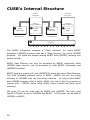
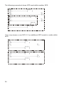
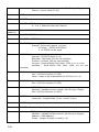
CUSB’s Internal Structure
4
SRAM
2KB~24KB
BASIC
Interpreter
LADDER
Processor
BASIC
Program Memory
LADDER
Program Memory
1
BASIC
Data Memory
FLASH
80KB
3
SRAM
1KB~4KB
2
FLASH
80KB
LADDER
Data Memory
5
I/O Ports
The BASIC interpreter contains a “Flash memory” for user’s BASIC
programs. LADDER processor also has a “Flash memory” for user’s LADDER
program. I/O ports are shared among BASIC and LADDER, allowing free
access to both.
BASIC data Memory can only be accessed by BASIC interpreter while
LADDER data memory can be accessed by both BASIC Interpreter and
LADDER Processor.
BASIC program memory(1) and LADDER(2) share the same Flash Memory.
The total available memory space is 80KB. BASIC can use the whole
memory or LADDER may use the whole memory. As long as the BASIC
and LADDER program total is within 80KB, the user is free to program as
he/she wills. (CB2XX series allow 80KB; future models will have more
memory)
I/O ports (5) can be used both by BASIC and LADDER. The user must
specify I/O ports to use in LADDER and BASIC. All I/O ports can be used in
LADDER or BASIC.
26
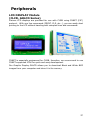
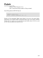
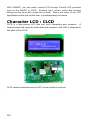
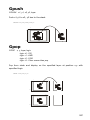
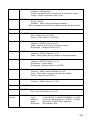
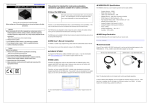
Peripherals
LCD DISPLAY Module
(CLCD, GHLCD Series)
Various LCD displays are provided for use with CUSB using CUNET (I2C)
protocol. With one line commands (PRINT, CLS, etc…), you can easily start
printing to the LCD without hassling with complex lines and commands.
CUNET is especially engineered for CUSB, therefore, we recommend to use
CUNET supported LCDs for quick and easy development.
Our Graphic Display GHLCD allows you to download Black and White BMP
images from your computer and store it in its memory.
27
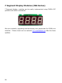
7 Segment Display Modules (CSG Series)
7 Segment display, modules can be easily implemented using CUSB’s I2C
protocol and native commands.
We are constantly upgrading and developing new peripherals for CUSB core
modules. Please check out our website www.comfiletech.com often for these
updates.
28
Chapter 2
Hardware
29
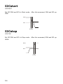
CUSB-22D Close-up
30
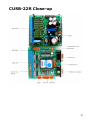
CUSB-22R Close-up
31
CUSB-30R Close-up
32
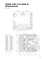
CUSB-22D I/O MAP &
Dimensions
(units: mm)
33
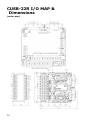
CUSB-22R I/O MAP &
Dimensions
(units: mm)
34
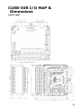
CUSB-30R I/O MAP &
Dimensions
(units: mm)
35
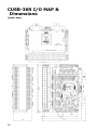
CUSB-36R I/O MAP &
Dimensions
(units: mm)
36
Chapter 3
CUSB
Wiring
37
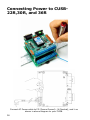
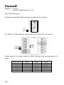
Connecting Power to CUSB22R,30R, and 36R
Connect AC Power cable to FG (Frame Ground) , N (Neutral), and L as
shown in above diagram to your CUSB.
38
Connecting Power to CUSB-22D
Please connect DC 24V to DC24 + and - on the bottom stack of the CUSB22D.
39
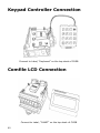
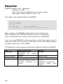
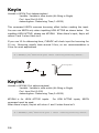
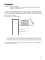
Keypad Controller Connection
Connect to Label, “Keyboard” on the top stack of CUSB
Comfile LCD Connection
Connect to Label, “CuNET” on the top stack of CUSB
40
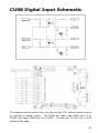
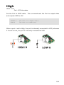
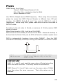
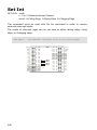
CUSB Digital Input Schematic
The diagram above shows how you can use the 24V internal power source
to connect to digital inputs. The CUSB will read Logic HIGH from 5 to
24VDC and Logic LOW from 0 to 2.4VDC. You can use TTL 5V, 12V, or 24V
sensors with ease.
41
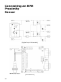
Connecting an NPN
Proximity
Sensor
(Digital Input Schematic)
(Connections)
42
Connecting an PNP
Proximity
Sensor
(Digital Input Schematic)
(Connections)
43
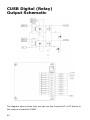
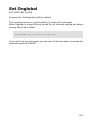
CUSB Digital (Relay)
Output Schematic
The diagram above shows how you can use the Connect AC or DC device to
the relays on-board the CUSB.
44
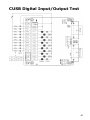
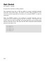
CUSB Digital Input/Output Test
45
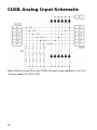
CUSB Analog Input Schematic
When SW3 is turned ON on the CUSB, AD input range changes to 0 to 10V.
*Factory default for SW3 if OFF.
46
Chapter 4
CublocStudio
Editor/
Compiler
*CublocStudio is used to program the CUSB series.
47
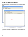
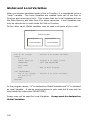
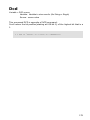
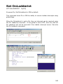
CUBLOC STUDIO Basics
After installing CUBLOC STUDIO and executing it, you will see the following
screen.
You will see that at first CUBLOC STUDIO will be in TEXT EDITOR Mode.
If you press F2, the screen will change to LADDER EDITOR Mode and if you
press F1, it will switch back to TEXT EDITOR Mode.
48
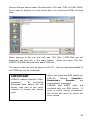
Source files are saved under file extensions .CUL and .CUB, as TWO FILES.
If you need to backup or move source files, you must save BOTH of these
files.
When opening a file, you will only see .CUL files. (.CUB files are not
displayed, but they are in the same folder). When you open .CUL file,
CUBLOC STUDIO automatically opens CUB file.
The source code can only be saved on the PC. Source code downloaded to
the CUSB can not be recovered.
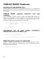
IMPORTANT
CUBLOC module supports “Codeprotection.”
By encrypting
download data, others can not
simply read part of the chip’s
memory to access the source
code.
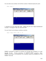
When you press the RUN button (or
CTRL-R),
Save->
Compile->
Download->
Execute
are
automatically processed.
LADDER and BASIC both are
compiled with one RUN button. If
error is found during compilation,
the screen will move to where the
error occurs.
49
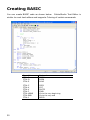
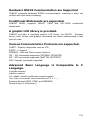
Creating BASIC
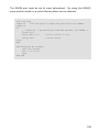
You can create BASIC code as shown below. CublocStudio Text Editor is
similar to most text editors and supports Coloring of certain commands.
50
Short-Cut
CTRL-Z
CTRL-O
CTRL-S
Explanation
UNDO
OPEN
SAVE
CTRL-C
CTRL-X
CTRL-V
CTRL-F
CTRL-HOME
CTRL-END
CTRL-Y
COPY
CUT
PASTE
FIND
Go to the very beginning
Go to the very end
REDO
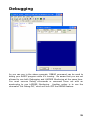
Debugging
As you can see in the above example, DEBUG command can be used to
debug your BASIC program while it’s running. Be aware that you are not
allowed to use both Debugging and LADDER Monitoring at the same time.
You must remove Debug commands or comment them out with an
apostrophe to use LADDER Monitoring. Another option is to use the
command “Set Debug Off,” which will turn OFF the DEBUG feature.
51
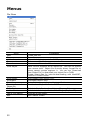
Menus
File Menu
Menu
New
Open
Ladder Import
Save
Save As
Save Object
Print Ladder
Print Basic
Print Setup
Download
from
Object file
Basic Section
Ladder Section
Last 4 Files Edited
Exit
52
Explanation
Create new file.
Open file.
Import Ladder Logic part of a CUSB program.
Save current file.
Save current file under different name.
Save current program as an object file. Use this to protect
your source code. Object file is strictly binary format file so
others cannot reverse engineer it. You can use “Download
from Object File” to download your object file to CUSB.
Create object files for internet-downloading with MaxPORT,
CuMAX or CuMAX Server.
Print Ladder Logic Section only.
Print Basic Section only.
Setup Printer for printing Ladder Logic Section.
Download an Object file to the CUSB.
Switch to Basic Section for editing. (Or press F1).
Switch to Ladder Logic Section for editing. (Or press F2).
View last 4 files edited.
Exit CUBLOC Studio
Run Menu
Menu
Run
Reset
Ladder Monitor on
BASIC Debug Terminal
Clear
CUBLOC’s
Memory
View Register Usage
Flash
Explanation
Compile Basic and Ladder, download to CUSB if there
are no errors, and restart the program automatically.
To disable automatic restart, please go to Setup>Studio Option to change.
Reset CUSB.
Start Ladder Monitoring
Open BASIC Debug Terminal Window.
This window opens automatically when there’s a
DEBUG command in the source code.
Clear CUSB’s Flash Memory.
(After Compiling) View Register usage of Ladder Logic.
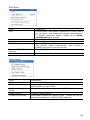
Setup Menu
Menu
PLC Setup Wizard
PC Interface Setup
Editor
Environment
Setup
Studio Options
Firmware Download
Explanation
Automatic BASIC source code generation for Ladder Logic
Setup the RS232 COM PORT for Download/Monitor.
Select COM1 through COM4.
Setup Editor Environment options for BASIC text editor.
CUBLOC Studio Options.
Download Firmware to CUBLOC CORE. Please use this to
download firmware to CUBLOC CORE manually.
53
MEMO
54
Chapter 5
Ladder Logic
WARNNING
If you do not use SET LADDER ON command, Ladder Logic will not be
executed.
55
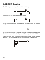
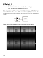
LADDER Basics
The following is an example of one switch and a lamp.
If you take out the power, the following results:
If you express the above circuit diagram as Ladder Logic, the following
results:
P0
P9
As you can see, LADDER is simply an easy way to express circuit diagrams.
A switch is comparable to the P0 port and P9 is comparable to the LAMP.
There are many ways to connect other devices such as timers, counters,
and etc… The following is an OR and AND connection in Ladder Logic:
P0
P3
56
P2
P9
In this circuit diagram, P0 and P2 and connected in logical combination of
AND. P0 and P3 are ORed. (Which mean either P0 or P3 has to be on) If
you express the above circuit diagram in Ladder Logic, it will be as follows:
In CUBLOC STUDIO, the right side is not shown. In the Ladder Logic of
CUBLOC, P0, P1, P2 are called “Registers”.
57
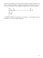
Creating LADDER
The below screen shows you how Ladder Logic is created in CUBLOC
STUDIO.
The red box shown above is the cursor for Ladder Logic. You may use the
keyboard up, down, left, and right keys or the mouse to control the red box.
After moving to the desired position, you can use keys F3~F12 to put the
desired symbol. You can also enter text for those required symbols.
58
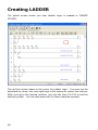
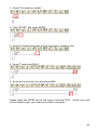
1. Press F3 to make a contact.
2. Type “START” and press ENTER.
3. Press F5 couple times and you will see that it creates a line.
4. Press F7 and type RELAY.
5. Go to the next rung (line) and press END.
Please press the ENTER key at the end of entering TEXT. At the very end
of the Ladder Logic, you must put an END command.
59
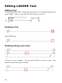
Editing LADDER Text
Editing Text
To edit an existing TEXT, please place the cursor in the desired location and
press ENTER. Now you can edit the TEXT freely as you like.
Erasing a Cell
Enter SPACE key.
Erasing a Rung (one line)
A rung is a row in Ladder. You can press CTRL-D to erase a rung. This
actually moves the rung to a buffer
60
Rung Recovery
To recover an erased rung, press CTRL-U.
Cell Insert and Delete
If you press DEL button from current position, the cell is erased and items
on the right are pulled one cell to the left.
If you press INS button from the current position, a blank cell is inserted
and items on the right are moved one cell right.
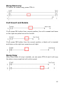
Rung Copy
When same style of rung is needed, you can press CTRL-A and it will copy
the above rung except text will not be copied.
61
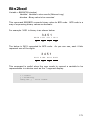
Comments
You can enter comments by adding an apostrophe (‘).
You can use a semi-colon (;) to display to the next line.
For example:
“This is Sample Program ; Date 24-Sep-2007 Comfile Technology”
62
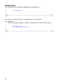
LADDER BLOCK COPY and PASTE
You can make a selection of a block to copy and paste to different parts of
the LADDER.
Use the mouse to click and drag to select the desired copy area. Press
CTRL-C to copy and CTRL-V to paste. Similar to text editing, you can press
CTRL-X to cut and paste also.
*Please be aware that in LADDER editing, UNDO is not supported.
63
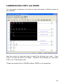
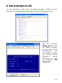
Monitoring
CUBLOC STUDIO supports real-time monitoring of Ladder Logic.
C lic k He re
Status of contacts that are ON will be displayed GREEN. Timer and
counter values will be displayed as decimal values. You can control the
monitoring speed by going to Setup Menu-> Studio option->
Monitoring speed. When the monitoring speed is too fast, it can affect
CUBLOC’s communications as monitoring takes up resources.
We
recommend value of 5 for the monitoring speed.
*Please make sure to stop monitoring before editing or downloading.
64
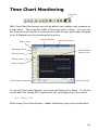
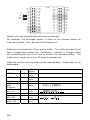
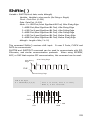
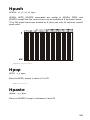
Time Chart Monitoring
Clic k He re
With Time Chart Monitoring, you will be able to see Ladder Logic contacts as
a time chart. The minimum width of the time chart is 40ms. You can use
the Zoom control function to measure the width of each pulse after stopping.
Up to 8 Registers can be monitored at one time.
Device Select
Start / Stop
Sampling Time
Zoom control
Com Port Select
Cursor Move
control icon
Relay select
Use/ Unuse
Time interval display
X position
To use the Time Chart Monitor, you must set Debug off in Basic. To do this,
simple add “Set Debug Off” command at the very beginning of your code.
Set Debug Off
While using Time Chart Monitor, Ladder Monitoring may not be used either.
65
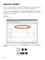
WATCH POINT
When you want to watch the status of Registers and timers outside the
current Ladder Monitoring screen, you can use Watch Point feature.
You can use two apostrophes (‘’) to add a WATCH POINT. For example,
you want to see P0 right next to some other Register that is on exact
opposite side of the screen.
Examples:
‘’P0
‘’P1
‘’D0
* Please be aware that it’s two APOSTROPHES(‘’), not a QUOTATION
MARK(“).
"
'
"
'
SHIFT + "
'
66
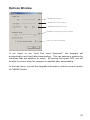
Options Window
LADDER size adjust
LADDER line space adjust
LADDER background color
LADDER monitorring speed setting
Auto run when download
If you select to use “Auto Run when download”, the program will
automatically reset itself after downloading. This can become a problem for
machines that are sensitive to resets. By turning this option OFF, you will
be able to control when the program is resetted after downloading.
In the help menu, you will find Upgrade information, and the current version
of CUBLOC Studio.
67
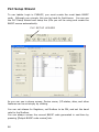
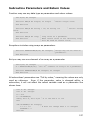
PLC Setup Wizard
To use Ladder Logic in CUBLOC, you must create the most basic BASIC
code. Although very simple, this can be hard for first-timers. You can use
the PLC Setup Wizard and setup the I/Os you will be using and create the
BASIC source automatically.
PLC SETUP WIZARD
As you can see in above screen, Device name, I/O status, alias, and other
features can be set simply by clicking.
You can set aliases for Registers, set Modbus to be ON, and set the baud
rate for the Modbus.
You can always review the current BASIC code generated in real-time by
pressing [Output BASIC code review] tab.
68
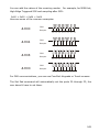
For using A/D, PWM, or COUNT, you can simply read from the D Registers
for the results. For ADC0, the AD value is stored in D(10). The user can
simply read from Register D10 to find the value of AD0.
For PWM3, the user can simply write to Register D29 to output PWM.
For HIGH COUNT1, simply read Register D39. If the user wishes, he can
change the Register to store or write values by changing the BASIC code.
Please press [Replace Basic Code] when you are done to product the final
BASIC code. Please be aware that older code will be deleted at this point.
You can also save the setup to a file by clicking on [SAVE AS..]. Click on
[LOAD…] to bring back saved setup values.
69
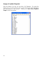
Usage of Ladder Register
With this feature, the user can see alias of all Registers. By using this
feature, the user will be able to save a great deal of time while debugging
and developing the final product. Please go to Run->View Register
Usage to open this window.
70
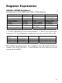
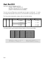
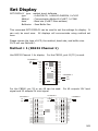
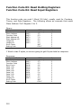
Register Expression
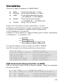
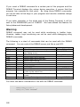
CB220, CB280 Registers
The following is a chart that shows CB220, CB280 Registers.
Register Name
Input/Output Register
P
Internal Registers M
Special Register F
Timer T
Counter C
Step Enable S
Range
P0~P127
Units
1 bit
M0~M511
F0~F127
T0~T99
C0~C49
S0~S15
Data Memory D
D0~99
1 bit
1 bit
16 bit (1 Word)
16 bit (1Word)
256 steps
( 1 Byte)
16bit (1 Word)
Feature
Interface
w/
External devices
Internal Registers
System Status
For Timers
For Counters
For Step Enabling
Store Data
P, M, and F Registers are in bit units whereas T, C, and D are in word units.
To access P, M, and F Registers in word units, you can use WP, WM, or WF.
Register
Name
WP
WM
WF
Range
Units
Feature
WP0~7
WM0~WM31
WF0~WF7
16 bit (1 Word)
16 bit (1 Word)
16 bit (1 Word)
Register P Word Access
Register M Word Access
Register F Word Access
WP0 contains P0 through P15. P0 is located in the LSB of WP0 and P15 is
located in the MSB of the WP0. These Registers are very useful to use with
commands like WMOV.
71
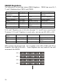
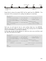
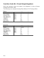
CB290 Registers
The following is a chart that shows CB290 Registers. CB290 has more M, C,
T, and D Registers than CB220 and CB280.
Register Name
Input/Output
Register P
Internal Registers
M
Special Register F
Timer T
Counter C
Step Enable S
Range
P0~P127
Units
1 bit
M0~M1023
1 bit
F0~F127
T0~T255
C0~C255
S0~S15
1 bit
16 bit (1 Word)
16 bit (1 Word)
256
steps(
1
Byte)
16 bit (1 Word)
Data Memory D
D0~511
Feature
Interface w/ External
devices
Internal Registers
System Status
For Timers
For Counters
For Step Enabling
Store Data
P, M, and F Registers are in bit units whereas T, C, and D are in word units.
To access P, M, and F Registers in word units, you can use WP, WM, or WF.
Register
Name
WP
WM
Range
Units
Feature
WP0~7
WM0~WM63
16 bit (1 Word)
16 bit (1 Word)
WF
WF0~WF7
16 bit (1 Word)
Register P Word Access
Register
M
Word
Access
Register F Word Access
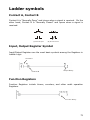
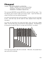
WP0 contains P0 through P15. P0 is located in the LSB of WP0 and P15 is
located in the MSB of the WP0. These Registers are very useful to use with
commands like WMOV.
72
WP0
P15
P0
WP1
P31
P16
WP2
P47
P32
WP3
P63
P48
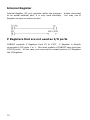
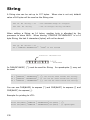
Ladder symbols
Contact A, Contact B
Contact A is “Normally Open” and closes when a signal is received. On the
other hand, Contact B is “Normally Closed” and opens when a signal is
received.
(A) Norm al Open
(B) Norm al Close
Input, Output Register Symbol
Input/Output Registers are the most basic symbols among the Registers in
Ladder Logic.
Contact A
Contact B
Output Relay
Function Registers
Function Registers include timers, counters, and other math operation
Registers.
Function Relay
73
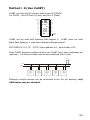
Internal Register
Internal Register (M) only operates within the program. Unless connected
to an actual external port, it is only used internally. You may use M
Register as input or output symbol.
P Registers that are not used as I/O ports
CUBLOC supports P Registers from P0 to P127. P Register is directly
connected to I/O ports 1 to 1. But most models of CUBLOC have less than
128 I/O ports. In this case, you may use the unused portion of P Registers
like M Registers.
74
Using I/Os
CUBLOC I/O ports can be used by both BASIC and LADDER. Without
defined settings, all I/O ports are controlled in BASIC. To control I/O ports
in LADDER, you must use the “Usepin” command and set the I/O ports to
be used in LADDER.
USEPIN 0,IN
USEPIN 1,OUT
The above code sets P0 as input and P1 as output for use in LADDER.
The inner processes require that USEPIN will be re-flashed in LADDER. Reflashing means that the Ladder will read I/O status beforehand and store
the status in P Registers. After scanning, LADDER will re-write the status of
I/O ports into P Registers.
INPUT REFLASH
LADDER SCAN
OUTPUT REFLASH
In BASIC, IN and OUT commands can be used to control I/O ports. This
method directly accesses the I/O ports, whether it is read or writes. In
order to avoid collision among the two, the I/Os used in BASIC and LADDER
should be specified.
One a port is declared with USEPIN command, it can only be used in
LADDER and cannot be accessed in BASIC.
USEPIN 0,IN, START
USEPIN 1,OUT, RELAY
You can also add an alias such as START or RELAY as shown above for easy
reading of the Ladder Logic.
75
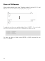
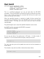
Use of Aliases
When creating Ladder Logic using “Register numbers” such as P0, P1, and
M0, the user can use alias to help simplify their programs.
In order to use alias, you need to declare them in BASIC. You can simply
use ALIAS command to use ALIAS for Registers you desire to use.
ALIAS M0 = MAINMOTOR
ALIAS M2 = STATUS1
ALIAS M4 = MOTORSTOP
You have an option of either using USEPIN or ALIAS command to use
aliases in LADDER.
76
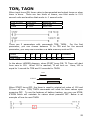
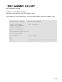
Beginning of LADDER
CUBLOC executes BASIC first. You can set LADDER to start by using the
command “SET LADDER ON”. When this command is executed, LADDER is
executed consistently within the specified scan time of 10 milliseconds.
If you do not use SET LADDER ON command, Ladder Logic will not be
executed.
SET LADDER ON
Declare devices to use
You must declare the device to be used so the compiler knows.
following are examples of how to use the CONST DEVICE command.
CONST DEVICE = CB220
‘ Use CB220.
CONST DEVICE = CB280
‘ Use CB280.
The
or
This command must be placed at the very start of the program.
77
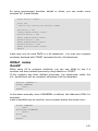
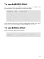
To Use Ladder Only,
without BASIC
You must at least do a device declaration, port declaration, and turn on the
LADDER for BASIC even if you are going to only use Ladder.
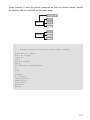
The following is an example of such minimal BASIC code:
Const Device = CB280
'Device Declaration
Usepin
Usepin
Usepin
Usepin
'Port Declaration
0,In,START
1,In,RESETKEY
2,In,BKEY
3,Out,MOTOR
Alias M0=RELAYSTATE 'Aliases
Alias M1=MAINSTATE
78
Set Ladder On
'Start Ladder
Do
Loop
'BASIC program will run in infinite loop/
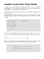
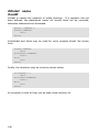
Enable Turbo Scan Time Mode
In order to use both BASIC and LADDER, a scan time of 10ms is supported
for LADDER. If you would like to enable Turbo Scan Time Mode when not
using BASIC, you can follow the example below.
LADDERSCAN command can be used inside a DO…LOOP to enable Turbo
Scan Time Mode.
Depending on the size of the Ladder program, this scan time MAY change.
For small programs less than 50 rungs, a scan time of 500us to 1ms are
possible.
Const Device = CB280
Usepin 0,In,START
Usepin 1,In,RESETKEY
Usepin 2,In,BKEY
Usepin 3,Out,MOTOR
Alias M0=RELAYSTATE
Alias M1=MAINSTATE
Do
LadderScan
Loop
'Device Declaration
'Port Declaration
'Aliases
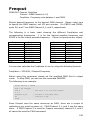
F16 is a special Register for checking the current scan time. You can
connect it to an I/O port as shown below and check it with an oscilloscope.
Below is an example of a conditional case where Turbo Scan Time is used.
Only when Register M0 is ON, will the Turbo Scan Time be enabled.
.
Do
Set Ladder On
’10 ms Scan when M0 is OFF
Do While _M(0) = 1
LadderScan
‘Only Execute when M is ON
Loop
Loop
79
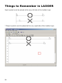
Things to Remember in LADDER
Input symbol must be placed at the very left side of the Ladder Logic.
* Output symbol must be placed at the very right side of the Ladder Logic.
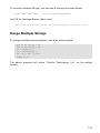
80
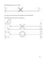
Identical outputs must not collide.
You may not use more than one vertical line as shown below.
More than 1 division will give compile error
81
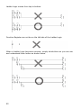
Ladder Logic moves from top to bottom.
Function Register can not be on the left side of the Ladder Logic.
When a Ladder Logic becomes complex, simply divide them so you can see
and understand them better as shown below.
82
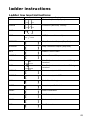
ladder instructions
Ladder low level instructions
Command
LOAD
Symbol
Explanation
Contact A (Normally Open)
LOADN
Contact B (Normally Closed)
OUT
Output
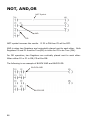
NOT
NOT (Inverse the result)
STEPSET
Step Controller Output (Step Set)
STEPOUT
Step Controller Output (Step Out)
MCS
Master Control Start
MCSCLR
Master Control Stop
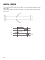
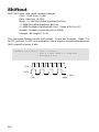
DIFU
Set ON for 1 scan time when HIGH signal
received
DIFD
Set ON for 1 scan time when LOW signal
received
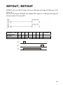
SETOUT
Maintain output to ON
RSTOUT
Maintain output to OFF
END
End of Ladder Logic
GOTO
Jump to specified label
LABEL
Label Declaration
CALLS
Call Subroutine
SBRT
Declare subroutine
RET
End Subroutine
83
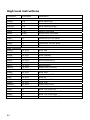
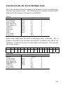
High level instructions
Command
Parameter
Data Transfer Commands
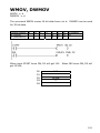
WMOV
s,d
DWMOV
s,d
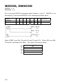
WXCHG
s,d
DWXCHG
s,d
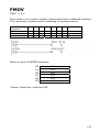
FMOV
s,d,n
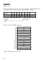
GMOV
s,d,n
Increment/Decrement Commands
WINC
d
DWINC
d
WDEC
d
DWDEC
d
Math Commands
WADD
s1,s2,d
DWADD
s1,s2,d
WSUB
s1,s2,d
DWSUB
s1,s2,d
WMUL
s1,s2,d
DWMUL
s1,s2,d
WDIV
s1,s2,d
DWDIV
s1,s2,d
Logical Operation Commands
WAND
s1,s2,d
DWAND
s1,s2,d
WOR
s1,s2,d
DWOR
s1,s2,d
WXOR
s1,s2,d
DWXOR
s1,s2,d
Bit Shift Commands
WROL
d
DWROL
d
WROR
d
DWROR
d
84
Explanation
Word Data Move
Double Word Data Move
Word Data Exchange
Double Word Data Exchange
Data fill command
Group move command
Increment 1 to the Word
Increment 1 to the Double Word
Decrement 1 to the Word
Decrement 1 to the Double Word
Word Add
Double Word Add
Word Subtract
Double Word Subtract
Word Multiplication
Double Word Multiplication
Word Division
Double Word Division
Word AND
Double Word AND
Word OR
Double Word OR
Word XOR
Double Word XOR
Word 1 bit Shift Left
Double Word 1bit Shift Left
Word 1 bit Shift Right
Double Word 1 bit Shift Right
LOAD,LOADN,OUT
LOAD is for Normally Open Contacts and LOADN is for Normally Closed
Contacts.
LOAD
OUT
LOADN
Registers that
can be used
LOAD
LOADN
OUT
P
M
F
S
C
T
O
O
O
O
O
O
O
O
D
Constants
P0
P2
P1
P3
85
NOT, AND,OR
NOT Symbol
AND
OR
NOT symbol inverses the results. If P0 is ON then P5 will be OFF.
AND is when two Registers are horizontally placed next to each other. Both
Registers P0 and P1 must be True(ON) in order for P5 to be True (ON).
For OR operation, two Registers are vertically placed next to each other.
When either P0 or P1 is ON, P5 will be ON.
The following is an example of BLOCK AND and BLOCK OR.
BLOCK AND
BLOCK OR
86
SETOUT, RSTOUT
SETOUT will turn ON P5 when P0 turns ON and will keep P5 ON even if P0
turns off.
On the other hand, RSTOUT will output OFF when P1 is ON and will keep P5
off even when P1 turns OFF.
Registers that
can be used
SETOUT
RSTOUT
P
M
F
O
O
O
O
O
O
S
C
T
D
Constant
s
P0
P1
P5
87
DIFU, DIFD
This command DIFU turns ON the output 1 scan time when input goes from
OFF to ON.
Conversely, DIFD turns OFF the output 1 scan time when input goes from
ON to OFF.
DIFU
DIFD
P0
P1
P5
P6
88
1 SC AN
1 SC AN
MCS, MCSCLR
The command MCS and MCSCLR allow for the Ladder Logic between MCS X
and MCSCLR X to be executed when turned ON. If MCS is OFF, the Ladder
Logic in between MCS X and MCSCLR X will not be executed.
By using this command, the user is able to control a whole block of Ladder
Logic.
MCS # (0~7)
In the above example, when M0 turns ON, Ladder Logic between MCS 0 and
MCSCLR are executed normally. If M0 is OFF, P5 and P6 will turn OFF.
MCS number can be used from 0 to 7. MCS number should be used from 0
increasingly to 1, 2, 3, etc… MCS 1 must exist inside MCS 0 and MCS 2
must exist inside MCS 0. Likewise up to 7 MCS blocks can be used. When
MCS 0 is OFF, all MCS inside MCS 0 will turn OFF.
When MCS turns OFF, all outputs within that MCS block will turn OFF, Timer
will be resetted, Counter will be stopped.
Command
OUT
SETOUT
RSTOUT
Timer
Counter
Other
Commands
When MCS is ON
Normal Operation
Normal Operation
Normal Operation
Normal Operation
Normal Operation
Normal Operation
When MCS is OFF
OFF
Maintain status after MCS turned OFF
Maintain status after MCS turned OFF
Reset to default value
Maintain status after MCS turned OFF
Stop Operation
89
The following screenshot shows MCS used within another MCS.
*You may simply re use MCS 0 if no additional MCS needs to reside within
MCS.
90
Step Control
S Register are used for step control. The following is the correct format for
step control.
Relay ( 0~15 )
Step # ( 0~255 )
S7:126
In Step Control, there’s “normal step” and “reverse step”. For normal step,
we can simply use the STEPSET command.
STEPSET
This command STEPSET will turn ON the current step if the previous step
was ON. Since it operates in one step at a time, we call it STEPSET. For
example, in the above ladder diagram, when P1 turns ON, S0:2 is turned
ON if S0:1 is turned ON. S0:1 is turned OFF. When P2 turns ON, S0:0 is
turned ON and other steps are turned off. S0:0, or step 0 is used for reset.
Otherwise STEPSET will move in order.
P0
P1
P2
S0:0
S0:1
S0:2
91
STEPOUT
This command STEPOUT will only 1 step to be enabled at all times. The
last step to be turned ON will be the step to be enabled at any given
moment.
When P1 turns ON, S0:2 turn ON. When P0 turns on S0:1 turns ON. A
step will be kept on until another step is turned ON.
P0
P1
P2
S0:0
S0:1
S0:2
92
TON, TAON
When input turns ON, timer value is decremented and output turns on when
timer is done. There are two kinds of timers, one that works in 0.01
second units and another that works in .1 second units.
Type of Timer
TON
TAON
Time units
0.01 sec
0.1 sec
Maximum Time
655.35 sec
6553.5 sec
There are 2 parameters with commands TON, TAON.
For the first
parameter, you can choose between T0 to T99 and for the second
parameter, you may use a number or a data memory such as D0.
Usable
Registers
TON, TAON
P
M
F
S
C
T
D
Constants
O
O
O
O
In the above LADDER diagram, when START turns ON, T0 Timer will start
from zero to 100. When 100 is reached, T0 will turn on. Here, 100 is
equal to 1 second for TON and 10 seconds for TAON.
1sec
START
T0
When START turns OFF, the timer is reset to original set value of 100 and
T0 turn off too. TON, TAON commands will reset its timer values upon
powering OFF. To use the features of battery backup, you can use KTON,
KTAON which will maintain its values when powered OFF. Below is an
example of how to reset TAON.
93
TOFF, TAOFF
When input turns ON, output turns ON immediately. When the input turns
OFF, the output is kept ON until set amount of time. Like TON and TAON,
there are 2 commands for two different time units.
Type of Timer
TOFF
TAOFF
Time units
0.01 sec
0.1 sec
Maximum Time
655.35 sec
6553.5 sec
There are 2 parameters with commands TO F F , TAO F F For the first
parameter, you can choose between T0 to T99 and for the second
parameter, you may use a number or a data memory such as D0.
Usable
Registers
TOFF, TAOFF
P
M
F
S
C
T
D
Constants
O
O
O
O
In the above LADDER diagram, when START turns ON, T0 Timer will
immediately turn ON. After START turns OFF, timer will start decreasing
from 100 to 0. When 0 is reached, T0 will turn OFF.
Here, 100 is equal to 1 second for TON and 10 seconds for TAOFF.
1sec
START
T0
94
CTU
This command is an UP Counter. When input is received the counter is
incremented one. When the counter counts to a specified value, the set
Register will turn ON at that point. There is a Reset input so the counter
can be reset as needed.
100 pulse
PULSE
RESET
C0
CTD
This command is a DOWN Counter. When input is received the counter is
decremented one. When the counter reaches 0, the set Register will turn
ON at that point. There is a Reset input so the counter can be reset as
needed.
100 pulse
PULSE
RESET
C1
95
UP/DOWN COUNTER
Below is a simple way of how UP Counter can be used to make a UP/DOWN
Counter.
P0 is for counting UP, P2 is for counting DOWN, and P1 is for resetting the
COUNTER. When Counter reaches 100, C0 turns ON.
P0
P2
P1
C0
COU NT
C0
96
KCTU
This command is exactly same as CTU command except, this command will
be able to remember counter value when module is powered off. The
module used for this command MUST support battery backup(CB290). In
comparison, CTU command will lose its count value when the module is
powered off.
100 pulse
P0
P1
C0
Use RESET to set the
counter to 0 at the
beginning
Power off & on
When using this command for the very first time, please use the RESET
signal to reset the counter value. Otherwise counter will start at the last
value it was set. (random if not set before)
KCTD
This command is exactly same as CTD command except, this command will
be able to remember counter value when module is powered off. The
module used for this command MUST support battery backup(CB290). In
comparison, CTD command will lose its count value when the module is
powered off.
KCTU, KCTD must be used with modules that support “Battery-Backup”
such as the CB290.
97
Comparison Logic
Compare 2 Words(16 bit) or 2 Double Words(32 bit) values and turn on
Output when the conditions are satisfied.
Comparison
Command
=, s1, s2
<>, s1, s2
Data Types
Explanation
Word(16 bit)
Word(16 bit)
>, s1, s2
<, s1, s2
>=, s1, s2
<=, s1, s2
D=, s1, s2
D<>, s1, s2
Word(16 bit)
Word(16 bit)
Word(16 bit)
Word(16 bit)
DWord(32 bit)
DWord(32 bit)
D>, s1, s2
D<, s1, s2
D>=, s1, s2
D<=, s1, s2
DWord(32 bit)
DWord(32 bit)
DWord(32 bit)
DWord(32 bit)
When s1 and s2 are same Output turns ON.
When s1 and s2 are different, Output turns
ON.
When s1 > s2, Output turns ON.
When s1 < s2, Output turns ON.
When s1 >= s2, Output turns ON.
When s1 <= s2, Output turns ON.
When s1 and s2 are same Output turns ON.
When s1 and s2 are different, Output turns
ON.
When s1 > s2, Output turns ON.
When s1 < s2, Output turns ON.
When s1 >= s2, Output turns ON.
When s1 <= s2, Output turns ON.
You can mix different comparisons as shown below:
When either D0=T1 or D1<100 and if C0>=99, M0 will turn ON. In other
words, either D0 has to equal to value of T1 or D1 has to be less than 100
while C0 must be larger or equal to 99.
98
How to store
Words and Double Words
Byte is 8 bits, Word is 16 bits, and Double Word is 32 bits.
1 BYTE
1 WORD
DOUBLE WORD
There are 2 ways to store Word of Double Word size of data. A Word or
Double Word can be stored starting from the LOW BYTE or from the HIGH
BYTE. In CUBLOC, it is stored from the LOW BYTE or LSB(Least Significant
Byte).
As you can see below, 1234H is
stored in Memory Address 0 and
12345678H is stored in Memory
Address 5.
In every Memory
Address, 1 byte of data is stored.
0
1
2
3
4
5
6
7
8
9
34
12
78
56
34
12
The Registers C, T, D are in units of Words. To store a Double Word data,
2 Word spaces will be required, meaning two Register spaces. Below is an
example of store a Double Word data, 12345678H. D1 gets 1234H and D0
gets 5678H.
D0
D1
D2
D3
D4
5678
1234
99
Binary, Decimal, Hexadecimal
To program well, we need to know binary decimal, and hexadecimal
numbers. The following chart shows the relationships between these three
types of number representation.
Decimal
0
1
2
3
4
5
6
7
8
9
10
11
12
13
14
15
Binary
0000
0001
0010
0011
0100
0101
0110
0111
1000
1001
1010
1011
1100
1101
1110
1111
Hexadecimal
0
1
2
3
4
5
6
7
8
9
A
B
C
D
E
F
In CUBLOC’s Ladder Logic, we express binary and hexadecimal numbers in
the following manner:
Binary:
Hexadecimal:
00101010B
0ABCDH
We put a B at the end of the binary number and an H for hexadecimal
numbers. To clearly identify that ABCD is a number, we can put a 0 in
front of the hexadecimal number.
(E.g. : 0ABH, 0A1H, 0BCDH )
*In BASIC, it is slightly different from LADDER in the way you express
binary and hexadecimal numbers. We use &B100010 or &HAB to express
those type of numbers.
100
WMOV, DWMOV
WMOV s, d
DWMOV s, d
The command WMOV moves 16 bit data from s to d. DWMOV can be used
for 32 bit data.
Usable Register
s (Source)
d (Destination)
P
M
F
S
C
O
O
T
O
O
D
O
O
Constants
O
When input START turns ON, D0 will get 100. When IN0 turns ON, D2 will
get 1234H.
D0
D1
D2
D3
D4
100
1234H
0
101
WXCHG, DWXCHG
WXCHG s, d
DWXCHG s, d
The command WXCHG exchanges data between s and d. WXCHG is for
exchanging 1 Word and DWXCHG is for exchanging Double Word.
Usable
Registers
s
d
P
M
F
S
C
T
D
O
O
O
O
O
O
Constants
When START turns ON, D0 gets 100 and D1 gets 123. When IN0 turns ON,
D0 and D1 exchange their data. The result is as shown below:
D0
D1
D2
D3
D4
102
123
100
FMOV
FMOV s, d, n
Store value in s to d and n number of times after that to additional locations.
This command is usually used for initializing or clearing memory.
Usable
Registers
s
d
n
P
M
F
S
C
T
D
O
O
O
O
O
O
Constants
O
Below is result of LADDER execution:
D0
D1
D2
D3
D4
D5
100
100
100
100
100
100
*Notice: Please Set n less than 255.
103
GMOV
GMOV s, d, n
Store value starting at s to d by n memory locations. Please make sure not
to overlap memory locations as this could cause data collisions.
Usable
Registers
s
d
n
P
M
F
S
C
T
D
O
O
O
O
O
O
O
Below is result of LADDER execution:
D0
D1
D2
D3
D4
D5
D6
D7
D8
D9
D10
D11
D12
D13
D14
D15
D16
*Notice: Please Set n less than 255.
104
Constants
12
34
56
78
90
12
34
56
78
90
WINC, DWINC, WDEC, DWDEC
WINC d
DWINC d
WDEC d
DWDEC d
WINC increments Word value in d by one.
DWINC increments Double Word value in d by one.
WDEC decrements Word value in d by one.
DWDEC decrements Double Word value in d by one.
Usable
Registers
d
P
M
F
S
C
T
D
O
O
O
Constants
Below is result of LADDER execution:
D0
D1
D2
D3
99
105
WADD, DWADD
WADD s1, s2, d
DWADD s1, s2, d
Add s1 and s2 and store result in d.
WADD is for Word values and DWADD is for Double Word Values.
Usable
Registers
s1
s2
d
P
M
F
S
C
T
D
Constants
O
O
O
O
O
O
O
O
O
O
O
WSUB, DWSUB
WSUB s1, s2, d
DWSUB s1, s2, d
Subtract s2 from s1 and store result in d.
WSUB is for Word values and DWSUB is for Double Word Values.
Usable
Registers
s1
s2
d
P
M
F
S
C
T
D
Constants
O
O
O
O
O
O
O
O
O
O
O
D1 gets 95 in the above LADDER diagram.
106
WMUL, DWMUL
WMUL s1, s2, d
DWMUL s1, s2, d
Multiply s1 and s2 and store result in d.
WMUL is for Word values and DWMUL is for Double Word Values.
Usable
Registers
s1
s2
d
P
M
F
S
C
T
D
Constants
O
O
O
O
O
O
O
O
O
O
O
The result of 1234H * 1234H is stored in D1 as a double word of 14B5A90H.
D0
D1
D2
1234H
5A90H
14BH
The result of 123456H * 1234H is stored as 4B60AD78H in D2
D0
D1
D2
D3
D4
D5
3456H
0012H
0AD78H
4B60H
0
0
107
WDIV, DWDIV
WDIV s1, s2, d
DWDIV s1, s2, d
Divide s1 by s2 and store the result in d and leftover in d+1.
WDIV is for Word values and DWDIV is for Double Word Values.
Usable
Registers
s1
s2
d
108
P
M
F
S
C
T
D
Constants
O
O
O
O
O
O
O
O
O
O
O
D0
D1
D2
D3
D4
D5
1234H
D0
D1
D2
D3
D4
D5
D6
D7
5678H
1234H
7
0
0C335H
299H
5
0
3
611H
1
WOR, DWOR
WOR s1, s2, d
DWOR s1, s2, d
Do Logical operation OR on s1 and S2 and store result in d.
WOR is for Word values and DWOR is for Double Word Values.
Usable
Registers
s1
s2
d
P
M
F
S
C
T
D
Constants
O
O
O
O
O
O
O
O
O
O
O
The result of above ladder diagram:
D0
D1
D2
1200H
34H
1234H
109
WXOR, DWXOR
WXOR s1, s2, d
DWXOR s1, s2, d
Store result of s1 XOR s.
WXOR is for logical operation XOR in WORD units whereas DWXOR is for
DOUBLE WORD units.
Usable
Registers
s1
s2
d
P
M
F
S
C
T
D
Constants
O
O
O
O
O
O
O
O
O
O
O
The following is result of above LADDER:
D0
D1
D2
1234H
0FFH
12CBH
When you want to invert specific bits, you can use XOR logical operation.
110
WAND, DWAND
WAND s1, s2, d
DWAND s1, s2, d
Store result of s1 AND s2. WAND is for logical operation AND in WORD
units whereas DWAND is for DOUBLE WORD units.
Registers that
may be used
s1
s2
D
P
M
F
S
C
T
D
Constants
O
O
O
O
O
O
O
O
O
O
O
The results of execution of LADDER above:
D0
D1
D2
1234H
0FFH
34H
You can use AND operation when you want to use specific bits only.
111
WROL, DWROL
WROL d
DWROL d
Rotate the value on Register d 1 (double) word to the left. The value left
gets stored in the Carry flag. WROL moves one word whereas DWROL
moves double word.
Registers
that
may be used
d
C
P
M
F
S
C
T
D
O
O
O
d
If D0 has 8421H, the following results:
D0
D1
112
0843H
Constants
WROR, DWROR
WROR d
DWROR d
Rotate the value on Register d 1 (double) word to the right. The value left
gets stored in the Carry flag. WROL moves one word whereas DWROL
moves double word.
Registers that
may be used
d
P
M
F
S
C
T
D
O
O
O
d
Constants
C
If D1 has 8421H, the following results:
D0
D1
0C210H
113
GOTO, LABEL
GOTO label
LABEL label
The command GOTO will jump to the specified label. Label is for declaring
labels.
When START turns ON, the LADDER program will jump to label SK_1
In the below example LADDER diagram, when D0 equals C0, the program
will jump to SK_1.
114
CALLS, SBRT, RET
CALLS label
SBRT label
CALLS will call a sub-routine.
SBRT is the starting point for a sub-routine.
RET is the ending point for a sub-routine.
Main Prog ram
RETm ust b e use d when
there a re sub -routines
Sta rt of sub -routine
End of sub -routine
End o f La dd er
Please be aware that when adding sub-routines to your program, you need
to add RET to the end of main program to differentiate from sub-routines.
END goes at the very end of main program and sub-routines in this case.
115
INTON
INTON s,d
INTON is same as WMOV command except it can cause an interrupt in
BASIC part of CUBLOC.
Usually
Registers
s (Source)
d (Destination)
116
P
M
F
S
C
T
D
Constants
O
O
O
O
O
O
O
Special Registers
You can use special Registers to find out about the current status of
CUBLOC or use them for timing functions and applications.
Special Register
F0
F1
F2
F3
F4
F5
F6
F7
F8
F9
F10
F11
F12
F13
F14
F15
F16
F17
F18
F19
F20
F21
F22
F23
F24
F25
F26
F27
F28
F29
F30
F31
F32
F33
F34
F35
F36
F37
F38
F39
F40
F41
F42
Explanation
Always OFF
Always ON
Turn on 1 SCAN time at POWER UP (Set Ladder On).
1 SCAN On every 10ms
1 SCAN On every 100ms
Repeat ON/OFF every 1 Scan time.
Repeat ON/OFF every 2 Scan times.
Repeat ON/OFF every 4 Scan times.
Repeat ON/OFF every 8 Scan times.
Repeat ON/OFF every 16 Scan times.
Repeat ON/OFF every 32 Scan times.
Repeat ON/OFF every 64 Scan times.
Repeat ON/OFF every 128 Scan times.
Repeat ON/OFF every 10ms
Repeat ON/OFF every 20ms
Repeat ON/OFF every 40ms
Repeat ON/OFF every 80ms
Repeat ON/OFF every 160ms
Repeat ON/OFF every 320ms
Repeat ON/OFF every 640ms
Repeat ON/OFF every 1.28 seconds
Repeat ON/OFF every 5.12 seconds
Repeat ON/OFF every 10.24 seconds
Repeat ON/OFF every 20.48 seconds
Repeat ON/OFF every 40.96 seconds
Repeat ON/OFF every 81.92 seconds
Repeat ON/OFF every 163.84 seconds
Repeat ON/OFF every 327.68 seconds
Repeat ON/OFF every 655.36 seconds
Call LADDERINT in BASIC
117
* If you write 1 to F40, you can create a LADDERINT in BASIC. Please
refer to ON LADDERINT GOSUB command for details.
* F2 causes 1 Scan ON at the time of BASIC’s SET LADDER ON command.
*Blank special Registers are reserved. Please do not use them.
118
Chapter 6
CUBLOC
BASIC
Language
IMPORTANT
You must declare the device being used before using BASIC or LADDER.
CONST DEVICE = CB280
‘ Use CB280 for CUSB Series
119
CUBLOC BASIC Features
Interface PC with RS232C Port
CUBLOC BASIC uses RS232 port to interface with the PC. You also have
option of using it to connect to XPORT and use monitoring/downloading via
the internet.
CUBLOC BASIC
routines.
supports
functions
and
sub
Like C language, the user is able to create sub-routines and functions to
lessen the complexities of their programs. By being able to use subroutines and functions, it is now possible to simple copy & paste for new
programs, instead of starting everything from scratch.
Function SUM( A As Integer, B As Integer) As Integer
Dim RES As Integer
RES = A + B
SUM = RES
End Function
Calculations can be done within
statements such as If, While, etc…
conditional
IF ((A + 1) = 100) THEN GOTO ABC
IF ((A + 1) = 100) AND (B / 100 = 20) OR C = 3 THEN GOTO ABC
Multi-dimension arrays are supported.
CUBLOC supports multi-dimension arrays including character arrays.
Maximum of 8-D arrays are supported and only 1 dimensional array is
allowed for character arrays.
DIM A(100,10,20) AS BYTE
120
Hardware RS232 Communication are Supported
CUBLOC supports hardware RS232 communication, meaning it does not
conflict with real-time processing.
Conditional Statements are supported.
CUBLOC BASIC
statements.
supports
SELECT
CASE
and
DO…LOOP
conditional
A graphic LCD library is provided.
CUBLOC provides a complete graphic LCD library for GHLCD. Drawing
boxes, lines, circles, and graphic commands are easily implemented in few
lines of code.
Various Communication Protocols are supported.
CUNET : Display Peripherals such as LCD
RS232 : 2 channel
MODBUS : HMI and Touch screen Protocol
I2C : I2C commands supported (I2CREAD, I2CWRITE)
SPI : SPI commands supported (SHIFTIN, SHIFTOUT)
PAD: Keypad, touchpad supported.
Advanced Basic Language is Comparable to C
Language.
#include support
#define support
#if..#ifdef..#endif conditional compile support
Incr, Decr commands: same function as C’s + +, - Pointers allowed (PEEK, POKE, and MEMADR)
String Arrays (1-Dimension)
121
Simple BASIC program
Below is an example of simple BASIC program with Do…Loop statement.
Dim A As Byte
Do
Byteout 0, A
A=A+1
Loop
This program outputs to Port P0-P7 an increasing value of A.
program uses a function to accomplish the same task:
The next
Dim A As Byte
Do
Byteout 0, A
A=ADD_VALUE(A)
Loop
End
Function ADD_VALUE(B As Byte) As Byte
ADD_VALUE = B + 1
End Function
By separating A=A+1 to a function, the user will be able to separate one big
program into small chunks. As you can see here, the main program ends
when “END” comes and functions are added afterwards.
MAIN P ROGRAM
SUB
FUNCTION
SUB
122
Sub routine
Sub and Function
For sub-routines, you can either use Sub or Function. Sub does not return
any values whereas Function does return values.
Sub SubName (Param1 As DataType [,ParamX As DataType][,…])
Statements
[Exit sub] ‘ Exit during sub-routine
End Sub
Function FunctionName (Param1 As DataType [,…])[As ReturnDataType]
Statements
[Exit Function] ‘ Exit during sub-routine
End Function
To return values using Function, simply store the final value as the name of
the Function like shown here:
Function ADD_VALUE(B As Byte) As Byte
ADD_VALUE = B + 1 ‘ Return B+1.
End Function
123
Global and Local Variables
When you declare variables inside a Sub or Function, it is considered to be a
“Local” variable. The Local Variables are created upon call of the Sub or
Function and removed at exit. This means that the Local Variables will use
the Data Memory and then free it for other resources. Local Variables may
only be referred to or used inside the Sub or Function.
On the other hand, Global variables may be used in all parts of your code.
Main Program
Global Variable
Sub Program A
Sub Program B
Local Variable
Dim A As Integer
LOOP1:
A = A + 1
Debug Dp(A),CR
DELAYTIME
Goto LOOP1
End
Sub DELAYTIME()
Dim K As Integer
For K=0 To 10
Next
End Sub
Local Variable
‘ Declare A as Global Variable
‘ Display A on Debug screen
‘ Call Sub DELAYTIME
‘ End of Main Program
‘ Declare K as Local Variable
In the program above, “A” is declared as Global Variable and “K” is declared
as Local Variable. A can be used anywhere in your code but K may only be
used inside the subroutine DELAYTIME().
Arrays may not be used for Local Variables. Arrays must be declared as
Global Variables.
124
Calling subroutines
Once the subroutine is created, you can use them like a regular command.
For Sub, you do not need parenthesis around the parameters. For multiple
parameters, use a comma to separate them.
The example shows how this is done:
DELAYTIME 100
End
‘ Call subroutine
Sub DELAYTIME(DL As Integer)
Dim K As Integer ‘ Declare K as Local Variable
For K=0 To DL
Next
End Sub
For Function, you need parenthesis around the parameters. Parenthesis is
required even when there is no parameters.
Dim K As Integer
K = SUMAB(100,200)
in K
Debug Dec K,cr
End
‘
Call subroutine and store return value
Function SUMAB(A AS INTEGER, B AS INTEGER) As Integer
SUMAB = A + B
End Function
125
Subroutine Position
Subroutines must be created after the main program. To do this, simply
put “End” at the end of your main program like shown here:
(“End” is only required if you have subroutines)
Dim A As Integer
LOOP1:
A = A + 1
Debug DP(A),CR
DELAYTIME
Goto Loop1
End
‘ End of main program
Sub DELAYTIME()
Dim K As Integer
For K=0 To 10
Next
End Sub
Sub and Function subroutines come after the “End.”
must be within the main program like shown here:
Gosub subroutines
Dim A As Integer
:
:
Gosub ABC
:
ABC:
:
End
Sub DEF(B as Byte)
:
:
End Sub
Function GHI(C as Byte)
:
:
End Function
* End command is used to differentiate between BASIC main program and
the subroutines. END command used in Ladder Logic is to indicate the
end of Ladder Logic.
126
Subroutine Parameters and Return Values
Function may use any data type as parameters and return values.
Dim A(10) As Integer
Function ABC(A AS Single) as Single
End Function
‘ Return Single value
Function ABC(A AS String * 12) as String *12
value
End Function
‘ Return String
Function ABC(A AS long) ‘ Long value as a parameter
End Function
‘ When return value is not declared, Long
‘ will be used as return value.
Exceptions includes using arrays as parameters.
Function ARRAYUSING(A(10) AS Integer) ‘ Arrays may not be used as
‘ parameters.
End Function
But you may use one element of an array as a parameter.
Dim b(10) as integer
K = ARRAYUSING(b(10)) ‘ Use 10th element of array b as a parameter.
Function ARRAYUSING(A AS Integer) as integer
End Function
All subroutines’ parameters are “Call by value,” meaning the values are only
used as reference. Even if the parameter value is changed within a
subroutine, it will not affect the actual variable used as a parameter like
shown here:
Dim A As Integer
Dim K As Integer
A = 100
K = ADDATEN(A)
Debug Dec? A, Dec? K,CR ‘ A is 100 and K is 110
End
Sub ADDATEN(V As Integer)
V = V + 10
‘ A does not change when V is changed.
ADDATEN = V
End Sub
127
In contrast, there is “Reference by Address,” in which the actual Data
Memory address is passed to the subroutine. CUBLOC only supports
“Call by Value.”
Too many characters in one line?
If you run out of room, you can use an underscore character (_) to go to
the next line like shown here:
ST = “COMFILE TECHNOLOGY”
ST = “COMFILE _
TECHNOLOGY”
Comments
Use an apostrophe (‘) to add comments. Comments are discarded during
compile, meaning it will not take up extra Program Memory.
ADD_VALUE = B + 1
‘ Add 1 to B.(Comment)
Nested subroutines
Nested subroutines are supported in CUBLOC.
A=FLOOR(SQR(F)) ‘ Do Floor() on SQR(F).
Colons
Colons may not be used to put append commands in CUBLOC BASIC.
A=1: B=1 : C=1
A=1
B=1
C=1
128
‘ Incorrect.
‘ Correct.
Variables
There are 5 types of variables in CUBLOC BASIC.
BYTE
INTEGER
LONG
SINGLE
STRING
8 bit Positive Number, 0~255
16 bit Positive Number, 0~65535
32 bit Positive/Negative Number,
(-2147483648 ~ +2147483647)
32 bit Floating Point Number,
(-3.402823E+38 ~ 3.402823E+38)
String, 0 TO 127 bytes
A Byte is an 8 bit positive number representing 0 to 255.
An Integer is a 16 bit positive number representing 0 to 65535.
A Long is a 32 bit positive or negative number representing
-2,147,483,648 to 2,147,483,647.
A Single is a 32 bit positive or negative floating point number representing
-3.402823x1038 to 3.402823 x 1038.
BYTE
WORD
LONG
*For storing negative numbers, please use LONG or SINGLE.
Use DIM command for declaring variables as shown below:
Dim
Dim
Dim
Dim
Dim
Dim
Dim
A As Byte
B As Integer, C As Byte
ST1 As String * 12
ST2 As String
AR(10) As Byte
AK(10,20) As Integer
ST(10) As String*10
'Declare A as BYTE.
'Comma may NOT be used.
'Set String size for String.
'Set as 64 bytes (default).
'Declare as Byte Array.
'Declare as 2D Array
'Declare a String Array
VAR Command (Same function as DIM)
VAR can be used in place of DIM to declare variables. Below are examples
of how to use VAR:
A
ST1
AR
AK
ST
Var
Var
Var
Var
Var
Byte
' Declare A as BYTE.
String * 12 ' Declare ST1 as String of 12 bytes.
Byte(10)
' Declare AR as Byte Array of 10.
Integer(10,20)
' Declare AK as 2-D Integer Array
String *12 (10)
' Declare String Array
129
String
A String size can be set up to 127 bytes. When size is not set, default
value of 64 bytes will be used as the String size.
Dim ST As String * 14
Dim ST2 As String
' For maximum usage of 14 bytes
' Set as 64 byte String variable
When setting a String as 14 bytes, another byte is allocated by the
processor to store NULL. When storing “COMFILE TECHNOLOGY” in a 14
byte String, the last 4 characters (bytes) will not be stored.
Dim ST As String * 14
ST = “COMFILE TECHNOLOGY” ‘ “LOGY” is not stored
COMFILE TECHNOLOGY
GY
C O M F I L E T E C H N O L O do
not fit here
In CUBLOC BASIC, (“) must be used for String. An apostrophe (‘) may not
be used.
ST = “COMFILE “ TECHNOLOGY” ‘ (“) can not be used inside the String.
ST = “COMFILE ‘ TECHNOLOGY” ‘ (‘) can not be used inside the String.
ST = “COMFILE , TECHNOLOGY” ‘ (,) can not be used inside the String.
You can use CHR(&H22) to express (“) and CHR(&H27) to express (‘) and
CHR(&H2C) to express (,).
Example for printing to LCD:
Print Chr(&H22),“COMFILE “ TECHNOLOGY”,Chr(&H22) ‘ (“)
Print Chr(&H27),“COMFILE “ TECHNOLOGY”,Chr(&H27) ‘ (‘) Apostrophe
130
To connect multiple Strings, you can use a comma as shown below:
Print “ABC”,”DEF”,”GHI”
‘ Same as PRINT “ABCDEFGHI”.
Use CR for Carriage Return (Next Line).
Print “California”,CR
‘ Print California and go to the next line.
Merge Multiple Strings
To merge multiple strings together, use & as shown below:
Dim a1 As String * 30
Dim a2 As String * 30
a1 = "Comfile "
a2 = "Technology "
a1 = a1 + a2 + ",Inc"
Debug a1,cr
The above program will show “Comfile Technology, Inc” on the debug
screen.
131
How to Access Individual Characters within a
String
You can use strings like an array. Simply append “_A” after the name of
your string variable like shown here:
DIM ST1 AS STRING * 12
ST1 = “123”
ST1_A(0) = ASC(“A”)
‘ ST1_A Array is created at the same time.
‘ Store A in the first character of ST1.
When you declare Dim St1 as String * 12, St1_A(12) is also declared
automatically by the RTOS. The string and the array use the same
memory space. Whether you use the string or the array, you are still
accessing same memory location.
The example below shows how to convert blank characters to z.
Const Device = CB280
Dim a as integer
Dim st As String * 30
st = "C O M F I L E "
Print st,cr
For a = 0 To 10
If st_a(a) = Asc(" ") Then
st_a(a) = Asc("z")
End If
Next
Print st
With string arrays, you may not use this feature.
Dim st(10) As String * 3
132
About Variable Memory Space
In the case of CB220 and CB280, 2KB (2048 bytes) of data memory is
available. You may not use the whole data memory for variables. Part of
the data memory space is reserved for use by peripherals such as DISPLAY
and the RS232 buffers. The 80 bytes are used for DEBUG command.
Sub and Function routines and interrupt routines use up data memory space.
Of the available 2048 bytes, about 1800 bytes can be used for global
variables. The more Sub/Function routines you use, you will have less
memory available for variables and constants.
When the user uses buffers with command SET DISPLAY or OPENCOM, the
data memory will lose that much amount of memory space to use for
variables.
Initializing Memory
CUBLOC BASIC data memory is not cleared at POWER UP. The user must
initialize variables to zero or use RAMCLEAR command to clear the whole
memory.
Ramclear
The data memory will contain garbage values at POWER UP.
In the case of Battery-backed up modules, the variables will remember their
values after a Power-cycle (powering Off and On).
133
Arrays
CUBLOC BASIC supports up to 8 dimensional arrays, each dimension
allowed up to 65535 members.
DIM
DIM
DIM
DIM
DIM
A(20) AS BYTE
‘ Declare A’s array size as 20
B(200) AS INTEGER
‘ Declare Integer array
C(200) AS LONG
‘ Declare Long array
D(20,10) AS SINGLE
‘ 2-dimensional Single array
ST1(10) AS STRING * 12
‘ Declare String array
A(6)
A(3,6)
A(3,3,6)
CUBLOC supports multi-dimension arrays including character arrays. Up to
8-D arrays are supported. Please make note of how much memory is used
when using multi-dimensional arrays.
‘ 13 * 10 = 130 Bytes of Data Memory
DIM
ST1(10) AS STRING * 12
‘ 4*10 * 20 = 800 Bytes of Data Memory
DIM
D(20,10) AS SINGLE
134
Bits and Bytes modifiers
A variable’s bits and bytes can individually be accessed by using the
commands shown below.
DIM A AS INTEGER
DIM B AS BYTE
A.LOWBYTE = &H12
‘ Store &H12 at A’s lowest byte
Bit
LOWBIT
BIT0~31
Variable’s bit 0
Variable’s bit 0 through 31
BI
T7
BI
T6
BI
T5
BI
T4
BI
T3
BI
T2
BI
T1
BI
T0
A.BIT2 = 1 ‘Make bit 2 of A 1.
BYTE
BI
T7
BI
T6
BI
T5
BI
T4
BI
T3
BI
T2
BI
T1
BI
T0
BI
T3
BI 1
T3
BI 0
T2
BI 9
T2
BI 8
T2
BI 7
T2
BI 6
T2
BI 5
T2
4
LOWBIT
LONG
LOWBIT
Nibble
A Nibble is for 4 bits.
manipulate the data.
LOWNIB
NIB0~7
By using Nibbles, the user has more flexibility to
Variable’s NIBBLE 0
Variable’s NIBBLE 0~7
A.NIB3 = 7 ‘ Store 7 in Nibble 3 of A
LONG
NIB7
NIB6
NIB1
NIB0
LOWNIB
135
Byte
To specify certain bytes of a variable, the below names can be used.
(A Byte is 8 bits)
LOWBYTE, BYTE0
BYTE1
BYTE2
BYTE3
BYTE 0 of Variable
BYTE 1 of Variable
BYTE 2 of Variable
BYTE 3 of Variable
A.BYTE1 = &HAB ‘Store &hab in byte 1 of A
LONG
BYTE3
BYTE2
BYTE1
BYTE0
LOWBYTE
Word
To specify certain Word of a variable, the below names can be used:
(A Word is 16 bits)
LOWWORD, WORD0
WORD1
Word 0 of variable
Word 1 of variable
A.WORD1 = &HABCD ‘Store &habcd in word 1 of A
LONG
WORD1
WORD0
LOWWORD
*Max’s Tips: Need to access 5 bits of a variable?
Try NewVariable = Variable and 0x1F.
This will mask the last 5 bits of the variable.
136
Constants
Constants can be used to declare a fixed value at the beginning of the
program. By doing this, readability and debuggability of the source code
will be easier.
The command CONST can be used to declare constants in CUBLOC.
CONST PI AS SINGLE = 3.14159
CONST WRTTIME AS BYTE = 10
CONST MSG1 AS STRING = “ACCESS PORT”
When the constant is not given a type, the compiler will find an appropriate
type for it as shown below:
CONST
CONST
CONST
255.
CONST
‘ Declare as SINGLE
‘ Declare as Byte
‘ Declare as Integer since it’s over
PI = 3.14159
WRTTIME = 10
MYROOM = 310
MSG1 = “ACCESS PORT”
‘ Declare as String
CON (Another way of CONST)
The Command CON can be also used to declare constants in the following
way:
PI
WRTTIME
MYROOM
MSG1
CON
CON
CON
CON
3.14159
‘ Declare as SINGLE.
10
‘ Declare as Byte
310
‘ Declare as Integer
“ACCESS PORT”
‘ Declare as String
137
Constant Arrays...
By using constant arrays, the user is able to store a list of numbers before
the program begins. By using constant arrays, the program can be
simplified as shown below:
Const Byte DATA1 = (31, 25,
I = 0
A = DATA1(I) ' Store 31 in
I = I + 1
A = DATA1(I) ' Store 25 in
Const Byte DATA1 = ("CUBLOC
102, 34, 1, 0, 0, 0, 0, 0, 65, 64, 34)
A.
A.
SYSTEMS")
String data can be store in Byte constant arrays. The ASCII code of the
character is returned.
If DATA1(0) is read, ASCII code of ‘C’ is returned. Likewise if DATA1(1) is
read, ASCII code of ‘U’ is returned.
Whole and floating point numbers can be used as shown next:
CONST INTEGER DATA1 = (6000, 3000, 65500, 0, 3200)
CONST LONG DATA2 = (12345678, 356789, 165500, 0, 0)
CONST SINGLE DATA3 = (3.14, 0.12345, 1.5443, 0.0, 32.0)
For multi-lines of constants, following ways can be used:
1)
CONST BYTE DATA1 = (31, 25, 102, 34, 1, 0, 0, 0, 0, 0, 65, 64, 34,
12, 123, 94, 200, 0, 123, 44, 39, 120, 239,
132, 13, 34, 20, 101, 123, 44, 39, 12, 39)
2)
CONST BYTE DATA2 = (31, 25, 102, 34, 1, 0, 65, 64, 34,_
101, 123, 44, 39, 12, 39)
Strings can be used as shown next:
CONST STRING * 6 STRTBL = (“COMFILE”, “BASIC”, “ERROR”, “PICTURE”)
138
Please set the size of the String to be greater than any of the members of
the constants.
Only 1 dimensional array is allowed for constants.
Comparison
Storage
Stored Time
Can be Changed
Purpose
Power OFF
Array
Data Memory (SRAM)
During Program run
Yes
Changing Values
Disappear
Constant Array
Program Memory (FLASH)
During Download
No
Unchanging values
Kept
139
Operators
When using many logical operators, the below priority table is used to
determine which operator is operated on first.
Operator
^
*,/,MOD
+,<<, >>
<, >, <=, >=
=, <>
AND, XOR, OR
Explanation
To the power of
Multiply, Divide, MOD
Add, Subtract
Left Shift, Right Shift
Less than,
Larger than,
Less or Equal to , Larger
or Equal to.
Same, Different
AND,XOR,OR
Type
Math
Math
Math
Logic
Compare
Compare
Logic
Priority
Highest
Lowest
Please refer to the above table for checking priority of operator used. In the
rows, the highest priority is calculated from the left to right.
You can use operators as conditions like below:
IF A+1 = 10 THEN GOTO ABC
Whole numbers and floating point numbers can be mixed. The final result
follows the type of variable it will be stored in.
DIM F1 AS SINGLE
DIM A AS LONG
F1 = 1.1234
A = F1 * 3.14 ‘ A gets 3 even though result is 3.525456.
Please make sure to include a period(.) when using floating point numbers.
F1 = 3.0/4.0
‘ Write 3/4 as 3.0/4.0 for floating values
F1 = 200.0 + FLOOR(A) * 12.0 + SQR(B) ‘200 as 200.0, 12 as 12.0…
AND, XOR, OR is used for logical operations and as Bit operators.
IF A=1 AND B=1 THEN C=1 ‘ if A=1 and B=1 …(Logical Operation)
IF A=1 OR B=1 THEN C=1 ‘ if A=1 or B=1…(Logical Operation)
A = B AND &HF
A = B XOR &HF
A = B OR &HF
140
‘Set the upper 4 bits to zero. (Bit Operation)
‘Invert the lower 4 bits. (Bit Operation)
‘Set the lower 4 bits to 1. (Bit Operation).
Strings can be compared with the “=” sign. ASCII values are compared for
Strings.
DIM ST1 AS STRING * 12
DIM ST2 AS STRING * 12
ST1 = “COMFILE”
ST2 = “CUBLOC”
IF ST1=ST2 THEN ST2 = “OK”
‘ Check if ST1 is same as ST2.
Operators used in our BASIC language may slightly differ with actual Math
operators. Please refer to the below table:
Operator
Add
Subtract
Multiply
Division
To the power of
MOD
Math
+
X
53
Remainder of
Basic
+
*
/
^
mod
Example
3+4+5,
6+A
10-3, 63-B
2 * 4, A * 5
1234/3, 3843/A
5^3,
A^2
102 mod 3
In CUBLOC BASIC, a slash (/) is used in place of division sign.
Please make sure to use parenthesis appropriately for correct calculations.
141
Operator Priority
When multiple operators are used, the following operator priority is used:
1)
2)
3)
4)
5)
6)
142
Operator inside parenthesis
Negative Sign (–)
(^)
Multiplication, Division, Remainder (*, /, MOD)
Addition/Subtraction (+,-)
Left Shift, Right Shift (<<, >>)
Expressing Numbers in Bits
3 ways of bit representation of numbers are possible with CUBLOC. Binary
(2 bit), Decimal (10 bit), and Hexadecimal (16 bit) can be used.
Examples of how-to:
Binary :
&B10001010, &B10101,
0b1001001, 0b1100
Decimal :
10, 20, 32, 1234
Hexadecimal : &HA, &H1234, &HABCD
0xABCD, 0x1234
$1234, $ABCD
Similar to C
Similar to Assembly Language
143
The BASIC Preprocessor
The BASIC preprocessor is a macro processor that is used automatically by
the compiler to transform your program before compilation. It is called a
macro processor because it allows you to define macros, which are brief
abbreviations for longer constructs.
In CUBLOC BASIC, a Preprocessor similar to C language can be used.
Preprocessor directives like #include and #define can be used to include
files and process code before compiling.
#include “filename”
Include file in the source code. For files in the same directory as the source
file, you can do the following:
#INCLUDE “MYLIB.cub”
For files in other directories, you will need to include the full path name like
shown here:
#INCLUDE “c:\mysource\CUBLOC\lib\mylib.cub”
By using include files, you can store all of your sub-routines in a separate
file.
Please make sure to use pre-processor directive #include at the very end of
your program. (After “End” for subroutines)
#define name constants
By using #define, you can define constants before compiling.
#define motorport 4
low motorport
For the example above, motorport will be compiled as 4. You can also just
use CONST for such examples like this:
CONST motorport = 4
low motorport
The following example uses #define for replacing a line of command:
144
#define FLAGREG1 2
#define f_led FLAGREG1.BIT0
#define calc (4+i)*256
f_led = 1
IF f_led = 1 then f_led = 0
j = calc
‘ Set FLAGREG1’s bit zero to 1.
‘ Make it easier to read.
‘Calculations can be simplified
NOTE
#define will not differentiate uppercase and lowercase letters. They will all
be processed as uppercase character. For example, #define ALPHA 0 and
#define alpha 0 are both considered the same.
145
Conditional
A conditional is a directive that instructs the preprocessor to select whether
or not to include a part of code before compilation.
Preprocessor
conditionals can test arithmetic expressions, or whether a name is defined
as a macro, or both simultaneously using the special defined operator.
Here are some reasons to use a conditional.
A program may need to use different code depending on the
module it is to run on. In some cases the code for one module
may be different on another module. With a preprocessing
conditional, a BASIC program may be programmed to compile on
any of CUBLOC/CuTOUCH modules without making changes to
the source code.
If you want to be able to compile the same source file into two
different programs. One version might print the values of data for
debugging, and the other not.
#if constant
#endif
The preprocessor directive #if will compare a constant declared with CONST
to another constant. If the #if statement is true, the statements inside the
#if…#endif block will be compiled, otherwise statements will be discarded.
Const Device = CB280
Delay 500
‘ Device only returns the decimal number
#If Device = 220
Debug "CB220 module used!"
#endif
The above example shows how depending on the module of
CUBLOC/CuTOUCH, you can decided to include a command in the final
compilation of your program. By using conditional directives, you will be
able to manage multiple modules of your CUBLOC/CuTOUCH with just one
source code.
146
By using preprocessor directive #elseif or #else, you can create more
complex #if…#endif blocks.
Const Device = CB220
Delay 500
‘ Device only returns the decimal number
#If Device = 220
Debug "CB220 module used!"
#elseif device = 280
Debug "CB220 module used!"
#elseif device = 290
Debug "CB290 module used!"
#elseif device = 1720
Debug "CT1720 module used!"
#endif
#else may only be used ONCE in a #if statement. You may only compare
constants declared with CONST command for the #if statements.
#ifdef name
#endif
When using #if to compare constants, you can use #ifdef to see if a
constant has been defined previously using #define or CONST.
If the constant has been defined previously, the statements inside the
#if…#endif block will be compiled, otherwise it will be discarded.
#define LOWMODEL 0
#ifdef LOWMODEL
LOW 0
#endif
In the above example, since LOWMODEL is defined, the statement LOW 0 is
compiled.
#else #elseifdef may be used for more complex blocks like shown here:
#ifdef LOWMODEL
LOW 0
#elseifdef HIGHMODEL
HIGH 0
#else
LOW 1
#endif
147
#ifndef name
#endif
#ifndef is exactly the opposite of #ifdef directive. If a constant has not
been defined, the statements inside #if…#endif block will be compiled,
otherwise statements are discarded.
#define LOWMODEL 0
#ifndef LOWMODEL
LOW 0
#endif
#elseifndef and #else may be used for more complex blocks like shown
here:
#ifndef LOWMODEL
LOW 0
#elseifndef HIGHMODEL
HIGH 0
#else
LOW 1
#endif
Finally, the directives may be mixed as shown below:
#if MODELNO = 0
LOW 0
#elseifdef HIGHMODEL
HIGH 0
#else
LOW 1
#endif
An exception is that #if may not be used inside another #if.
148
To use LADDER ONLY
If you do not need to use BASIC, you can just program in LADDER. But
you will need the most basic BASIC-code as shown below:
Const Device = CB280
'Select device
Usepin 0,In,START
Usepin 1,Out,RELAY
'Declare pins to use
Alias M0 = MOTORSTATE
Alias M1 = RELAY1STATE
'Set Aliases
Set Ladder On
'Start Ladder.
Device model, aliases, and pin input and output status must be set in BASIC.
Ladder must be started in BASIC with SET LADDER ON command.
To use BASIC ONLY
Simply use BASIC! Ladder is off as default
Set Ladder On
Ladderscan
‘ Just don’t use this command.
‘ And this one too.
149
Interrupt
An interrupt can occur during the main program to process immediate
needs of some sort. ON…GOSUB command can be used to set a new
interrupt. When that interrupt occurs, the main program stops execution
and jumps to the label designated by the previous ON…GOSUB command.
Once the interrupt routine in the label is finished, RETURN command is used
to return back to the main program.
INTERRUPT
ROU TINE
MAIN PR OGRAM
External Key input can be pressed and RS232 serial data can be received at
any moment. Since the main program cannot wait forever to receive these
inputs, we need interrupts. If a key is pressed or serial data is received
while the Main program is running, an interrupt occurs and the Main
program jumps to an interrupt routine.
CUBLOC possesses one of the most flexible interrupts in the world. While
an interrupt routine is running, another interrupt request of the same
type is ignored. If an RS232 RECV interrupt occurs during execution of an
RS232 RECV interrupt routine, it will be ignored. On the other hand, if an
INT Edge interrupt occurs during execution of an RS232 RECV interrupt
routine, it will be executed immediately before returning to the RS232 RECV
interrupt routine.
Interrupt Type
On Timer
On Int
On Recv
On LadderInt
On Pad
150
Explanation
Create interrupt within the set interval
Create interrupt when external input is received.
Create interrupt when RS232 receives data
Create interrupt when Ladder Logic requests for an interrupt
Create interrupt when Pad receives data
More about Interrupts…
The CUBLOC and CuTOUCH have RTOS which controls interrupt events.
This is slightly different from microcontroller’s hardware interrupts.
1. When an interrupt A occurs, during the interrupt A, another interrupt A
cannot occur. But a different interrupt B can occur. Here A and B are
different types of interrupts. (e.g. On Timer and On Recv)
2. When an interrupt B occurs during the interrupt A, interrupt B will be
executed immediately and the Main Program will return to interrupt A to
finish.
3. At the end of your interrupt routine, please make sure to include a
Return command. Otherwise, your program can mal-function.
4. There is no limit on the number of interrupts and how long an interrupt
routine may be.
5. Delay, Pulsout commands can be used during an interrupt. BUT,
Delay and Pulsout time may be affected by other interrupts that occur
during its execution. To protect against such situations, please use Set
Onglobal Off before calling Delay or Pulsout command like shown here:
Set Onglobal Off
Delay 100
‘ Delay command not affected
Set Onglobal On
6. If no interrupt is required for your program, you can actual increase the
execution speed of CUBLOC or CuTOUCH by setting all interrupt off using
the command, Set Onglobal Off.
*By Default, Set Onglobal is set to On.
7. In case of On Recv, data received during an On Recv routine will simply
be stored in the receive buffer. Therefore the data will not be lost. After
the current On Recv interrupt routine is finished, if there’s new data in the
receive buffer, another On Recv interrupt will be called immediately. Bclr
command can be used in case the user does not want to process another
On Recv Interrupt.
8. If you declare an interrupt twice, the last one called will be in effect.
151
Pointers using Peek, Poke,
and Memadr
Following is an example that uses EEWRITE command and EEREAD
command to read floating point data:
Const Device = CB280
Dim f1 As Single, f2 As Single
f1 = 3.14
Eewrite 0,f1,4
f2 = Eeread(0,4)
Debug Float f2,cr
When you run this code, the debug window will show 3.00000 instead of
3.14.
The reason is that EEWRITE command automatically converts
floating point values to whole numbers.
In order to store floating point values, we can use Peek and Poke to read
the data directly. The following is how we would accomplish that:
Const Device = CB280
Dim F1 As Single, F2 As Single
F1 = 3.14
Eewrite 10,Peek(Memadr(F1),4),4
Poke Memadr(F2),Eeread(10,4),4
Debug Float F2,CR
The Debug Window will now show 3.14.
We use Memadr(F1) to find the memory address of F1 and then use Peek
command to directly access the memory and write 4 bytes. We store that
value in EEPOM. Conversely, we use Memadr(F2) and Poke to read 4 bytes
directly.
Warning : Please use caution when using this command as pointers can
affect the whole program. Peek and Poke may only access data memory
SRAM.
152
Sharing Data
CUBLOC has individual BASIC and LADDER data memory.
BASIC DATA MEMORY
Variable
Variable
Variable
Variable
Variable
Variable
LADDER DATA MEMORY
A
B
C
D
E
F
P
M
C
T
D
LADDER data memory can be accessed from BASIC easily by using system
variables. By using these system variables, data can easily be read or
written from and to LADDER.
System Variable
(Array)
_P
_M
_WP
_WM
_T
_C
_D
Access Units
LADDER Register
Bits _P(0) ~ P(127)
Bits _P(0) ~ P(511)
Words _WP(0) ~ _WP(7)
Words _WM(0) ~ _WM(31)
Words _T(0) ~ _T(99)
Words _C(0) ~ _C(49)
Words _D(0) ~ _D(99)
P Register
M Register
P Register (Word Access)
M Register (Word Access)
T Register (Timer)
C Register (Counter)
D Register (Data)
Registers P and M can be accessed in units of bits and the rest of the
Registers C, T, and D can be accessed in units of Words. To access P and M
Registers in units of Words, use _WP and _WD. For example, _WP(0)
represents P0 through P15.
The following is an example program :
_D(0)
_D(1)
_D(2)
FOR I
= 1234
= 3456
= 100
= 0 TO 99
_M(I) = 0
NEXT
IF _P(3) = 1 THEN _M(127) = 1
Reversely, accessing BASIC variables from Ladder is not possible but you
can use Ladder interrupts to get around this.
153
Use Ladder pins in BASIC using ALIAS command
ALIAS command can be used to set aliases for Registers (all except D)
used in LADDER. Both BASIC and LADDER may freely use these set aliases.
Usepin 0,In,START
Usepin 1,Out,RELAY
Alias M0 = MOTORSTATE
Alias M1 = RELAY1STATE
Alias T1 = SUBTIMER
154
RELAY = 0
MOTORSTATE = 1
' Set port 1 to LOW
' Set M0 to 1. Same as _M(0) = 1.
A = RELAY1STATE
B = SUBTIMER
' Store M1 status in variable A.
' Store T1 status in variable B.
Chapter 7
CUBLOC
BASIC
functions
155
Math Functions
SIN, COS, TAN
Return Sine, Cosine, and Tangent values. CUBLOC uses radians as units.
Use SINGLE for most precise results.
A=SIN B
‘ Return Sine value.
A=COS B
‘ Return Cosine value.
A=TAN B
‘ Return Tangent value.
ASIN, ACOS, ATAN
Return Arc Sine, Arc Cosine, and Arc Tangent values.
radians as units. Use SINGLE for most precise results.
A=ASIN B
‘ Return Arc Sine value.
A=ACOS B
‘ Return Arc Cosine value.
A=ATAN B
‘ Return Arc Tangent value.
CUBLOC uses
SINH, COSH, TANH
Return Hyperbolic Sine, Hyperbolic Cosine, and Hyperbolic Tangent values.
A=SINH B
‘ Return Hyperbolic Sine value of B.
A=COSH B
‘ Return Hyperbolic Cosine value of B.
A=TANH B
‘ Return Hyperbolic Tangent value of B.
SQR
Return Square Root value.
‘ Return square root value of B
A=SQR B
EXP
Return EX.
‘Return EX.
A=EXP X
LOG, LOG10
A=LOG B
or
Return LOG or LOG10 value.
A=LOG10 B
Max’s Tips
“For natural logarithm (Ln), simply do: A= Log(B)/Log(Exp(1))”
ABS Return Absolute value.(for long type)
Dim A As Long, B As Long
B = -1234
156
A=ABS B
‘Return |B|.
Debug Dec A
‘Print 1234
FABS Return Absolute value.(for Single type)
Dim A As Single, B As Single
B = -1234.0
A=FABS B
‘Return |B|.
Debug Float A ‘Print 1234.00
FLOOR Round down to the whole number.
Dim A As Single, B As Single
B = 3.14
A=FLOOR B
Debug Float A
‘FLOOR 3.14 gives 3.
‘Print 3.0
157
Type Conversion
Type conversion can be used to convert the variable to desired bit
representation.
HEX
Converts the variable to hex (16 bit). HEX8 means to convert to 8 decimal
places. (1 to 8 can be used for decimal places)
DEBUG HEX A
DEBUG HEX8 A
DEBUG HEX5 A
‘if A is 123ABC, 123ABC is printed
‘if A is 123ABC, bb123ABC is printed,
‘ b is a blank space in this case.
‘if A is 123ABC, 23ABC is printed, first character
‘is cut.
DEC
Converts the variable to a decimal (10 bit). DEC8 means to convert to 8
decimal places. (1 to 11 can be used for decimal places)
DEBUG DEC A
DEBUG DEC10 A
DEBUG DEC3 A
‘
‘
‘
‘
‘
If A is 1234, 1234 is printed.
If A is 1234, bbbbbb1234 is printed,
b is a blank space in this case.
If A is 1234, 234 is printed, first
character is cut
?
Include the name of the variable by using question mark (?). This question
mark can only be used with HEX or DEC.
DEBUG DEC ? A
DEBUG HEX ? A
DEBUG HEX ? B
‘
‘
‘
‘
‘
FLOAT
If A is 1234, “A=1234” will be printed.
If A is ABCD, “A=ABCD” will be printed.
If B is a sub-routine variable let’s say of
sub-routine CONV, “B_@_CONV=ABCD”
will be printed. (B is in CONV)
Use FLOAT to convert floating point values to String.
158
Const Device = cb280
Dim F1 As Single
F1 = 3.14
Debug Float F1,cr
' Print "3.14000".
Dim ST As String * 15
ST = Float F1
ST = Left(ST,3)
Debug ST
' First store in a String.
' Convert to 3 decimal places
' Print "3.14".
String Functions
String Ructions are provided to assist the user in accessing data within the
String.
DP(Variable, Decimal Places, ZeroPrint)
The command DP converts Variable into decimal String representation.
If ZeroPrint is set to 1, zeros are substituted for blank spaces.
Dim A as Integer
DEBUG DP(A,10,0)
DEBUG DP(A,10,1)
‘
‘
‘
‘
‘
Convert A into decimal String representation.
Set display decimal places to 10.
If A is 1234, bbbbb1234 will be displayed.
(b stands for blank spaces.)
If A is 1234, 0000001234 will be displayed.
HP(Variable, Decimal Places, ZeroPrint)
This command HP converts Variable into hexadecimal String representation.
If ZeroPrint is set to 1, zeroes are substituted for blank spaces.
DEBUG HP(A,4,0)
DEBUG HP(A,4,1)
‘
‘
‘
‘
‘
Convert A into HEX String representation
Set display decimal places to 4.
If A is ABC, bABC will be displayed.
(b stand for blank spaces.)
If A is ABC, 0ABC will be displayed.
LEFT(Variable, Decimal Places)
Cut specified decimal places of the String from the left side and return the
value.
DIM ST1 AS STRING * 12
ST1 = “CUBLOC”
DEBUG LEFT(ST1,4) ‘ “CUBL” is printed.
RIGHT(Variable, Decimal Places)
Cut specified decimal places of the String from the right side and return the
value.
DIM ST1 AS STRING * 12
ST1 = “CUBLOC”
DEBUG RIGHT(ST1,4) ‘ “BLOC” is printed.
159
MID(Variable, Location, Decimal Places)
Cut specified decimal places starting from the Location specified and return
the value.
DIM ST1 AS STRING * 12
ST1 = “CUBLOC”
DEBUG MID(ST1,2,4) ‘ “UBLO” is printed.
LEN(Variable)
Return the length of the String specified.
DIM ST1 AS STRING * 12
ST1 = “CUBLOC”
DEBUG DEC LEN(ST1) ‘6 is printed since there are 6 characters in ST1.
STRING(ASCII code, length)
Create a specified length String with specified ASCII code value.
DIM ST1 AS STRING * 12
ST1 = STRING(&H41,5)
DEBUG ST1 ‘AAAAA is printed. &H41 is ASCII code for character A.
SPC(decimal places)
Create specified amount of blank space
DIM ST1 AS STRING * 12
ST1 = SPC(5)
DEBUG “A”,ST1,”A” ‘AbbbbbA is printed. Here, b is for blank space.
LTRIM(String variable)
Cut all blank spaces on the left side of the String and return the value.
DIM ST1 AS STRING * 12
ST1 = “ COMFILE”
ST1 = LTRIM(ST1)
DEBUG “AAA”,ST1 ‘ AAACOMFILE is printed.
RTRIM(String variable)
Cut all blank spaces on the right side of the String and return the value.
DIM ST1 AS STRING * 12
ST1 = “COMFILE ”
ST1 = RTRIM(ST1)
DEBUG ST1,”TECH”
‘ COMFILETECH is printed.
‘ Blank spaces on the right are removed.
160
VAL(String variable)
Return a converted numerical value of the String.
DIM
DIM
ST1
I =
ST1 AS STRING * 12
I AS INTEGER
= “123”
VAL(ST1) ‘ 123 is stored in variable I as a number.
VALSNG(String variable)
Return a converted floating point numerical value of the String.
DIM
DIM
ST1
F =
ST1 AS STRING * 12
F AS SINGLE
= “3.14”
VALSNG(ST1)
‘ 3.14 is stored in variable F as a floating
‘ point number.
CHR(ASCII code)
Return the character of desired ASCII code.
DIM ST1 AS STRING * 12
ST1 = CHR(&H41)
DEBUG ST1
‘ Print A,. &H41 is ASCII code of character A.
ASC(String variable or Constant)
Return the converted ASCII code of the first character of the String.
DIM
DIM
ST1
I =
ST1 AS STRING * 12
I AS INTEGER
= “123”
ASC(ST1) ‘ &H31 is stored in variable I. ASCII code of 1
‘ is &H31 or 0x31.
161
Caution 1
A variable must be used when using string functions.
DEBUG LEFT(“INTEGER”,4) ‘ A string by itself cannot be used.
ST1 = “INTEGER”
DEBUG LEFT(ST1,4) ‘ A string must be stored as a variable first.
Caution 2
Please use a constant for the 2nd parameter of string functions LEFT, RIGHT,
MID
DEBUG LEFT(A1,K)
DEBUG LEFT(A1, 5)
162
‘Variable K cannot be used.
‘A constant must be used.
Chapter 8
CUBLOC
BASIC
Statements
& Library
163
Adin( )
Variable = ADIN (Channel)
Variable : Variable to store results (No String or Single)
Channel : AD Channel Number (not I/O Pin Number)
CUBLOC has 10bit ADCs and 16bit PWMs. The user can use ADC to convert
analog to digital signals or use PWM to convert digital to analog signal.
ADIN command reads the analog signal value and store the result in a
variable. Depending on the model, the number of AD ports may vary. For
the CB280, there are 8 AD ports (P24~P31). The AD port must be set to
input before use.
When voltage between 0 and AVREF in inputted, that voltage is converted
to a value from 0 to 1023. AVREF can accept voltage between 2~5 V.
Generally, 5V is used. If the user inputs 3V to AVREF, voltage between 0
and 3V is converted to a value between 0 and 1023.
(*Note: CB220 AVREF is fixed to 5V)
Return value
1023
0
0V
Dim A As Integer
Input 24
A=Adin(0)
164
5V Input voltage
‘ Set port to input.
‘ Do a A/D conversion on channel 0 and
‘ store result in A
The following is AD input ports shown according to the model.
1
24
VIN
SIN
2
23
VSS
ATN
3
22
RES
VSS
4
21
VDD
P0
5
20
P15
P1
6
19
P14
P2
7
18
P13
AD INPUT
P3
8
17
P12
PORT
P4
9
16
P11
P5
10
15
P10
P6
11
14
P9
P7
12
13
P8
SOUT
SOUT
1
17
V DD
TX1
33
49
TTLTX1
SIN
2
18
V SS
RX 1
34
50
TTLRX1
ATN
3
19
RES
AVDD
35
51
AV RE F
36
52
P48
VSS
4
20
N/C
N/C
P0
5
21
P 16
P24
37
53
P31
38
54
P1
6
22
P 17
P25
P30
AD INPUT
P2
7
23
P 18
P26
39
55
P29
40
56
P28
PORT
P3
8
24
P 19
P27
P4
9
25
P 20
P47
41
57
P32
42
58
P33
10
26
P 21
P46
P6
11
27
P 22
P45
43
59
P34
P7
12
28
P 23
P44
44
60
P35
P8
13
29
P 15
P43
45
61
P36
46
62
P37
P5
P9
14
30
P 14
P42
P 10
15
31
P 13
P41
47
63
P38
P 12
P40
48
64
P39
P 11
16
32
Please refer to the table below for AD channels.
Channel/Model
A/D channel 0
A/D channel 1
A/D channel 2
A/D channel 3
A/D channel 4
A/D channel 5
A/D channel 6
A/D channel 7
CB220
I/O 0
I/O 1
I/O 2
I/O 3
I/O 4
I/O 5
I/O 6
I/O 7
CB280
I/O 24
I/O 25
I/O 26
I/O 27
I/O 28
I/O 29
I/O 30
I/O 31
CB290
I/O 8
I/O 9
I/O 10
I/O 11
I/O 12
I/O 13
I/O 14
I/O 15
CT17X0
I/O 0
I/O 1
I/O 2
I/O 3
I/O 4
I/O 5
I/O 6
I/O 7
ADIN command only converts once upon execution. In comparison TADIN
returns the average of 10 conversions, there by giving the user more
precise results. If you need more precision, we recommend the use of
TADIN instead of ADIN.
165
Alias
ALIAS Registername = AliasName
Registername : Register name such as P0, M0, T0 (Do not use D area)
AliasName : An Alias for the Register chosen (up to 32 character)
Aliases may be made up for Registers like P0, M0, C0. With Aliases, the
user will be able to write more clear and easy-to-read code.
Alias M0 = Rstate
Alias M0 = Kstate
Alias P0 = StartSw
166
Bcd2bin
Variable = BCD2BIN( bcdvalue)
Variable : Variable to store results (Returns LONG)
bcdvalue : BCD value to convert to binary
This command does the exact opposite of BIN2BCD command.
Dim A As Integer
A=Bcd2bin(&h1234)
Debug Dec A
‘ Print 1234
167
Bclr
BCLR
channel, buffertype
channel : RS232 Channel (0~3)
buffertype : 0=Receive, 1=Send, 2=Both
Clear the specified RS232 Channel’s buffer. Buffer type can be chosen.
Bclr 1,0
Bclr 1,1
Bclr 1,2
168
‘ Clear RS232 Channel 1’s rx buffer
‘ Clear RS232 Channel 1’s tx buffer
‘ Clear RS232 Channel 1’s rx & tx buffers
Beep
BEEP
Port, Length
Port : Port number (0~255)
Length : Pulse output period (1~65535)
The BEEP command is used to create a beep sound. Piezo or a speaker can
be connected to the Port. A short beep will be outputted. This is useful for
creating Key touch sound effects or alarm sounds. When this command is
used, the specified Port is automatically set to output.
BEEP 2, 100
‘Output BEEP on P2 for a period of 100
PIEZO
169
Bfree( )
Variable = BFREE(channel, buffertype)
Variable : Variable to store results (No String or Single)
channel : RS232 Channel number (0~3)
buffertype: 0=Receive Buffer, 1=Send Buffer
This function will return the number of free bytes that either receive buffer
or send buffer has currently. For sending data, this command can be used
to avoid overflowing the buffer.
DIM A AS BYTE
OPENCOM 1,19200,0, 100, 50
IF BFREE(1,1)>10 THEN
PUT “TECHNOLOGY”
END IF
If buffer size is set to 50, up to 49
free bytes can be returned. The
function will return 1 less than the
set buffer size when buffer is empty.
170
Bin2bcd
Variable = BIN2BCD( binvalue)
Variable : Variable to store results (Returns Long)
binvalue : Binary value to be converted
This command BIN2BCD converts binary value to BCD code. BCD code is a
way of expressing binary values as decimals.
For example. 3451 in binary is as shown below:
3451
0000 1101
0
0111 1011
7
D
B
The below is 3451 converted to BCD code. As you can see, each 4 bits
represent one of the digits.
3451
0011 0100
3
0101 0001
4
5
1
This command is useful when the user needs to convert a variable to be
representable in a device such as the 7 segment display.
i = 123456
j = bin2bcd(i)
Debug Hex j ‘ Print 123456
171
Blen( )
Variable = BLEN(channel, buffertype)
Variable : Variable to store results (No String or Single)
channel : RS232 Channel number (0~3)
buffertype: 0=Receive Buffer, 1=Send Buffer
This function Blen() returns current number of bytes of data in the specified
RS232 Channel’s buffer. If the buffer is empty, 0 will be returned. When
receiving data, this function can be used to check how much data has been
received before using GET or GETSTR to read the data received.
If the receive buffer is full, it will not be able to receive any more data. To
avoid these situations, receive interrupts should be used or plenty of receive
buffer size should be used.
Dim A As Byte
Opencom 1,19200,0,100,50
On Recv1 DATARECV_RTN
' When data is received through
' RS232, jump to DATARECV_RTN
Do
Loop
' infinite loop
DATARECV_RTN:
If Blen(1,0) > 0 Then
A = Get(1)
End If
Return
172
' If there is at least 1 byte...
' Read 1 Byte
' End Interrupt routine
Bytein( )
Variable = BYTEIN(PortBlock)
Variable : Variable to store results (No String or Single)
PortBlock : I/O Port Block Number (0~15)
Read the current status of the I/O Port Block. 8 I/O ports are collectively
called as a Port Block. Port 0~7 is Block 0 and Port 8~15 is Block 1.
Depending on the model of CUBLOC, the Port Block number can vary.
When using this command, all I/O Ports within the Port Block are set to
input and the received input value is stored in a variable..
DIM A AS BYTE
A = BYTEIN(0)
‘Read from Port Block 0 and store in variable A.
The following is how Port Blocks are set according to the CUBLOC model.
BLOCK 0
0
1
SOUT
1
24
VIN
SIN
ATN
2
23
3
22
VSS
RES
VSS
4
21
VDD
P0
5
20
P15
P1
6
19
P14
P2
7
18
P13
P3
8
17
P12
P4
9
16
P11
P5
10
15
P10
P6
11
14
P9
P7
12
13
P8
BLOCK 1
1
17
VDD
TX1
33
49
TTLTX1
SIN
2
18
VSS
RX1
34
50
TTLRX 1
ATN
3
19
RES
AVDD
35
51
AVRE F
V SS
4
20
N/C
N/C
36
52
P48
P0
5
21
P16
P 24
37
53
P31
P1
6
22
P17
P 25
38
54
P30
P2
7
23
P18
P 26
39
55
P29
P3
8
24
P19
P 27
40
56
P28
P4
9
25
P20
P 47
41
57
P32
P5
10
26
P21
P 46
42
58
P33
P6
11
27
P22
P 45
43
59
P34
P 44
44
60
P35
P 43
45
61
P36
46
62
P37
SOUT
P7
12
28
P23
P8
13
29
P15
2
5
P9
14
30
P14
P 42
P10
15
31
P13
P 41
47
63
P38
P11
16
32
P12
P 40
48
64
P39
3
4
173
Byteout
BYTEOUT
PortBlock, value
PortBlock : I/O Port Block Number. (0~15)
value : Value to be outputted between 0 and 255.
Output the value to a Port Block. 8 I/O Ports are collectively called as a
Port Block.
Port 0~7 is Block 0 and Port 8~15 is Block 1. Depending on the model of
CUBLOC, the Port Block number can vary. When using this command, all
I/O Ports within the Port Block are set to output and the value is outputted.
Byteout 1,255
‘ Output 255 to Port Block 1.
‘ Ports 8 through 15 are set to HIGH.
* I/O Port 1 only supports input. Therefore, BYTEOUT 0 will not set Port 1
to Output.
174
CheckBf( )
Variable = CheckBf(channel)
Variable : Variable to store results (No String or Single)
channel : RS232 Channel (0~3)
Without affecting the RS232 receive buffer, the command CheckBf() can be
used to check the current data in the receive buffer. Although it will read
what is in the buffer, it will not erase the data after reading unlike the GET
command. Only 1 byte can be read at a time.
A = Checkbf(1)
‘Check current data in the receive buffer
175
Count( )
Variable = COUNT(channel)
Variable : Variable to store results. (No String or Single)
Channel : Counter Channel number (0~3)
Return the counted value from the specified Count Channel. Please set the
Counter Input Ports to input before use of this command.
Up to 32bits can be counted. (Byte, Integer, Long) Maximum frequency is
500kHz.
CUBLOC’s counter is hardware driven, meaning it runs independently from
the main program. It is able to count in real-time. No matter how busy
the CUBLOC processor gets, counter will count reliably.
CUBLOC has 2 Counter inputs. Counter Channel 0 uses same resources as
PWM0, 1, 2 and cannot be used together. But you are free to use Counter
Channel 1 as freely as you’d like. To use Counter Channel 0, SET COUNT0
command must be used beforehand. Channel 1 requires no additional
settings.
SOUT
1
24
VIN
SIN
ATN
2
23
VSS
RES
3
22
VSS
4
21
VDD
P0
5
20
P15
P1
6
19
P14
P2
7
18
P13
P3
8
17
P12
P4
9
P11
P5
10
16
15
P6
11
14
P9
P7
12
13
P8
Dim R As Integer
Input 15
R = Count(1)
Set Count0 On
Input 14
R = Count(0)
176
COUNT 1
COUNT 0
P10
' Set port 15 as input. (Counter Channel 1)
' Read current Counter value.
'
'
'
'
Activate Counter Channel 0
(PWM0,1,2 becomes deactivated.)
Set port 14 as input (Counter Channel 0)
Read current Counter value.
Since counter 0 uses the same resources as Pwm as shown below, please
be careful. Not to use PWM at the same time.
COUNTER 0
PWM0
TIMER A
PWM1
PWM2
PWM3
TIMER B
PWM4
PWM5
‘
‘
Measure frequency from pulse output PWM 0 channel
‘
Const Device = CB280
Dim A as Integer
Input 15
Low 5
Freqout 0,2000
Low 0
On Timer(100) Gosub GetFreq
Do
Loop
GetFreq:
A = Count(1)
Debug goxy,10,2
Debug dec5 A
Countreset 1
Reverse 0
Return
177
Countreset
COUNTRESET channel
Channel : Counter Channel (0~3)
Reset the specified Counter Channel to 0.
Countreset 0
Countreset 1
178
‘Clear Channel 0
‘Clear channel 1
Dcd
Variable = DCD source
Variable : Variable to store results. (No String or Single)
Source : source value
This command DCD is opposite of NCD command.
It will return the bit position(starting at LSB bit 0) of the highest bit that is a
1.
I = DCD 15 ‘ Result is 3 since 15 = 0b00001111
179
Debug
DEBUG data
data : data to send to PC
CUBLOC supports DEBUG command by allowing the user to insert DEBUG
commands as he wishes during the execution of a program.
The results of DEBUG commands inserted in the source code is displayed on
the DEBUG Terminal.
DIM A AS INTEGER
A = 123
DEBUG DEC A
Use DEC or HEX to display numbers. Without DEC or HEX, the numbers
will be printed as ASCII codes. Please use DEC or HEX for variables to see
the actual values.
If you insert question mark (?) before DEC or HEX, the variable’s name will
be printed together.
DEBUG DEC? A,CR
DEBUG HEX? A,CR
180
You can also use numbers to limit the number of decimal places to print.
DEBUG HEX8 A
1 through 8 can be used with HEX. HEX8 will print as 8 digit hexadecimal
number. 1 through 10 can be used with DEC.
You are free to mix strings, numbers, and etc…
DEBUG “CHECK VALUE “ HEX? A, CR
DEBUG command is useful for printing out strings and numbers in a user
friendly format.
During execution of CUBLOC BASIC program, when
DEBUG command is encountered, the resulting values are displayed on the
DEBUG Terminal.
181
If you insert a DEBUG command to a certain part of the program and the
DEBUG Terminal displays the values during execution, it proves that the
program has executed to that point. By using these DEBUG commands,
you will be able to find bugs in your program and monitor variables change
in real-time.
If you enter character in the white part of the Debug Terminal, it will be
sent to the DOWNLOAD port of CUBLOC. We have added this feature for
future/advanced development.
Warning
DEBUG command may not be used while monitoring in Ladder Logic.
Likewise, Ladder Logic monitoring can not be used while debugging using
DEBUG commands.
The following is a chart of commands that can be used with the DEBUG
command. You can control the DEBUG screen just like a real LCD.
Command
CLR
HOME
Code
0
1
GOXY
CSLE
CSRI
CSUP
CSDN
BELL
BKSP
LF
CLRRI
2
3
4
5
6
7
8
10
11
CLRDN
12
CR
13, 10
Explanation
Clear Debug screen
Move cursor to the upper left corner of
the Debug screen
Move cursor to X, Y
Move cursor one to the left.
Move cursor one to the right
Move cursor one up
Move cursor one down
Make beeping sound
BACK SPACE
LINE FEED
Erase all characters on the right of
cursor to the end of line.
Erase all characters on the bottom of
cursor
Carriage Return (go to next line)
Example Usage
Debug CLR
Debug HOME
Debug GOXY, 4, 3
Debug “ABC”,LF
Debug, “ABC”,CR
You must use above commands in line with the DEBUG command.
Debug Goxy,5,5,Dec I
Debug Clr,”TEST PROGRAM”
182
Decr
DECR variable
Variable : Variable for decrementing. (No String or Single)
Decrement the variable by 1. (similar to “A - -“ in C language)
Decr A
‘ Decrement A by 1.
183
Delay
DELAY time
Time : interval variable or constant
Delay for the specified time in milliseconds. Delay should be only used for
slight delays in getting something to work. We recommend not using it for
time measurements and time-specific applications.
Delay 10
Delay 200
‘ Delay about 10 ms.
‘ Delay about 200 ms.
Delay is pre-made system’s sub program.
sub delay(dl as long)
dl1 var long
dl2 var integer
for dl1=0 to dl
for dl2=0 to 1
nop
nop
nop
next
next
end sub
184
Do...Loop
DO...LOOP will loop the commands within itself unless DO WHILE or DO
UNTIL is used to set a condition in which DO…LOOP can be terminated.
EXIT DO command can also be used within the DO...LOOP to exit from the
loop.
Do
Loop
Commands
Dim K As Integer
Do
K=Adin(0)
Debug Dec K,Cr
Delay 1000
Loop
‘Read AD input from channel 0
In the above example, the program will loop infinitely within DO and LOOP.
EXIT DO or GOTO command must be used to get out of the infinite loop.
Do While [Condition]
Commands
[Exit Do]
Loop
Do
Commands
[Exit Do]
Loop While [Condition]
DO..WHILE will infinitely loop until condition in WHILE is met.
Do Until [Condition]
Commands
[Exit Do]
Loop
Do
Commands
[Exit Do]
Loop Until [Condition]
DO..UNTIL will infinitely loop until condition in UNTIL is met.
185
Dtzero
DTZERO variable
Variable : Variable for decrement. (No String or Single)
Decrement the variable by 1. When variable reaches 0, the variable is no
longer decremented.
DTZERO A
186
‘ Decrement A by 1.
Eeread( )
Variable = EEREAD (Address, ByteLength)
Variable : Variable to store result (No String or Single)
Address : 0 ~ 4095
ByteLength : Number of Bytes to read (1~4)
Read data from the specified address in EEPROM.
DIM A AS INTEGER
DIM B AS INTEGER
A = 100
EEWRITE 0,A,2
B = EEREAD(0,2)
‘ Store A in Address 0.
‘ Read from Address 0 and store in B.
187
EAdin( )
Variable = EADIN (mux)
Variable : Variable to store results (No String or Single)
mux : AD input Port Combination MUX (0~21)
This command is used for a more precise AD conversion. CUBLOC has an
internal OPAMP. When using ADIN command, the OPAMP is not used. By
using this command EAdin, the user can utilize the OPAMP for more precise
results.
ADC
OP AMP.
Please set the MUX value accordingly by following the chart below:
MUX
0
1
2
3
4
5
6
7
8
9
10
11
12
13
14
15
16
17
18
19
20
21
188
OPAMP +
ADC0
ADC1
ADC0
ADC1
ADC2
ADC3
ADC2
ADC3
ADC0
ADC1
ADC2
ADC3
ADC4
ADC5
ADC6
ADC7
ADC0
ADC1
ADC2
ADC3
ADC4
ADC5
OPAMP ADC0
ADC0
ADC0
ADC0
ADC2
ADC2
ADC2
ADC2
ADC1
ADC1
ADC1
ADC1
ADC1
ADC1
ADC1
ADC1
ADC2
ADC2
ADC2
ADC2
ADC2
ADC2
Multiplier
10
10
200
200
10
10
200
200
1
1
1
1
1
1
1
1
1
1
1
1
1
1
The EADIN port must be set to input beforehand. By using the OPAMP,
more precise results or a noise-filtering effect can be obtained.
Dim J As Long
Input 24
'Set the port to input (Use port 24,25 for CB280)
Input 25
Do
j = Eadin(8) ' AD Conversion from AD0 and Ad1, use OPAMP, 1
Locate 0,0
Print hex5 J,cr
' Print results to LCD
Delay2 500
' Little Delay
Loop
End
Sub Delay2(DL As Integer)
Dim I As Integer
For I = 0 To DL
Next
End Sub
189
Eewrite
EEWRITE Address, Data, ByteLength
Address : 0 to 4095
Data : Data to write to EEPROM (up to Long type values)
ByteLength : Number of Bytes to write (1~4)
Store data in the specified Address in EEPROM.
Dim A As Integer
Dim B As Integer
A = 100
Eewrite 0,A,2
B = Eeread(0,2)
' Store A in Address 0.
' Read from Address 0 and store in B.
When writing to the EEPROM, it takes about 3 to 5 milliseconds.
When reading from the EEPROM, it takes less than 0 milliseconds.
There is a physical limit of around 100,000 writes to the EEPROM.
If you are using EEPROM for data acquisition or data that requires a lot of
writes, we rather recommend use of the data memory with backup battery
included modules such as the CB290.
The following is a table showing comparisons betweens SRAM and EEPROM.
Type
Life of Data
Maximum Writes
Writing Time
General use
190
Battery Backup SRAM
3 Months to 1 Year
(Depending
on
Battery
Capacity)
Infinite
0 ms
Backup Necessary Equipment
in the case of power outage.
Example)
Production
Line
Counter
EEPROM
40 Years
About 100,000
3 to 5 ms
Small amount of data to
record.
Long data life requirement.
Example)
Product
Serial
Number
Ekeypad
Variable = EKEYPAD( portblockIn, portblockOut)
Variable : Variable to store results (Returns Byte)
PortblockIn : Port Block to receive input (0~15)
PortblockOut : Port Block to output (0~15)
This command EKEYPAD extends KEYPAD to read up to 64 key inputs. Two
Port Blocks can be used to read up to 64 key inputs. Input Port Block and
output Port Block must be selected separately.
For ports not used within the input Port Block, a resistor must be connected
to 5V. This Port may not be used for other purpose when using this
command.
For ports not used within the output Port Block, they can be left in OPEN
state. This Port also may not be used for other purposes. The following is
an example of using Port Block 0 as input and Port Block 1 as output.
0
1
2
3
4
5
6
7
8
9
10
11
12
13
14
15
If no keys are pressed, 255 will be returned. Otherwise, the pressed key’s
scan code will be returned.
191
For...Next
FOR…NEXT will loop the commands within itself for a set amount of times.
For Variable = Starting Value To Ending Value [Incremental Step]
Commands
[Exit For]
Next
In the below example, Incremental Step is not set. FOR…NEXT loop will
increment 1 every loop as default.
Dim K As Long
For K=0 To 10
Debug Dp(K),CR
Next
For K=10 To 0 Step –1
Debug Dp(K),CR
Next
‘ Negative Step, step from 10 to 0.
EXIT FOR command can be used within the FOR…NEXT loop to exit any
desired moment.
For K=0 To 10
Debug Dp(K),CR
If K=8 Then Exit For ‘ If K equals 8 exit the FOR…NEXT loop.
Next
When choosing a variable to use for FOR…NEXT loop, please make sure the
chosen variable is able to cover desired range. Byte variables can cover
from 0 to 255. For larger values, a variable with larger range must be
chosen.
Dim K As Byte
For K=0 To 255
Debug Dp(K),CR
Next
When using negative STEP, please choose LONG as it can handle negative
numbers.
Dim LK As Long
For LK=255 To 0 Step –1
Debug Dp(LK),CR
Next
192
‘This will reach -1 as last step
Freqout
FREQOUT Channel, FreqValue
Channel : PWM Channel (0~15)
FreqValue : Frequency value between 1 and 65535
Output desired frequency to the desired PWM channel. Please make sure
to specify the PWM channel, not I/O port number. For CB220 and CB280,
ports 5,6, and 7 are PWM Channel 0,1, and 2, respectively.
The following is a basic chart showing the different FreqValues and
corresponding frequencies. 1 is for the highest possible frequency and
65535 is for the lowest possible frequency. 0 does not produce any output.
FreqValue
1
2
3
4
5
10
20
30
100
Frequency
1152 KHz
768 kHz
576 KHz
460.8KHz
384 KHz
209.3 KHz
109.7 KHz
74.4 KHz
22.83 KHz
FreqValue
200
1000
2000
3000
4000
10000
20000
30000
65535
Frequency
11.52 KHz
2.3 KHz
1.15 KHz
768 Hz
576 Hz
230 Hz
115.2 Hz
76.8 Hz
35.16 Hz
You can also calculate the FreqValue to use by using the following formula:
FreqValue = 2304000 / Desired Frequency
Before using this command, please set the specified PWM Port to output
mode. To stop PWM, you can use the command PWMOFF.
The following is an example:
Const Device = cb280
Dim i As Integer
Low 5
‘ Set Port 5 to low and output.
i = 1
Freqout 0,10
‘ Produce a 209.3Khz wave
Do
‘ Infinite loop
Loop
Since Freqout uses the same resources as PWM, there are a couple of
restrictions you must be aware of. PWM Channel 0,1, and 2 use the same
timer. If PWM Channel 0 is used for Freqout command, channel 0,1, and 2
all cannot be used for PWM command.
193
Likewise, PWM Channel 3, 4, and 5 act the same. If you use Freqout on
PWM Channel 3, PWM Channels 3, 4, and 5 cannot be used for PWM
command.
You can product different frequencies on PWM Channel 0 and 3.
To sum up, the user may produce two different frequencies at one time and
when using the Freqout command, the PWM command cannot be used.
The following is a chart that shows corresponding FreqValue to the music
notes.
Note
A
Bb
B
C
Db
D
Eb
E
F
Gb
G
Ab
Octave 2
20945
19770
18660
17613
16624
15691
14811
13979
13195
12454
11755
11095
Freqout 0,5236
Freqout 0,1469
194
Octave 3
10473
9885
9330
8806
8312
7846
7405
6990
6597
6227
5878
5548
Octave 4
5236
4942
4665
4403
4156
3923
3703
3495
3299
3114
2939
2774
‘ Note A in Octave 4(440Hz)
‘ Note G in Octave 5
Octave 5
2618
2471
2333
2202
2078
1961
1851
1747
1649
1557
1469
1387
Get( )
Variable = GET(channel, length)
Variable : Variable to store results (Cannot use String, Single)
channel : RS232 Channel (0~3)
length : Length of data to receive (1~4)
Read data from RS232 port. This command Get() actually reads from the
receive buffer. If there is no data in the receive buffer, it will quit without
waiting for data.
The command BLEN() can be used to check if there is any data in the
receive buffer before reading trying to read data.
The length of data to be read must be between 1 and 4. For receiving a
Byte type data, it would be one. For receiving a Long type data, it would
be 4. For larger data, please use GETSTR().
TIPS
Use SYS(1) after GET() or GETSTR() to verify how much data was actually
read. If 5 bytes were received and only 4 bytes got verified, 1 byte was lost.
Const Device = cb280
Dim A as Byte
Opencom 1,115200,3,50,10
On Recv1 Gosub GOTDATA
Do
Do while In(0) = 0
Loop
‘ Wait until press button (Connect P0)
Put 1,asc(“H”),1
Put 1,asc(“E”),1
Put 1,asc(“L”),1
Put 1,asc(“L”),1
Put 1,asc(“O”),1
Put 1,13,1
‘ HELLO + Chr (13) + Chr (10)
Put 1,10,1
Do while In(0) = 1
Loop
Loop
GOTDATA:
A=Get(1,1)
Debug A
Return
195
Getstr( )
Variable = GETSTR(channel, length)
Variable : String Variable to store results
channel : RS232 Channel
length : Length of data to receive
Same as Get() except the variable to store results can only be String and
length of data is not limited.
Const Device = cb280
Dim A As String * 10
Opencom 1,115200,3,50,10
Set Until 1,8
On Recv1 Gosub GOTDATA
Do
Do While In(0) = 0
Loop
' Wait until press button (Connect P0)
Putstr 1,"CUBLOC",Cr
Do While In(0) = 1
Loop
Loop
GOTDATA:
A=Getstr(1,8)
Debug A
Return
196
Geta
GETA channel, ArrayName, bytelength
channel : RS232 Channel (0~3)
ArrayName : Array to store Received data (No String or Single)
Bytelength : Number of Bytes to store (1~65535)
The command Geta can be used to store received RS232 data into a Byte
array. Data will be stored starting from the first element of the array.
Again, please check the receive buffer with BLEN() before reading to avoid
reading garbage data.
Const Device = cb280
Dim A(10) As Byte
Opencom 1,115200,3,50,10
Set Until 1,8
On Recv1 Gosub GOTDATA
Do
Do While In(0) = 0
Loop
' Wait until press button (Connect P0)
Putstr 1,"CUBLOC",Cr
Do While In(0) = 1
Loop
Loop
GOTDATA:
Geta 1,A,8
Debug A(0),A(1),A(2),A(3),A(4),A(5),A(6),A(7)
Return
197
Gosub..Return
GOSUB command can call a sub-routine. RETURN command must be used
at the end of the sub-routine.
GOSUB ADD_VALUE
ADD_VALUE:
A=A+1
RETURN
Goto
GOTO command will instruct the current Program to jump to specified label.
This is part of every BASIC language but we do not recommend the use of
GOTO as it can interfere with structural programming.
If I = 2 Then
Goto LAB1
End If
LAB1:
I = 3
About Label…
A Label can be set with character ‘:’ to set a point for GOTO or GOSUB to
jump to.
ADD_VALUE:
LINKPOINT:
A label cannot use reserved constants, numbers, or included a blank space.
Below are some not-to-do examples:
198
Ladder:
‘Reserved constant
123:
‘Number.
Aboot 10:
‘Blank space.
High
HIGH
Port
Port : I/O Port number
Set the Port to HIGH state. This command sets the Port to output state
and outputs HIGH or 5V.
OUTPUT 8
HIGH 8
‘Set Port 8 to output state.
‘Set Port 8 to HIGH (5V).
When a port is set to High, the port is internally connected to VDD, whereas
if it’s set to Low, the port is internally connected to VSS.
199
I2Cstart
I2CSTART
Set I2C SDA and SCL to Start mode. After this command, SDA and SCL go
LOW.
SDA
SCL
START
I2Cstop
I2CSTOP
Set I2C SDA and SCL to Stop mode. After this command, SDA and SCL go
HIGH.
SDA
SCL
STOP
200
I2Cread( )
Variable = I2CREAD(dummy)
Variable : Variable to store results. (No String or Single)
dummy : dummy value. (Normally 0)
Read a byte from the I2C Ports set by SET I2C command. Use any value
for dummy value.
A = I2CREAD(0)
I2Cwrite( )
Variable = I2CWRITE data
Variable : Acknowledge
(0=Acknowledged, 1=No Acknowledgement)
data : data to send (Byte value : 0~255)
Send one byte of data through I2C. This command creates Acknowledge
pulse and returns 0 if there is acknowledgement and 1 if there isn’t. If
there is no acknowledgement, it could mean two things. Either I2C lines
are not connected properly or power is not supplied correctly. In case this
happens, please setup an error processing function such as below:
IF I2CWRITE(DATA)=1 THEN GOTO ERR_PROC
When you don’t need to check for acknowledgement you can just use any
variable to receive the acknowledgement as shown below:
A = I2CWRITE(DATA)
One byte of data transfer takes approximately 60 micro-seconds.
Please refer to Chapter 8 “About I2C…” for detailed I2C communications
description.
201
If..Then..Elseif…Endif
You can use If…Then…Elseif...Else…EndIf conditional statements to set
conditions for your program.
If Condition1 Then [Expression1]
[Expression2]
[Elseif Condition2 Then
[Expression3]]
[Else
[Expression4]]
[End If]
Usage 1
If A<10 Then B=1
Usage 2
If A<10 Then B=1 Else C=1
Usage 3
If A<10 Then
B=1
End If
Usage 4
‘* When using more than 1 line of if,
‘* do not put any Expressions after “Then”.
If A<10 Then
B=1
Else
C=1
End If
Usage 6
Usage 5
202
If A<10 Then
B=1
Elseif A<20 Then
C=1
End If
If A<10 Then
B=1
Elseif A<20 Then
C=1
Elseif A<40 Then
C=2
Else
D=1
End If
In( )
Variable = IN(Port)
Variable : The variable to store result (No String or Single)
Port : I/O Port number (0~255)
Read the current state of the specified Port. This function reads the state of
the I/O Port and stores it in the Variable. When you execute this command,
CUBLOC will automatically set the Port to input and read the status. You do
not need to use Input command to set the Port beforehand when using this
command.
DIM A AS BYTE
A = IN(8)
‘ Read the current state of Port 8
‘ and store in variable A(0 or 1)
TIPS
All CUBLOC I/O ports support both input/output. You have many options in
setting the Port status to input or output. By default, all I/O Ports are set
to HIGH-Z at power ON.
When Port is set to output, it will either output HIGH or LOW signal. HIGH
is 5V and LOW is 0V or GND (ground).
203
Incr
INCR variable
Variable : Variable for increment. (No String or Single)
Increment the variable by 1.
INCR A
204
‘Increment A by 1.
Input
INPUT
Port
Port : I/O Port number (0~255)
Set the specified Port to High-Z (High Impedance) input state.
All I/O Ports of CUBLOC module are set to HIGH-Z input as default at power
ON.
High Impedance means that the value of resistor is so high that it’s neither
HIGH nor LOW.
INPUT 8
‘Set Port 8 to HIGH-Z input state.
205
Keyin
Variable = KEYIN( Port, debouncingtime)
Variable : Variable to store results (No String or Single)
Port : Input Port (0~255)
deboucingtime : Debouncing Time (1~65535)
This command KEYIN removes bouncing effect before reading the input.
You can use KEYIN only when inputting LOW ACTIVE as shown below. For
inputting HIGH ACTIVE, please use KEYINH. When there’s input, Keyin will
return 0 and 1 when there isn’t.
If you use 10 for deboucing time, CUBLOC will check input for bouncing for
10 ms. Bouncing usually lasts around 10ms, so our recommendation is
10ms for most applications
A = KEYIN(1,10) ‘Read from port after removing bouncing effect.
Bouncing effect
Keyinh
Variable = KEYINH( Port, debouncingtime)
Variable : Variable to store results (No String or Single)
Port : Input Port (0~255)
deboucingtime : Debouncing Time (0~65535)
KEYINH is for HIGH ACTIVE inputs. For LOW ACTIVE inputs, KEYIN
command must be used.
When there’s input, Keyinh will return 1 and 0 when there isn’t.
A = KEYINH(1,100) ‘Read from port 1 after removing bouncing effect.
206
Keypad
Variable = KEYPAD( PortBlock)
Variable : Variable to store results (Returns Byte, No String or Single)
PortBlock : Port Block (0~15)
Use this command Keypad to read input from keypad. A Port Block can be
used to read a 4 by 4 keypad input. Keypad input can be connected to the
lower 4 bits of the Port Block and keypad output can be connected to higher
4 bits of the Port Block.
Please refer to the below diagram.
0
1
2
3
0
4
1
2
3
8
12
5
9
13
6
10
14
7
11
15
4
5
6
7
A = KEYPAD(0) ‘ Read the status of keypad connected to Port Block 0
If no keys are pressed, 255 will be returned. Otherwise, the pressed key’s
scan code will be returned.
207
Ladderscan
LADDERSCAN
This command LadderScan will force 1 scan of LADDER. When put inside an
infinite loop like DO…Loop, it can enhance the speed of Ladder program
more than 10 ms per scan time.
If using this command as shown below, you will not be able to use BASIC at
the same time.
Const Device = CB280
Usepin 0,In,START
Usepin 1,In,RESETKEY
Usepin 2,In,BKEY
Usepin 3,Out,MOTOR
Alias M0=RELAYSTATE
Alias M1=MAINSTATE
Do
LadderScan
Loop
208
'Device Declaration
'Port Declaration
'Aliases
Low
LOW
Port
Port : I/O Port number (0~255)
Set the Port to LOW state. This command sets the Port to output state and
outputs LOW or 0V (GND).
OUTPUT 8
LOW 8
‘Set Port 8 to output state.
‘Set Port 8 to LOW (0V).
When a port is set to High, the port is internally connected to VDD, whereas
if it’s set to Low, the port is internally connected to VSS.
209
Memadr( )
Variable = MEMADR (TargetVariable)
Variable : Variable to store results (No String or Single)
TargetVariable : Variable to find physical memory address
Like C language, you can use pointers in BASIC. By using pointers, you will
be able to find the physical memory address of RAM and use it to store or
read data.
Dim A as Single
Dim Adr as Integer
Adr = Memadr(A) ‘Return the physical address of A.
210
Ncd
Variable = NCD source
Variable : Variable to store results. (No String or Single)
Source : source value (0~31)
The command NCD can use used to set desired bit of 0x00000000 to 1 and
return a 32 bit value.
I
I
I
I
I
I
I
I
=
=
=
=
=
=
=
=
NCD
NCD
NCD
NCD
NCD
NCD
NCD
NCD
0
1
2
3
4
5
6
7
‘Result
‘Result
‘Result
‘Result
‘Result
‘Result
‘Result
‘Result
is
is
is
is
is
is
is
is
00000001
00000010
00000100
00001000
00010000
00100000
01000000
10000000
=
=
=
=
=
=
=
=
1
2
4
8
16
32
64
128
211
Nop
Nop
This command does a no operation command.
command cycle time.
Low 8
Nop
High 8
Nop
Low 8
212
It simply takes up one
‘Output very short pulse to port 8. (About 50 micro Sec)
On Int
ON INTx GOSUB label
x : 0 to 3, External Interrupt Channel
This command On Int must be called before accepting external interrupt
inputs. CUBLOC has 4 external interrupt Ports. The interrupt Ports can be
set to sense input on the Rising-edge, Falling Edge, and Both.
SET ONINTx command must be used with this command in order for the
interrupt to work.
*CB220 has no external interrupt inputs.
Rising Edge
Falling Edge
Dim A As Integer
On INT0 Gosub GETINT0
Set INT0 0
'Falling Edge Input
Do
Loop
GETINT0:
A=A+1
Return
'Record number of interrupts
213
On Ladderint Gosub
ON LADDERINT GOSUB label
If Register F40 turns on in LADDER, and ON LADDERINT GOSUB command
is used, then the processor will jump to the routine specified by On
Ladderint command.
This can be used when LADDER part of the program needs to jump to
BASIC code.
Please use the SETOUT and DIFU command to write 1 to the Register F40.
When BASIC interrupt routine is finished, Register F40 can be cleared by
writing a zero to it.
During the interrupt routine execution, writing a 1 to Register F40 will not
allow another interrupt. If Register F40 is cleared from BASIC, it signs the
end of the interrupt routine and is ready to receive another interrupt.
Usepin 0,In
Set Ladder On
Set Display 0,0,16,77,50
On Ladderint Gosub msg1_rtn
Dim i As Integer
Low 1
Do
i=i+1
Byteout 1,i
Delay 200
Loop
msg1_rtn:
Locate 0,0
Print "ON Ladderint",Dec i
Reverse 1
Return
When P0 turns ON, it will turn on F40 and when Register F40 turns ON,
msg1_rtn interrupt routine in BASIC will be executed. In the interrupt
routine, a string is printed to the LCD.
214
Although there is only one Register F40 to create an interrupt in BASIC from
LADDER, we can use data Register D to process many different types of
interrupts.
When P0 turns ON, D0 gets 3 and interrupt routine is executed. If P2 turns
ON, D0 gets 2 and interrupt routine is executed. In the interrupt routine,
the user can then process the type of interrupt based on the value stored in
D0.
msg1_rtn:
If _D(0)=3 Then
Locate 0,0
Print "ON Ladderint",Dec i
End If
If _D(0)=2 Then
Locate 0,0
Print "TEST PROGRAM",Dec i
End If
Return
For short version of above LADDER commands, the user can use INTON
command, which accomplishes both WMOV and SETOUT in one command.
The following is the equivalent shortened version of the above ladder:
215
On Pad Gosub
ON PAD GOSUB label
You can set the packet size using SET PAD command. The ON PAD
interrupt will jump to the label when the buffer amount is equal to the set
packet size. Please make sure to use RETURN command after the label.
Const Device = Ct1720
Dim TX1 As Integer, TY1 As Integer
Contrast 450
Set Pad 0,4,5
On Pad Gosub GETTOUCH
Do
Loop
GETTOUCH:
TX1 = Getpad(2)
TY1 = Getpad(2)
Circlefill TX1,TY1,10
Pulsout 18,300
Return
216
On Recv1
ON RECV1
GOSUB
label
When data is received on RS232 Channel 1, this command ON RECV1 will
automatically let the program jump to the specified label. The processor
will automatically check for receiving data and cause interrupts when this
command is used.
Dim A(5) As Byte
Opencom 1,19200,0, 100, 50
On Recv1 DATARECV_RTN
' Jump to DATARECV_RTN when RS232
Do
' Channel 1 receives any data
Loop ' Infinite Loop
DATARECV_RTN:
If Blen(1,0) > 4 Then
A(0) = Get(1,1)
A(1) = Get(1,1)
A(2) = Get(1,1)
A(3) = Get(1,1)
A(4) = Get(1,1)
End If
Return
' End
'
'
'
'
'
Read
Read
Read
Read
Read
1
1
1
1
1
Byte.
Byte.
Byte.
Byte.
Byte.
of interrupt routine
IMPORTANT
When RECV interrupt routine is being executed, another RECV
interrupt routine will not be allowed to be executed. After it
finishes current interrupt routine execution, the processor will come
right back to another ON RECV1 interrupt routine when there’s still
data being received. (data in receive buffer)
217
On Timer()
ON TIMER( interval ) GOSUB label
Interval : Interrupt Interval 1=10ms, 2=20ms……65535=655350ms
1 to 65535 can be used
On Timer() can be used to execute a interrupt routine at every specified
interval. Set the desired interval in milliseconds and a label to jump to when
interrupt occurs.
On TIMER(100) Gosub TIMERTN
Dim I As Integer
I = 0
Do
Loop
TIMERTN:
Incr I
Return
' I is incremented 1 every second.
IMPORTANT
Please pay caution when creating the interrupt routine. It
must be less than the interval itself. If interval is set at 10ms,
the interrupt routine, from the label to its return, must be
within 10 ms (About 360 instructions/lines).
Otherwise,
collisions can occur within the program.
218
Opencom
OPENCOM channel, baudrate, protocol, recvsize, sendsize
channel : RS232 Channel (0~3)
Baudrate : Baudrate (Do not use variable)
protocol : Protocol (Do not use variable)
recvsize : Receive Buffer Size (Max. 1024, Do not use variable)
sendsize : Send Buffer Size (Max. 1024, Do not use variable)
To use RS232 communication, this command Opencom must be declared
beforehand.
CUBLOC has 2 channels for RS232C communication. Channel 0 is used for
Monitor/Download but the user can use it for RS232 communication, if
she/he wishes to forego monitoring.
Download will still work fine
regardless.
The following are allowed baudrate settings for CUBLOC RS232:
2400, 4800, 9600,
115200, 230400
14400,
19200,
28800,
38400,
57600,
76800,
For the protocol parameter, please refer to the table below:
Bit7
Bit6
Bit5
Bit4
Parity
0
Bit3
0
1 = Reserve*
1
1
0 = Even
1 = Odd
0 = NONE
Bit2
Stop Bit
0=1 Stop
Bit
1=2 Stop
Bits
Bit1
Bit
0
Bit0
# of Bits
0 = 5 bit
0
1 = 6 bit
1
1
0 = 7 bit
1 = 8 bit
The below table shows typical settings based on the previous table:
Bits
8
8
8
7
7
7
Parity
NONE
EVEN
ODD
NONE
EVEN
ODD
Stop Bit
1
1
1
1
1
1
Value to Use
3
19 (Hex = 13)
27 (Hex = 1B)
2
18 (Hex = 12)
26 (Hex = 1A)
OPENCOM 1, 19200, 3, 30, 20 ‘Set to 8-N-1
219
The user can set the send and receive buffer size. The send and receiver
buffers take up space in the data memory. Although you can set each
buffer up to 1024 bytes, it will take up that much of the data memory. The
number of variables you use may decrease. We recommend receive buffer
size from 30 to 100 and send buffer size from 30 to 50.
For CB220 module, port 1 and 2 can be used for Channel 0.
Port 10 and 11 can be used for RS232C Channel 1.
CHANNEL 0
SOUT
TX
RX
SIN
1
24
VIN
2
23
VSS
ATN
3
22
RES
VSS
4
21
VDD
P0
P1
5
20
6
19
P15
P14
P2
7
18
P13
P3
8
17
P12
P4
9
P11
P5
10
16
15
P6
11
14
P9
P7
12
13
P8
CHANNEL 1
TX
RX
P10
For the CB280 module, there are dedicated RS232 ports. For Channel 1,
there are 2 types of outputs, +/- 12V and TTL (+5/0V).
Please make sure to use only one of them at one time.
+12V
-12V
+12V
-12V
1
17
VDD
TX1
33
49
TTLTX1
SIN
2
18
VSS
RX1
34
50
TTLRX1
ATN
3
19
RES
AVDD
35
51
AVREF
VSS
4
20
N/C
N/C
36
52
P48
P0
5
21
P16
P24
37
53
P31
P1
6
22
P17
P25
38
54
P30
P2
7
23
P18
P26
39
55
P29
P3
8
24
P19
P27
40
56
P28
P4
9
25
P20
P47
41
57
P32
P5
10
26
P21
P46
42
58
P33
P6
11
27
P22
P45
43
59
P34
P7
12
28
P23
P44
44
60
P35
P15
P43
45
61
P36
46
62
P37
SOUT
P8
13
29
P9
14
30
P14
P42
P10
15
31
P13
P41
47
63
P38
P11
16
32
P12
P40
48
64
P39
+5V
GND
*Use Set RS232 command to re-set your baudrate and parameter during
execution of your program.
220
Out
OUT
Port, Value
Port : I/O Port number (0~255)
Value : Value to be outputted to the I/O Port (1 or 0)
Output 1 or 0 to the specified Port. When you execute this command,
CUBLOC will automatically set the Port to output and output the Value set.
You do not need to use the Output command to set the Port beforehand
when using this command.
OUT 8,1
OUT 8,0
‘Output HIGH signal on Port 8.
‘(This is same as using command High 8)
‘Output LOW signal on Port 8.
‘(This is same as using Low 8)
221
Output
OUTPUT
Port
Port : I/O Port number (0~255)
Set the Port to output state. All I/O Ports of CUBLOC module are set to
HIGH-Z input as default at power ON.
OUTPUT 8
‘Set Port 8 to output state.
You can also use HIGH, LOW command to set to output state. When using
Output command, HIGH or LOW state is not clearly defined.
We
recommend the use of HIGH or LOW command to set to output mode.
LOW 8
222
‘Set Port 8 to output mode and output LOW signal.
Outstat( )
Variable = OUTSTAT(Port)
Variable : Variable to store results. (No String or Single)
Port : I/O Port Number (0~255)
Read the current outputted value for the specified Port. This command is
different from IN() command in that it reads the status of output, not input.
DIM A AS BYTE
A = OUTSTAT(0)
A.
‘Read from Port 0 and store the current status in
Pause
PAUSE
value
Exact same function as DELAY
223
Peek( )
Variable = PEEK (Address, Length)
Variable : Variable to Store Result. (No String or Single)
Address : RAM Address.
length : Length of Bytes to read (1~4)
Read specified length of data from RAM Address.
Poke
POKE Address, Value, Length
Address : RAM Address
Value : Variable to store results (up to Long type value)
length : length of bytes to read (1~4)
Write specified length of data to the RAM Address.
Const Device = CB280
Dim F1 As Single, F2 As Single
F1 = 3.14
Eewrite 10,Peek(Memadr(F1),4),4
Poke Memadr(F2),Eeread(10,4),4
Debug Float F2,CR
224
Pulsout
PULSOUT
Port, Period
Port : Output Port (0~255)
Period : Pulse Period (1~65535)
This is a SUB library that outputs a pulse. To create a High pulse, the
output Port must be set to LOW beforehand. To create a Low pulse, the
output Port must be set to HIGH before hand.
If you set the Pulse Period to 10, you will create a pulse of about 2.6mS.
Likewise, a Pulse Period of 100 will give you about 23mS pulse.
LOW 2
HIGH 2
PULSOUT 2, 100 ‘23mS HIGH Pulse
PULSOUT
2,
100
‘23mS
LOW
Pulse
Pulsout is pre-made system’s sub program.
sub pulsout(pt as byte, ln as word)
dim dl1 as integer
reverse pt
for dl1=0 to ln
next
reverse pt
end sub
225
Put
PUT channel, data, bytelength
channel : RS232 Channel (0~3)
Data : Data to send (up to Long type value)
Bytelength : Length of Data (1~3)
This command sends data through the specified RS232 port. For Data,
variables and constants can be used. To send String, please use Putstr
command instead.
IMPORTANT
The
command
OPENCOM must be
used beforehand
OPENCOM 1,19200,0,50,10
DIM A AS BYTE
A = &HA0
PUT 1,A,1
‘ Send &HA0 (0xA0)
‘ to RS232 Channel 1.
Within CUBLOC, the data is first stored in the send buffer. CUBLOC BASIC
Interpreter will automatically keep sending the data in send buffer until it’s
empty.
If the send buffer is full when PUT command is executed, the PUT command
will not wait for the buffer to flush. In other words, the data to send will be
thrown away. The command BFREE can be used to check the send buffer
beforehand for such cases.
IF BFREE(1,1) > 2 THEN ‘ If send buffer has at least 2 bytes free
PUT 1,A,2
END IF
BFREE() checks for how much space the buffer currently has.
TIPS
After using PUT or PUTSTR, the function SYS(0) can be used to verify that
the data has been stored in the send buffer.
OPENCOM 1,19200,0,50,10
PUTSTR 1,”COMFILE”
DEBUG DEC SYS(0)
‘ If output is 7, all data has been stored
‘ in the send buffer
*Please refer to On Recv interrupt routine for receiving data using the
hardware serial buffer.
226
Putstr
PUTSTR channel, data…
channel : RS232 Channel. (0~3)
Data : String Data (String variable or String constant)
Send String data to RS232 Channel.
OPENCOM 1,19200,0,50,10
PUTSTR 1,”COMFILE TECHNOLOGY”, DEC I, CR
Similar to Put command, Putstr stores data to be sent in the send buffer.
Afterwards, the CUBLOC BASIC Interpreter takes care of the actual sending.
Please also be careful to not overload the send buffer when it’s full, so you
do not lose any data that needs be sent.
227
Puta
PUTA channel, ArrayName, bytelength
channel : RS232 Channel. (0~3)
ArrayName : Array Name
Bytelength : Bytes to Send (1~65535)
The command Puta can be used to send a Byte Array.
Simply put name of the array and number of bytes to send.
The array data will be sent starting from the first element of the array.
Dim A(10) As Byte
Opencom 1,19200,0,50,10
Puta 1,A,10
‘ Send 10 Bytes of Array A
IMPORTANT
If you try to send more bytes than the array has, CUBLOC will send
garbage values.
*Please refer to On Recv interrupt routine for receiving data using the
hardware serial buffer.
228
Pwm
PWM Channel, Duty, Period
Channel : PWM Channel Number (0~15)
Duty : Duty Value, must be less than the Width.
Period : Maximum of 65535
Use PWM to Output desired PWM frequency. When using this command,
please be aware that PWM Channel Number is different from I/O port
number. For CB280, Ports 5, 6, and 7 are used for PWM 0, 1, and 2,
respectively. Before using PWM, please make sure to set the Ports used to
OUTPUT mode.
According to the set value of Period, a maximum of 16-bit precision PWM
signal is created.
When Period is set to 1024, it will be a 10 bit PWM.
When Period is set to 65535, it will be a 16 bit PWM. Please set the Duty to
be less than the Period. Duty can be 50% of Period to create a square wave.
PWM is independently hardware driven within CUBLOC. Once the PWM
command is executed, it will keep running until PWMOFF command is called.
200
1024
LOW 5
PWM 0,200,1024
‘ Set port 5 output and output LOW signal.
‘ Output 10-bit PWM with duty of 200 and
‘ Width of 1024
IMPORTANT
PWM 0, 1, and 2 must used the same value of Period since they
share the same resources. Their duty values can be different.
PWM Channel 3, 4, and 5 also must use the same value of Width
since they share the same resources. Their duty values can be
different.
229
Pwmoff
PWMOFF
Channel
Channel : PWM Channel. (0~15)
Stop the PWM output.
Following is available PWM channels according to the models:
1
24
VIN
SIN
2
23
VSS
ATN
3
22
RES
VSS
4
21
VDD
P0
5
20
P15
P1
6
19
P14
P2
7
18
P13
P3
8
17
P12
P4
9
16
P11
P5
10
15
P10
P6
11
14
P9
P7
12
13
P8
SOUT
PWM0
PWM1
PWM2
For CB220, 3 PWM channels are provided on the Ports P5, P6, and P7.
SOUT
1
17
V DD
T X1
33
49
TTLTX 1
SIN
2
18
V SS
RX 1
34
50
TTLRX 1
AVDD
35
51
AVREF
PWM0
PWM1
PWM2
ATN
3
19
RES
VSS
4
20
N/C
N/C
36
52
P48
37
53
P31
P0
5
21
P 16
P24
P1
6
22
P 17
P25
38
54
P30
P26
39
55
P29
P27
40
56
P28
P47
41
57
P32
P46
42
58
P33
P2
7
23
P 18
P3
8
24
P 19
P4
9
25
P 20
P5
10
26
P 21
P6
11
27
P 22
P45
43
59
P34
P7
12
28
P 23
P44
44
60
P35
P8
13
29
P 15
P43
45
61
P36
46
62
P37
PWM3
PWM4
PWM5
P9
14
30
P 14
P42
P 10
15
31
P 13
P41
47
63
P38
P 12
P40
48
64
P39
P11
16
32
Please refer to the table below for PWM Channels and corresponding I/O
ports..
PWM Channel
PWM0
PWM1
PWM2
PWM3
PWM4
PWM5
230
CB220
I/O 5
I/O 6
I/O 7
CB280
I/O 5
I/O 6
I/O 7
I/O 19
I/O 20
I/O 21
CB290
I/O 5
I/O 6
I/O 7
I/O 89
I/O 90
I/O 91
Ramclear
RAMCLEAR
Clear CUBLOC BASIC’s RAM. BASIC’s data memory can hold garbage
values at power on. Ramclear can be used as a type of garbage collector
to clear the ram.
*There are CUBLOC modules that support battery backup of the RAM. If
you don’t use Ramclear command in these modules, CUBLOC will remember
previous values of RAM before powering off.
231
Reverse
REVERSE
Port
Port : I/O Port Number. (0~255)
Reverse the specified Port output. High to Low or Low to High.
OUTPUT 8
LOW 8
REVERSE 8
232
‘Set Port 8 to output.
‘Set output to LOW.
‘Reverse LOW to HIGH.
Rnd( )
Variable = RND(0)
The command Rnd() creates random numbers. A random number between
0 and 65535 is created and stored in the specified variable. The number
inside Rnd() has no meaning.
DIM A AS INTEGER
A = RND(0)
Internally within CUBLOC, this function is Pseudo Random, it creates a
random number based on the previous values. When powered off and
turned back on again, the same pattern of random values are generated.
Thus, this function is not a true random number generator.
233
Select...Case
Select..Case
If the condition Value of Case is met, the Statement under the case is
executed.
Select Case Variable
[Case Value [,Value],…
[Statement 1]]
[Case Value [,Value],…
[Statement 2]]
[Case Else
[Statement 3]]
End Select
Select Case A
Case 1
Case 2
B = 0
B = 2
Case 3,4,5,6
B = 3
Case Is < 1
B = 3
Case Else
B = 4
End Select
Select Case K
Case Is < 10
R = 0
Case Is < 40
R = 1
Case Is < 80
R = 2
Case Is < 100
R = 3
Case Else
R = 4
End select
234
‘ Use Comma(,) for more than 1 value.
‘ Use < for logical operations.
‘ Use ELSE for all other cases.
‘ If less than 10
‘ If less than 40
Set Debug
SET DEBUG On[/Off]
Set Debug is set to On by default.
You can use this command to turn OFF and turn ON the DEBUG window in
BASIC.
When you don’t need DEBUG feature, you can use this command to turn off
DEBUG feature instead of erasing all the code with Debug code. When this
command is used, all DEBUG commands are not compiled, in effect, they
are simply discarded from the program.
Debug Command How-to
When used correctly, the Debug command can help the user identify and fix
bugs in the program. The user can check the value of variables during
execution of a program, simulate an LCD, and also do other tasks to help
save development time.
1. How to Check if program is being reset
Sometimes you will want to check if your program is being reset. This is
usually due to faulty programming.
Simply put a Debug statement at the beginning of your program, such as
‘Debug “=========Reset=========” ‘ as shown below:
Const Device = CB280
Debug
"==========Reset========="
Do
High 0
Delay 200
Low 0
Delay 200
Loop
235
2. How to check if a particular point of the program is
being executed
Simply insert a Debug command where you would like to tell if that part of
the program is being executed, like shown here:
Const Device = CB280
Do
High 0
Delay 200
Low 0
Delay 200
Loop
Debug "This Part!"
(The debug statement above will never execute as the program stays in the
Do…Loop and will never get out of it)
236
3. How to simulate an LCD
You can simulate an LCD using the Debug terminal. Simply use the
Goxy,XX,YY to locate a particular location on the LCD like shown here:
Use the command
Debug CLR to clear
the Debug window.
At any time during
development,
you
can disable and also
not include Debug
statement
during
Compiling by using
the command, “Set
Debug Off”.
237
Set I2c
SET I2C DataPort, ClockPort
DataPort : SDA, Data Send/Receive Port. (0~255)
ClockPort : SCL, Clock Send/Receive Port. (0~255)
This command sets the I2C DataPort and ClockPort, SDA and SCL for I2C
communication. Once this command is executed, both Ports become to
OUTPUT, HIGH state. Please use Input/Output Port for I2C and use two
4.7K resistors as shown below.
SCL
SDA
Some of the I/O ports only support Input or Output. Please check the Ports
in the data sheet for the model you are using.
238
Set Ladder on/off
SET LADDER On[/Off]
Ladder is set to Off by default.
Use this command to turn On Ladder Logic.
The following is an example of such minimal BASIC code for Ladder logic.
Const Device = CB280
'Device Declaration
Usepin
Usepin
Usepin
Usepin
'Port Declaration
0,In,START
1,In,RESETKEY
2,In,BKEY
3,Out,MOTOR
Alias M0=RELAYSTATE 'Aliases
Alias M1=MAINSTATE
Set Ladder On
'Start Ladder
Do
Loop
'BASIC program will run in infinite loop/
239
Set Modbus
Set Modbus mode, slaveaddress
mode : 0=ASCII, 1=RTU (Currently, only ASCII supported)
slaveaddress : Slave Address (1 to 254)
CUBLOC supports MODBUS protocol. MODBUS can connect to RS232
Channel 1. Currently, only ASCII Slave mode is supported internally.
(RTU mode is NOT supported internally).
To enable MODBUS slave mode, please use the Set modbus command. This
command set modbus is to enable the MODBUS slave. It must come after
OPENCOM command and only runs on RS232 Channel 1. Baudrate, bit, and
parity can be set with OPENCOM.
Opencom 1,115200,3,80,80
Set Modbus 0,1
‘ Please set receive buffer
‘ of at least 50.
' ASCII Mode, Slave Address=1
After this command, CUBLOC responds automatically.
MODBUS commands 1,2,3,4,5,6,15, and 16.
Command
01, 02
03, 04
05
06
15
16
CUBLOC supports
Command Name
Bit Read
Word Write
1 Bit Write
1 Word Write
Multiple Bit Write
Multiple Word Write
Please refer to Chapter 9 for detailed MODBUS description and MOBUS
ASCII and RTU examples.
240
Set Pad
SET PAD mode, packet, buffersize
mode : Bit Mode (0~255)
packet : Packet Size (1~255)
buffersize : Receive Buffer Size (1~255)
The CUBLOC has a dedicated port for Keypad / Touchpad inputs similar to a
PC’s Keyboard and Mouse ports. This port can be used with the Set Pad
command to create interrupts when input is received on the Keypad,
Touchpad, etc… This port is basically a Slave mode SPI communication.
To use the PAD communications, you must use Set Pad command at the
beginning of your program. The PAD communication uses 4 wires. SCK is
used as clock signal, SS as Slave Select, MOSI as Master Out Slave In, and
MISO as Master In Slave Out signals.
TOUCH PAD
SS
SS
SCK
SCK
MOSI
MOSI
MISO
MISO
TOUCH PAD
CONTROLLER
CUBLOC
I/O ports P0 through P3 can be used for PAD communications.
1
24
VIN
SIN
2
23
VSS
ATN
3
22
RES
VSS
4
21
VDD
SS
P0
5
20
P15
SOUT
SCK
P1
6
19
P14
MOSI
P2
7
18
P13
MISO
P3
8
17
P12
P4
9
16
P11
P5
10
15
P10
P6
11
14
P9
P7
12
13
P8
241
SOUT
1
17
VDD
TX1
33
49
TTLTX1
SIN
2
18
VSS
RX1
34
50
TTLRX1
35
36
51
52
AVREF
P48
SS
ATN
VSS
3
4
19
20
RES
N/C
AVDD
N/C
SCK
P0
P1
5
6
21
22
P16
P17
P24
P25
37
38
53
54
P31
P30
MOSI
P2
7
23
P18
P26
39
55
P29
MISO
P3
P4
8
9
24
25
P19
P20
P27
P47
40
41
56
57
P28
P32
P5
P6
10
11
26
27
P21
P22
P46
P45
42
43
58
59
P33
P34
P7
12
28
P23
P44
44
60
P35
P8
13
29
P15
P43
45
61
P36
46
62
P37
P9
14
30
P14
P42
P10
15
31
P13
P41
47
63
P38
P11
16
32
P12
P40
48
64
P39
Packet is for size of packet that will cause an interrupt.
For example, the touchpad require 4 bytes to be received before an
interrupt is called. Here, the size of the packet is 4.
Buffersize is the total size of the receive buffer. The buffer size must be at
least 1 greater than packet size. (buffersize = packet+1) A larger buffer
will essentially give you more time to process the interrupt routine. The
buffer size is usually set to 5 or 10 times the packet size.
Mode will set the receiving mode of the received data. Please refer to the
below table:
Mode
LSB First
Valu
e
&H20
MSB First
&H00
SCK
LowEdge
Triggered
&H08
xxxx
1xxx
SCK High-Edge
Triggered
&H00
xxxx
0xxx
Sampling
after SCK
Sampling
before SCK
&H04
xxxx
x1xx
xxxx
x0xx
242
&H00
Bit
Pattern
0010
xxxx
0000
xxxx
Diagram
"0"
"1"
You can add the values of the receiving modes. For example, for MSB first,
High-Edge Triggered SCK and sampling after SCK:
0x00 + 0x00 + 0x04 = 0x04
Here are some of the common examples:
&H00
&H04
&H08
&H0C
SCK
Sample
MSB
Bit6 Bit5 Bit4 Bit3 Bit2 Bit1 LSB
MSB
Bit6 Bit5 Bit4 Bit3 Bit2 Bit1 LSB
MSB
Bit6 Bit5 Bit4 Bit3 Bit2 Bit1 LSB
MSB
Bit6 Bit5 Bit4 Bit3 Bit2 Bit1 LSB
SCK
Sample
SCK
Sample
SCK
Sample
For PAD communications, you can use Comfile’s Keypads or Touch screens.
The Set Pad command will automatically set the ports P0 through P3, the
user doesn’t have to set them.
243
Set Rs232
Set Rs232 channel, baudrate, protocol
channel : RS232 Channel (0~3)
Baudrate : Baudrate (Do not use variable)
protocol : Protocol (Do not use variable)
You can only use Opencom command once to open a serial port. In order
to change the baudrate and protocol, the Set Rs232 command can be used.
For the protocol parameter, please refer to the table below:
Bit7
Bit6
Bit5
Bit4
Parity
0
Bit3
0
1 = Reserve*
1
1
0 = Even
1 = Odd
0 = NONE
Bit2
Stop Bit
0=1 Stop
Bit
1=2 Stop
Bits
Bit1
Bit
0
Bit0
# of Bits
0 = 5 bit
0
1 = 6 bit
1
1
0 = 7 bit
1 = 8 bit
The below table shows typical settings based on the previous table:
Bits
8
8
8
7
7
7
Parity
NONE
EVEN
ODD
NONE
EVEN
ODD
Stop Bit
1
1
1
1
1
1
Opencom 1, 19200, 3, 30, 20
Set Rs232 1, 115200, 19
244
Value to Use
3
19 (Hex = 13)
27 (Hex = 1B)
2
18 (Hex = 12)
26 (Hex = 1A)
‘Open Rs232 channel 1
‘Change Baudrate & Parity
Set Until
SET UNTIL channel, packetlength, untilchar
channel : RS232 Channel. (0~3)
packetlength : Length of packet (0~255)
untilchar : Character to catch
This is a conditional statement you can put right after the ON RECV
command. Since the ON RECV command will cause an interrupt even when
there 1 byte of data received, this command Set Until can be used to set
when the interrupt will be called.
When the specified character is received or length of bytes received has
exceed the set packetlength value, then ON RECV will jump to the specified
interrupt routine. This way, you can control when you want to process
received data.
The packet length is set in case the specified character never arrives.
You MUST use this command with ON RECV command.
The following is an example:
Dim A(5) As Byte
Opencom 1,19200,0, 100, 50
On Recv1 DATARECV_RTN
Set Until 1,99,"S"
As you can see above, the packet size is 99 bytes. In other words, if
character “S” is not received within 99 bytes, interrupt will occur.
SET UNTIL 1,5
The user may also just set the packet size and not set the character as
shown above.
The character may also be written in decimal as shown below:
SET UNTIL 1,100,4
245
Set Int
SET INTx
mode
x : 0 to 3, External Interrupt Channel
mode : 0=Falling Edge, 1=Rising Edge, 2=Changing Edge
This command must be used with On Int command in order to receive
external interrupt inputs.
The mode of interrupt input can be set here to either falling edge, rising
edge, or changing edge.
SET INT0 0
‘ Set external interrupt to be on the Falling Edge.
S OUT
1
17
V DD
TX1
33
49
TTLTX1
SIN
2
18
V SS
RX1
34
50
TTLRX 1
ATN
3
19
RE S
AV DD
35
51
AV REF
36
52
P 48
V SS
4
20
N/C
N/C
P0
5
21
P 16
P24
37
53
P 31
38
54
P 30
P1
6
22
P 17
P25
P2
7
23
P 18
P26
39
55
P 29
P27
40
56
P 28
P47
41
57
P 32
P46
42
58
P 33
P45
43
59
P 34
P44
44
60
P 35
P3
8
24
P 19
P4
9
25
P 20
P5
10
26
P 21
P6
11
27
P 22
P7
12
28
P 23
P8
13
29
P 15
P43
45
61
P 36
46
62
P 37
P9
14
30
P 14
P42
P 10
15
31
P 13
P41
47
63
P 38
P 12
P40
48
64
P 39
P 11
246
INT0
INT1
INT2
INT3
16
32
Set Onglobal
SET ONGLOBAL On[/Off]
At power On, Set Onglobal is ON by default.
This command turns on or off the ability to receive ALL interrupts.
When Onglobal is turned Off and turned On, all interrupt settings set before
turning Off will be in effect.
SET ONGLOBAL OFF ‘ Turn ALL interrupts OFF.
If you don’t use any interrupts, you can turn off all interrupts to increase the
execution speed of CUBLOC.
247
Set Onint
SET ONINTx
On[/Off]
At power On, Set Onint is ON by default.
This command turns On or Off the ability to receive individual external
interrupts using global flags. The names of these flags correspond to the
interrupt number supported by the device. For example ONINT1 is used for
Interrupt 1.
When the ONINTx global is set to ON for a specific interrupt, then an
interrupt can be received using the ON INTx command. If the global is set
to OFF, then the code for ON INTx will not be executed if the corresponding
external interrupt occurs. See also the SET INTx command which controls
external interrupts to fire.
Set
Set
Set
Set
Set
248
ONINT0
ONINT1
ONINT1
ONINT2
ONINT3
On
On
Off
Off
On
Set OnLadderint
SET ONLADDERINT
On[/Off]
At power On, Set OnLadderint is ON by default.
This command turns On or Off the ability to receive Ladder interrupts using
global flags.
When the OnLadderint is set to On, then an interrupt can be received using
the On Ladderint command. If the global is set to OFF, then the code for
On Ladderint will not be executed if the Ladder interrupt occurs. See also
the On Ladderint command.
249
Set Onpad
SET ONPAD On[/Off]
At power On, Set Onpad is On by default.
This command turns On or Off the ability to receive Onpad interrupts using
global flags.
When the Onpad is set to on, then an interrupt can be received using the
On Pad command. If the Onpad is set to OFF, then the code for On Pad will
not be executed if the interrupt occurs. See also the Set Pad and On Pad
commands.
250
Set Onrecv
SET ONRECV0
SET ONRECV1
On[/Off]
On[/Off]
At power On, Set Onrecv is On by default.
This command turns On or Off the ability to receive On RecvX interrupts
using global flags. A On RecvX interrupt occurs after data is received on
the serial port AND stored into the receive buffer.
When the Onrecv is set to On, then an interrupt can be received using the
On RecvX command. If the Onrecv is set to OFF, then the code for On
RecvX will not be executed if the interrupt occurs. See also the On Recv
command.
Set ONRECV1 On
Set ONRECV1 Off
251
Set Ontimer
SET ONTIMER
On[/Off]
At power On, Set Onrecv is On by default.
This command turns On or Off the ability to receive On Timer interrupts
using global flags. An interrupt occurs at every time interval set by the On
Timer() command.
When the Ontimer is set to on, then an interrupt can be received using the
On Timer() command. If the Ontimer is set to OFF, then the code for On
Timer() will not be executed if the interrupt occurs. See also the On Timer()
command.
252
Shiftin( )
Variable = SHIFTIN(clock, data, mode, bitlength)
Variable : Variable to store results. (No String or Single)
Clock : Clock Port. (0~255)
Data : Data Port. (0~255)
Mode : 0 = LSB First (Least Significant Bit First), After Rising Edge
1 = MSB First (Most Significant Bit First), After Rising Edge
2 = LSB First (Least Significant Bit First), After Falling Edge
3 = MSB First (Most Significant Bit First), After Falling Edge
4 = LSB First (Least Significant Bit First), Before Rising Edge
5 = MSB First (Most Significant Bit First), Before Rising Edge
bitlength : Length of bits (1 to 16)
This command Shiftin() receives shift input. It uses 2 Ports, CLOCK and
DATA to communicate.
SHIFTIN and SHIFTOUT command can be used to communicate with SPI,
MIcrowire, and similar communication protocols. When using EEPROM,
ADC, or DAC that requires SPI communication, this command can be used.
After Rising
Edge
After Falling Edge
CLK
Before Rising Edge
DIM A AS Byte
A = SHIFTIN(3,4,0,8)
‘ Port 3 is Clock, Port 4 is Data,
‘ Mode 0, 8 bit received.
CLK
DATA
0
1
LSB
1
0
0
1
0
0 = 26H
MSB
253
Shiftout
SHIFTOUT clock, data, mode, variable, bitlength
Clock : Clock Port. (0~255)
Data : Data Port. (0~255)
Mode : 0 = LSB First (Least Significant Bit First)
1 = MSB First (Most Significant Bit First)
2 = MSB First(Most Significant Bit First) , Create ACK (For I2C)
variable : Variable to store data (up to 65535)
bitlength : Bit Length (1 to 16)
This command Shiftout sends shift output. There are 3 modes. Mode 2 is
for I2C protocol. In I2C communication, there requires an acknowledgement
(ACK) signal for every 8 bits.
SHIFTOUT 3,4,0,&H55,8 ‘ Port 3 = Clock,
‘ Port 4 = Data, Mode = 0, send 0x55
‘ bitlength 8 bit,
CLK
DATA
1
0
LSB
254
1
0
1
0
1
0 = 55H
MSB
Sys( )
Variable = SYS(address)
Variable : Variable to store results. (No String or Single)
address : Address. (0~255)
Use command Sys() to read the status of RS232 buffers for both Channel 0
and 1.
Address 0 : Actual bytes of sent data in send buffer after executing commands
PUT or PUTSTR.
Address 1 : Actual bytes of sent data in receive buffer after executing
commands GET or GETSTR
Address 5 : Timer value that increments every 10ms
Address 6 : Data Memory (RAM) Address
SYS(5) will return the value of the system timer which increments every
10ms.
You may only read the value, not change it. The Timer will increment up to
65535 and then reset to 0. You can use this system timer for applications
requiring extra timer.
SYS(6) will return the current Data Memory Address. At power ON, the
Data Memory Address is reset to 0. After calling Sub routines or Functions,
the Data Memory Address will increment.
If will also increment when Sub routines or Functions are called within a Sub
routine or a function. Interrupts will also increment the Data Memory
Address. When the Data Memory Address exceeds the total Data Memory
available, it will cause Overflow. By using this function, you can avoid
Overflow. CB280 has maximum of 1948 bytes of Data Memory. Please
make sure to have at least 100 bytes of free Data Memory for safety.
A = Sys(6)
'Store the current Data Memory Address in A
255
Tadin()
Variable = TADIN(Channel)
Variable : Variable to store results. (No String or Single)
Channel : AD Channel Number (Not Port number, 0~15)
This command Tadin() is similar to Adin(). It returns the average of 10
ADIN converted value. When working under noisy environments, using
Tadin() could help in obtaining more precise results.
Tadin( ) is pre-made system’s functions program
function tadin(num as byte) as integer
dim ii as integer, ta as long
ta = 0
For ii = 0 To 9
ta = ta + Adin(num)
Next
TADIN = TA / 10
End Function
256
Udelay
UDELAY
time
time : interval (1~65535)
A more specific delay function. Delay will start out at about 70 microseconds. Every unit added will add 14 to 18 micro-seconds.
For example. Udelay 0 would be about 70 micro-seconds. Udelay 1 would
be about 82 to 84 micro-seconds. When Interrupt or LADDER code is being
executed at the same time, this delay function might be affected. During
this delay, BASIC interrupts are enabled and could cause further delay when
using this command.
To not get affected by LADDER or BASIC, we recommend stopping LADDER
and all interrupts before using this command.
Udelay 100
‘ Delay about 1630 micro-seconds.
257
Usepin
Usepin I/O, In/Out, AliasName
I/O : I/O Port Number. (0~255)
In/Out : “In” or “Out”
AliasName : Alias for the port (Optional)
This command Usepin is used to set the I/O Port status and alias name for
LADDER program.
Please use this command to set the I/O Ports before using them in LADDER.
Usepin
Usepin
Usepin
Usepin
258
0,IN,START
1,OUT,RELAY
2,IN,BKEY
3,OUT,MOTOR
Utmax
UTMAX variable
Variable : Variable for decrement. (No String or Single)
Increment the variable by 1. When maximum is reached, the variable is no
longer incremented. The Maximum here refers to the variable’s maximum
value. In the case with Byte, the maximum would be 255 and in the case
with Integer, the maximum would be 65535.
Utmax A
‘ Increment A by 1
259
WaitTx
WAITTX channel
channel : RS232Channel. (0~3)
This command WaitTx will wait until the send buffer is flushed.
This one command accomplishes same functions as shown below:
OPENCOM 1,19200,0, 100, 50
PUTSTR 1,“ILOVEYOU”,CR
DO WHILE BFREE(1,1)<49 ‘ Wait until all data have been sent
LOOP
By using WaitTx, the process of sending data becomes simpler as shown
below:
OPENCOM 1,19200,0, 100, 50
PUTSTR 1,“ILOVEYOU”,CR
WAITTX 1
‘ Wait until all data have been sent
When this command is waiting, other interrupts may be called. In other
words, this command will not affect other parts of the CUBLOC system.
260
Chapter 9
CUBLOC
Display
Library
261
With CUBLOC, you can easily control LCD through Comfile LCD products
such as the GHLCD or CLCD. Drawing lines, circles, boxes and printing
strings can be done with single line of code. Below are some of our LCD
specifications that will aid the user in understanding the basics.
Character LCD : CLCD
CLCD is a blue-screen LCD that can print characters and numbers. A
control board that receives serial data and outputs to the LCD is attached to
the back of the CLCD.
CLCD receives data through the I2C communication protocol.
.
262
Set Display
SET DISPLAY type,
type
Method
baud
Buffersize
method, baud, buffersize
: 0=Rs232LCD, 1=GHLCD GHB3224, 2=CLCD
: Communication Method 0=CuNET, 1=COM1
: Baud rate (CuNET Slave address)
: Send Buffer Size
This command SET DISPLAY can be used to set the settings for display. It
can only be used once. All displays will communicate using method set
here.
Please choose the type of LCD, the method, baud rate, and buffer size.
CLCD will use Method 0.
Method = 1 (RS232 Channel 1)
Use RS232 Channel 1 for display. For the CB220, port 11(TX) is used.
CHANNEL 0
SOUT
TX
RX
SIN
1
24
23
VIN
2
ATN
3
22
RES
VSS
4
21
VDD
P0
P1
5
20
19
P15
P14
P2
6
7
18
P13
P3
8
17
P12
P4
9
P11
P5
10
16
15
P6
11
14
P9
P7
12
13
P8
VSS
CHANNEL 1
TX
RX
P10
For the CB280, pin 33 or pin 49 can be used. Pin 49 outputs 12V level
signal and 33 outputs 5V level signal.
CHANNEL 1
CHANNEL 0
TX
RX
S OUT
1
17
V DD
TX
RX
CHANNEL 1
TX1
33
49
TTLTX 1
S IN
2
18
V SS
RX 1
34
50
TTLRX 1
ATN
3
19
RE S
AV DD
35
51
AV RE F
V SS
4
20
N/C
N/C
36
52
P 48
37
53
P 31
P0
5
21
P 16
P 24
P1
6
22
P 17
P 25
38
54
P 30
P2
7
23
P 18
P 26
39
55
P 29
P3
8
24
P 19
P 27
40
56
P 28
P4
9
25
P 20
P 47
41
57
P 32
P5
10
26
P 21
P 46
42
58
P 33
P6
11
27
P 22
P 45
43
59
P 34
P7
12
28
P 23
P 44
44
60
P 35
P8
13
29
P 15
P 43
45
61
P 36
46
62
P 37
PWM3
PWM4
PWM5
P9
14
30
P 14
P 42
P 10
15
31
P 13
P 41
47
63
P 38
P 12
P 40
48
64
P 39
P 11
16
32
263
The possible Baud Rate settings are as follows:
2400, 4800, 9600, 14400, 19200, 28800, 38400, 57600, 76800,
115200, 230400.
The recommended buffer size is around 50 to 128. If the send buffer size
too small, data will not be displayed correctly. If the send buffer size is too
big, it will take up that much data memory space.
SET DISPLAY 0,1,19200,50 ‘ Set Baud rate to 19200 and
‘ send buffer to 50..
SET DISPLAY command can only be used once at the beginning of the
program.
264
Method = 0 (Use CuNET)
CuNET is a type of I2C protocol that is part of CUBLOC.
For CB220 , use I/O Port 8 (Clock) and Port 9 (Data).
SOUT
1
24
VIN
SIN
ATN
2
23
3
22
VSS
RES
VSS
21
VDD
P0
4
5
20
P15
P1
6
19
P14
P2
7
18
P13
P3
8
17
P12
P4
9
16
P11
P5
10
15
P10
P6
11
14
P9
P7
12
13
P8
SDA
SCL
CuNET can be used with displays that support it. CuNET does not used
Baud Rate Settings, it uses slave address settings instead.
SET DISPLAY 2,0,1,50 ‘CLCD, Slave address of 1, Send buffer of 50
Since CuNET supports multiple devices per CuNET lines, slave addresses are
required. 1:N communication can be accomplished with 2 lines.
5V
5V
SCL
SDA
Slave
Address
"01"
Slave
Address
"02"
Slave
Address
"12"
Slave
Address
"34"
Slave
Address
"127"
Although multiple devices can be connected to the I2c, for displays, only
ONE device may be attached.
265
Cls
Initialize the LCD and clear all layers.
(Set a little bit of delay for the LCD to initialize.)
CLS
DELAY 200
Csron
Turn Cursor ON. (Default if OFF).
Csroff
Turn Cursor OFF.
Locate
LOCATE x,y
X : X-axis position of LCD
Y : Y-axis position of LCD
Set the position of the text layer.
defaults to position 0,0.
LOCATE 1,1
After the CLS command, the LCD
‘ Move cursor to 1,1
PRINT “COMFILE”
Print
PRINT String/Variable
String : String
Variable : When using variables/constants,
String representation of the variable/constant will be printed.
Print characters on the text layer. To print characters to the graphic layer,
GPRINT command can be used.
LOCATE 1,1
‘ Move to position 1,1
PRINT “COMFILE”,DEC I
266
CLCD Module
On the back of the CLCD, a control board is attached. This control board
receives CuNET signal and prints on the CLCD.
DIP S/W
CUNET
RS232
5V RS232
CUNET
RS232
GN
5V D
5V
_R
X
GN
D
5V
N/
C
RX
SD
A
SC
L
5V
GN
D
CLCD can also communicate using RS232. There are two RS232 connector,
one for 3-pin 5V level signals and the other for 4-pin +/- 12V level signals.
5V RS232
Use the CLCD DIP switch to set the I2C slave address. The 4th DIP switch
is not used.
DIP Switch
RS232 Baud rate
I2C Slave
Address
1 2 3
ON
2400
0
4800
1
9600
2
19200
3
28800
4
38400
5
57600
6
115200
7
1 2 3
ON
1 2 3
ON
1 2 3
ON
1 2 3
ON
1 2 3
ON
1 2 3
ON
1 2 3
ON
267
One of CUNET or RS232 communication can be used.
If both are
connected, please make sure when one of them is working, other is not.
The following is CLCD command table:
Command
Example (hex)
Byte
s
2
ESC ’ C’
1B 43
ESC ‘S’
ESC ‘s’
ESC ‘B’
ESC ‘b’
ESC ‘H’
ESC ‘L’ X Y
ESC
‘D’ 8byte
1B 53
1B 73
1B 42
1B 62
1B 48
1B 4C xx yy
1B
44
Code
8bytes
2
2
2
2
2
4
11
1
2
3
4
01
02
03
04
1
1
1
1
Execution
Time
15mS
100 uS
Explanation
Clear screen.
A 15ms delay
must
be
given
after
this
command.
Cursor ON (Default)
Cursor OFF
Backlight ON (Default)
Backlight OFF
LOCATE 0,0
Change the position of the cursor.
Character code 8 through 15 is 8
custom characters that the user is
free to create and use.
This
command will store the bitmap in
this custom character memory
area.
Code : 8-15 Character code
Move to beginning of row 1
Move to beginning of row 2
Move to beginning of row 3
Move to beginning of row 4
If received data is not a command, the CLCD will display it on the screen.
When connecting RS232, maximum baud rate settings for 12V(4-pin) level
is 38400bps. For TTL 5V level (3-pin), up to 115200bps can be used.
The following is an example code when using the CB280 to connect to the
CLCD module through CUNET protocol. When you execute this program,
CLCD will display increment of numbers.
Const Device = Cb280
Set Display 2,0,1,50 ‘ Set the SLAVE ADDRESS to 1 by
‘ manipulating the DIP switch.
Dim i As Integer
Delay 100
' Delay for start up of CLCD
Cls
Delay 200
' Delay for initializing and clearing CLCD
Csroff
268
Locate 5,2
Print "Start!!!"
Delay 500
Cls
Delay 100
Do
Incr i
Locate 0,0
Print "COMFILE"
Locate 1,3
Print "CUBLOC ",Dec i
delay 100
Loop
* The slave address of CLCD and SET DISPLAY command should match.
269
GHLCD Graphic LCD :
GHB3224 Series
GHLCD is able to display characters and graphic on 3 different layers.
Unlike our CLCD, the GHLCD supports many different commands for easy
drawing of lines, circles, and boxes. There are also commands such as
copy, cut, paste, and a graphic software CuCanvas for downloading BMP
images to the GHLCD.
The GHB3224 model is a black and white STN type LCD with display area of
320 by 240 pixels. There are 3 layers. The first layer is for text and the
other 2 layers can be used for graphics.
* GHLCD Library is 100% compatible with CuTOUCH modules.
Layer1
Layer2
Layer3
270
The text layer size is 40x15 as you can see in the below grid.
character size is 8 by 16.
Each
For graphics, 320 by 240 pixels are provided for the GHLCD series.
0
319
0
239
Please note that graphics or characters will be printed in random places
when trying to print outside the specified range of pixels shown here.
With the graphic layer, you have a complete control over where to display
graphics over the 320 x 240 pixels.
271
With the text layer, you can display text over the specified text pixels of 40
by 15.
We recommend to draw the background in the graphic layer and to print
characters in the text layer.
GHB3224C supports CuNET.
GHB3224C model support CuNET. When using CUBLOC, please use the
GHB3224C model as you have one more RS232 port free to use for
something else.
GHB3224C CuNET setup settings:
Set Display 1,0,1,50 ‘GHLCD, CUNET, Set Address to 1,
‘Send buffer to 50..
*Warning : CUNET Slave address and Display Slave address must match.
Display Slave address can be set with the DIP switch.
272
Cls
CLS
Initialize the LCD and clear all layers.
(Set a little bit of delay for the LCD to initialize.)
CLS
DELAY 200
Clear
CLEAR layer
Erase the specified layer(s).
CLEAR 1 ‘ Erase (Text) Layer 1.
CLEAR 2 ‘ Erase (Graphic) Layer 2.
CLEAR 0 ‘ Erase all layers. Same as CLS.
Csron
CSRON
Turn Cursor ON. (Default if OFF).
Csroff
CSROFF
Turn Cursor OFF.
Locate
LOCATE x,y
X : X-axis position of LCD
Y : Y-axis position of LCD
Set the position of the text layer.
defaults to position 0,0.
After the CLS command, the LCD
LOCATE 1,1 ‘ Move cursor to 1,1
PRINT “COMFILE”
273
Print
PRINT String / Variable
String : String
Variable : When using variables/constants,
String representation of the variable/constant will be printed.
Print characters on the text layer. To print characters to the graphic layer,
GPRINT command can be used.
LOCATE 1,1 ‘ Move to position 1,1
PRINT “COMFILE”,DEC I
Layer
LAYER
layer1mode, layer2 mode, layer3 mode
Layer1mode : Set Layer 1 mode (0=off, 1=on, 2=flash)
Layer2mode : Set Layer 2 mode (0=off, 1=on, 2=flash)
Layer3mode : Set Layer 3 mode (0=off, 1=on, 2=flash)
Set the mode of the specified layer. The flash mode will flash the layer at
16Hz. Layer 1 and 2 are ON and Layer 3 if OFF when LCD is first turned
ON.
Use this command to hide the process of drawing lines, circles, and etc…
Set the layer OFF when drawing and set the layer ON, when you are
finished drawing everything.
274
GLayer
GLAYER
layernumber
Layernumber : Set the graphic layer. (0,1,2)
There are 3 layers of GHLCD GHB3224 series. One of the layers may be
used as graphic layer. Graphic commands such as LINE, CIRLCLE, and
BOX can be used for the layer set a the graphic layer. Normally, Layer 1 is
used for text while Layer 2 is used for graphics. Layers 2 and 3 have slight
different characteristics. We recommend Layer 2 for graphics that require
a lot of erasing.
Layer 1 can also be used as graphic layer. In this case, you can even erase
text characters with graphic commands. To set Layer 3 to graphic layer,
use command LAYER to turn Layer 3 ON to use Layer 3.
Overlay
OVERLAY
overmode
overmode : Logical Mode (0=or, 1=and, 2=xor )
This command Overlay determines the logic mode between Layer 1 and
Layer 2.
Layer 1 is text and Layer 2 is graphics.
By using this command, the user can decided what to do when Layer 1 and
Layer 2 are displaying on the same position. The default is XOR, which will
invert when Layer 1 and Layer 2 print to the same positions. To no invert,
you can set this to OR state.
Contrast
CONTRAST value
value : Contrast Value
Control the contrast of the LCD with CONTRAST command.
Contrast 450
275
Light
LIGHT
value
value : Back light 0=OFF, 1=ON
Turn back light ON and OFF. Default is ON.
276
Font
FONT fontsize, efontwidth
fontsize : 0~8 Font Selection
efontwidth : 0 = fixed width, 1=variable width
GHB3224 has 4 different size and 2 different width.
Font Type
0,1
2,3,4,5
6,7
8
Font
10 x
16 x
24 x
48 x
16
16
24
48
Const Device = CB290
Cls
Delay 100
Font 0,0
Glocate 10,10
GPrint "FONT 0,0 :ABCDEFGHIJKLMN"
Font 2,0
Glocate 10,30
GPrint "FONT 2,0 :ABCDEFGHIJKLMN"
Font 6,0
Glocate 10,50
GPrint "FONT 6,0 :ABCDEFGHIJKLMN"
Font 8,0
Glocate 10,72
GPrint "FONT 8,0 "
Font 0,1
Glocate 10,120
GPrint "FONT 0,1 :ABCDEFGHIJKLMN"
Font 2,1
Glocate 10,140
GPrint "FONT 2,1 :ABCDEFGHIJKLMN"
Font 6,1
Glocate 10,160
GPrint "FONT 6,1 :ABCDEFGHIJ"
Font 8,1
Glocate 10,185
GPrint "FONT 8,1 "
277
Style
STYLE
bold, inverse, underline
bold : 0=Normal, 2 or 3 =Bold
inverse : 0=Normal, 1=Inverse
underline : 0=Normal, 1=Underline
You can use STYLE command to add Bold,
Inverse, or Underline to your fonts.
278
MAX
MAX
BOLD
MAX
INVERSE
MAX
UNDERLINE
Cmode
CMODE value
value : 0=BOX type, 1=Underline type
Choose the type of cursor to use. Default
is the Underline type.
0 : BOX Type
1 : Under Line Type
Line
LINE
x1, y1, x2, y2
Draw a line from x1,y1 to x2,y2.
0
319
0
319
0
LINE 10,20,100,120 ‘ Draw line
239
Lineto
LINETO
x, y
Draw line from the last point to x,y.
0
LINETO 200,50
‘ Continue drawing line from the last point
239
Box
BOX
x1, y1, x2, y2
Draw a box with diagonal positions of X1,Y1 and
X2,Y2.
BOX 10,20,200,100
0
319
0
‘ Draw box
239
279
Boxclear
BOXCLEAR
x1, y1, x2, y2
Clear the box with diagonal positions of X1,Y1
and X2,Y2.
BOXCLEAR 10,20,200,100
‘ Clear box
Boxfill
BOXFILL
x1, y1, x2, y2,logic
logic : 0=OR, 1=AND, 2=XOR
Draw a box with diagonal positions of X1,Y1 and
X2,Y2 and fill according to specified logic.
0
0 OR will display all overlapped areas.
1 AND will display only the overlapped areas.
2 XOR will display the overlapped areas
inversed.
239
BOXFILL 10,20,200,100,0
0
319
0
319
‘ Draw and fill box
Circle
CIRCLE
x, y, r
Draw a circle with center of circle at x,y, and r
as radius.
CIRCLE 200,100,50
0
‘ Draw circle
239
280
Circlefill
CIRCLEFILL x, y, r
Draw a circle and fill with center of circle at
x,y, and r as radius.
0
319
0
CIRCLEFILL 200,100,50
‘ Draw and fill circle
239
Ellipse
ELLIPSE x, y, r1, r2
Draw an ellipse with center of circle at x,y, and
r1 as horizontal radius and r2 as vertical radius.
ELLIPSE 200,100,100,50
0
319
0
‘ Draw ellipse
239
Elfill
ELFILL x, y, r1, r2
Draw an ellipse and fill with center of circle at
x,y, and r1 as horizontal radius and r2 as
vertical radius.
ELFILL 200,100,100,50
‘ Draw and fill ellipse
Glocate
GLOCATE x, y
Locate new position for the graphic layer.
GLOCATE 128,32
‘ locate new position
Gprint “CuTOUCH”
281
Gprint
GPRINT
string
Print String on the graphic layer. You have
more freedom in the graphic layer as you can
use GLOCATE to specify exact position. Then
you can use this command GPRINT to print a
string at that location.
0
319
0
CUBLOC IS FASTER
239
GPRINT “CUBLOC IS FASTER”,CR
‘ Print String and go to next line(CR)
Dprint
DPRINT
string
DPRINT is similar to GPRINT except it will over-write the current graphics.
DPRINT “WE LOVE CUBLOC”,CR ‘ Print String and go to next line
0
319
0
WE LOVE CUBLOC
239
This command will allow a much faster printing speed as it will simply
overwrite the background. When trying to display animations or numbers
that change rapidly such as moving ball or current time, Dprint will allow
smooth transitions.
Dprint can only be used with X-Axis that is multiple of 8.
For example, you can use Glocate 8,2 or Glocate 16,101.
282
Offset
OFFSET
x, y
You can set offset for the printed strings on the graphic layer. The default
value is 0. You can control either the x or the y axis offsets.
0
319
0
CUBLOC IS FUN
COMFILE TECHNOLOGY
239
OFFSET 3,3 ‘ Set x and y offset to 3.
0
319
0
CUBLOC
COMFILE
IS
FUN
TECHNOLOGY
239
After the command, the strings will automatically adjust to the new offsets.
283
Pset
PSET
x, y
Place a dot on x,y
‘ Place a dot
PSET 200,100
Color
COLOR
value
Set the color of LCD. 1 is black and 0 is white.
COLOR 0
Default value is 0.
‘ Set color to 0.
Linestyle
LINESTYLE
value
Set line style using this command. You can make dotted lines by increasing
the value. The default value is 0, a straight line.
LINESTYLE 1
‘ Use dotted lines
Dotsize
DOTSIZE
value, style
Set the dot size. Value is the size of the dot and style can either be 0 for
rectangular or 1 for circular dot.
DOTSIZE 1,1
284
‘ Set dot size to 1 and dot type to circle
Paint
PAINT
x, y
Fill the enclosed area within position x,y.
‘ Fill the enclosed area
PAINT 100,100
within 100,100
Arc
ARC
x, y, r, start, end
Draw an arc with x and y as the center.
Start and end are the values between 0 and
360 degrees.
ARC 200,60, 100, 10, 20
from 10 to 20 degrees.
0
319
0
‘ Draw an arc
239
Defchr
DEFCHR
code, data
Code : Custom character code (&hdb30 ~ &hdbff)
Data : 32byte bitmap data
Create custom characters using this code. A character of size 16 by 16 can
be created and stored in the LCD memory. Then the character can be used
just like any other regular character using the command PRINT or GPRINT,
DPRINT. Total of 207 custom characters can be stored in the memory.
At power off, the characters are not preserved.
DEFCHR &HDB30,&HAA,&HAA,&HAA,&HAA,&HAA,&HAA,&HAA,&HAA,_
&HAA,&HAA,&HAA,&H55,&HAA,&HAA,&HAA,&HAA,_
&HAA,&HAA,&HAA,&HAA,&HAA,&HAA,&HAA,&HAA,_
&HAA,&HAA,&HAA,&HAA,&HAA,&HAA,&HAA,&HAA
print CHR(&HDB30)
285
Bmp
BMP
x, y, filenumber, layer
X, y : x,y position to display BMP
Filenumber : BMP File number
Layer : Layer to display BMP
GHB3224has FLASH memory to store BMP files. Use the BMP Downloader
to download BMP files. Once BMP files are stored in the LCD, you can
simply use this command BMP to print to the LCD.
*The GHB3224 has 102,400 bytes of Flash memory space to store BMP files.
You can store about 10 of 320x240 full screen size files.
This command is not available in CuTOUCH.
Graphic Data PUSH, POP Commands
On the GHB3224 series, there is a separate stack for storing graphic data.
You can push and pop current screen or part of the current screen to this
stack. By storing to the stack, you can easily implement a copy, cut, and
paste feature, similar to text editors.
GPUSH and GPOP can be used for precise cutting of the current screen while
HPUSH and HPOP can be used for high speed push and pop.
The stack is a LIFO (Last in First out) that will pop the last data that was
pushed.
There is about 32KB of Stack memory. You can store about 3 to 4 full
screens. Please refer to the picture below for how the stack works:
4
3
2
1
2
3
1
4
3
286
3
2
4
1
2
4
1
Gpush
GPUSH
x1, y1, x2, y2, layer
Push x1,y1 to x2, y2 box to the stack.
GPUSH 10,20,200,100,2
0
319
0
239
Gpop
GPOP
x, y, layer, logic
logic =0 : OR
logic =1 : AND
logic =2 : XOR
logic =3 : Clear screen then pop
Pop from stack and display on the specified layer at position x,y with
specified logic.
GPOP 120,20,2,0
0
319
0
319
0
239
0
239
287
Gpaste
GPASTE
x, y, layer, logic
logic =0 : OR
logic =1 : AND
logic =2 : XOR
logic =3 : Clear screen then pop
Paste from stack and display on the specified layer at position x,y with
specified logic.
This is exact same command as GPOP except it will not pop from stack.
Therefore, you can use this command if there is further need to use the
current item in stack.
0
319
0
319
0
239
0
239
288
Hpush
HPUSH
x1, y1, x2, y2, layer
HPUSH, HPOP, HPASTE commands are similar to GPUSH, GPOP, and
GPASTE except that the columns can only be multiple of 8 as shown below:
*The 320 pixels have been divided by 8, there are only 40 columns, each 8
pixels wide.
HPUSH 6,20,12,100,2
Hpop
HPOP
x, y, layer
Same as GPOP, except x value is 0 to 39.
HPOP 10,20,2,0
Hpaste
Hpaste
x, y, layer,
Same as GPASTE except x is between 0 and 39.
289
GHB3224C DIP Switch Settings
On the back of the GHB3224B, there are DIP switches to set the RS232
baud rate and I2Cslave address. GHB3224 DIP Switch number 4 is not
used.
DIP Switch
RS232 Baud Rate
I2C Slave
Address
2400
0
4800
1
9600
2
19200
3
28800
4
38400
5
57600
6
115200
7
1 2 3
ON
1 2 3
ON
1 2 3
ON
1 2 3
ON
1 2 3
ON
1 2 3
ON
1 2 3
ON
1 2 3
ON
Please choose one communication method to use at a single time. (Either
CuNET or RS232)
290
Seven Segment Display :
CSG Series
The seven segment display can be used to display numbers. 8 LEDs are
used for most seven segment displays as shown below.
To incorporate a seven segment display into products, in the past, people
had to create a dynamic display method that is very complicated for the
average user. To simplify the matter, we have developed an easy to use
seven segment display called the CSG module.
As you can see above, the front has 4 digit seven segment display and the
back has two I2C connections. After connecting the CSG to CUBLOC, you
can use the commands in the below table to easily and quickly display
numbers you want.
Command
CSGDEC SlaveAdr, Data
CSGHEX SlaveAdr, Data
CSGNPUT SlaveAdr, Digit,
Data
CSGXPUT SlaveAdr, Digit,
Data
Explanation
Output decimal value.
Output hex as decimal value
Control digit places
Example Usage
CSGDEC 0, I
CSGHEX 0,I
CSGNPUT 0,0,8
Control digit places and output data
as binary number
CSGNPUT 0,0,9
291
Csgdec
Use CSGDEC command to print decimal values to the SGN.
Const Device = cb280
Set I2c 9,8
‘ -- must be used before csgdec command
b=8
Do
Csgdec 0,b
‘ -- csgdec command
Delay 100
b = b + 1
If b=0 Then b=200
Loop
To use CSG commands,
SET I2C command must be used beforehand.
Slave Address
Set the slave address of the CSG module at the back. 0 to 3 can be set. A
total of 4 addresses can be set per I2C line pair.
CSG Dip switch:
DIP Switch
Slave Address
1 2 3
ON
0
1 2 3
ON
1
1 2 3
ON
2
1 2 3
ON
292
3
To display more than 4 digits, use 2 CSG modules like shown below and set
different slave addresses for each.
Csgnput
CSGNPUT
&h30
&h31
:
&h39
&h41
&h42
:
&h46
slaveadr, digit, data
slaveadr : CSG module Slave Address
digit : Digit position (0~3)
data : Data (&h30 to &h39, &h41~&h46)
is print “0”
is print “1”
is print “9”
is Print “A”
is Print “b”
is Print “F”
Display the desired number to the specified CSG module.
upper bit is for setting the DOT of the CSG.
DATA most
You can use &H30~39 and &H41~&H46 only.
293
Csgxput
CSGXPUT
slaveadr, digit, data
slaveadr : CSG module Slave Address
digit : Position (0~3)
data : Data
Set the LED ON at the specified position. When displaying anything other
than numbers, this command can be used to control each position of the
LED itself.
A
F
G
E
C
D
Bit
LED
7
H
6
G
5
F
B
4
E
H
3
D
2
C
1
B
0
A
To print character ‘L’, positions D, E, and F must be turned ON. Since the
bit value would be 0011 1000, in hex that’s &H38 or 0x38.
CSGXPUT 0, 0, &H38 would be the exact command to use.
Csgdec
CSGDEC
slaveadr, data
slaveadr : CSG Slave Address
data : Data
Print decimal value to the CSG.
Csghex
CSGHEX
slaveadr, data
slaveadr : CSG Slave Address
data : Data
Print hexadecimal value to the CSG.
294
Chapter 10
Interface
295
How to use PWM as Digital-to-Analog converter
CUBLOC has 6 PWM ports. If you use the simple circuit shown below, you
can make a D/A converter.
0~5V
OUTPUT
10Kohm
47uF
296
CUBLOC PWM Port
CuNET
CuNET is a communication protocol for CUBLOC peripherals such as CLCD,
GHLCD, CSG modules.
With just 2 pins, SCL and SDA, you can
communicate with up to 127 devices simultaneously.
CuNET uses
CUBLOC’s I2C protocol to communicate.
To use CuNET, please make sure to add pull up resistors(4.7K each) to the
SCL and SDA lines. SCL and SDA pins are in a open-collector style,
protecting against outside noise. It automatically removes pulses less than
50ns.
SOUT
1
24
VIN
SIN
2
23
VSS
ATN
3
22
RES
VSS
4
21
VDD
P0
5
P15
P1
6
20
19
P2
7
18
P13
P3
17
P12
P4
8
9
16
P11
P5
10
15
P10
P6
11
14
P9
P7
12
13
P8
P14
1
2
3
4
GND
5V (RESE T)
SCL
SDA
4.7Kohm x 2
For using CuNET, the 4 pin connector’s pin 1 must be connected to ground,
pin 2 to 5V or RESET, pin 3 to SCL, and pin 4 to SDA. This 4 pin connector
will be used as standard for CuNET communications.
When using CuNET, the CUBLOC core module will act as the “master” and
the device connected to as the “slave”. All CuNET devices will respond to
CUBLOC while in idle state.
CuNET operates in a Master-Slave mode.
Slave cannot start
communication with the master. For this type of communication, you must
use PAD communication. PAD can receive inputs from other devices.
Please refer to ON PAD command for detailed information.
297
CuNET device’s connector’s pin 2 connects to 5V of the main module:
Power
GND
5V
S CL
S DA
MAIN
GND
5V
S CL
S DA
CuNET Module
CuNET device’s connector’s pin 2 connects to RESET of the main module
when power is supplied to the CUNET device. (Active LOW to RESET
causes CUBLOC to reset)
Power
Power
G ND
R ES ET
S CL
S DA
MAIN
G ND
R ES ET
S CL
S DA
CuNET Module
CuNET lines can be used within 3 feet. For longer communications(up to
about 1mile), you can use Phillips I2C Long distance interface chip. (P82B96
or P82B715)
298
About I2C…
CUBLOC provides easy set of commands to communicate using I2C protocol.
I2C communication is a widely used protocol, mainly used for
communicating with ADC, EEPROM, DAC, External I/O chips.
I2C uses two lines, SDA and SCL, and operates in either MASTER or SLAVE
mode. CUBLOC can only be used as a MASTER.
Please make sure to use command SET I2C before using I2C commands.
I2C’s START, STOP
When SCL(Clock) and SDA(Data) are HIGH, I2C is in idle state. If START
command is executed during idle state, I2C begins.
When SCL and SDA are both LOW, I2C is in busy state. If STOP command
is executed during busy state, I2C stops.
There is also a Repeated Start in I2C.
during busy state, I2C Restarts.
If START command is executed
SDA
SCL
START
STOP
Repeated
Start
STOP
299
Using EEPROM through I2C
We will go through an example showing I2C communication between
CUBLOC and EEPROM 24LC32. The following is a picture taken from the
EEPROM’s data sheet. It shows how to send data to the EEPROM.
R/W
S
CONTROL BYTE
0 A
HIGH ADDRESS
A
LOW ADDRESS
A
DATA
A P
S : Start
A : Acknowledge
P : Stop
The first bit is for Start command. The 4 upper bits of CONTROL BYTE
must be 1010 and the 3 lower bits are for selecting the Chip’s address. The
user may change the EEPROM chip’s address by configuring the chip.
For a read, 1 can be written for R/W and for a write, 0 can be written for
R/W. A is for acknowledgement of the 8 bits( 1 byte) sent. Then HIGH
ADDRESS, LOW ADDRESS and DATA can be sent. When all data are sent,
Stop command can be sent.
It takes about 5ms of time for EEPROM write.
The following is a write EEPROM sequence in CUBLOC’s BASIC code:
Set I2c 8,9
' Set P8 as SDA, P9 as SCL
I2cstart
If I2cwrite(&H10100000) = 1 Then ERR_PROC
' Chip Address = 0
If I2cwrite(ADR.BYTE1) = 1 Then ERR_PROC
' ADDRESS WRITE
If I2cwrite(ADR.LOWBYTE) = 1 Then ERR_PROC
If I2cwrite(DATA) = 0 Then ERR_PROC
'1 Byte WRITE
I2cstop
Delay 5
' Wait until WRITE is done
Next, we will look at how to read 1 byte from the EEPROM. Although it
might look more complex than writing 1 byte, we will soon find out that
they are very similar.
300
R/W
S
CONTROL BYTE
S : Start
A : Acknowledge
P : Stop
0 A
HIGH ADDRESS
A
Repeated Start
R/W
AS
1 A
LOW ADDRESS
CONTROL BYTE
NoAck
DATA
X P
Read Point
Read Point is where the actual DATA will be read from the EERPOM. The
front part of the command is for setting the address to read data.
Set I2c 8,9
I2cstart
If I2cwrite(&H10100000) = 1 Then ERR_PROC
' Chip Address = 0
If I2cwrite(ADR.BYTE1) = 1 Then ERR_PROC
' ADDRESS WRITE
If I2cwrite(ADR.LOWBYTE) = 1 Then ERR_PROC
I2cstart
' Repeated Start
If I2cwrite(&H10100001) = 1 Then ERR_PROC
' Read command..
DATA = I2cread(0)
' Result store in DATA.
I2cstop
And now, we will look at how to read multiple data from the EEPROM.
Without using the STOP command, we can keep reading from the EEPROM
since it automatically increments its address.
In this way, we can set the address to read from only once, and then read
the rest of the data much faster.
Set I2c 8,9
I2cstart
If I2cwrite(&H10100000) = 1 Then ERR_PROC
' Chip Address = 0
If I2cwrite(ADR.BYTE1) = 1 Then ERR_PROC
' ADDRESS WRITE
If I2cwrite(ADR.LOWBYTE) = 1 Then ERR_PROC
I2cstart
' Repeated Start
If I2cwrite(&H10100001) = 1 Then ERR_PROC
' Read command..
For I = 0 To 10
ADATA(I) = I2cread(0)
' Read 10 bytes continuously,
' ADATA is an array
Next
I2cstop
301
I2c example
The following example shows CB280 and EEPROM 24LC32 connected. A
value will be written to a specified address of the EEPROM and then read
back to display on the DEBUG window of CUBLOC Studio.
Const Device = cb280
Dim adr As Integer
Dim data As Byte
Dim a As Byte
data = &ha1
adr = &h3
Set I2c 3,2
Do
‘ Write 1 Byte
I2cstart
If I2cwrite(&b10100000)= 1 Then Goto err_proc
a=I2cwrite(adr.byte1)
a=I2cwrite(adr.lowbyte)
a=I2cwrite(data)
I2cstop
Delay 1000
‘ Read 1 Byte
I2cstart
a=I2cwrite(&b10100000)
a=I2cwrite(adr.byte1)
a=I2cwrite(adr.lowbyte)
I2cstart
a=I2cwrite(&b10100001)
a=I2cread(0)
I2cstop
‘ Print Results
CB280
Debug Hex a,cr
24LC32
Delay 500
Loop
A0
P2
A1 SCL
err_proc:
P3
A2 SDA
Debug "Error !"
Do
Loop
302
More About I²C… (Advanced)
I²C is a common protocol used by many industrial controllers today.
CUBLOC uses I²C as one of its main communication protocols.
CuNET is built on the I²C protocol. The main advantage of CuNET is that
it’s hardware controlled for LCD displays. (Not CSG modules or I/O ports)
I²C commands such as I2CWRITE and I2CREAD are software commands.
The advantage of I²C commands is that it does not require receive
interrupts like serial communications. This allows the CUBLOC to multi-task,
not letting any situations where the processor can “freeze” indefinitely.
As a result, a CUBLOC CB280 module can interface with almost 24 separate
I2C buses! (That’s buses, you can add multiple I²C device per I²C bus!)
The CUBLOC simulates a Master I²C device. Since it can only simulate a
Master I²C device, the I²C devices connected must be Slave I²C devices.
The main advantage of I²C protocol is that it does not cause any delays as
CUBLOC is the Master I²C devices. CUBLOC can simply request for data
when it wants to, it does not have to wait for the I²C Slave device to
respond.
*Note: The I/O port used for I²C communication must be an Input/Output
port, not Input Only or Output Only.
5V
SCL
SDA
Slave
Address
"01"
Slave
Address
"02"
Slave
Address
"12"
Slave
Address
"34"
Slave
Address
"127"
Even though maximum range for typical I²C bus is around 12 feet, a long
distance extender chip such as the P82B715 can be used to extend the bus
303
5V
almost up to 3/4 mile. P82B96 can also be used as buffer to protect the
I2C devices in case of electrical surges and interferences.
N/C
VCC
LX
P82B715
SX
GND
LY
LX, LY : Buffered Bus, LDA or LCL
SY
SX, SY : I2C Bus, SDA or SCL
N/C
Extend up to about of 3/4 mile using the P82B715.
SDA
SCL
LDA
LDA
LCL
LCL
SDA
SCL
LONG CABLE
CUBLOC
P82B715
P82B715
I2C DEVICE
By using the P82B96, ground and power can be isolated on the device ends.
SDA
VCC
RX
SCL
TX
P82B96
GND
5V
RY
SDA
TX
RX
SCL
TY
RY
TY
P82B96
12V
12V
5V
LONG CABLE
SDA
SDA
SCL
SCL
P82B96
P82B96
Please refer to Phillips website for more information on the specific chips
discussed here: http://www.standardics.philips.com/.
If you are using I²C interface within 12 feet, we recommend to use the
304
following protection circuit:
If the I²C devices are connected with no buffers, electrical interference can
cause damage to either CUBLOC or the I²C Slave device. By using diodes
as shown below, you can protect against most of the electrical interference.
If the devices are in a heavy, industrial environment, we recommend to use
P82B96 chips as buffers.
VCC
A0
A1
A2
GND
WP
24LC32
SCL
SDA
CABLE
SCL
SDA
CUBLOC
.
305
MEMO
306
Chapter 11
MODBUS
307
About MODBUS…
MODBUS is a protocol developed by MODICON to help interface peripherals
for their PLCs.
It is usually used with devices like Touch screens, HMI devices, and SCADA
software.
A lot of Touch screen panels, HMI and SCADA software now
days support MODBUS.
In MODBUS, there is Master and Slave mode. The Master provides data
while the Slave receives the data. The slave can only respond to master
and cannot communicate on its own.
Each slave has a unique address called Slave Address. The Master, using
those Slave Addresses, can talk to one of the slaves at a time.
For 1 to 1 connections, RS232 can be used. For 1 to N connections, RS485
can be used.
The master sends messages in units of “Frames”. Each Frame contains the
Slave address, command, Data, Error Checksum codes. Slave receives a
Frame and analyzes it. When responding to the Master, Slave also sends in
“Frames”.
In other words, MODBUS send and receive can be seen as composed of
Frames that are sent and received.
There are two types of MODBUS, ASCII and RTU.
implemented by using less bytes in the communication.
ASCII use LRM for error checking and RTU uses CRC.
RTU type can be
The next is how ASCII and RTU are used:
Field
Header
Slave Address
Command
Start Address HI
Start Address LO
Length HI
Length LO
Error Check
Ending Code
Total Bytes
308
Hex
0X03
0X01
0X00
0X13
0X00
0X25
ASCII
: (colon)
03
01
00
13
00
25
LRC (2 Bytes)
CR LF
17 Bytes
RTU
None
0X03
0X01
0X00
0X13
0X00
0X25
CRC(2 Bytes)
None
8 Bytes
ASCII type uses a colon (: ) to start and ends with CR or LF.
START
: (COLON)
SLAVE ADR
2 Bytes
FUNCTION
2 Bytes
DATA
n Bytes
LRC
2 Bytes
END
CR,LF
RTU requires no special characters to start and finish. It uses 4 bytes of
blank space to indicate start and finish.
START
T1-T2-T3-T4
SLAVE ADR
1 Byte
FUNCTION
1 Byte
DATA
N Bytes
CRC
2 Byte
END
T1-T2-T3-T4
CUBLOC supports MODBUS command & Address
CUBLOC supports MODBUS commands 1,2,3,4,5,6,15, and 16.
Command
01, 02
03, 04
05
06
15
16
Command Name
Bit Read
Word Write
1 Bit Write
1 Word Write
Multiple Bit Write
Multiple Word Write
In MODBUS, there are addresses which stand for Registers in CUBLOC.
CUBLOC’s Registers P, M, F, C, T, and D can be accessed using the following
table:
Address
0000H
1000H
2000H
3000H
4000H
Bit Units
Register
P
M
Not Used
Not Used
F
Address
5000H
6000H
7000H
8000H
9000H
0A000H
Word Units
Register
T
C
D
WP
WM
WF
309
Function Code 01: Read Coil Status
Function code 02 : Read Input Status
This function code can read the bit status of PLC’s Register. The following
is an example of reading Registers P20 through P56 from Slave Address of
3.
Query:
Field
Header
Slave Address
Function Code
Start Address HI
Start Address LO
Length HI
Length LO
Error Check
Ending Code
Hex
ASCII
: (colon)
03
01
00
14
00
25
LRC
CR LF
0X03
0X01
0X00
0X14
0X00
0X25
Bytes
1
2
2
2
2
2
2
2
2
LRC is the 2’s complement of 8-bit sum of all values except Colon, CR, and
LF.
For the table above, 0x03 + 0x01 + 0x13 + 0x25 = 0x3C.
To fin d the 2’s complement of 0x3C, we can write it in binary first.
0011 1100
Then we can invert the bits.
1100 0011
Then add one which is:
1100 0100 = 0xC4
LRC = 0xC4
ASCI
:
0
3
0
1
0
0
1
3
0
0
2
5
C
4
I
Hex
310
C
LF
R
3A
3
3
3
3
3
3
3
3
3
3
3
3
4
3
0
3
0
1
0
0
1
3
0
0
2
5
3
4
13
1
0
Response to the query above is ..
Response:
Field
Header
Slave Address
Function Code
Byte Count
Data 1
Data 2
Data 3
Data 4
Data 5
Error Check
Ending Code
Hex
0X03
0X01
0X05
0X53
0X6B
0X01
0XF4
0X1B
ASCII
: (colon)
03
01
05
53
6B
01
F4
1B
LRC
CR LF
Bytes
1
2
2
2
2
2
2
2
2
2
2
If you look at the response to the query, you can see that bit 20 through 27
makes one byte.
P20 is placed as LSB of Data 1 and P27 is placed as MSB of Data 1.
Likewise we can acquire all of P20 through P56 and the left over bits can
just be disregarded.
311
Function Code 03: Read Holding Registers
Function Code 04: Read Input Registers
This function code can read 1 Word (16 bits), usually used for Counters,
Timers, and Data Registers. The following shows an example that reads
Slave Address 3’s D Register 0 to 2.
Query:
Field
Header
Slave Address
Function Code
Start Address HI
Start Address LO
Length HI
Length LO
Error Check
Ending Code
Hex
0X03
0X03
0X70
0X00
0X00
0X03
ASCII
: (colon)
03
03
70
00
00
03
LRC
CR LF
Bytes
1
2
2
2
2
2
2
2
2
1 Word is has 2 bytes, so we are going to get 6 bytes total as response.
Response:
Field
Header
Slave Address
Function Code
Byte Count
Data 1 LO
Data 1 HI
Data 2 LO
Data 2 HI
Data 3 LO
Data 3 HI
Length LO
Error Check
Ending Code
312
Hex
0X03
0X03
0X06
0X03
0XE8
0X01
0XF4
0X05
0X33
0X03
ASCII
: (colon)
03
03
06
03
E8
01
F4
05
33
03
LRC
CR LF
Bytes
1
2
2
2
2
2
2
2
2
2
2
2
2
Function Code 05 : Force Single Coil
PLC’s can remotely control the status of its Registers in units of bits through
this function code. The following is an example showing Slave Address 3’s
P1 Register being turned ON.
To turn ON Registers, FF 00 is sent and to turn OFF Registers, 00 00 is sent.
Query:
Field
Header
Slave Address
Function Code
Start Address HI
Start Address LO
Length HI
Length LO
Error Check
Ending Code
Hex
0X03
0X05
0X01
0X00
0XFF
0X00
ASCII
: (colon)
03
05
01
00
FF
00
LRC
CR LF
Bytes
1
2
2
2
2
2
2
2
2
The response shows that the data was entered correctly.
You MUST use FF 00 and 00 00 to turn ON/OFF Registers, other values will
simply be ignored.
Response:
Field
Header
Slave Address
Function Code
Start Address HI
Start Address LO
Length HI
Length LO
Error Check
Ending Code
Hex
0X03
0X05
0X01
0X00
0XFF
0X00
ASCII
: (colon)
03
05
01
00
FF
00
LRC
CR LF
Bytes
1
2
2
2
2
2
2
2
2
313
Function Code 06 : Preset Single Registers
PLC’s can remotely control the status of its Registers in units of Words
through this function code.
The following is an example showing Slave Address 3’s D1 being written.
Query:
Field
Header
Slave Address
Function Code
Start Address HI
Start Address LO
Length HI
Length LO
Error Check
Ending Code
Hex
0X03
0X06
0X70
0X01
0X12
0X34
ASCII
: (colon)
03
06
01
70
12
34
LRC
CR LF
Bytes
1
2
2
2
2
2
2
2
2
ASCII
: (colon)
03
06
01
70
12
34
LRC
CR LF
Bytes
1
2
2
2
2
2
2
2
2
Response:
Field
Header
Slave Address
Function Code
Start Address HI
Start Address LO
Length HI
Length LO
Error Check
Ending Code
314
Hex
0X03
0X06
0X70
0X01
0X12
0X34
Function Code 15: Force Multiple Coils
PLC’s can remotely control the status of its Registers in units of multiple bits
through this function code. The following is an example showing Slave
Address 3’s P20 through P30 being turned ON/OFF.
Query:
Field
Header
Slave Address
Function Code
Start Address HI
Start Address LO
Length HI
Length LO
Byte Count
Data 1
Data 2
Error Check
Ending Code
Hex
ASCII
: (colon)
03
0F
00
14
00
0B
02
D1
05
LRC
CR LF
0X03
0X0F
0X00
0X14
0X00
0X0B
0X02
0XD1
0X05
Bytes
1
2
2
2
2
2
2
2
2
2
2
2
Below table shows how the DATA in the above query is divided. P27 is
placed in the MSB of the first Byte send and P20 is placed in the LSB of the
first Byte. There will be total of 2 bytes sent in this manner. Left over bits
can be set to zero.
Bit
1
1
0
1
0
0
0
1
Registe
P27
P26
P25
P24
P23
P22
P21
P20
0
0
0
0
0
1
0
1
P30
P29
P28
r
Response:
Field
Header
Slave Address
Function Code
Start Address HI
Start Address LO
Length HI
Length LO
Error Check
Ending Code
Hex
0X03
0X0F
0X00
0X14
0X00
0X0B
ASCII
: (colon)
03
0F
00
14
00
0B
LRC
CR LF
Bytes
1
2
2
2
2
2
2
2
2
315
Function Code 16 : Preset Multiple Registers
PLC’s can remotely control the status of its Registers in units of Multiple
Words at a time through this function code. The following is an example
showing Slave Address 3’s D0 through D2 being written.
Query:
Field
Header
Slave Address
Function Code
Start Address HI
Start Address LO
Length HI
Length LO
Byte Count
Data 1 HI
Data 1 LO
Data 2 HI
Data 2 LO
Data 3 HI
Data 3 LO
Error Check
Ending Code
Hex
0X03
0X10
0X70
0X00
0X00
0X03
0X06
0XD1
0X03
0X0A
0X12
0X04
0X05
ASCII
: (colon)
03
10
70
00
00
03
06
D1
03
0A
12
04
05
LRC
CR LF
Bytes
1
2
2
2
2
2
2
2
2
2
2
2
2
2
2
2
ASCII
: (colon)
03
10
70
00
00
03
LRC
CR LF
Bytes
1
2
2
2
2
2
2
2
2
Response:
Field
Header
Slave Address
Function Code
Start Address HI
Start Address LO
Length HI
Length LO
Error Check
Ending Code
316
Hex
0X03
0X10
0X70
0X00
0X00
0X03
Error Check
If there is error in the data from the Master, Slave will send back an error
code.
Field
Header
Slave Address
Function Code
Error Code
Error Check
Ending Code
Hex
0X03
0X81
0X09
ASCII
: (colon)
03
81
09
LRC
CR LF
Bytes
1
2
2
2
2
2
There are the following types of error codes:
Code
01
Error Name
ILLEGAL FUNCTION
02
03
09
ILLEGAL DATA ADDRESS
ILLEGAL DATA VALUE
LRC UNMATCH
Explanation
When a non-supported function code
received.
When an incorrect address is received.
When bad data is received.
When LRC is incorrect.
is
317
MODBUS ASCII Master Mode
There are no special commands to set CUBLOC to Master Mode for MODBUS
communication. Master Mode simply needs to be able to use RS232 data
communication using commands like CUBLOC’s GET and PUT.
The following is an example of ASCII Master Mode implemented in CUBLOC
BASIC:
'Master Source
Const Device = cb280
Dim RDATA As String * 80
Dim a As Byte, ct As Byte
Dim b As String * 17
Dim Port As Integer
Opencom 1,115200,3,80,80
On Recv1 Gosub GETMODBUS
Set Until 1,60,10
'
'
'
'
Data Receive Interrupt routine
When Ending Code (10)
on Channel 1 is discovered,
create an interrupt
Do
For Port=2 To 4
BitWrite Port, 1
Delay 100
Next
For Port=2 To 4
BitWrite Port, 0
Delay 100
Next
'Turn P0,P1,P2 ON!
'Turn P0,P1,P2 OFF!
Loop
GETMODBUS:
If Blen(1,0) > 0 Then
' If buffer empty then
A=Blen(1,0)
' Store the buffer length in A!
Debug "GOT RESPONSE: "
B=Getstr(1,A)
' Store received data in B
Debug B
End If
Return
End
Sub BitWrite(K As Integer, D As Integer)
Dim LRC As Integer
Putstr 1,":0305"
Putstr 1,Hp(k,4,1)
318
If D=0 Then
Putstr 1,"0000"
LRC = -(3+5+K.Byte1+K.Byte0)
'Calculate LRC
Else
Putstr 1,"00FF"
LRC = -(3+5+K.Byte1+K.Byte0+0xFF) ' LRC
End If
Putstr 1,Hex2(LRC),13,10
'Send
End Sub
MODBUS ASCII Slave Mode
‘ Slave Source
Const Device = cb280
Opencom 1,115200,3,80,80
set modbus 0,3
Usepin 2, Out
Usepin 3, Out
Usepin 4, Out
Set Ladder On
Master
RS232
CH1
TX
RX
Slave
RX
TX
RS232 P2
CH1
P3
P4
GND
CB280
GND
CB280
When the Slave finishes processing the Data sent by the Master, the Slave
will jump to the label GETMODBUS. We can use SET UNTIL command to
check for ending code LF (10).
Then Getstr command is used to store all received data in RDATA.
The data in RDATA can be analyzed to verify if the communication was
achieved soundly or not.
When the slave is not connected, the program will never jump to
GETMODBUS.
319
MODBUS RTU Master Mode
The following is an example of RTU Master Mode implemented in CUBLOC
BASIC to write 32-bit floating point values (2 Word Registers) to an RTU
slave device 1:
Const Device = CB280
#include "crctable.inc"
'______________Open serial port for MODBUS__________________________
'_________[Set Baudrate as 115200bps and 8-N-1 with]________________
'_________[receive buffer of 200 bytes and send buffer of 100 bytes]
Opencom 1,115200,3,200,100
'_________[Data Receive Interrupt routine]__________________________
On Recv1 Gosub GETMODBUS
'______________[Clear All Buffers]__________________________________
Bclr 1,2
'______________[User Timer for MODBUS Timeout]______________________
On timer(1) Gosub MyClock
Debug "__________[MODBUS FloatingPoint Value Write RTU Example]_____",Cr
'Test writing 32bit SINGLE to Register Address 0 of device 1
Debug "writing 3.14 and 6.99 Long value to register 0",Cr
writesingle 1,0,3.14
writesingle 1,0,6.99
'Example showing how to send multiple floating point variables
'by making a simple function as WriteMultipleSingle()
SDataArray(0)=1.11
SDataArray(1)=2.22
SDataArray(2)=3.33
Debug "Writing multiple Single values to address 0",Cr
writemultiplesingle 1,0,3
'----------------------------------------------------------------Do
Loop
'Modbus Receive routine
#include "ModbusRTUrecv.bas"
End
'Modbus Low-Level include file
#include "ModbusRTULib016.bas"
*Please check our Forum on the internet, www.cubloc.com for more Modbus
ASCII and RTU examples and MODBUS BASIC include file downloads.
** Please Check APPENDIX H for MODBUS include file source
320
MODBUS RTU Slave Mode
The following is an example of RTU Slave Mode implemented in CUBLOC
BASIC to respond to ForceSingleCoil(05) and ForceMultipleCoil(15) as an
RTU slave device 1:
'
'
'
'
'
'
=========================================================================
File Description:
Modbus RTU Slave Mode Library v.0.0.5
Purpose:
Modbus RTU Slave Protocol
Author:
Max @ Comfile Technology Inc.
E-mail:
[email protected]
Updated:
6/1/2006
Const Device = CB290
Usepin
Usepin
Usepin
Usepin
Usepin
Usepin
Usepin
Usepin
Usepin
Usepin
Usepin
Usepin
Usepin
Usepin
Usepin
Usepin
0,Out
1,Out
2,Out
3,Out
4,Out
5,Out
6,Out
7,Out
8,Out
9,Out
10,Out
11,Out
12,Out
13,Out
14,Out
15,Out
Set Ladder On
' ____[ Program Description ]______________________________________________
' ____[ Pre-compile Definitions ]__________________________________________
#define
#define
#define
' ____[
Dim
Dim
Dim
Dim
Channel 1
' Set Channel to use for MODBUS
DEBUGMODE 1
DEVICE_ID 1
Variables ]________________________________________________________
Clock As Integer
SavedTime As Integer
rmsg(200) As Byte
ReceivedBytes As Integer
' Clock variable for timeout function
' Clock variable to save time
' Byte Array to store received data
' Integer to keep track of # of bytes received
'Initialize variables
Clock=0
SavedTime=0
ReceivedBytes=0
' ____[ Open Port using Opencom command ]__________________________________
'Set Baudrate as 115200bps and 8-N-1 with
'receive buffer of 200 bytes and send buffer of 100 bytes
#If Channel = 0
Opencom 0,115200,3,200,100
Debug "Serial Port Channel set to 0 ", Cr
#Elseif Channel=1
Opencom 1,115200,3,200,100
Debug "Serial Port Channel set to 1 ", Cr
#Endif
' ____[ Set Receive Interrupt for the Port using On Recv command ]_________
#If Channel = 0
321
On Recv0 Gosub GETMODBUS ' Jump to GETMODBUS when data received
#Elseif Channel=1
On Recv1 Gosub GETMODBUS ' Jump to GETMODBUS when data received
#Endif
' ____[ Set Timer Interrupt]_______________________________________________
On timer(1) Gosub MyClock
' Jump to MyClock every 10ms
Bclr Channel,2
buffers
'
Clear
all
Debug "**********************MODBUS RTU Slave Example",Cr
#include "crctable2.inc"
'----------------------------------------------------------------Do
Loop
MyClock:
Incr Clock
Return
'DataArrival for Com1$$$$$$$$$$$$$$$$$$$$$$$$$$$$$$$$$$$$$$$$$$$$$$$$$$
'Store into rmsg array when datareceived
GETMODBUS:
ProcessReceivedData
Return
'$$$$$$$$$$$$$$$$$$$$$$$$$$$$$$$$$$$$$$$$$$$$$$$$$$$$$$$$$$$$$$$$$$$$$$$$
End
' ____[ Sub-Functions]____________________________________________________
Sub ProcessReceivedData()
Dim NumOfBytes As Integer
Dim ct As Byte
loop
Dim ElapsedTime As Integer
' Number of bytes received
' Variable for for...next
ElapsedTime=Clock-SavedTime
If ElapsedTime>0 Then
Debug " *** ElapsedTime: ", Dec ElapsedTime, " Bytes Received: ", Dec
ReceivedBytes,Cr
If CRCCheck(ReceivedBytes-1)=1 And rmsg(0) = DEVICE_ID Then
ProcessFunctionCode
End If
ReceivedBytes=0
End If
If Blen(Channel,0) > 0 Then
NumOfBytes=Blen(Channel,0)
length in A!'
' If buffer larger than zero then
' Store the
For ct=0 To NumOfBytes-1
rmsg(ReceivedBytes)=Get(Channel,1)
data in B
#ifdef DEBUGMODE
#Endif
Next
End If
SavedTime=Clock
322
Debug Hp(rmsg(ReceivedBytes),2,1)
Incr ReceivedBytes
'
Store
buffer
received
End Sub
Sub ProcessFunctionCode()
If ((rmsg(1) > 0) And (rmsg(1) <7 )) Or rmsg(1)=15 Or rmsg(1)=16 Then
Debug "Function Code ", Dec rmsg(1), Cr
Select Case rmsg(1)
Case 5
ProcessForceSingleCoil
Case 15
ProcessForceMultipleCoils
End Sub
End Select
End If
Sub ProcessForceSingleCoil()
Dim Addr As Integer
Addr=(rmsg(2) *256) + rmsg(3)
#ifdef DEBUGMODE
Debug "Coil: ", Dec Addr,Cr
#Endif
If rmsg(4)=0xff And rmsg(5)=0 Then
_P(Addr)=1
Elseif rmsg(4)=0x00 And rmsg(5)=0x00 Then
_P(Addr)=0
End If
GetCRC 5
Puta Channel,rmsg,8
End Sub
Sub ProcessForceMultipleCoils()
Dim Addr As Integer
Addr=(rmsg(2) *256) + rmsg(3)
#ifdef DEBUGMODE
Debug "StartingAddress: ", Dec Addr,Cr
#Endif
ProcessLengthByteData Addr
End Sub
Sub ProcessLengthByteData(pAddr As Integer)
Dim Length As Integer
Dim tLength As Integer
Dim ByteCount As Byte
Dim ct As Byte,ct2 As Byte
Dim tAddr As Integer
Length=(rmsg(4)*256) +rmsg(5)
ByteCount=rmsg(6)
#ifdef DEBUGMODE
Debug "Length: ", Dec Length,Cr
Debug "ByteCount: ", Dec ByteCount,Cr
#Endif
For ct=0 To ByteCount-1
If Length mod 8 <> 0 Then
tLength= Length mod 8
Else
tLength=8
End If
For ct2=0 To tLength-1
tAddr=(ct*8)+Paddr+ct2
_P(tAddr)=((rmsg(7+ct)>>ct2 ) And 1
#ifdef DEBUGMODE
Debug "P",Dec ((ct*8)+pAddr+ct2)," ", Dec ((rmsg(7+ct)>>ct2
And 1),Cr
#Endif
Next
#ifdef DEBUGMODE
Debug "Data ", Dec ct, " ",Hex rmsg(7+ct), Cr
#Endif
Next
)
323
GetCRC 5
Puta Channel,rmsg,8
End Sub
Sub GetCRC(DL As Byte)
'This part calculates CRC for sending values----------------------uchCRCHi = 0xFF
uchCRCLo = 0xFF
End Sub
For dLen=0 To DL
uIndex = uchCRCHi Xor rmsg(dLen)' /* calculate the CRC */
uchCRCHi = uchCRCLo Xor auchCRCHi(uIndex)
uchCRCLo = auchCRCLo(uIndex)
Next
CRC=(uchCRCHi <<8) Or uchCRCLo
'Store in last two bytes of rmsg
rmsg(DL+1)=CRC /256
rmsg(DL+2)=CRC mod 256
Function CRCCheck(DL As Byte) As Byte
'This part calculates CRC for received values----------------------uchCRCHi = 0xFF
uchCRCLo = 0xFF
For dLen=0 To DL-2
uIndex = uchCRCHi Xor rmsg(dLen)' /* calculate the CRC */
uchCRCHi = uchCRCLo Xor auchCRCHi(uIndex)
uchCRCLo = auchCRCLo(uIndex)
Next
CRC=(uchCRCHi <<8) Or uchCRCLo
CRC2=(rmsg(DL-1)*256) + rmsg(DL)
#ifdef DEBUGMODE
#Endif
Debug Cr,"Calculated CRC: ", hex4 CRC, " Received CRC: ", hex4 CRC2,Cr
If CRC = CRC2 Then
CRCCheck=1
Else
CRCCheck=0
End If
End Function
*Please check our Forum on the internet, www.cubloc.com for more Modbus
ASCII and RTU examples and MODBUS BASIC include file downloads.
** Please Check APPENDIX H for MODBUS include file source
324
MEMO
325
APPENDIX
326
Appendix A. ASCII CODE
Code
00H
01H
02H
03H
04H
05H
06H
07H
08H
09H
0AH
0BH
0CH
0DH
0EH
0FH
char.
NUL
SOH
STX
ETX
EOT
ENQ
ACK
BEL
BS
HT
LF
VT
FF
CR
SO
SI
Code
20H
21H
22H
23H
24H
25H
26H
27H
28H
29H
2AH
2BH
2CH
2DH
2EH
2FH
char.
SPACE
!
“
#
$
%
&
‘
(
)
*
+
,
.
/
Code
40H
41H
42H
43H
44H
45H
46H
47H
48H
49H
4AH
4BH
4CH
4DH
4EH
4FH
char.
@
A
B
C
D
E
F
G
H
I
J
K
L
M
N
O
Code
60H
61H
62H
63H
64H
65H
66H
67H
68H
69H
6AH
6BH
6CH
6DH
6EH
6FH
char.
`
a
b
c
d
e
f
g
h
I
j
k
l
m
n
o
10H
11H
12H
13H
14H
15H
16H
17H
18H
19H
1AH
1BH
1CH
1DH
1EH
1FH
DLE
DC1
DC2
DC3
DC4
NAK
SYN
ETB
CAN
EM
SUB
ESC
FS
GS
RS
US
30H
31H
32H
33H
34H
35H
36H
37H
38H
39H
3AH
3BH
3CH
3DH
3EH
3FH
0
1
2
3
4
5
6
7
8
9
:
;
<
=
>
?
50H
51H
52H
53H
54H
55H
56H
57H
58H
59H
5AH
5BH
5CH
5DH
5EH
5FH
P
Q
R
S
T
U
V
W
X
Y
Z
[
\
]
^
_
70H
71H
72H
73H
74H
75H
76H
77H
78H
79H
7AH
7BH
7CH
7DH
7EH
7FH
p
q
r
s
t
u
v
w
x
y
z
{
|
}
~
DEL
327
Appendix B.
CUBLOC BASIC Command
summary
Comman
d
Usage
Adin ( )
Variable = ADIN (Channel)
Variable : Variable to store results (No String or Single)
Channel : AD Channel Number (not I/O Pin Number)
Alias
ALIAS Registername = AliasName
Registername : Register name such as P0, M0, T0 (Do not use D area)
AliasName : An Alias for the Register chosen (up to 32 character)
Arc
ARC x, y, r, start, end
Bcd2bin
Variable = BCD2BIN( bcdvalue)
Variable : Variable to store results (Returns LONG)
bcdvalue : BCD value to convert to binary
Bclr
BCLR channel, buffertype
channel : RS232 Channel (0~3)
buffertype : 0=Receive, 1=Send, 2=Both
Beep
BEEP Port, Length
Port : Port number (0~255)
Length : Pulse output period (1~65535)
Bfree
Variable = BFREE(channel, buffertype)
Variable : Variable to store results (No String or Single)
channel : RS232 Channel number (0~3)
buffertype: 0=Receive Buffer, 1=Send Buffer
Bin2bcd
Variable = BIN2BCD( binvalue)
Variable : Variable to store results (Returns Long)
binvalue : Binary value to be converted
Blen
Variable = BLEN(channel, buffertype)
Variable : Variable to store results (No String or Single)
channel : RS232 Channel number (0~3)
buffertype: 0=Receive Buffer, 1=Send Buffer
Bmp
BMP x, y, filenumber, layer
X, y : x,y position to display BMP
Filenumber : BMP File number
Layer : Layer to display BMP
328
Box
BOX x1, y1, x2, y2
Boxclear
BOXCLEAR x1, y1, x2, y2
Boxfill
BOXFILL x1, y1, x2, y2,logic
logic : 0=OR, 1=AND, 2=XOR
Bytein
Variable = BYTEIN(PortBlock)
Variable : Variable to store results (No String or Single)
PortBlock : I/O Port Block Number (0~15)
Byteout
BYTEOUT PortBlock, value
PortBlock : I/O Port Block Number. (0~15)
value : Value to be outputted between 0 and 255.
Circle
CIRCLE x, y, r
Circlefill
CIRCLEFILL x, y, r
Checkbf
Variable = CHECKBF(channel)
Variable : Variable to store results (No String or Single)
channel : RS232 Channel (0~3)
Color
COLOR value
Cls
CLS
Clear
CLEAR layer
Cmode
CMODE value
value : 0=BOX type, 1=Underline type
Const
CONST name [as type] = value
Const
(Array)
Contrast
CONST type name [as type] = value [,value, value, value…]
Type = Byte, Integer, Long, String Single
CONTRAST value
value : Contrast Value
Count
Variable = COUNT(channel)
Variable : Variable to store results. (No String or Single)
Channel : Counter Channel number (0~3)
Countreset
COUNTRESET channel
Channel : Counter Channel (0~3)
Csroff
CSROFF
329
Csron
CSRON
Dcd
Variable = DCD source
Variable : Variable to store results. (No String or Single)
Source : source value
Debug
DEBUG data
Decr
DECR variable
Variable : Variable for decrementing. (No String or Single)
Defchr
DEFCHR code, data
Code : Custom character code (&hdb30 ~ &hdbff)
Data : 32byte bitmap data
Delay
DELAY time
Dim
DIM variable As variabletype [,variable As variabletype]
Variabletype : Byte, Integer, Long, Single, String
Dotsize
DOTSIZE value, style
Dprint
DPRINT string
Dtzero
DTZERO variable
Variable : Variable for decrement. (No String or Single)
Eadin
Variable = EADIN (mux)
Variable : Variable to store results (No String or Single)
mux : AD input Port Combination MUX (0~21)
Eeread
Variable = EEREAD (Address, ByteLength)
Variable : Variable to store result (No String or Single)
Address : 0 ~ 4095
ByteLength : Number of Bytes to read (1~4)
Eewrite
EEWRITE Address, Data, ByteLength
Address : 0 to 4095
Data : Data to write to EEPROM (up to Long type values)
ByteLength : Number of Bytes to write (1~4)
Ekeypad
Variable = EKEYPAD( portblockIn, portblockOut)
Variable : Variable to store results (Returns Byte)
PortblockIn : Port Block to receive input (0~15)
PortblockOut : Port Block to output (0~15)
330
data : data to send to PC
Time : interval variable or constant
Ellipse
ELLIPSE x, y, r1, r2
Elfill
ELFILL x, y, r1, r2
Font
FONT fontsize, efontwidth
fontsize : 0~8 Font Selection
efontwidth : 0 = fixed width, 1=variable width
Freqout
FREQOUT Channel, FreqValue
Channel : PWM Channel (0~15)
FreqValue : Frequency value between 1 and 65535
Get
Variable = GET(channel, length)
Variable : Variable to store results (Cannot use String,
Single)
channel : RS232 Channel (0~3)
length : Length of data to receive (1~4)
Getstr
Variable = GETSTR(channel, length)
Variable : String Variable to store results
channel : RS232 Channel
length : Length of data to receive
Geta
GETA channel, ArrayName, bytelength
channel : RS232 Channel (0~3)
ArrayName : Array to store Received data (No String or Single)
Bytelength : Number of Bytes to store (1~65535)
Glayer
GLAYER layernumber
Layernumber : Set the graphic layer. (0,1,2)
Glocate
GLOCATE x, y
Gpaste
GPASTE x, y, layer, logic
logic =0 : OR
logic =1 : AND
logic =2 : XOR
logic =3 : Clear screen then pop
Gprint
GPRINT string
Gpush
GPUSH x1, y1, x2, y2, layer
Gpop
GPOP x, y, layer, logic
logic =0 : OR
logic =1 : AND
logic =2 : XOR
logic =3 : Clear screen then pop
331
High
HIGH Port
Hpaste
HPASTE x, y, layer
Hpop
HPOP x, y, layer
Hpush
HPUSH x1, y1, x2, y2, layer
I2cstart
I2CSTART
I2cstop
I2CSTOP
I2cread
Variable = I2CREAD(dummy)
Variable : Variable to store results. (No String or Single)
dummy : dummy value. (Normally 0)
I2cwrite
Variable = I2CWRITE data
Variable : Acknowledge
(0=Acknowledged, 1=No Acknowledgement)
data : data to send (Byte value : 0~255)
In
Variable = IN(Port)
Variable : The variable to store result (No String or Single)
Port : I/O Port number (0~255)
Incr
INCR variable
Variable : Variable for increment. (No String or Single)
Input
INPUT Port
Keyin
Variable = KEYIN( Port, debouncingtime)
Variable : Variable to store results (No String or Single)
Port : Input Port (0~255)
deboucingtime : Debouncing Time (1~65535)
Keyinh
Variable = KEYINH( Port, debouncingtime)
Variable : Variable to store results (No String or Single)
Port : Input Port (0~255)
deboucingtime : Debouncing Time (0~65535)
Keypad
Variable = KEYPAD( PortBlock)
Variable : Variable to store results (Returns Byte, No String or
Single)
PortBlock : Port Block (0~15)
332
Port : I/O Port number
Port : I/O Port number (0~255)
Layer
LAYER layer1mode, layer2 mode, layer3 mode
Layer1mode : Set Layer 1 mode (0=off, 1=on, 2=flash)
Layer2mode : Set Layer 2 mode (0=off, 1=on, 2=flash)
Layer3mode : Set Layer 3 mode (0=off, 1=on, 2=flash)
Ladderscan
LADDERSCAN
Light
LIGHT value
value : Back light 0=OFF, 1=ON
Line
LINE x1, y1, x2, y2
Linestyle
LINESTYLE value
Lineto
LINETO x, y
Low
LOW Port
Locate
LOCATE X,Y
Menu
Variable = MENU( index, pos)
Variable : Variable to store results
(1 = selected, 0 = unselected)
Index : Menu Index
pos : Position (0=x1, 1=y1, 2=x2, 3=y2)
Memadr
Variable = MEMADR (TargetVariable)
Variable : Variable to store results (No String or Single)
TargetVariable : Variable to find physical memory address
Menucheck
Variable = MENUCHECK( index, touchx, touchy)
Variable : Variable to store results
(1 if selected, 0 if unselected)
Index : Menu Index Number
Touchx : Touch pad x axis point
Touchy : Touch pad y axis point
Menu
Reverse
MENUREVERSE index
Index : Menu index number
Menuset
MENUSET index, style, x1, y1, x2, y2
Index : Menu Index Number
Style : Button Style; 0=none, 1=Box, 2=Box with Shadow
X1,y1,x2,y2 : Menu Button location
Menutitle
MENUTITLE index, x, y, string
Index :Menu index number
X,y : Title location based on left upper corner of button
string : Name of the menu
Ncd
Variable = NCD source
Port : I/O Port number (0~255)
333
Variable : Variable to store results. (No String or Single)
Source : source value (0~31)
Nop
NOP
Offset
OFFSET x, y
On int
ON INTx GOSUB label
x : 0 to 3, External Interrupt Channel
On
ladderint
On pad
ON LADDERINT GOSUB label
On recv
ON RECV1 GOSUB label
On timer
ON TIMER( interval ) GOSUB label
Interval : Interrupt Interval 1=10ms,
2=20ms……65535=655350ms
1 to 65535 can be used
Opencom
OPENCOM channel, baudrate, protocol, recvsize, sendsize
channel : RS232 Channel (0~3)
Baudrate : Baudrate (Do not use variable)
protocol : Protocol (Do not use variable)
recvsize : Receive Buffer Size (Max. 1024, Do not use variable)
sendsize : Send Buffer Size (Max. 1024, Do not use
variable)
Out
OUT Port, Value
Port : I/O Port number (0~255)
Value : Value to be outputted to the I/O Port (1 or 0)
Output
OUTPUT Port
Port : I/O Port number (0~255)
Outstat
Variable = OUTSTAT(Port)
Variable : Variable to store results. (No String or Single)
Port : I/O Port Number (0~255)
Overlay
OVERLAY overmode
overmode : Logical Mode (0=or, 1=and, 2=xor )
Paint
PAINT x, y
Pause
PAUSE value
Peek
Variable = PEEK (Address, Length)
Variable : Variable to Store Result. (No String or Single)
Address : RAM Address.
length : Length of Bytes to read (1~4)
334
ON PAD GOSUB label
Poke
POKE Address, Value, Length
Address : RAM Address
Value : Variable to store results (up to Long type value)
length : length of bytes to read (1~4)
Print
PRINT String / Variable
String : String
Variable : When using variables/constants,
String representation of the variable/constant will be printed.
Pset
PSET x, y
Pulsout
PULSOUT Port, Period
Port : Output Port (0~255)
Period : Pulse Period (1~65535)
Put
PUT channel, data, bytelength
channel : RS232 Channel (0~3)
Data : Data to send (up to Long type value)
Bytelength : Length of Data (1~3)
Putstr
PUTSTR channel, data…
channel : RS232 Channel. (0~3)
Data : String Data (String variable or String constant)
Puta
PUTA channel, ArrayName, bytelength
channel : RS232 Channel. (0~3)
ArrayName : Array Name
Bytelength : Bytes to Send (1~65535)
Pwm
PWM Channel, Duty, Period
Channel : PWM Channel Number (0~15)
Duty : Duty Value, must be less than the Width.
Period : Maximum of 65535
Pwmoff
PWMOFF Channel
Channel : PWM Channel. (0~15)
Ramclear
RAMCLEAR
Reverse
REVERSE Port
Port : I/O Port Number. (0~15)
Set
display
SET DISPLAY type, method, baud, buffersize
type
: 0=Rs232LCD, 1=GHLCD GHB3224, 2=CLCD
Method
: Communication Method 0=CuNET, 1=COM1
baud
: Baud rate (CuNET Slave address)
Buffersize : Send Buffer Size
335
Set
debug
Set i2c
SET DEBUG On[/Off]
Set
ladder
Set
modbus
SET LADDER On[/Off]
SET I2C DataPort, ClockPort
DataPort : SDA, Data Send/Receive Port. (0~255)
ClockPort : SCL, Clock Send/Receive Port. (0~255)
Set Modbus mode, slaveaddress
mode : 0=ASCII, 1=RTU
(Currently,
supported)
slaveaddress : Slave Address (1 to 254)
only
ASCII
Set
outolny
Set
Pad
SET OUTONLY On[/Off]
Set
rs232
SET RS232 channel, baudrate, protocol
channel : RS232 Channel (0~3)
Baudrate : Baudrate (Do not use variable)
protocol : Protocol (Do not use variable)
Set
until
SET UNTIL channel, packetlength, untilchar
channel : RS232 Channel. (0~3)
packetlength : Length of packet (0~255)
untilchar : Character to catch
Set
Int
SET INTx mode
x : 0 to 3, External Interrupt Channel
mode : 0=Falling Edge, 1=Rising Edge, 2=Changing Edge
Set
Onglobal
Set
onint
Set
SET ONGLOBAL On[/Off]
SET PAD mode, packet, buffersize
mode : Bit Mode (0~255)
packet : Packet Size (1~255)
buffersize : Receive Buffer Size (1~255)
SET ONINTx On[/Off]
SET ONLADDERINT On[/Off]
onladderint
Set
onpad
Set
onrecv
SET ONPAD On[/Off]
Set
Ontimer
SET ONTIMER On[/Off]
336
SET ONRECV0 On[/Off]
SET ONRECV1 On[/Off]
Shiftin
Variable = SHIFTIN(clock, data, mode, bitlength)
Variable : Variable to store results. (No String or Single)
Clock : Clock Port. (0~255)
Data : Data Port. (0~255)
Mode : 0 = LSB First (Least Significant Bit First), After Rising
Edge
Edge
Edge
Edge
Edge
Edge
1 = MSB First (Most Significant Bit First), After Rising
2 = LSB First (Least Significant Bit First), After Falling
3 = MSB First (Most Significant Bit First), After Falling
4 = LSB First (Least Significant Bit First), Before Rising
5 = MSB First (Most Significant Bit First), Before Rising
bitlength : Length of bits (8 to 16)
Shiftout
SHIFTOUT clock, data, mode, variable, bitlength
Clock : Clock Port. (0~255)
Data : Data Port. (0~255)
Mode : 0 = LSB First (Least Significant Bit First)
1 = MSB First (Most Significant Bit First)
2 = MSB First(Most Significant Bit First) , Create ACK (For I2C)
variable : Variable to store data (up to 65535)
bitlength : Bit Length (8 to 16)
Style
STYLE bold, inverse, underline
bold : 0=Normal, 2 or 3 =Bold
inverse : 0=Normal, 1=Inverse
underline : 0=Normal, 1=Underline
Sys
Variable = SYS(address)
Variable : Variable to store results. (No String or Single)
address : Address. (0~255)
Tadin
Variable = TADIN(Channel)
Variable : Variable to store results. (No String or Single)
Channel : AD Channel Number (Not Port number, 0~15)
Time
Variable = TIME (address)
Variable : Variable to store results. (No String or Single)
address : Address of time value (0 to 6)
Timeset
TIMESET address, value
address : Address of time value (0 to 6)
value : time value. (0~255)
Udelay
UDELAY time
time : interval (1~65535)
337
Usepin
USEPIN I/O, In/Out, AliasName
I/O : I/O Port Number. (0~255)
In/Out : “In” or “Out”
AliasName : Alias for the port (Optional)
Utmax
UTMAX variable
Variable : Variable for decrement. (No String or Single)
Waittx
WAITTX channel
channel : RS232Channel. (0~3)
Wmode
WMODE value
value : 0=FAST, 1=SLOW
338
Appendix C. MODBUS RTU
Include Files
<CRCtable.inc>
'/* Table of CRC values For High.order Byte */
Const Byte auchCRCHi = (_
0x00, 0xC1, 0x81, 0x40, 0x01, 0xC0, 0x80, 0x41, 0x01, 0xC0, 0x80, 0x41, 0x00, 0xC1, 0x81,_
0x40, 0x01, 0xC0, 0x80, 0x41, 0x00, 0xC1, 0x81, 0x40, 0x00, 0xC1, 0x81, 0x40, 0x01, 0xC0,_
0x80, 0x41, 0x01, 0xC0, 0x80, 0x41, 0x00, 0xC1, 0x81, 0x40, 0x00, 0xC1, 0x81, 0x40, 0x01,_
0xC0, 0x80, 0x41, 0x00, 0xC1, 0x81, 0x40, 0x01, 0xC0, 0x80, 0x41, 0x01, 0xC0, 0x80, 0x41,_
0x00, 0xC1, 0x81, 0x40, 0x01, 0xC0, 0x80, 0x41, 0x00, 0xC1, 0x81, 0x40, 0x00, 0xC1, 0x81,_
0x40, 0x01, 0xC0, 0x80, 0x41, 0x00, 0xC1, 0x81, 0x40, 0x01, 0xC0, 0x80, 0x41, 0x01, 0xC0,_
0x80, 0x41, 0x00, 0xC1, 0x81, 0x40, 0x00, 0xC1, 0x81, 0x40, 0x01, 0xC0, 0x80, 0x41, 0x01,_
0xC0, 0x80, 0x41, 0x00, 0xC1, 0x81, 0x40, 0x01, 0xC0, 0x80, 0x41, 0x00, 0xC1, 0x81, 0x40,_
0x00, 0xC1, 0x81, 0x40, 0x01, 0xC0, 0x80, 0x41, 0x01, 0xC0, 0x80, 0x41, 0x00, 0xC1, 0x81,_
0x40, 0x00, 0xC1, 0x81, 0x40, 0x01, 0xC0, 0x80, 0x41, 0x00, 0xC1, 0x81, 0x40, 0x01, 0xC0,_
0x80, 0x41, 0x01, 0xC0, 0x80, 0x41, 0x00, 0xC1, 0x81, 0x40, 0x00, 0xC1, 0x81, 0x40, 0x01,_
0xC0, 0x80, 0x41, 0x01, 0xC0, 0x80, 0x41, 0x00, 0xC1, 0x81, 0x40, 0x01, 0xC0, 0x80, 0x41,_
0x00, 0xC1, 0x81, 0x40, 0x00, 0xC1, 0x81, 0x40, 0x01, 0xC0, 0x80, 0x41, 0x00, 0xC1, 0x81,_
0x40, 0x01, 0xC0, 0x80, 0x41, 0x01, 0xC0, 0x80, 0x41, 0x00, 0xC1, 0x81, 0x40, 0x01, 0xC0,_
0x80, 0x41, 0x00, 0xC1, 0x81, 0x40, 0x00, 0xC1, 0x81, 0x40, 0x01, 0xC0, 0x80, 0x41, 0x01,_
0xC0, 0x80, 0x41, 0x00, 0xC1, 0x81, 0x40, 0x00, 0xC1, 0x81, 0x40, 0x01, 0xC0, 0x80, 0x41,_
0x00, 0xC1, 0x81, 0x40, 0x01, 0xC0, 0x80, 0x41, 0x01, 0xC0, 0x80, 0x41, 0x00, 0xC1, 0x81,0x40)
Const Byte auchCRCLo = (_
0x00, 0xC0, 0xC1, 0x01, 0xC3, 0x03, 0x02, 0xC2, 0xC6, 0x06, 0x07, 0xC7, 0x05, 0xC5, 0xC4,_
0x04, 0xCC, 0x0C, 0x0D, 0xCD, 0x0F, 0xCF, 0xCE, 0x0E, 0x0A, 0xCA, 0xCB, 0x0B, 0xC9, 0x09,_
0x08, 0xC8, 0xD8, 0x18, 0x19, 0xD9, 0x1B, 0xDB, 0xDA, 0x1A, 0x1E, 0xDE, 0xDF, 0x1F, 0xDD,_
0x1D, 0x1C, 0xDC, 0x14, 0xD4, 0xD5, 0x15, 0xD7, 0x17, 0x16, 0xD6, 0xD2, 0x12, 0x13, 0xD3,_
0x11, 0xD1, 0xD0, 0x10, 0xF0, 0x30, 0x31, 0xF1, 0x33, 0xF3, 0xF2, 0x32, 0x36, 0xF6, 0xF7,_
0x37, 0xF5, 0x35, 0x34, 0xF4, 0x3C, 0xFC, 0xFD, 0x3D, 0xFF, 0x3F, 0x3E, 0xFE, 0xFA, 0x3A,_
0x3B, 0xFB, 0x39, 0xF9, 0xF8, 0x38, 0x28, 0xE8, 0xE9, 0x29, 0xEB, 0x2B, 0x2A, 0xEA, 0xEE,_
0x2E, 0x2F, 0xEF, 0x2D, 0xED, 0xEC, 0x2C, 0xE4, 0x24, 0x25, 0xE5, 0x27, 0xE7, 0xE6, 0x26,_
0x22, 0xE2, 0xE3, 0x23, 0xE1, 0x21, 0x20, 0xE0, 0xA0, 0x60, 0x61, 0xA1, 0x63, 0xA3, 0xA2,_
0x62, 0x66, 0xA6, 0xA7, 0x67, 0xA5, 0x65, 0x64, 0xA4, 0x6C, 0xAC, 0xAD, 0x6D, 0xAF, 0x6F,_
0x6E, 0xAE, 0xAA, 0x6A, 0x6B, 0xAB, 0x69, 0xA9, 0xA8, 0x68, 0x78, 0xB8, 0xB9, 0x79, 0xBB,_
0x7B, 0x7A, 0xBA, 0xBE, 0x7E, 0x7F, 0xBF, 0x7D, 0xBD, 0xBC, 0x7C, 0xB4, 0x74, 0x75, 0xB5,_
0x77, 0xB7, 0xB6, 0x76, 0x72, 0xB2, 0xB3, 0x73, 0xB1, 0x71, 0x70, 0xB0, 0x50, 0x90, 0x91,_
0x51, 0x93, 0x53, 0x52, 0x92, 0x96, 0x56, 0x57, 0x97, 0x55, 0x95, 0x94, 0x54, 0x9C, 0x5C,_
0x5D, 0x9D, 0x5F, 0x9F, 0x9E, 0x5E, 0x5A, 0x9A, 0x9B, 0x5B, 0x99, 0x59, 0x58, 0x98, 0x88,_
0x48, 0x49, 0x89, 0x4B, 0x8B, 0x8A, 0x4A, 0x4E, 0x8E, 0x8F, 0x4F, 0x8D, 0x4D, 0x4C, 0x8C,_
0x44, 0x84, 0x85, 0x45, 0x87, 0x47, 0x46, 0x86, 0x82, 0x42, 0x43, 0x83, 0x41, 0x81, 0x80,0x40)
'You can uncomment this line out to watch actual received and sending bytes of
'the low-level MODBUS functions
'#define DEBUGMODE 1
#define CHANNEL 1
'You can set the timeout for receiving back acknowledgement here (Depending on
'the MODBUS Slav Device, you might want to change this)
339
#define TIMEOUT 30'Timeout value = 10ms *30 = 300ms
'Set Debug Off
'You can comment this line out if NOT using a RS485CHIP (if you are using a
'converter)
'#define RS485CHIP 1
#define WRITECRC_CHECK 1
'Turnaround Delay Time is delay time for broadcasting or
'when WriteCRC is not checked to give time for the slave device to perform
'duties or
'respond. Usually this is recommended to be set between 100 to 200.
'BUT if your slave device can work much faster, you could set it almost to 1
'(e.g. Simultaneous motor control)
#define TURNAROUND_DELAYTIME 200
#ifdef RS485CHIP
#define REDE 10
'Pin number of REDE
signal
#define TDELAY Udelay 80'Delay for REDE after transmit
#Endif
'Global device name and check error variables
Dim iDevice As Integer
Dim iReturn As Byte
'
'
Uncomment below to use On Timer() substitute
Dim SavedTime As Integer
Dim test As Long
'Variables for MODBUS-------Dim a As Integer, ct As Byte
Dim rmsg(100) As Byte
Dim CurrentTime As Integer
Dim DataLength As Byte
Dim ReceiveLength As Integer
Dim empty As Byte
'--------------------------'Variables for CRC Calculations------Dim uchCRCHi As Byte, uchCRCLo As Byte
Dim dLen As Byte
Dim uIndex As Integer
Dim CRC As Integer
Dim CRC2 As Integer
'------------------------------------'Variable for PresetMultipleRegister (Multiple Bit Write)
Dim DataArray(50) As Integer
Dim SDataArray(50) As Single
Dim LDataArray(50) As Long
Dim BDataArray(50) As Byte
Dim Clock As Integer
'Set Device number as variable
iDevice=1
a=0
340
transmit/receive
<ModbusRTUrecv.bas>
MyClock:
Incr Clock
Return
'DataArrival for Com1$$$$$$$$$$$$$$$$$$$$$$$$$$$$$$$$$$$$$$$$$$$$$$$$$$
'Store into rmsg array when datareceived
GETMODBUS:
If Blen(1,0) > 0 Then ' If buffer larger than zero then
a=Blen(1,0)
B
' Store the buffer length in A!'
For ct=0 To a
If (ReceiveLength) <= DataLength Then
rmsg(ReceiveLength)=Get(1,1)
#ifdef DEBUGMODE
#Endif
Else
#ifdef DEBUGMODE
#Endif
' Store received data in
Debug Hp(rmsg(ReceiveLength),2,1)
Incr ReceiveLength
'If data received, simply discard it
empty=Get(1,1)
Debug hex2 empty
End If
Next
End If
Return
341
<ModbusRTULib016.bas>
'**********************************************************************************************
'High-level CODE for MODBUS ------------------------------------------------------------------'
'***********************************************************************************************
'***Read Functions***********************************************
'Reading Multiple Long values in Holding Registers
Sub ReadMultipleLong(SlaveAddr As Integer,addr As Integer, num As Byte)
Dim rct As Byte, rct2 As Byte
iReturn = ReadHoldingRegisters(SlaveAddr, addr, num*2)
CheckStatus
if iReturn=0 then
rct2=0
For rct = 0 To num-1
'Store 2 WORD registers into a LONG variable array
LDataArray(rct)=(DataArray(rct2)<<16)+DataArray(rct2+1)
rct2=rct2+2
Debug Cr,"LONG Result in holding register ", Dec rct2, ": ", Dec
LDataArray(rct),Cr
Next
end if
End Sub
Sub ReadMultipleSingle(SlaveAddr As Integer,addr As Integer, num As Byte)
Dim rct As Byte, rct2 As Byte
Dim Sval As Single
Dim Lval As Long
iReturn = ReadHoldingRegisters(SlaveAddr, addr, num*2)
CheckStatus
if iReturn=0 then
rct2=0
For rct = 0 To num-1
Lval=(DataArray(rct2)<<16) + DataArray(rct2+1)
Poke Memadr(Sval) ,Lval,4' DataArray (rct2),2
SDataArray(rct)=Sval
rct2=rct2+2
Debug Cr,"Single Result in holding register", Dec rct, " ",Float
SDataArray(rct),Cr
Next
end if
End Sub
'***Write Functions**********************************************
Sub WriteSingle(SlaveAddr As Integer,addr As Integer, snum As Single)
DataArray(0)=(snum And 0xffff) >>16
DataArray(1)=(snum And 0xffff)
iReturn = PresetMultipleRegisters(SlaveAddr, addr, 2)
End Sub
CheckStatus
Sub WriteMultipleLong(SlaveAddr As Integer,addr As Integer,Length As Byte)
Dim wct As Byte,wct2 As Byte
wct2=0
For wct = 0 To Length-1
DataArray(wct2)=(LDataArray(wct)>>16) And 0xffff
Incr wct2
DataArray(wct2)=(LDataArray(wct) And 0xffff)
Incr wct2
Next
iReturn = PresetMultipleRegisters(SlaveAddr, addr, Length*2)
CheckStatus
End Sub
Sub WriteMultipleSingle(SlaveAddr As Integer,addr As Integer,Length As Byte)
Dim wct As Byte,wct2 As Byte
wct2=0
For wct = 0 To Length-1
DataArray(wct2)=(SDataArray(wct) And 0xffff) >>16
Incr wct2
DataArray(wct2)=(SDataArray(wct) And 0xffff)
Incr wct2
Next
iReturn = PresetMultipleRegisters(SlaveAddr, addr, Length*2)
CheckStatus
End Sub
Sub CheckStatus()
342
End Sub
'if iReturn does not equal 0 then error message
If iReturn = 1 Then
Debug "CRC INCorrect!",Cr
Elseif iReturn = 2 Then
Debug "No data recevied within TIMEOUT set to : ", Dec (TIMEOUT*10)," ms",Cr
End If
'******************************************************************************************
'Low-level CODE for MODBUS ---------------------------------------------------------------'
'******************************************************************************************
'Read
codes%%%%%%%%%%%%%%%%%%%%%%%%%%%%%%%%%%%%%%%%%%%%%%%%%%%%%%%%%%%%%%%%%%%%%%%%%%%%%%%%%%%%%%%%
'ReadInputRegisters (Word Read)
'Results stored in Global Variable DataArray()
Function ReadCoilStatus(SlaveAddr As Byte ,StartAddr As Integer, Length As Integer) As Byte
Bclr 1,2 ' clear all buffers
ReceiveLength=0
If Length mod 8 <> 0 Then
DataLength=5 + (Length/8) '4 + (Length*2)
Else
DataLength=5 + (Length/8)-1 '4 + (Length*2)
End If
rmsg(0)=SlaveAddr
'function code for word read (or for holding registers)
rmsg(1)=0x01
'-----------------------------------------------------rmsg(2)=StartAddr /256
rmsg(3)=StartAddr mod 256
rmsg(4)=Length /256
rmsg(5)=Length mod 256
GetCRC 5
#ifdef DEBUGMODE
#Endif
#ifdef RS485CHIP
#Endif
#ifdef RS485CHIP
'Option 1
'send 8 bytes of data!
Debug Cr,"start sending..."
Debug "DataLength: ", Dec DataLength,"..."
For ct=0 To 7
Debug Hp(rmsg(ct),2,1)
Next
a=0
Out REDE,1
Puta 1,rmsg,8
Waittx 1
TDELAY
Out REDE,0
#Endif
#ifdef DEBUGMODE
#Endif
Debug "...done",Dec Sys(5),Cr
WaitForResponse TIMEOUT
If ReceiveLength=DataLength+1 Then
#ifdef DEBUGMODE
If Length mod 8 <> 0 Then
For ct=0 To (Length/8)
BDataArray(ct)=rmsg(3+ct)
Debug Cr,"BDataArray:", Dec BDataArray(ct)
#Endif
Else
#ifdef DEBUGMODE
Next
For ct=0 To (Length/8)-1
BDataArray(ct)=rmsg(3+ct)
Debug Cr,"BDataArray:", Dec BDataArray(ct)
#endif
End If
Next
343
If CRCCheck(DataLength)=1 Then
ReadCoilStatus=0
Else
ReadCoilStatus=1
End If
Else
End Function
End If
ReadCoilStatus=2
'ReadInputRegisters (Word Read)
'Results stored in Global Variable DataArray()
Function ReadInputStatus(SlaveAddr As Byte ,StartAddr As Integer, Length As Integer) As Byte
Bclr 1,2 ' clear all buffers
ReceiveLength=0
If Length mod 8 <> 0 Then
DataLength=5 + (Length/8) '4 + (Length*2)
Else
DataLength=5 + (Length/8)-1 '4 + (Length*2)
End If
rmsg(0)=SlaveAddr
'function code for word read (or for holding registers)
rmsg(1)=0x02
'-----------------------------------------------------rmsg(2)=StartAddr /256
rmsg(3)=StartAddr mod 256
rmsg(4)=Length /256
rmsg(5)=Length mod 256
GetCRC 5
#ifdef DEBUGMODE
#Endif
#ifdef RS485CHIP
#Endif
#ifdef RS485CHIP
'Option 1
'send 8 bytes of data!
Debug Cr,"start sending..."
Debug "DataLength: ", Dec DataLength,"..."
For ct=0 To 7
Debug Hp(rmsg(ct),2,1)
Next
a=0
Out REDE,1
Puta 1,rmsg,8
Waittx 1
TDELAY
Out REDE,0
#Endif
#ifdef DEBUGMODE
#Endif
Debug "...done",Dec Sys(5),Cr
WaitForResponse TIMEOUT
If ReceiveLength=DataLength+1 Then
#ifdef DEBUGMODE
If Length mod 8 <> 0 Then
For ct=0 To (Length/8)
BDataArray(ct)=rmsg(3+ct)
Debug Cr,"BDataArray:", Dec BDataArray(ct)
#Endif
Else
#ifdef DEBUGMODE
For ct=0 To (Length/8)-1
BDataArray(ct)=rmsg(3+ct)
Debug Cr,"BDataArray:", Dec BDataArray(ct)
#endif
End If
344
Next
Next
If CRCCheck(DataLength)=1 Then
ReadInputStatus=0
Else
ReadInputStatus=1
End If
Else
End Function
End If
ReadInputStatus=2
'ReadHoldingRegisters (Word Read)
'Results stored in Global Variable DataArray()
Function ReadHoldingRegisters(SlaveAddr As Byte ,StartAddr As Integer, Length As Integer) As
Byte
Bclr 1,2 ' clear all buffers
ReceiveLength=0
DataLength=4 + (Length*2)
rmsg(0)=SlaveAddr
'function code for word read (or for holding registers)
rmsg(1)=0x03
'-----------------------------------------------------rmsg(2)=StartAddr /256
rmsg(3)=StartAddr mod 256
rmsg(4)=Length /256
rmsg(5)=Length mod 256
GetCRC 5
#ifdef DEBUGMODE
#Endif
#ifdef RS485CHIP
#Endif
#ifdef RS485CHIP
'Option 1
'Option 2
'
'send 8 bytes of data!
Debug Cr,"start sending..."
For ct=0 To 7
Debug Hp(rmsg(ct),2,1)
Next
a=0
Out REDE,1
Puta 1,rmsg,8
Waittx 1
TDELAY
Delay 5
Out REDE,0
#Endif
#ifdef DEBUGMODE
#Endif
Debug "...done",Dec Sys(5),Cr
WaitForResponse TIMEOUT
#ifdef DEBUGMODE
If ReceiveLength=DataLength+1 Then
Debug Cr,"Length: ",Dec Length, Cr
#Endif
For ct=0 To Length-1
DataArray(ct)=(rmsg(3+(ct*2)))*256
'******************************
DataArray(ct)=DataArray(ct)+rmsg(4+(ct*2))
Next
If CRCCheck(DataLength)=1 Then
ReadHoldingRegisters=0
Else
ReadHoldingRegisters=1
End If
Else
End Function
End If
ReadHoldingRegisters=2
'ReadInputRegisters (Word Read)
'Results stored in Global Variable DataArray()
345
Function ReadInputRegisters(SlaveAddr As Byte ,StartAddr As Integer, Length As Integer) As Byte
Bclr 1,2 ' clear all buffers
ReceiveLength=0
DataLength=4 + (Length*2)
rmsg(0)=SlaveAddr
'function code for word read (or for holding registers)
rmsg(1)=0x04
'-----------------------------------------------------rmsg(2)=StartAddr /256
rmsg(3)=StartAddr mod 256
rmsg(4)=Length /256
rmsg(5)=Length mod 256
GetCRC 5
#ifdef DEBUGMODE
#Endif
#ifdef RS485CHIP
#Endif
#ifdef RS485CHIP
'Option 1
'send 8 bytes of data!
Debug Cr,"start sending..."
For ct=0 To 7
Debug Hp(rmsg(ct),2,1)
Next
a=0
Out REDE,1
Puta 1,rmsg,8
Waittx 1
TDELAY
Out REDE,0
#Endif
#ifdef DEBUGMODE
#Endif
Debug "...done",Dec Sys(5),Cr
WaitForResponse TIMEOUT
If ReceiveLength=DataLength+1 Then
#ifdef DEBUGMODE
Debug Cr,"Length: ",Dec Length, Cr
#Endif
For ct=0 To Length-1
DataArray(ct)=(rmsg(3+(ct*2)))*256
'******************************
DataArray(ct)=DataArray(ct)+rmsg(4+(ct*2))
Next
'
Debug Cr, hex4 DataArray(0),Cr
If CRCCheck(DataLength)=1 Then
ReadInputRegisters=0
Else
ReadInputRegisters=1
End If
Else
End Function
End If
ReadInputRegisters=2
'Write codes%%%%%%%%%%%%%%%%%%%%%%%%%%%%%%%%%%%%%%%%%%%%%%%%%%%%%%%%%%%%%%%%%%%%%%%%%%%%%%%%%%
'MODBUS Function Code 05>>>>>>>>>>>>>>>>>>>>>>>>>>>>>>>>>>>>>>>>>>>>>>>>>>>>>>>>>>>>>>>>>>
'ForceSingleCoil (1 Bit Write)
Function ForceSingleCoil(SlaveAddr As Byte ,StartAddr As Integer, DATA As Integer) As Byte
Bclr 1,2 ' clear all buffers
ReceiveLength=0
DataLength=7
346
rmsg(0)=SlaveAddr
'function code for word read (or for holding registers)
rmsg(1)=0x05
'-----------------------------------------------------rmsg(2)=StartAddr /256
rmsg(3)=StartAddr mod 256
If DATA=0 Then
rmsg(4)=0
rmsg(5)=0
Elseif DATA=1 Then
rmsg(4)=0xff
rmsg(5)=0
End If
#ifdef DEBUGMODE
GetCRC 5
'send 8 bytes of data!
Debug Cr,"start sending..."
For ct=0 To 7
Debug Hp(rmsg(ct),2,1)
Next
Debug Cr
#Endif
#ifdef RS485CHIP
#Endif
#ifdef RS485CHIP
#Endif
#ifdef DEBUGMODE
#Endif
a=0
Out REDE,1
Puta 1,rmsg,8
Waittx 1
TDELAY
Out REDE,0
Debug "...done",Dec Sys(5),Cr
If SlaveAddr <> 0 Then
#ifdef WRITECRC_CHECK
WaitForResponse TIMEOUT
If ReceiveLength=DataLength+1 Then
If CRCCheck(DataLength)=1 Then
ForceSingleCoil=0
Else
ForceSingleCoil=1
End If
Else
#Else
#Endif
End If
ForceSingleCoil=2
Delay TURNAROUND_DELAYTIME
Else
Delay TURNAROUND_DELAYTIME
End If
End Function
'MODBUS Function Code 06>>>>>>>>>>>>>>>>>>>>>>>>>>>>>>>>>>>>>>>>>>>>>>>>>>>>>>>>>>>>>>>
'PresetSingleRegister (or 1 Word Write)
Function PresetSingleRegister(SlaveAddr As Integer,StartAddr As Integer, DATA As Integer) As
Byte
Bclr 1,2 ' clear all buffers
ReceiveLength=0
DataLength=7
rmsg(0)=SlaveAddr
'function code for word read (or for holding registers)
rmsg(1)=0x06
'-----------------------------------------------------rmsg(2)=StartAddr /256
rmsg(3)=StartAddr mod 256
rmsg(4)=Data/256
rmsg(5)=Data mod 256
#ifdef DEBUGMODE
GetCRC 5
'send 8ytes of data!
Debug Cr,"start sending..."
For ct=0 To 7
Debug Hp(rmsg(ct),2,1)
347
Next
#Endif
#ifdef RS485CHIP
#Endif
#ifdef RS485CHIP
'Option 1
'Option 2
'
#Endif
#ifdef DEBUGMODE
#Endif
a=0
Out REDE,1
Puta 1,rmsg,8
Waittx 1
TDELAY
Delay 5
Out REDE,0
Debug "...done",Cr
If SlaveAddr <> 0 Then
#ifdef WRITECRC_CHECK
WaitForResponse TIMEOUT
#ifdef DEBUGMODE
If ReceiveLength=DataLength+1 Then
For ct=0 To DataLength
Debug Hp(rmsg(ct),2,1)
Next
#Endif
Else
#Else
#Endif
Else
End If
End If
If CRCCheck(DataLength)=1 Then
PresetSingleRegister= 0
Else
PresetSingleRegister= 1
End If
PresetSingleRegister= 2
Delay TURNAROUND_DELAYTIME
Delay TURNAROUND_DELAYTIME
End Function
'MODBUS Function Code 15>>>>>>>>>>>>>>>>>>>>>>>>>>>>>>>>>>>>>>>>>>>>>>>>>>>>>>>>>>>>>>
'ForceMultipleCoils (Multiple Bit Write)
Function ForceMultipleCoils(SlaveAddr As Byte ,StartAddr As Integer, Length As Integer) As Byte
Dim ByteLength As Integer
Dim fct As Byte
Bclr 1,2 ' clear all buffers
ReceiveLength=0
DataLength=7
rmsg(0)=SlaveAddr
'function code for word read (or for holding registers)
rmsg(1)=0x0F
'-----------------------------------------------------rmsg(2)=StartAddr /256
rmsg(3)=StartAddr mod 256
rmsg(4)=Length /256
rmsg(5)=Length mod 256
ByteLength=Length / 8
If Length mod 8 <> 0 Then Incr ByteLength
rmsg(6)=ByteLength
Debug "bytelength: ", Dec ByteLength,Cr
For fct=0 To ByteLength-1
rmsg(7+fct)=DataArray(fct)
Next
#ifdef DEBUGMODE
#Endif
GetCRC 6+fct
'send 8 bytes of data!
Debug Cr,"start sending..."
For ct=0 To 8+fct
Debug Hp(rmsg(ct),2,1)
Next
Debug Cr
a=0
348
#ifdef RS485CHIP
#Endif
#ifdef RS485CHIP
#Endif
#ifdef DEBUGMODE
#Endif
Out REDE,1
Puta 1,rmsg,9+fct
Waittx 1
TDELAY
Out REDE,0
Debug "...done",Dec Sys(5),Cr
If SlaveAddr <> 0 Then
#ifdef WRITECRC_CHECK
WaitForResponse TIMEOUT
If ReceiveLength=DataLength+1 Then
If CRCCheck(DataLength)=1 Then
ForceMultipleCoils=0
Else
ForceMultipleCoils=1
End If
Else
#Else
#Endif
End If
ForceMultipleCoils=2
Delay TURNAROUND_DELAYTIME
Else
Delay TURNAROUND_DELAYTIME
End If
End Function
'PresetMultipleRegisters (or Multiple Word Write)
Function PresetMultipleRegisters(SlaveAddr As Integer,StartAddr As Integer, Length As Integer) As
Byte
Dim ByteLength As Integer
Dim fct As Byte,fct2 As Byte
Bclr 1,2 ' clear all buffers
ReceiveLength=0
DataLength=7
'
Debug Cr,"datalength", Dec DataLength,Cr
rmsg(0)=SlaveAddr
'function code for word read (or for holding registers)
rmsg(1)=0x10
'-----------------------------------------------------rmsg(2)=StartAddr /256
rmsg(3)=StartAddr mod 256
rmsg(4)=Length/256
rmsg(5)=Length mod 256
'ByteCount
ByteLength=Length*2
rmsg(6)=ByteLength
Debug "length: ", Dec Length,Cr
fct2=6
For fct=0 To Length-1
Incr fct2
rmsg(fct2)=DataArray(fct) /256
Incr fct2
rmsg(fct2)=DataArray(fct) mod 256
Next
#ifdef DEBUGMODE
#Endif
#ifdef RS485CHIP
#Endif
#ifdef RS485CHIP
'Option 1
GetCRC fct2 '6 + fct
'send 8ytes of data!
Debug Cr,"start sending..."
For ct=0 To fct2+2
Debug Hp(rmsg(ct),2,1)
Next
a=0
Out REDE,1
Puta 1,rmsg,fct2+3 '13
Waittx 1
TDELAY
Out REDE,0
349
#Endif
#ifdef DEBUGMODE
Debug "...done",Cr
#Endif
If SlaveAddr <> 0 Then
#ifdef WRITECRC_CHECK
WaitForResponse TIMEOUT
#ifdef DEBUGMODE
If ReceiveLength=DataLength+1 Then
For ct=0 To DataLength
Debug Hp(rmsg(ct),2,1)
Next
#Endif
If CRCCheck(DataLength)=1 Then
PresetMultipleRegisters=0
Else
PresetMultipleRegisters=1
End If
Else
End If
#Else
#Endif
Else
End If
PresetMultipleRegisters=2
Delay TURNAROUND_DELAYTIME
Delay TURNAROUND_DELAYTIME
End Function
Sub WaitForResponse(TOUT As Integer)
Dim ElapsedTime As Integer
'Save current system time in CurrentTime variable
CurrentTime=Clock
'Wait until TOUT value timeout is reached
ElapsedTime=Clock-CurrentTime
Do While a=0 And (ElapsedTime<TOUT)
ElapsedTime=Clock-CurrentTime
Loop
End Sub
Function CRCCheck(DL As Byte) As Byte
'This part calculates CRC for received values----------------------uchCRCHi = 0xFF
uchCRCLo = 0xFF
For dLen=0 To DL-2
uIndex = uchCRCHi Xor rmsg(dLen)' /* calculate the CRC */
uchCRCHi = uchCRCLo Xor auchCRCHi(uIndex)
uchCRCLo = auchCRCLo(uIndex)
Next
CRC=(uchCRCHi <<8) Or uchCRCLo
CRC2=(rmsg(DL-1)*256) + rmsg(DL)
#ifdef DEBUGMODE
#endif
Debug Cr,"Response from RTU Device ID: ",Dec iDevice,Cr
Debug Cr,"Calculated CRC: ", hex4 CRC, " Received CRC: ", hex4 CRC2,Cr
If CRC = CRC2 Then
CRCCheck=1
Else
CRCCheck=0
End If
End Function
Sub GetCRC(DL As Byte)
'This part calculates CRC for sending values----------------------uchCRCHi = 0xFF
uchCRCLo = 0xFF
For dLen=0 To DL
uIndex = uchCRCHi Xor rmsg(dLen)' /* calculate the CRC */
uchCRCHi = uchCRCLo Xor auchCRCHi(uIndex)
uchCRCLo = auchCRCLo(uIndex)
Next
CRC=(uchCRCHi <<8) Or uchCRCLo
'Store in last two bytes of rmsg
350
End Sub
rmsg(DL+1)=CRC /256
rmsg(DL+2)=CRC mod 256
<CRCtable2.inc>
'/* Table of CRC values
Const Byte auchCRCHi =
0x00, 0xC1, 0x81, 0x40,
0x40, 0x01, 0xC0, 0x80,
0x80, 0x41, 0x01, 0xC0,
0xC0, 0x80, 0x41, 0x00,
0x00, 0xC1, 0x81, 0x40,
0x40, 0x01, 0xC0, 0x80,
0x80, 0x41, 0x00, 0xC1,
0xC0, 0x80, 0x41, 0x00,
0x00, 0xC1, 0x81, 0x40,
0x40, 0x00, 0xC1, 0x81,
0x80, 0x41, 0x01, 0xC0,
0xC0, 0x80, 0x41, 0x01,
0x00, 0xC1, 0x81, 0x40,
0x40, 0x01, 0xC0, 0x80,
0x80, 0x41, 0x00, 0xC1,
0xC0, 0x80, 0x41, 0x00,
0x00, 0xC1, 0x81, 0x40,
Const
0x00,
0x04,
0x08,
0x1D,
0x11,
0x37,
0x3B,
0x2E,
0x22,
0x62,
0x6E,
0x7B,
0x77,
0x51,
0x5D,
0x48,
0x44,
For High.order Byte */
(_
0x01, 0xC0, 0x80, 0x41,
0x41, 0x00, 0xC1, 0x81,
0x80, 0x41, 0x00, 0xC1,
0xC1, 0x81, 0x40, 0x01,
0x01, 0xC0, 0x80, 0x41,
0x41, 0x00, 0xC1, 0x81,
0x81, 0x40, 0x00, 0xC1,
0xC1, 0x81, 0x40, 0x01,
0x01, 0xC0, 0x80, 0x41,
0x40, 0x01, 0xC0, 0x80,
0x80, 0x41, 0x00, 0xC1,
0xC0, 0x80, 0x41, 0x00,
0x00, 0xC1, 0x81, 0x40,
0x41, 0x01, 0xC0, 0x80,
0x81, 0x40, 0x00, 0xC1,
0xC1, 0x81, 0x40, 0x00,
0x01, 0xC0, 0x80, 0x41,
Byte auchCRCLo = (_
0xC0, 0xC1, 0x01, 0xC3,
0xCC, 0x0C, 0x0D, 0xCD,
0xC8, 0xD8, 0x18, 0x19,
0x1C, 0xDC, 0x14, 0xD4,
0xD1, 0xD0, 0x10, 0xF0,
0xF5, 0x35, 0x34, 0xF4,
0xFB, 0x39, 0xF9, 0xF8,
0x2F, 0xEF, 0x2D, 0xED,
0xE2, 0xE3, 0x23, 0xE1,
0x66, 0xA6, 0xA7, 0x67,
0xAE, 0xAA, 0x6A, 0x6B,
0x7A, 0xBA, 0xBE, 0x7E,
0xB7, 0xB6, 0x76, 0x72,
0x93, 0x53, 0x52, 0x92,
0x9D, 0x5F, 0x9F, 0x9E,
0x49, 0x89, 0x4B, 0x8B,
0x84, 0x85, 0x45, 0x87,
0x03,
0x0F,
0xD9,
0xD5,
0x30,
0x3C,
0x38,
0xEC,
0x21,
0xA5,
0xAB,
0x7F,
0xB2,
0x96,
0x5E,
0x8A,
0x47,
0x02,
0xCF,
0x1B,
0x15,
0x31,
0xFC,
0x28,
0x2C,
0x20,
0x65,
0x69,
0xBF,
0xB3,
0x56,
0x5A,
0x4A,
0x46,
0xC2,
0xCE,
0xDB,
0xD7,
0xF1,
0xFD,
0xE8,
0xE4,
0xE0,
0x64,
0xA9,
0x7D,
0x73,
0x57,
0x9A,
0x4E,
0x86,
0x01,
0x40,
0x81,
0xC0,
0x00,
0x40,
0x81,
0xC0,
0x01,
0x41,
0x81,
0xC1,
0x01,
0x41,
0x81,
0xC1,
0x01,
0xC0,
0x00,
0x40,
0x80,
0xC1,
0x01,
0x40,
0x80,
0xC0,
0x00,
0x40,
0x81,
0xC0,
0x00,
0x40,
0x81,
0xC0,
0x80,
0xC1,
0x00,
0x41,
0x81,
0xC0,
0x01,
0x41,
0x80,
0xC1,
0x00,
0x40,
0x80,
0xC1,
0x01,
0x40,
0x80,
0x41,
0x81,
0xC1,
0x01,
0x40,
0x80,
0xC0,
0x00,
0x41,
0x81,
0xC1,
0x01,
0x41,
0x81,
0xC0,
0x01,
0x41,
0x00,
0x40,
0x81,
0xC0,
0x00,
0x41,
0x80,
0xC1,
0x00,
0x40,
0x81,
0xC0,
0x00,
0x40,
0x80,
0xC0,
0x00,
0xC1,
0x01,
0x40,
0x80,
0xC1,
0x01,
0x41,
0x81,
0xC1,
0x01,
0x40,
0x80,
0xC1,
0x01,
0x41,
0x80,
0xC1,
0x81,_
0xC0,_
0x01,_
0x41,_
0x81,_
0xC0,_
0x01,_
0x40,_
0x81,_
0xC0,_
0x01,_
0x41,_
0x81,_
0xC0,_
0x01,_
0x41,_
0x81,0x40)
0xC6,
0x0E,
0xDA,
0x17,
0x33,
0x3D,
0xE9,
0x24,
0xA0,
0xA4,
0xA8,
0xBD,
0xB1,
0x97,
0x9B,
0x8E,
0x82,
0x06,
0x0A,
0x1A,
0x16,
0xF3,
0xFF,
0x29,
0x25,
0x60,
0x6C,
0x68,
0xBC,
0x71,
0x55,
0x5B,
0x8F,
0x42,
0x07,
0xCA,
0x1E,
0xD6,
0xF2,
0x3F,
0xEB,
0xE5,
0x61,
0xAC,
0x78,
0x7C,
0x70,
0x95,
0x99,
0x4F,
0x43,
0xC7,
0xCB,
0xDE,
0xD2,
0x32,
0x3E,
0x2B,
0x27,
0xA1,
0xAD,
0xB8,
0xB4,
0xB0,
0x94,
0x59,
0x8D,
0x83,
0x05,
0x0B,
0xDF,
0x12,
0x36,
0xFE,
0x2A,
0xE7,
0x63,
0x6D,
0xB9,
0x74,
0x50,
0x54,
0x58,
0x4D,
0x41,
0xC5,
0xC9,
0x1F,
0x13,
0xF6,
0xFA,
0xEA,
0xE6,
0xA3,
0xAF,
0x79,
0x75,
0x90,
0x9C,
0x98,
0x4C,
0x81,
0xC4,_
0x09,_
0xDD,_
0xD3,_
0xF7,_
0x3A,_
0xEE,_
0x26,_
0xA2,_
0x6F,_
0xBB,_
0xB5,_
0x91,_
0x5C,_
0x88,_
0x8C,_
0x80,0x40)
'Variables for CRC Calculations------Dim uchCRCHi As Byte, uchCRCLo As Byte
Dim dLen As Byte
Dim uIndex As Integer
Dim CRC As Integer
Dim CRC2 As Integer
351
Index
A
C
ABS ................................... 156
ADIN...........................164, 328
ALIAS ............76, 154, 166, 328
AND..................................... 86
ARC ............................285, 328
Arc Cos .............................. 156
Arc Sine ............................. 156
Arc Tan .............................. 156
arrays ................................ 134
ASC ................................... 161
AVREF................................ 164
CALLS.................................115
CB280 relays........................ 71
CB290 relays........................ 72
CheckBf ...................... 175, 329
CHR....................................161
CIRCLE ....................... 280, 329
CIRCLEFILL .........................281
CLCD ..................................262
CLCD command table...........268
CLCD DIP switch..................267
CLEAR ........................ 273, 329
CLS .....................266, 273, 329
CMODE ....................... 279, 329
COLOR........................ 284, 329
comparisons......................... 98
CON ...................................137
constant arrays....................138
Constants............................137
Contact A ............................. 73
Contact B ............................. 73
CONTRAST .................. 275, 329
Cos.....................................156
COUNT ....................... 176, 329
COUNTRESET .............. 178, 329
CSG Dip switch ...................292
CSG module ........................291
CSGDEC..............................294
CSGHEX..............................294
CSGNPUT............................293
CSGXPUT ............................294
Csroff .................................266
CSROFF ..............................273
Csron..................................266
CSRON ...............................273
B
BASIC interpreter.................. 26
baudrate ............................ 219
BCD2BIN.....................167, 328
BCLR ..........................168, 328
BEEP...........................169, 328
BFREE.........................170, 328
BIN2BCD.....................171, 328
bits .................................... 135
BLEN...........................172, 328
BMP ............................286, 328
BOX............................279, 329
BOXCLEAR...................280, 329
BOXFILL......................280, 329
Byte................................... 129
BYTEIN .......................173, 329
BYTEOUT.....................174, 329
bytes ................................. 135
352
CTD ..................................... 95
CTU ..................................... 95
CUBLOC Forum................... 23
CUBLOC I/O ports ............... 203
CUBLOC STUDIO................... 48
D
data memory space............. 133
DCD ........................... 179, 330
DEBUG........................ 180, 330
dec .................................... 158
declare the device ................. 77
DECR .......................... 183, 330
DEFCHR ...................... 285, 330
DELAY......................... 184, 330
DF ....................................... 88
DFN ..................................... 88
DIM ................................... 129
DO...LOOP.......................... 185
DOTSIZE..................... 284, 330
Double Word size .................. 99
DOWN Counter ..................... 95
DP ..................................... 159
DPRINT .............................. 282
DTZERO ...................... 186, 330
DWADD ............................. 106
DWAND.............................. 111
DWDEC.............................. 105
DWDIV .............................. 108
DWINC .............................. 105
DWMOV ............................. 101
DWMUL.............................. 107
DWOR................................ 109
DWROL .............................. 112
DWROR.............................. 113
DWSUB.............................. 106
DWXCHG ........................... 102
DWXOR.............................. 110
E
EADIN ........................ 188, 330
EEPROM...................... 190, 300
EEREAD ...................... 187, 330
EEWRITE .................... 190, 330
EKEYPAD .................... 191, 330
ELFILL ................................281
ELLIPSE ...................... 281, 331
EXP ....................................156
express binary and hexadecimal
.......................................100
F
FABS ..................................157
FLOAT ................................158
FLOOR................................157
FMOV .................................103
FONT.......................... 277, 331
FOR…NEXT .........................192
FREQOUT.................... 193, 331
function code.......................310
Function Relays .....................73
G
GET............................ 195, 331
GETA.......................... 197, 331
GETSTR ...................... 196, 331
GHB3224 ............................270
GHB3224 DIP Switch ...........290
GHLCD ...............................270
GLAYER ...................... 275, 331
GLOCATE .................... 281, 331
GMOV.................................104
GOSUB ...............................198
GOTO ......................... 114, 198
GPASTE ...................... 288, 331
GPOP.......................... 287, 331
GPRINT...............................282
353
GPUSH........................287, 331
L
H
Label ..................................198
LABEL.................................114
LADDER LOGIC................18, 56
LADDERSCAN .............. 208, 333
LAYER......................... 274, 333
LCD displays......................... 27
left .....................................159
LEN ....................................160
LIGHT......................... 276, 333
LINE ........................... 279, 333
LINESTYLE .................. 284, 333
LINETO ....................... 279, 333
Ln ......................................156
LOAD................................... 85
LOADN................................. 85
LOCATE ...................... 266, 273
LOG....................................156
LOG10 ................................156
Long...................................129
LOW ........................... 209, 333
LTRIM.................................160
hex.................................... 158
HIGH ..........................199, 332
HIGH-Z .............................. 203
HP ..................................... 159
HPaste ............................... 289
HPOP ..........................289, 332
HPUSH ........................289, 332
Hyperbolic Cos.................... 156
Hyperbolic Sin..................... 156
Hyperbolic Tan.................... 156
I
I2C .................................... 299
I2CREAD .....................201, 332
I2CSTART....................200, 332
I2CSTOP ............................ 200
I2CWRITE ...................201, 332
If…Then…Elseif...Else…EndIf 202
IN...............................203, 332
INCR...........................204, 332
INPUT .........................205, 332
Int ..................................... 213
Integer............................... 129
Internal Relay ....................... 74
interrupt............................. 150
INTON................................ 116
K
KCTD ................................... 97
KCTU ................................... 97
KEYIN .........................206, 332
KEYINH .......................206, 332
KEYPAD.......................207, 332
KTAON ................................. 93
KTON................................... 93
354
M
MCS .................................... 89
MCSCLR............................... 89
Memadr ..............................152
MEMADR ..................... 210, 333
MENUCHECK .......................333
MENUREVERSE ....................333
MENUSET............................333
MENUTITLE .........................333
MID ....................................160
MODBUS.............................327
monitoring ........................... 64
multi-tasking ........................ 20
N
R
NCD............................ 211, 334
Nop ............................ 212, 334
Normally Closed.................... 73
Normally Open...................... 73
NOT..................................... 86
RAMCLEAR ...........133, 231, 335
re-flashed .............................75
Relay Expression ...................71
Relay numbers ......................76
representation of numbers....143
RET ....................................115
RETURN..............................198
REVERSE .................... 232, 335
right ...................................159
RND ...................................233
RSTOUT................................87
RTRIM ................................160
RTU............. 318, 319, 320, 321
O
OFFSET....................... 283, 334
ON INT ....................... 213, 334
ON LADDERINT............ 214, 334
ON PAD....................... 216, 334
ON RECV..................... 217, 334
ON TIMER ................... 218, 334
OPENCOM ................... 219, 334
operators ........................... 140
OR....................................... 86
OUT............................ 221, 334
OUTPUT ...................... 222, 334
OUTSTAT .................... 223, 334
OVERLAY..................... 275, 334
P
PAINT ......................... 285, 334
PAUSE ........................ 223, 334
Peek .................................. 152
PEEK........................... 224, 334
PLC Setup Wizard.................. 68
Poke .................................. 152
POKE .......................... 224, 335
PRINT ..................266, 274, 335
PSET........................... 284, 335
PULSOUT .................... 225, 335
PUT ............................ 226, 335
PUTA .......................... 228, 335
PUTSTR....................... 227, 335
PWM........................... 229, 335
PWMOFF ..................... 230, 335
S
SBRT ..................................115
Select..Case ........................234
SET DEBUG................. 235, 336
SET DISPLAY............... 263, 335
SET I2C ...................... 238, 336
SET INTx .................... 246, 336
SET LADDER On .......... 239, 336
Set Modbus ................. 240, 336
SET ONGLOBAL ........... 247, 336
SET ONINTx ................ 248, 336
SET ONLADDERINT ...... 249, 336
SET ONPAD................. 250, 336
SET ONRECV ............... 251, 336
SET ONTIMER.............. 252, 336
SET PAD ..................... 241, 336
Set Rs232 ................... 244, 336
SET UNTIL .................. 245, 336
SETOUT ................................87
Seven Segment display ..........28
Sharing Data .......................153
SHIFTIN...................... 253, 337
SHIFTOUT................... 254, 337
Sin .....................................156
Single .................................129
355
special relays ...................... 117
SQR................................... 156
step control .......................... 91
STEPOUT.............................. 92
STEPSET .............................. 91
String ................................ 130
STRING(............................. 160
STYLE .........................278, 337
SYS ............................255, 337
T
TADIN................. 165, 256, 337
Tan.................................... 156
TAOFF.................................. 94
TAON ................................... 93
TCP...................................... 23
Text Editor ........................... 50
text layer size ..................... 271
TIME.................................. 337
Time Chart Monitoring ........... 65
TIMESET ............................ 337
TOFF.................................... 94
TON..................................... 93
Turbo Scan Time................... 79
U
UDELAY.......................257, 337
UDP ..................................... 23
UP Counter ........................... 95
UP/DOWN Counter ................ 96
356
Usepin .................. 75, 258, 338
UTMAX........................ 259, 338
V
VAL ....................................161
VALSNG ..............................161
VAR....................................129
W
WADD.................................106
WAITTX ...................... 260, 338
WAND.................................111
WATCH POINT ...................... 66
WDEC.................................105
WDIV..................................108
WINC..................................105
WMODE ..............................338
WMOV ................................101
WMUL.................................107
WOR...................................109
WROL .................................112
WROR.................................113
WSUB.................................106
WXCHG...............................102
WXOR.................................110
X
XPORT ................................. 23