1
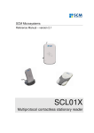
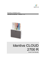
Identive Infrastructure Reference Manual – version 1.03 Identive CLOUD 2700 R Smart Card Reader Reference manual Identive CLOUD 2700 R Smart Card Reader © Identive GmbH Oskar-Messter-Strasse, 13 85737 Ismaning Germany Phone +49 89 9595 5000 • Fax +49 89 9595 5555 Document history Date Version Description of change 08/08/2012 1.01 Initial Version 10/01/2013 1.02 Minor rework 22/02/2013 1.03 Minor corrections Contact information www.identive-group.com/en/products-and-solutions/identification-products/desktop-readersterminals/contact-desktop-readers For sales information, please email [email protected] Table of Contents 1. 2. 3. Legal information ................................................................................................................... 6 1.1. Disclaimers ..................................................................................................................... 6 1.2. Licenses ......................................................................................................................... 6 1.3. Trademarks .................................................................................................................... 6 Introduction to the manual ..................................................................................................... 7 2.1. Objective of the manual ................................................................................................. 7 2.2. Target audience ............................................................................................................. 7 2.3. Product version corresponding to the manual ............................................................... 7 2.4. Definition of various terms and acronyms ...................................................................... 8 2.5. References ..................................................................................................................... 9 2.6. Conventions ................................................................................................................. 10 General information about CLOUD 2700 R ........................................................................ 11 3.1. CLOUD 2700 R key benefits ........................................................................................ 11 3.2. CLOUD 2700 R key features ....................................................................................... 11 3.3. CLOUD 2700 R ordering information ........................................................................... 12 3.4. CLOUD 2700 R customization options ........................................................................ 12 Applications ............................................................................................................................. 13 3.4.1. 3.4.2. 4. General ................................................................................................................. 13 Applications provided by Identive ......................................................................... 13 CLOUD 2700 R characteristics ........................................................................................... 14 4.1. CLOUD 2700 R high level architecture ........................................................................ 14 4.1.1. Block diagram ....................................................................................................... 14 4.1.2. Software architecture ............................................................................................ 15 4.2. Quick reference data .................................................................................................... 16 4.2.1. 4.2.2. 4.2.3. 5. CLOUD 2700 R dimensions.................................................................................. 16 LED behavior ........................................................................................................ 17 Other data ............................................................................................................. 17 4.2.3.1. General ...................................................................................................................... 17 4.2.3.2. USB ........................................................................................................................... 17 4.2.3.3. Card interface ........................................................................................................... 18 Software modules ................................................................................................................ 19 5.1. Installation .................................................................................................................... 19 5.2. Utilities .......................................................................................................................... 19 5.3. Driver ............................................................................................................................ 19 5.3.1. CLOUD 2700 R listing........................................................................................... 19 5.3.2. Supported operating systems ............................................................................... 20 5.4. CT-API.......................................................................................................................... 20 5.5. MCard-API.................................................................................................................... 20 5.6. Firmware ...................................................................................................................... 21 5.6.1. 5.6.1.1. CCID transport protocol ........................................................................................ 21 CCID class requests supported ................................................................................. 21 6. 5.6.1.2. CCID messages supported ........................................................................................ 21 5.6.1.3. CCID Error Codes ...................................................................................................... 21 Commands description ........................................................................................................ 23 6.1. Escape commands for the CLOUD 2700 R ................................................................. 23 6.1.1. 6.1.2. 7. Sending Escape commands to CLOUD 2700 R ................................................... 23 Escape command codes....................................................................................... 24 6.1.2.1. READER_SETMODE ................................................................................................ 25 6.1.2.2. READER_GETMODE ................................................................................................ 25 6.1.2.3. CONTACT_GET_SET_POWER_UP_SEQUENCE ................................................... 26 6.1.2.4. CONTACT_EMV_LOOPBACK .................................................................................. 27 6.1.2.5. CONTACT_EMV_SINGLEMODE .............................................................................. 28 6.1.2.6. CONTACT_APDU_TRANSFER ................................................................................ 28 6.1.2.7. CONTACT_CONTROL_PPS ..................................................................................... 29 6.1.2.8. CONTACT_EXCHANGE_RAW ................................................................................. 29 6.1.2.9. READER_GET_IFDTYPE ......................................................................................... 30 6.1.2.10. READER_LED_CONTROL........................................................................................ 30 6.1.2.11. READER_LED_CONTROL_BY_FW ......................................................................... 31 6.1.2.12. READER_GET_INFO_EXTENDED ........................................................................... 32 6.1.2.13. CONTACT_GET_SET_CLK_FREQUENCY .............................................................. 33 6.1.2.14. CONTACT_GET_SET_ETU ...................................................................................... 34 6.1.2.15. CONTACT_GET_SET_WAITTIME ............................................................................ 35 6.1.2.16. CONTACT_GET_SET_GUARDTIME ........................................................................ 36 6.1.2.17. CONTACT_GET_SET_MCARD_TIMEOUT .............................................................. 37 6.1.2.18. CONTACT_CONTROL_ATR_VALIDATION .............................................................. 38 Annexes............................................................................................................................... 39 7.1. A – Status words table ................................................................................................. 39 7.2. Annex B – Sample code using Escape commands through Escape IOCTL ............... 40 7.3. Annex C – Mechanical drawings .................................................................................. 42 7.3.1. 7.3.2. 7.3.3. 7.3.4. Top Casing ............................................................................................................ 42 Bottom Casing ...................................................................................................... 43 Stand plate ............................................................................................................ 44 Stand socket ......................................................................................................... 45 CLOUD 2700 R REFERENCE MANUAL 1. Legal information 1.1. Disclaimers The content published in this document is believed to be accurate. Identive does not, however, provide any representation or warranty regarding the accuracy or completeness of its content and regarding the consequences of the use of information contained herein. If this document has the status “Draft”, its content is still under internal review and yet to be formally validated. Identive reserves the right to change the content of this document without prior notice. The content of this document supersedes the content of previous versions of the same document. The document may contain application descriptions and/or source code examples, which are for illustrative purposes only. Identive gives no representation or warranty that such descriptions or examples are suitable for the application that the reader may want to use them for. Should you notice problems with the provided documentation, please provide your feedback to [email protected]. 1.2. Licenses If the document contains source code examples, they are provided for illustrative purposes only and subject to the following restrictions: You MAY at your own risk use or modify the source code provided in the document in applications you may develop. You MAY distribute those applications ONLY in form of compiled applications. You MAY NOT copy or distribute parts of or the entire source code without prior written consent from Identive. You MAY NOT combine or distribute the source code provided with Open Source Software or with software developed using Open Source Software in a manner that subjects the source code or any portion thereof to any license obligations of such Open Source Software. If the document contains technical drawings related to Identive products, they are provided for documentation purposes only. Identive does not grant you any license to its designs. 1.3. Trademarks Windows is a trademark of Microsoft Corporation. 6 CLOUD 2700 R REFERENCE MANUAL 2. Introduction to the manual 2.1. Objective of the manual This manual provides an overview of the hardware and software features of the CLOUD 2700 R smart card reader. This manual describes in details interfaces and supported commands available for developers using CLOUD 2700 R in their applications. 2.2. Target audience This document describes the technical implementation of CLOUD 2700 R. The manual targets software developers. It assumes knowledge about ISO/IEC 7816 and commonly used engineering terms. Should you have questions, you may send them to [email protected] . 2.3. Product version corresponding to the manual Item Version Hardware 0.3 Firmware 1.0 7 CLOUD 2700 R REFERENCE MANUAL 2.4. 8 Definition of various terms and acronyms Term Expansion APDU ATR Byte CCID CID LED NA NAD Nibble Application Protocol Data Unit Answer to Reset, defined in ISO/IEC 7816 Group of 8 bits Chip Card Interface Device Card Identifier Light emitting diode Not applicable Node Address Group of 4 bits. 1 digit of the hexadecimal representation of a byte. Example: 0xA3 is represented in binary as (10100011)b. The least significant nibble is 0x3 or (0011)b and the most significant nibble is 0xA or (1010)b Personal Computer/Smart Card: software interface to communicate between a PC and a smart card Product ID Reserved for future use Universal Serial Bus Vendor ID Binary notation of a number x, y, z 0,1 The byte value YY is represented in hexadecimal PC/SC PID RFU USB VID (xyz)b 0xYY CLOUD 2700 R REFERENCE MANUAL 2.5. 9 References Doc ref in the manual Description Issuer ISO/IEC 7816-3 Identification cards — Integrated circuit cards — Part 3: Cards with contacts — Electrical interface and transmission protocols Identification cards - Integrated circuit(s) cards with contacts Part 4: Interindustry commands for interchange ISO/IEC 7816-4: 2005 (E) Interoperability Specification for ICCs and Personal Computer Systems v2.01 Specification for Integrated Circuit(s) Cards Interface Devices 1.1 Universal Serial Bus Specification 2.0 ISO / IEC ISO/IEC 7816-4 PC/SC CCID USB ISO / IEC PC/SC Workgroup USB-IF USB-IF CLOUD 2700 R REFERENCE MANUAL 2.6. 10 Conventions Bits are represented by lower case ‘b’ where followed by a numbering digit. Bytes are represented by upper case ‘B’ where followed by a numbering digit. Bit number 5 b7 b6 Bit number 0 b5 b4 b3 Most significant nibble b2 b1 b0 Least significant nibble 1 Byte = 8 bits = 2 nibbles Byte number 2 B0 B1 Byte number 11 B2 B3 B4 B5 B6 B7 String of 12 bytes Example: 163 decimal number is represented in hexadecimal as 0xA3 in binary as (10100011)b The least significant nibble of 0xA3 is 0x3 in hexadecimal (0011)b in binary The most significant nibble of =xA3 is 0xA in hexadecimal (1010)b in binary B8 B9 B10 B11 CLOUD 2700 R REFERENCE MANUAL 11 3. General information about CLOUD 2700 R 3.1. CLOUD 2700 R key benefits With its combination of a modern slim design and its state of the art feature set, CLOUD 2700 R is the perfect desktop reader choice for environments where smart card support is required. Such environments may be corporates or authorities where use applications like network log-in, Windows authentication & Single Sign-On are implemented. As for all Identive products, CLOUD 2700 R is designed to offer best in class interoperability. 3.2. CLOUD 2700 R key features ISO/IEC 7816 compliant smart card reader PC/SC v2.0 compliant Unique serial number which enables that CLOUD 2700 R can be plugged into any USB slot on a PC without having to re-install the driver. CLOUD 2700 R REFERENCE MANUAL 3.3. CLOUD 2700 R ordering information Item Part number CLOUD 2700 R 905369 Standing Base Kit 905418 CLOUD 2700 R with pre-assembled standing base kit 905369-1912 3.4. 12 CLOUD 2700 R customization options Upon request and based on a minimum order quantity, Identive can customize: The color of the casing The logo The product label The USB strings Terms and conditions apply, please contact your local Identive representative or send an email to [email protected]. CLOUD 2700 R REFERENCE MANUAL 13 Applications 3.4.1. General CLOUD 2700 R is a transparent reader designed to interface a personal computer host supporting PC/SC interface with smart cards according to ISO/IEC 7816 as well as synchronous memory cards like CAC and PKI cards, banking cards and health insurance cards. USB link PC/SC interface Smartcard contacts ISO7816 ` CLOUD 2700 R Network Host CLOUD 2700 R Application logic Interface device Tokens Application logic + User personal data for given set of applications CLOUD 2700 R itself handles the communication protocol but not the application related to the token. The application-specific logic has to be implemented by software developers on the host. 3.4.2. Applications provided by Identive Identive provides a few applications for development and evaluation purposes that can function with CLOUD 2700 R. There are some tools provided; here is one of them: Smart card commander version 1.3 provides capabilities to identify most commonly used cards in the field and display the content of them as well as scripting functionality which can be very useful for developers to develop and debug their applications. Identive does not provide PKI or CAC applications. CLOUD 2700 R REFERENCE MANUAL 14 4. CLOUD 2700 R characteristics 4.1. CLOUD 2700 R high level architecture 4.1.1. Block diagram The link between CLOUD 2700 R and the host to which it is connected is the USB interface providing both the power and the communication channel. ISO7816 contact smart card interface To host Device controller Mask ROM controller LED The CLOUD 2700 R device controller has several interfaces available. In the CLOUD 2700 R implementation 2 peripherals are connected to the device controller: LED for reader status indication A smart card interface The µController contains the firmware developed by Identive to handle all the ISO/IEC 7816 contact protocol and the PC/SC communication protocol with the host. CLOUD 2700 R REFERENCE MANUAL 15 4.1.2. Software architecture Applications can interface with the driver directly through the PC/SC interface. PC/SC Layer Driver - Contact Smart Card Reader FIRMWARE LAYER (CCID-API) T= 0 / T= 1 CLOUD 2700 R Reader ICC The CLOUD 2700 R leverages a PC/SC CCID driver that is freely available for all supported operating systems (Windows, MacOSX and Linux). With current Windows versions (starting with Windows Vista) and MacOSX, this driver is already included in the basic installation. With the diverse Linux derivatives, there may be distribution specific drivers that should get installed using the install mechanism of the used distribution. If there is none, the driver may always be downloaded from the webpage of the maintainer, Ludovic Rousseau, https://alioth.debian.org/frs/?group_id=30105. CLOUD 2700 R REFERENCE MANUAL 4.2. 16 Quick reference data 4.2.1. CLOUD 2700 R dimensions Item Characteristic Weight External dimensions Cable length Default color Value 66g 204g with Standing Base Kit 70x60x16 mm 70x63x62 mm with Standing Base Kit 1.5 meter long with USB type A connector white and cool grey CLOUD 2700 R Default label Drawing with dimensions of the CLOUD 2700 R can be found in annex. CLOUD 2700 R REFERENCE MANUAL 17 4.2.2. LED behavior CLOUD 2700 R is equipped with a green LED. Its behavior is described in the table below. CLOUD 2700 R states LED Indication Reader powered, card out Reader powered, card in but not powered Card powered OFF OFF ON Blinking (500ms ON/500ms OFF) Blinking (100ms ON/100ms OFF Card access error condition 4.2.3. Other data 4.2.3.1. General Parameter Clock of the device controller API Operating temperature range Operating humidity range Certifications Value/Description 48 MHz PC/SC 2.0 0º to 50ºC Up to 95%RH non condensing USB CE UL FCC VCCI WEEE RoHS2 REACH WHQL EMV-L1 Listed in GSA APL 4.2.3.2. USB Parameter DC characteristics USB specification USB Speed Device Class PID VID Value/Description Low bus powered (CLOUD 2700 R draws power from USB bus) Voltage: 5V Max. Current : 6mA + current consumed by an inserted card Suspend current : 500uA USB 2.0 FS device Full Speed Device (12Mbit/s) CCID 0x5810 0x04E6 CLOUD 2700 R REFERENCE MANUAL 4.2.3.3. Card interface Parameter Smart card operating frequency Maximum supported card baud-rate Cards supported ISO/IEC 7816 compliant EMV 4.2 compliant CT-API compliant Number of slots Ejection mechanism Value/Description up to 16MHz 600Kbps Class A, B and C asynchronous smart cards (T=0, T=1) Synchronous smart cards (2wire, 3wire, I²C) Yes Yes Yes Single smart card slot Manual 18 CLOUD 2700 R REFERENCE MANUAL 19 5. Software modules 5.1. Installation On Operating Systems with a PC/SC CCID driver preinstalled, no installation is necessary. Where there’s no PC/SC CCID driver preinstalled (Linux systems) the driver has to be installed using distribution specific measures or installed using the available source packages. 5.2. Utilities The following utilities are available: A tool for testing the resource manager A tool called PC/SC Diag capable of providing basic information about the reader and a card through PC/SC stack Operating systems supported by the tools: 5.3. Windows 2003 Server (32 & 64 bit) Windows XP (32 & 64 bit) Windows Vista (32 & 64 bit) Windows Server 2008 (32 & 64 bit) Windows 7 MacOS X Linux Driver 5.3.1. CLOUD 2700 R listing CLOUD 2700 R is listed by PC/SC applications as Identive CLOUD 2700 R Smart Card Reader CLOUD 2700 R uses the PC/SC CCID class driver readily available for all the supported operating systems. On Windows XP systems, this driver is not preinstalled and has got to be loaded from Windows Update. The Hardware Wizard has got be allowed to load the driver from the internet for that purpose if it is not already present on the system (first time installation). Starting with Windows Vista, the OS does have the driver preinstalled, so no additional driver installation is necessary. MacOSX systems do have the PC/SC CCID driver preinstalled. On Linux systems, the distribution specific installation mechanism should be used. CLOUD 2700 R REFERENCE MANUAL 20 5.3.2. Supported operating systems Windows 2003 Server (32 & 64 bit) 5.4. Windows XP (32 & 64 bit) Windows Vista (32 & 64 bit) Windows Server 2008 (32 & 64 bit) Windows 7 Windows 8 MacOS X Linux (32 & 64 bit) CT-API A CT-API interface that mostly is used in German banking applications and in conjunction with health insurance cards, is available for the reader. 5.5. MCard-API With this proprietary Identive API, it is possible to access a vast majority of synchronous memory cards. Cards supported are: SLE4404 SLE4428 SLE4432 SLE4436 SLE6636 SLE4442 SLE5532 SLE5536 SLE5542 AT24C01ASC AT24C02SC AT24C04SC AT24C08SC AT24C16SC AT24C32SC AT24C64SC AT24C128SC AT24C256SC AT24C512SC AT88SC153 AT88SC1608 ST14C02 CLOUD 2700 R REFERENCE MANUAL 5.6. 21 Firmware 5.6.1. CCID transport protocol CLOUD 2700 R implements a transport protocol that is compliant with USB Device Class: Smart Card CCID Specification for Integrated Circuit(s) Cards Interface Devices Revision 1.10. This paragraph describes the CCID specification features that are implemented. 5.6.1.1. CCID class requests supported Abort 5.6.1.2. CCID messages supported The following CCID messages are supported for the contact interface when received through bulk-out endpoint. PC_to_RDR_IccPowerOn PC_to_RDR_IccPowerOff PC_to_RDR_GetSlotStatus PC_to_RDR_XfrBlock PC_to_RDR_GetParameters PC_to_RDR_SetParameters PC_to_RDR_Escape PC_to_RDR_Abort PC_to_RDR_NotifySlotChange PC_to_RDR_ResetParameters PC_to_RDR_T0APDU PC_to_RDR_SetDatarateAndClockFrequency 5.6.1.3. CCID Error Codes Extensive error codes are reported on many conditions during all CCID responses. Most of the error messages are reported by the CCID appropriately. Some of the main error codes for the contact interface are: HW_ERROR XFR_PARITY_ERROR ICC_PROTOCOL_NOT_SUPPORTED BAD_ATR_TS BAD_ATR_TCK ICC_MUTE CMD_ABORTED Command not supported CLOUD 2700 R REFERENCE MANUAL 22 The following sub-sections discuss when and why these error codes are returned: 5.6.1.3.1. HW_ERROR This error code is returned when a hardware short circuit condition is detected, during application of power to the card or if any other internal hardware error is detected. 5.6.1.3.2. XFR_PARITY_ERROR This error code is returned when a parity error condition is detected. This error will be reported in the response to a PC_to_RDR_XfrBlock message. 5.6.1.3.3. ICC_PROTOCOL_NOT_SUPPORTED This error code is returned if the card is signaling to use a protocol other than T=0 or T=1 in its ATR. 5.6.1.3.4. BAD_ATR_TS This error code is returned if the initial character of the ATR contains invalid data. 5.6.1.3.5. BAD_ATR_TCK This error code is returned if the check character of the ATR contains is invalid. 5.6.1.3.6. ICC_MUTE This error code is returned when the card does not respond until the reader time out occurs. This error will be reported in the response to PC_to_RDR_XfrBlock message and PC_to_RDR_IccPowerOn messages. 5.6.1.3.7. CMD_ABORTED This error code is returned if the command issued has been aborted by the control pipe. 5.6.1.3.8. Command not supported This error would be returned, if the command would not be supported by the reader. CLOUD 2700 R REFERENCE MANUAL 23 6. Commands description 6.1. Escape commands for the CLOUD 2700 R 6.1.1. Sending Escape commands to CLOUD 2700 R A developer can use the following method to send Escape commands to CLOUD 2700 R SCardControl method defined in PC/SC API In Windows, in order to be able to send Escape commands to the CLOUD 2700 R, the feature has got to be enabled by setting a REG_DWORD value named ‘EscapeCommandEnable’ in the registry to a value of ‘1’. For Windows XP and Windows Vista, the key to hold the value would be HKEY_LOCAL_MACHINE\SYSTEM\CurrentControlSet\Enum\USB\VID_04E6&PID_58 10\ Device-Instance-xxxx \Device Parameters For Windows 7 and Windows 8, that would be HKEY_LOCAL_MACHINE\SYSTEM\CurrentControlSet\Enum\USB\VID_04E6&PID_58 10\Device-Instance-xxxx \Device Parameters\WUDFUsbccidDriver Device-Instance-xxxx has got to be equal to the serial number of the reader used, so this modification has got to be made for every physical reader intended to be used on the machine in question. The reader has got to be plugged in at least once for the mentioned key to exist and the driver has got to be restarted for this setting to take effect. (Unplug and re-plug the reader). To be able to work with synchronous memory cards using our MCard API, the same setting will have to be established. See appendix B for some sample code sending Escape commands to the reader. CLOUD 2700 R REFERENCE MANUAL 24 6.1.2. Escape command codes Escape commands can be used by an application to configure CLOUD 2700 R to function in a mode that is not its default configured mode or to get specific information. To put the CLOUD 2700 R back into its default mode, it either has to be unplugged and plugged again or the application can send the same Escape command again. The following Escape commands are supported by CLOUD 2700 R Escape command Code READER_SETMODE 0x01 READER_GETMODE 0x02 CONTACT_GET_SET_POWERUPSEQUENCE 0x04 CONTACT_EMV_LOOPBACK 0x05 CONTACT_EMV_SINGLEMODE 0x06 CONTACT_APDU_TRANSFER 0x08 CONTACT_CONTROL_PPS 0x0F CONTACT_EXCHANGE_RAW 0x10 READER_GETIFDTYPE 0x12 READER_LED_CONTROL 0x19 READER_LED_CONTROL_BY_FW 0xB2 READER_GETINFO_EXTENDED 0X1E CONTACT_GET_SET_CLK_FREQUENCY 0x1F CONTACT_GET_SET_ETU 0x80 CONTACT_GET_SET_WAITTIME 0x81 CONTACT_GET_SET_GUARDTIME 0x82 CONTACT_GET_SET_MCARD_TIMEOUT 0x85 CONTACT_CONTROL_ATR_VALIDATION 0x88 CLOUD 2700 R REFERENCE MANUAL 25 6.1.2.1. READER_SETMODE This Escape command sets the current mode of the reader. Applications may call this function, to set the desired mode. Typically, this call is used to switch between the ISO/IEC 7816, EMV and memory card operations. Upon power on, the reader will reset to the default ISO/IEC 7816 mode. Input: The first byte of the input buffer contains the Escape code value and the second one will contain the value for the desired mode of operation. The output buffer field will be NULL. Byte0 Byte1 Escape code (0x01) Mode Following table gives the value of modes as interpreted by the firmware: Mode Value Remarks ISO 0x00 ISO/IEC 7816 mode EMV 0x01 EMV Synchronous 0x02 memory card mode (Synchronous) ISO mode uses APDU mode of data transfer and is used for normal operations. This is the default mode of the reader on power up. EMV mode also uses APDU mode of data transfer and is used for EMV test purposes. This mode has more stringent checks for smart card detection and communication as per EMV4.2 spec. Synchronous mode is used for communicating only with memory cards. Any other value sent as mode is invalid. The output buffer is Output buffer NULL 6.1.2.2. READER_GETMODE This Escape command may be used to retrieve the current mode of the reader. The input buffer is Byte0 Escape code(0x02) Output: Current active reader mode will be returned as a BYTE value. CLOUD 2700 R REFERENCE MANUAL 26 Following table gives the value of modes as interpreted by reader firmware Mode Value Remarks ISO 0x00 ISO/IEC 7816 mode EMV 0x01 EMV Synchronous 0x02 memory card mode (synchronous) 6.1.2.3. CONTACT_GET_SET_POWER_UP_SEQUENCE This Escape command is used by the application/driver to get/set the following parameters: Smart card Power-on sequence Delay between successive Activation retries Enable/Disable any Voltage Class As soon as card insertion is detected and power on message is received from the host, the firmware will start activation with the configured voltage sequence. If the activation fails, it will wait for the configured activation delay and then retry with the next enabled voltage class. If power up succeeds at an operating voltage, the firmware will continue card communication at that voltage. If power up fails in all the enabled operating voltages, then the firmware will report an error. The default power-up sequence would be A – B – C. Input: The first byte of the input buffer contains the Escape code. The next byte contains the function to be performed. Third byte contains the parameter for the function. Byte0 Byte1 Value Escape code(0x04) Byte2 Description Starts with Class C voltage. (1.8V – 3V – 5V order) - Starts with Class A voltage. (5V – 3V – 1.8V order) - 0x08 Time delay between resets Delay value in milliseconds 0x09 Enable/Disable Class Bit Map of all Voltage Classes 0x00 0x01 a Voltage [Bit0 – Class A; Bit1 – Class B; Bit2 – Class C] Set bit to enable the Voltage class Clear bit to disable the Voltage class 0xFE Retrieves values all the above - 0xFF Retrieves the current Power up sequence - CLOUD 2700 R REFERENCE MANUAL 27 Output: For retrieving all settings (0xFE), the output will be the following: Byte0 Value 0x00 0x01 Byte 1 Byte2 Time delay between resets in milliseconds Bit Map of all Voltage Classes Description Starts with Class C voltage. (1.8V – 3V – 5V order) Starts with Class A voltage. (5V – 3V – 1.8V order) [Bit0 – Class A; Bit1 – Class B; Bit2 – Class C] For retrieving current power up sequence (0xFF), the output will be: Byte0 Value Description Starts with Class C voltage. (1.8V – 3V – 5V order) 0x00 Starts with Class A voltage. (5V – 3V – 1.8V order) 0x01 Example: retrieve all the current settings: DataIn = 04 FE DataOut: 01 0A 07 (3 bytes) 00: 0A: 07: Starting with Class A 10ms delay between resets Class A, B, and C enabled 6.1.2.4. CONTACT_EMV_LOOPBACK This Escape command lets the host force the firmware to perform an EMV Loop-back application. The input buffer is Byte0 Escape code(0x05) The output buffer is Output buffer NULL CLOUD 2700 R REFERENCE MANUAL 28 6.1.2.5. CONTACT_EMV_SINGLEMODE This Escape command lets the host perform a one-shot EMV Loop-back application as specified in the EMV Level 1 Testing Requirements document. The input buffer is Byte0 Escape code(0x06) The output buffer is Output buffer NULL 6.1.2.6. CONTACT_APDU_TRANSFER This Escape command exchanges a short APDU with the smart card. The user has to ensure that a card is inserted and powered before issuing this Escape command. This Escape command mostly is used by the MCard API to access synchronous memory cards. Input: The input buffer contains the Escape code value followed by the short APDU to be sent to the card. Byte0 Byte1 onwards Escape code(0x08) Short APDU to be sent to card The output buffer contains the response APDU. Output buffer Response APDU CLOUD 2700 R REFERENCE MANUAL 29 6.1.2.7. CONTACT_CONTROL_PPS This Escape command enables or disables the PPS done by the firmware/device for smart cards. This setting will take effect from the next card connect and remains effective till it is changed again or the next Reader power on. Default mode is PPS enabled. Input: The first byte of input buffer contains the Escape code and the following byte, if 1 disables the PPS and if 0 enables the PPS. Byte0 Byte1 Escape code(0x0F) PPS control byte (1-DISABLES PPS, 0-ENABLES PPS) The output buffer is Output buffer NULL 6.1.2.8. CONTACT_EXCHANGE_RAW This Escape command can be used to perform raw exchange of data with the card. The user must ensure that a card is inserted and powered on before issuing this Escape command. The Card is deactivated upon any reception error. Input: The input buffer for this command will contain the Escape code, low byte of the length of data to be sent, high byte of length of data to be sent, low byte of the length of expected data, high byte of length of expected data and the command. Byte0 Byte1 Byte2 Byte3 Byte4 Byte 5 onwards Escape code(0x10) LSB of send length MSB of send length LSB of expected length MSB of expected length Raw data to the card Output: Output buffer Response APDU CLOUD 2700 R REFERENCE MANUAL 30 6.1.2.9. READER_GET_IFDTYPE This Escape command is used to get the current IFD type from the reader. Input: The first byte of the input buffer contains the Escape code. Byte0 Escape code(0x12) Output: The reader returns the PID of the firmware which can be used to identify the reader. PID value B0 B1 0x10 0x58 Description USB PID of Identive CLOUD 2700 R smart card Reader 6.1.2.10. READER_LED_CONTROL This Escape command may be used to toggle the LED state. LED control by firmware should be disabled using the Escape command READER_LED_CONTROL_BY_FW to see proper LED change while using this IOCTL else the LED state will be overwritten by the FW LED behavior. Input: The first byte of the input buffer contains the Escape code, followed by LED number always set to 0 (just one LED) and then the desired LED state. Byte0 Byte 1 Byte2 Escape code(0x19) LED number (0 GREEN) LED state (0-OFF, 1-ON) Output: Output buffer NULL CLOUD 2700 R REFERENCE MANUAL 31 6.1.2.11. READER_LED_CONTROL_BY_FW This command is used to enable/disable LED control by firmware. Default setting is: LED is controlled by firmware. Input: The first byte of the input buffer contains the Escape code. The second byte specifies if LED control by the firmware should be disabled or enabled. The output buffer is NULL. Byte0 Byte1 Value Description Escape code(0xB2) 0 Enable LED Control by firmware 1 Disable LED Control by firmware Get State FF 0 -- LED control by firmware enabled 1 -- LED control by firmware disabled Output: No response is returned for set state. For Get State 1 byte response is received. Output buffer NULL or current state CLOUD 2700 R REFERENCE MANUAL 32 6.1.2.12. READER_GET_INFO_EXTENDED This Escape command may be used to retrieve extended information about the reader and supported features. Input: The first byte of the input buffer contains the Escape code. Byte0 Escape code(0x1E) Output: The firmware returns data as per structure SCARD_READER_GETINFO_PARAMS_EX mentioned below. This Escape command is used to get the firmware version, reader capabilities, and Unicode serial number of the reader. Field Size in Bytes Field Name Field Description 1 byMajorVersion Major Version in BCD 1 byMinorVersion Minor Version in BCD 1 bySupportedModes Total no of supported modes in the reader Default value Based on current firmware version 0x03 (ISO, EMV and MCard modes) Protocols supported by the Reader Bit 0 – T0 2 2 wSupportedProtocols winputDevice Bit 1 – T1 IO_DEV_NONE IO_DEV_KEYPAD IO_DEV_BIOMETRIC 0x0300 (LSB first) 0x00 0x01 0x02 0x0000(LSB first) 1 byPersonality Reader Personality (Not Used ) 0x00 1 byMaxSlots Maximum number of slots 0x01 (Single slot device) 1 bySerialNoLength Serial number length 0x1C 28 abySerialNumber [28] Unicode serial number Reader serial number(MSB first) DataIn = 1E DataOut: 01 00 03 03 00 00 00 00 01 1C 35 00 33 00 36 00 39 00 31 00 33 00 30 00 31 00 32 00 30 00 30 00 30 00 36 00 32 00 (38 bytes) CLOUD 2700 R REFERENCE MANUAL 33 6.1.2.13. CONTACT_GET_SET_CLK_FREQUENCY In case when an application wants to get or set the smart card clock frequency, this Escape command is used to instruct the reader to change the clock or to get the current Clock divisor used. Once set, the change in frequency will take effect immediately. Default divisor value is 10, that is 4.8MHz. Input: The first byte of the input buffer will contain the Escape code; the next byte will contain the clock divisor value to set clock frequency or 0xFF to get clock frequency. Byte0 Byte1 Escape code(0x1F) Value Description Clock divisor The value to be Set register 0xFF Get current Clock divisor value in the smart card CLK divisor Output: Set clock frequency: None Get clock frequency: One byte value indicating the current Clock divisor. Output buffer NULL or current divisor Clock Divisor values: DIVISOR VALUE SCCLK Frequency 12 4 MHz 10 4.8 MHz 8 6 MHz 7 6.8 MHz 6 8 MHz 5 9.6 MHz 4 12 MHz 3 16 MHz DataIn = 1F FF DataOut: 0A (1 byte) CLOUD 2700 R REFERENCE MANUAL 34 6.1.2.14. CONTACT_GET_SET_ETU This Escape command is be used by the HOST to get/set the current ETU for smart cards. Once set, the new ETU value will take effect immediately. Input: The input buffer contains the Escape followed by an 8 bit GET/SET identifier. For SET ETU, a DWORD specifying the value to be set is following. Byte0 Escape code(0x80) Byte1 Byte2 Byte5 Description Wait time 0x01 SET ETU BIT31BIT24 BIT23BIT16 BIT15BIT8 BIT7BIT0 0x00 GET ETU - - - - For both Set and Get ETU, the output will be the following. Byte1 Byte2 Byte3 ETU value BIT31-BIT24 Byte4 Value Output: Byte0 Byte3 BIT23-BIT16 BIT15-BIT8 DataIn = 80 00 DataOut: 00 00 01 40 (4 bytes) BIT7-BIT0 CLOUD 2700 R REFERENCE MANUAL 35 6.1.2.15. CONTACT_GET_SET_WAITTIME This Escape command is used to get/set the Character/Block Waiting Time for smart cards. The wait time is specified in terms of ETU. Once set, the new Wait time will take effect from the next card communication. Input: The input buffer contains the Escape code followed by an 8 bit GET/SET identifier, an 8 bit Wait time identifier and a 32 bit Wait time value. BWT must be specified in units of 1.25ms and CWT in units of ETU. Byte0 Escape code(0x81) Byte1 Byte2 Byte3 Value Description Value Description 0x01 SET time 0x00 CWT 0x01 BWT 0x00 CWT 0x01 BWT 0x00 GET time Wait Wait Output: For both Get/Set Wait time, the output will be the following. Byte0 Byte1 Byte2 Byte3 Wait time in ETU BIT31-BIT24 BIT23-BIT16 BIT15-BIT8 DataIn = 81 00 01 DataOut: 00 00 03 5D (4 bytes) BIT7-BIT0 Byte4 Byte5 Byte6 Wait time in ETU BIT31BIT24 BIT23BIT16 BIT15BIT8 BIT7BIT0 - - - - CLOUD 2700 R REFERENCE MANUAL 36 6.1.2.16. CONTACT_GET_SET_GUARDTIME This Escape command is used to get/set the Character/Block Guard Time of the reader. The guard time is specified in terms of ETU. Once set, the new Guard time will take effect immediately. Input: The input buffer contains the Escape code followed by an 8 bit GET/SET identifier, an 8 bit guard time identifier and a 32 bit guard time value in ETU. Byte0 Byte1 Escape code(0x82) Byte2 Byte3 Value Description Value Description 0x01 SET Guard time 0x00 CGT 0x01 BGT 0x00 CGT 0x01 BGT 0x00 GET Guard time Byte4 BIT31BIT24 BIT23BIT16 BIT15BIT8 BIT7BIT0 - - - - For Get/Set guard time, the output will be the Character/Block Guard Time value. Byte1 Byte2 Byte3 Character Guard time in ETU BIT31-BIT24 BIT23-BIT16 BIT15-BIT8 DataIn = 82 00 01 DataOut: 00 00 00 18 (4 bytes) BIT7-BIT0 Byte6 Guard time in ETU Output: Byte0 Byte5 CLOUD 2700 R REFERENCE MANUAL 37 6.1.2.17. CONTACT_GET_SET_MCARD_TIMEOUT This Escape command is used to get or set the delay which is applied after a Write operation to memory cards. The delay is specified in milliseconds. Input: The first byte of the input buffer will contain the Escape code; the next byte will contain the memory card write delay in seconds. Byte0 Escape code(0x85) Byte1 Value Description 0x01 Delay in milliseconds for memory card Write Any value other than 1 Read the current applied delay for memory card Write Output: Write delay: No response byte Read delay value: A byte value specifying the current delay applied during memory card Write in milliseconds Byte0 Delay in ms DataIn = 85 00 DataOut: 00 (1 byte) CLOUD 2700 R REFERENCE MANUAL 38 6.1.2.18. CONTACT_CONTROL_ATR_VALIDATION This Escape command is used to enable or disable the ATR validation by the firmware in ISO/IEC 7816 mode. In case the card would emit an ATR that is not ISO/IEC 7816 compliant, the card reader may fail to power up the card. In these cases, disabling ATR validation will let you work with the card regardless of ISO conformity of the ATR. By default, ATR validation is enabled. Input: The first byte of the input buffer will contain the Escape code; the next byte will contain the control byte. Byte0 Escape code(0x88) Output: Output buffer NULL Byte1 Value Description 0x00 Enable ATR validation 0x01 Disable ATR validation CLOUD 2700 R REFERENCE MANUAL 7. Annexes 7.1. A – Status words table SW1 SW2 Description 0x90 0x00 NO ERROR 0x67 0x00 LENGTH INCORRECT 0x6D 0x00 INVALID INSTRUCTION BYTE 0x6E 0x00 CLASS NOT SUPPORTED 0x6F 0x00 UNKNOWN COMMAND 0x63 0x00 NO INFORMATION GIVEN 0x65 0x81 MEMORY FAILURE 0x68 0x00 CLASS BYTE INCORRECT 0x6A 0x81 FUNCTION NOT SUPPORTED 0x6B 0x00 WRONG PARAMETER P1-P2 39 CLOUD 2700 R REFERENCE MANUAL 40 Annex B – Sample code using Escape commands through Escape IOCTL 7.2. File Name : CLOUD 2700 R Escape.h #ifndef _CLOUD_2700 R_ESCAPE_H_ #define _CLOUD_2700 R_ESCAPE_H_ #ifdef __cplusplus extern "C" { #endif # pragma pack (1) typedef struct { BYTE byMajorVersion; BYTE byMinorVersion; BYTE bySupportedModes; WORD wSupportedProtocols; WORD winputDevice; BYTE byPersonality; BYTE byMaxSlots; BYTE bySerialNoLength; BYTE abySerialNumber [28]; } ReaderInfoExtended; # pragma pack () #define IOCTL_CCID_ESCAPE SCARD_CTL_CODE (0xDAC) #define #define #define #define #define #define #define #define #define #define #define #define #define #define #define #define #define #define 0x01 0x02 0x04 0x05 0x06 0x08 0x0F 0x10 0x12 0x19 0xB2 0x1E 0x1F 0x80 0x81 0x82 0x85 0x88 READER_SET_MODE READER_GET_MODE CONTACT_GET_SET_POWERUPSEQUENCE CONTACT_EMV_LOOPBACK CONTACT_EMV_SINGLEMODE CONTACT_APDU_TRANSFER CONTACT_CONTROL_PPS CONTACT_EXCHANGE_RAW READER_GETIFDTYPE READER_LED_CONTROL READER_LED_CONTROL_BY_FW READER_GETINFO_EXTENDED CONTACT_GET_SET_CLK_FREQUENCY CONTACT_GET_SET_ETU CONTACT_GET_SET_WAITTIME CONTACT_GET_SET_GUARDTIME CONTACT_GET_SET_MCARD_TIMEOUT CONTACT_CONTROL_ATR_VALIDATION #ifdef __cplusplus } #endif #endif File Name : #include #include #include #include #include #include #include CLOUD 2700 R Escape.c <windows.h> <winbase.h> <stdio.h> <conio.h> "winscard.h" "winerror.h" "CLOUD 2700R Escape.h" VOID main(VOID) { SCARDCONTEXT SCARDHANDLE ReaderInfoExtended ContextHandle; CardHandle; strReaderInfo; CLOUD 2700 R REFERENCE MANUAL BYTE DWORD ULONG char 41 InByte, i; BytesRead, ActiveProtocol; ret; *ReaderName[] = {"Identive CLOUD 2700 R Smart Card Reader 0", NULL}; /*************************************************************************************** *****************/ ContextHandle = -1; ret = SCardEstablishContext(SCARD_SCOPE_USER, NULL, NULL, &ContextHandle); if (ret == SCARD_S_SUCCESS) { ret = SCardConnect( ContextHandle, ReaderName[0], SCARD_SHARE_DIRECT, SCARD_PROTOCOL_UNDEFINED, &CardHandle, &ActiveProtocol); if (ret == SCARD_S_SUCCESS) { InByte = 0x1E; ret = SCardControl( CardHandle, IOCTL_CCID_ESCAPE, &InByte, 1, &strReaderInfo, sizeof(strReaderInfo), &BytesRead); if (SCARD_S_SUCCESS == ret) { printf("major version:\t\t%d%d\n", (strReaderInfo.byMajorVersion & 0xF0)>> 4, (strReaderInfo.byMajorVersion & 0x0F)); printf("minor version:\t\t%d%d\n", (strReaderInfo.byMinorVersion & 0xF0)>> 4, (strReaderInfo.byMinorVersion & 0x0F)); printf("modes:\t\t\t%d\n", strReaderInfo.bySupportedModes); printf("protocols:\t\t%04x\n", strReaderInfo.wSupportedProtocols); printf("input device:\t\t%04x\n", strReaderInfo.winputDevice); printf("personality:\t\t%d\n", strReaderInfo.byPersonality); printf("max slots:\t\t%d\n", strReaderInfo.byMaxSlots); printf("serial no length:\t%d\n", strReaderInfo.bySerialNoLength); printf("serial no:\t\t"); for (i = 0; i < strReaderInfo.bySerialNoLength; i++) printf("%c", strReaderInfo.abySerialNumber[i]); } else { printf("SCardControl failed: %08X\n", ret); } } else { printf("SCardConnect failed: %08X\n", ret); } ret = SCardReleaseContext(ContextHandle); } else { printf("\n SCardEstablishContext failed with %.8lX",ret); } printf("\npress any key to close the test tool\n"); getch(); } CLOUD 2700 R REFERENCE MANUAL 7.3. Annex C – Mechanical drawings 7.3.1. Top Casing 42 CLOUD 2700 R REFERENCE MANUAL 7.3.2. Bottom Casing 43 CLOUD 2700 R REFERENCE MANUAL 7.3.3. Stand plate 44 CLOUD 2700 R REFERENCE MANUAL 7.3.4. Stand socket 45