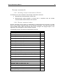
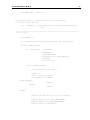
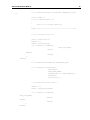
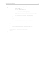
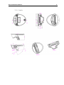
1
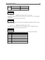
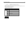
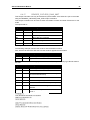
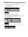
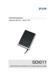
SCM Microsystems Reference Manual – version 2.0 SCL01X Multiprotocol contactless stationary reader Reference manual SCL01X Multiprotocol Contactless Stationary Reader © SCM Microsystems Oskar-Messter-Strasse, 13 85737 Ismaning Germany Phone +49 89 9595 5000 • Fax +49 89 9595 5555 Document history Date Version Description of change 26/10/2010 2.0 Initial version Typo corrections Add the Pass_through command description Manual fro both SCL010 and SCL011 products Contact information http://www.scmmicro.com/products-services/smart-card-readers-terminals/contactless-dualinterface-readers.html For sales information, please email [email protected] Table of Contents 1. Legal information ................................................................................................................... 8 1.1. Disclaimers ..................................................................................................................... 8 1.2. FCC ................................................................................................................................ 8 1.2.1. Section 15.21 Information to user ........................................................................... 8 1.2.2. Section 15.105 (b) ................................................................................................... 8 1.3. Licenses ......................................................................................................................... 8 1.4. 2. 3. Trademarks .................................................................................................................... 9 Introduction to the manual ................................................................................................... 10 2.1. Objective of the manual ............................................................................................... 10 2.2. Target audience ........................................................................................................... 10 2.3. Product version corresponding to the manual ............................................................. 10 2.4. Definition of various terms and acronyms .................................................................... 11 2.5. References ................................................................................................................... 12 2.6. Conventions ................................................................................................................. 13 General information about SCL01X .................................................................................... 14 3.1. SCL01X key benefits .................................................................................................... 14 3.2. SCL01X key features ................................................................................................... 14 3.3. SCL01X ordering information ....................................................................................... 15 3.4. SCL01X customization options .................................................................................... 15 3.5. Contactless communication principles and SCL01X usage recommendations ........... 16 3.5.1. Power supply......................................................................................................... 16 3.5.2. Data exchange ...................................................................................................... 16 3.5.3. Recommendations ................................................................................................ 17 3.6. Applications .................................................................................................................. 18 3.6.1. 3.6.2. 4. General ................................................................................................................. 18 Applications provided by SCM Microsystems ....................................................... 18 SCL01X characteristics ....................................................................................................... 19 4.1. SCL01X high level architecture .................................................................................... 19 4.1.1. Block diagram ....................................................................................................... 19 4.1.2. Software architecture ............................................................................................ 19 4.2. Quick reference data .................................................................................................... 20 4.2.1. 4.2.2. 4.2.3. 5. SCL01X dimensions ............................................................................................. 20 LED behavior ........................................................................................................ 20 Other data ............................................................................................................. 21 Software modules ................................................................................................................ 22 5.1. Installation .................................................................................................................... 22 5.2. Utilities .......................................................................................................................... 22 5.3. Driver ............................................................................................................................ 22 5.3.1. 5.3.2. SCL01X listing ...................................................................................................... 22 Supported operating systems ............................................................................... 22 5.3.3. PC/SC 2.0 compliant ATR .................................................................................... 23 5.4. Firmware ...................................................................................................................... 28 5.4.1. 5.4.2. 6. CCID-like transport protocol.................................................................................. 28 Automatic PPS ...................................................................................................... 29 Commands description ........................................................................................................ 30 6.1. Generic APDU .............................................................................................................. 30 6.1.1. Get UID Command ............................................................................................... 30 6.1.2. Escape command APDU ...................................................................................... 32 6.2. Set of APDU for contactless storage user tokens ........................................................ 33 6.2.1. STORAGE_CARD_CMDS_READ_BINARY ........................................................ 33 6.2.2. STORAGE_CARD_CMDS_WRITE_BINARY ...................................................... 35 6.2.3. STORAGE_CARD_CMDS_LOAD_KEYS ............................................................ 37 6.2.4. STORAGE_CARD_CMDS_AUTHENTICATE ...................................................... 38 6.2.5. STORAGE_CARD_CMDS_VALUE_BLOCK ....................................................... 40 6.3. Set of APDU for ISO/IEC14443-4 user tokens ............................................................ 41 6.3.1. T=CL Command.................................................................................................... 41 6.3.2. T=CL user command ............................................................................................ 42 6.4. Set of APDU defined by SCM Microsystems ............................................................... 43 6.4.1. MIFARE DESFire Commands .............................................................................. 43 6.4.2. Commands for communicating with NFC Forum Tags Type 1 ............................. 43 6.4.3. Commands for communicating with NFC Forum Tags Type 2 ............................. 52 6.4.4. Commands for communication with NFC Forum Tags Type 3 ............................. 52 6.4.5. Commands for communicating with NFC Forum Tags Type 4 ............................. 54 6.4.6. PASS_THROUGH command ............................................................................... 54 Escape commands.................................................................................................................. 56 6.4.7. 6.4.8. 6.4.9. 6.4.10. 6.4.11. 6.4.12. 6.4.13. 6.4.14. 6.4.15. 6.4.16. 6.4.17. 6.4.18. 6.4.19. 6.4.20. 6.4.21. 6.4.22. 6.4.23. 6.4.24. 6.4.25. 6.4.26. 7. Sending escape commands to SCL01X ............................................................... 56 Escape command codes ....................................................................................... 56 READER_GETCARDINFO ................................................................................... 57 READER_LED_CONTROL_BY_FW .................................................................... 57 READER_LEDCONTROL .................................................................................... 57 READER_CNTLESS_GET_ATS_ATQB .............................................................. 58 READER_CNTLESS_GET_TYPE ....................................................................... 58 READER_CNTLESS_SET_TYPE ........................................................................ 59 READER_CNTLESS_RF_SWITCH ..................................................................... 60 READER_CNTLESS_RAW_CFG ........................................................................ 60 READER_CNTLESS_RAW_XMIT ....................................................................... 61 READER_ CNTLESS_DISABLE_PPS ................................................................. 62 READER_CNTLESS_848KBPS ........................................................................... 62 READER_CNTLESS_BAUDRATE ....................................................................... 63 READER_CNTLESS_FORCE_BAUDRATE_PCSC_REV2 ................................ 64 READER_GETPNPPARAMS ............................................................................... 65 READER_GETSLOTINFO.................................................................................... 65 READER_GET_CARD_DETAILS ........................................................................ 66 READER_IS_SCL01x ........................................................................................... 67 READER_SEND_ATTRIB_WITH_INF ................................................................. 68 Annexes ............................................................................................................................... 69 7.1. Annex A – Status words table ...................................................................................... 69 7.2. Annex B – Sample code using escape commands through Escape IOCTL ............... 70 7.3. Annex C – Mechanical drawings .................................................................................. 75 7.3.1. 7.3.2. 7.3.3. Top casing............................................................................................................. 75 Bottom casing ....................................................................................................... 76 Cradle.................................................................................................................... 77 7.3.4. Snap-on card holder ............................................................................................. 78 SCL01X REFERENCE MANUAL 1. Legal information 1.1. Disclaimers The content published in this document is believed to be accurate. SCM Microsystems does not, however, provide any representation or warranty regarding the accuracy or completeness of its content and regarding the consequences of the use of information contained herein. If this document has the status ―Draft‖, its content is still under internal review and yet to be formally validated. SCM Microsystems reserves the right to change the content of this document without prior notice. The content of this document supersedes the content of previous versions of the same document. The document may contain application descriptions and/or source code examples, which are for illustrative purposes only. SCM Microsystems gives no representation or warranty that such descriptions or examples are suitable for the application that the reader may want to use them for. Should you notice problems with the provided documentation, please provide your feedback to [email protected]. 1.2. FCC 1.2.1. Section 15.21 Information to user Changes or modifications not expressly approved by the party responsible for compliance could void the user's authority to operate the equipment 1.2.2. Section 15.105 (b) Note: This equipment has been tested and found to comply with the limits for a Class B digital device, pursuant to part 15 of the FCC Rules. These limits are designed to provide reasonable protection against harmful interference in a residential installation. This equipment generates, uses and can radiate radio frequency energy and, if not installed and used in accordance with the instructions, may cause harmful interference to radio communications. However, there is no guarantee that interference will not occur in a particular installation. If this equipment does cause harmful interference to radio or television reception, which can be determined by turning the equipment off and on, the user is encouraged to try to correct the interference by one or more of the following measures: --Reorient or relocate the receiving antenna. --Increase the separation between the equipment and receiver. --Connect the equipment into an outlet on a circuit different from that to which the receiver is connected. --Consult the dealer or an experienced radio/TV technician for help. 1.3. Licenses If the document contains source code examples, they are provided for illustrative purposes only and subject to the following restrictions: You MAY at your own risk use or modify the source code provided in the document in applications you may develop. You MAY distribute those applications ONLY in form of compiled applications. 8 SCL01X REFERENCE MANUAL You MAY NOT copy or distribute parts of or the entire source code without prior written consent from SCM Microsystems. You MAY NOT combine or distribute the source code provided with Open Source Software or with software developed using Open Source Software in a manner that subjects the source code or any portion thereof to any license obligations of such Open Source Software. If the document contains technical drawings related to SCM Microsystems products, they are provided for documentation purposes only. SCM Microsystems does not grant you any license to its designs. 1.4. Trademarks MIFARE is a registered trademark of NXP Semiconductors BV. FeliCa is a registered trademark of Sony Corporation. Jewel and Topaz are trademarks of Innovision Research and Technology Plc. Windows is a trademark of Microsoft Corporation. 9 SCL01X REFERENCE MANUAL 10 2. Introduction to the manual 2.1. Objective of the manual This manual provides an overview of the hardware and software features of the SCL01X contactless reader, hereafter referred to as ―SCL01X‖. This manual describes in details interfaces and supported commands available for developers using SCL01X in their applications. 2.2. Target audience This document describes the technical implementation of SCL01X. The manual targets software developers. It assumes knowledge about 13.56 MHz contactless technologies like ISO/IEC 14443 and commonly used engineering terms. Should you have questions, you may send them to [email protected] . 2.3. Product version corresponding to the manual This manual is related to the version indicated below, and all further versions. Item Version Hardware 4.4 Firmware 1.09 Windows Driver 5.06 Linux 2.06 MAC 2.06 SCL01X REFERENCE MANUAL 2.4. 11 Definition of various terms and acronyms Term Expansion APDU ATR ATS Byte CCID CID CL DFU DR DS FeliCa™ Application Protocol Data Unit Answer to Reset, defined in ISO7816 Answer to select, defined in ISO/IEC 14443 Group of 8 bits Chip Card Interface Device Card Identifier Contactless Device Firmware Upgrade Divider receive: used to determine the baud rate between the reader to the card Divider send: used to determine the baud rate between the card to the reader Sony contactless technology standardized in ISO18092, technology underlying the NFC Forum tag type 3 Innovision contactless technology, technology underlying the NFC Forum tag type 1 Light emitting diode The ISO14443 Type A with extensions for security (NXP) Not applicable Node Address NFC Data Exchange Format: data structure defined by the NFC Forum for NFC Forum tags. Near Field Communication Group of 4 bits. 1 digit of the hexadecimal representation of a byte. Example: 0xA3 is represented in binary as (10100011)b. The least significant nibble is 0x3 or (0011)b and the most significant nibble is 0xA or (1010)b Peer - to - Peer Proximity Coupling Device Personal Computer/Smart Card: software interface to communicate between a PC and a smart card Proximity Integrated Chip Card Product ID Distance coverage till ~10 cm. Pseudo unique PICC identifier Reserved for future use Radio Frequency Smart card reader controller ASIC from SCM Microsystems Universal Serial Bus Vendor ID Binary notation of a number x, y, z 0,1 The byte value YY is represented in hexadecimal Jewel/Topaz LED MIFARE NA NAD NDEF NFC Nibble P2P PCD PC/SC PICC PID Proximity PUPI RFU RF STCIII USB VID (xyz)b 0xYY SCL01X REFERENCE MANUAL 2.5. 12 References Doc ref in the manual Description Issuer ISO/IEC 7816-4 Identification cards - Integrated circuit(s) cards with contacts Part 4: Interindustry commands for interchange ISO/IEC 7816-4: 1995 (E) Identification cards — Contactless integrated circuit(s) cards — Proximity cards Part 4: Transmission protocol ISO/IEC 144434:2001(E) Information technology — Telecommunications and information exchange between systems — Near Field Communication — Interface and Protocol (NFCIP-1) ISO/IEC 18092:2004(E) NFCForum-TS-Type-1-Tag_1.0 ISO / IEC NFCForum-TS-Type-2-Tag_1.0 NFC Forum NFCForum-TS-Type-3-Tag_1.0 NFC Forum NFCForum-TS-Type-4-Tag_1.0 NFC Forum Interoperability Specification for ICCs and Personal Computer Systems v2.01 User manual of the NFC wrapper. This manual is part of SCM‘s Contactless SDK. Specification for Integrated Circuit(s) Cards Interface Devices 1.1 Universal Serial Bus Specification 2.0 PC/SC Workgroup ISO/IEC 14443-4 ISO/IEC 18092 NFC Forum tag type 1 NFC Forum tag type 2 NFC Forum tag type 3 NFC Forum tag type 4 PC/SC NFC wrapper CCID USB ISO / IEC ISO / IEC NFC Forum SCM Microsystems USB-IF USB-IF SCL01X REFERENCE MANUAL 2.6. 13 Conventions Bits are represented by lower case ‗b‘ where followed by a numbering digit. Bytes are represented by upper case ‗B‘ where followed by a numbering digit. Bit number 5 b7 b6 Bit number 0 b5 b4 b3 Most significant nibble b2 b1 b0 Least significant nibble 1 Byte = 8 bits = 2 nibbles Byte number 2 B0 B1 Byte number 11 B2 B3 B4 B5 B6 B7 String of 12 bytes Example: 163 decimal number is represented in hexadecimal as 0xA3 in binary as (10100011)b The least significant nibble of 0xA3 is 0x3 in hexadecimal (0011)b in binary The most significant nibble of =xA3 is 0xA in hexadecimal (1010)b in binary B8 B9 B10 B11 SCL01X REFERENCE MANUAL 14 3. General information about SCL01X 3.1. SCL01X key benefits With its combination of a modern slim design and its state of the art multi-protocol feature set, SCL01X is the perfect desktop reader choice to support various contactless applications such as electronic ID, payment & public transportation schemes and to interact with NFC-enabled devices. As for all SCM Microsystems products, SCL01X is designed to offer best in class interoperability with various formats of tokens: cards, dongles, watches or NFC mobile phones. Its infield upgradeable firmware makes SCL01X a secure and future-proof investment providing both flexibility and fast time to market for new applications as well as minimum risk linked to contactless technology standards evolution. As a latest generation product, SCL01X can be supported by SCM‘s middleware that resides above the PC/SC API and offers better portability of applications and abstraction of smart card related details that need to be handled by applications developed on top of the PC/SC API. 3.2. SCL01X key features Multi-protocol 13.56MHz contactless reader: o ISO14443 type A & B, o MIFARE, o FeliCa™ o Topaz (NFC Forum tag type 1) o NFC Peer-to-peer communication will be available through FW upgrade PC/SC v2.0 compliant In field upgradeable firmware Unique serial number which enables that SCL01X can be plugged into any USB slot on a PC without having to re-install the driver. SCL01X REFERENCE MANUAL 3.3. 15 SCL01X ordering information Item Part number SCL01X 905205 Cradle 905106 Snap-on card holder 112302LF Contactless SDK 905266 3.4. It is important to note that those accessories are incompatible with each other – i.e. when the snap-on card holder is fitted on the SCL01X, the cradle cannot be used anymore. SCL01X customization options Upon request, SCM can customize: The color of the casing The logo The product label The USB strings Terms and conditions apply, please contact your local SCM representative or send an email to [email protected]. SCL01X REFERENCE MANUAL 16 3.5. Contactless communication principles and SCL01X usage recommendations 1 SCL01X is a contactless reader designed to communicate with user tokens. 2 User tokens are made of a contactless integrated circuit card connected to an antenna User tokens can take several form factors: Credit card sized smart card Key fob NFC mobile phone etc… Communication between SCL01X and user tokens uses magnetic field inductive coupling. The magnetic field is generated by SCL01X has a carrier frequency of 13.56MHz. 3.5.1. Power supply When the user token is put in the magnetic field of the reader, its antenna couples with the reader and an induction current appears in the antenna thus providing power to the integrated circuit. The generated current is proportional to the magnetic flux going through the antenna of the user token. 3.5.2. Data exchange The carrier frequency of the magnetic field is used as a fundamental clock signal for the communication between the reader and the card. It is also use as a fundamental clock input for the integrated circuit microprocessor to function. To send data to the user token the reader modulates the amplitude of the field. There are several amplitude modulation and data encoding rules defined in ISO/IEC 14443 and ISO/IEC 18092. The reader should refer to those standards for further details. To answer to the reader, the integrated circuit card of the user token modulates its way of loading (impedance) the field generated by the reader. Here also further details can be found in ISO/IEC 14443 and ISO/IEC 18092. 1 In the ISO/IEC 14443 standard, the reader is called the proximity coupling device (PCD) 2 In the ISO/IEC 14443 standard, the user token is called proximity integrated chip card (PICC) SCL01X REFERENCE MANUAL 17 3.5.3. Recommendations The communication between the reader and the user token is sensitive to the presence of material or objects interfering with the magnetic field generated by the reader. The presence of conductive materials like metal in the vicinity of the reader and the user token can severally degrade the communication and even make it impossible. The magnetic field of the reader generates Eddy or Foucault‘s currents in the conductive materials; the field is literally absorbed by that kind of material. It is recommended for proper communication to avoid putting SCL01X in close proximity of conductive materials. The presence of multiple user tokens in the field also interferes with the communication. When several user tokens are in the field of the reader, load of the field increases which implies that less energy is available for each of them and that the system is detuned. For this reason, SCM Microsystems has implemented in its driver only 1 slot. This means that in the event several user tokens are in the field of the SCL01X, only one will be active. It is recommended to present only one user credential at a time in front of SCL01X. The communication between the reader and the user token is sensitive to the geometry of the system {reader, user token}. Parameters like the geometry and specially the relative size of the reader and user token antennas directly influence the inductive coupling and therefore the communication. SCL01X was primarily designed and optimized to function with user credentials of various technologies having the size of a credit card. It may happen that SCL01X is not capable of communicating with extremely large or extremely small antennas. In order to optimize the coupling between the reader and the user token, it is recommended to put both antennas as parallel as possible In order to optimize transaction speed between the reader and the card it is recommended to place the user token as close as possible to the reader. This will increase the amount of energy supplied to the user credential which will then be able to use its microprocessor at higher speeds SCL01X REFERENCE MANUAL 3.6. 18 Applications 3.6.1. General SCL01X is a transparent reader designed to interface a personal computer host supporting PC/SC interface with 13.56MHz user tokens like public transport cards, contactless banking cards, NFC forum tags, electronic identification documents – e.g. e-passports, e-ID cards, driving licenses etc. Those user tokens can have several form factors like credit cards, key fobs, NFC mobile phones or USB dongles like SCT3511 that SCM Microsystems markets. SCL01X itself handles the communication protocol but not the application related to the token. The application-specific logic has to be implemented by software developers on the host. 3.6.2. Applications provided by SCM Microsystems SCM Microsystems does not provide payment or transport applications. SCM Microsystems provides a few applications for development and evaluation purposes that can function with SCL01X. They are available within the software development kit. There are many tools provided but the two main ones are: The NFC forum tag reader/writer is a standalone application that enables the user to read and write NFC forum compliant records into NFC forum compatible tags. It is an easy to use tool to configure rapidly NFC forum tag demonstrations. Smart card commander version 1.1 provides NFC forum record parsing functionality of NDEF records in XML format as well as scripting functionality which can be very useful for developers to develop and debug their applications SCL01X REFERENCE MANUAL 19 4. SCL01X characteristics 4.1. SCL01X high level architecture 4.1.1. Block diagram Device controller To host STC3 ASIC (SCM) with embedded flash NFC front-end PN512 (NXP) EMC filter + Matching circuitry + power amplifier Antenna The link between SCL01X and the host to which it is connected is the USB interface providing both the power and the communication channel. text text text LED SCL01X has a device controller which is SCM‘s STC3 ASIC. This ASIC has several interfaces available. In SCL01X implementation 2 peripherals are connected to the device controller: Status indicator LED A NFC front-end that handles the RF communication The ASIC embeds flash memory that is programmed during the manufacturing of SCL01X devices. This flash contains the firmware developed by SCM Microsystems to handle all the RF communication protocols and the PC/SC communication protocol with the host. The flash can be upgraded once the device is deployed on the field, hence enabling firmware upgrades to add and potentially patch features. The NFC front-end ensures the coding/decoding/framing modulation/demodulation required for the RF communication. It is controlled by the device controller through registers. The matching circuitry provides the transmission and receiver paths adaptation for the antenna to function properly. 4.1.2. Software architecture Applications can interface with the driver directly through the PC/SC interface or through the SCM proprietary interface to the NFC wrapper. The NFC wrapper simplifies the usage of the different NFC Forum tags with the SCL01X and other SCM contactless readers. It provides a unique API to application developers, which enables them to read and modify NDEF records without further knowledge of the underlying hardware and protocols. Detailed information about the NFC wrapper can be found in SCM‘s Contactless SDK. Application SCM API (for P2P and extra services) NFC wrapper PC/SC v2.0 API (ADPU from ISO/IEC 7816-4 and SCM proprietray) Driver CCID-like interface Firmware The SCL01X driver implements PC/SC v2.0 API towards upper layers and uses SCM firmware commands encapsulated in CCID-like protocol. The SCL01X firmware handles all the contactless-related intelligence – i.e. ISO/IEC 14443, ISO/IEC 18092 etc. SCL01X REFERENCE MANUAL 4.2. 20 Quick reference data 4.2.1. SCL01X dimensions Item Characteristic Value Weight External dimensions Cable length Default color Default logo 70 Grams L 110 mm W 65mm H 8mm 1 Meter Cool gray textured SCM logo SCL01 X Default label (SCL010 example) Weight 32 Grams External Cradle L 83mm W 80mm H 40 mm dimensions Default color Cool gray Weight 7 Grams SnapExternal on card L 72mm W 65mm H 11.6 mm dimensions holder Default color Translucent black Drawing with dimensions of the SCL01X and accessories can be found in annex. 4.2.2. LED behavior The LED behavior of the SCL01X is given below. SCL01X states After plug-in (Driver is not installed or driver is installed but either some files related to SCL01X or OS, resource manager is deleted/ missing where there is a situation the reader cannot work Just after plug-in (with drivers already installed) Firmware upgrade running Just after DFU operation Suspend / hibernate state LED Indication (GREEN) OFF ON ON ON OFF SCL01X REFERENCE MANUAL Reader powered, PICC present in the RF field PICC (token) powered / communication PICC present, but powered down Reader / card errors 21 3 500ms ON; 500ms OFF 500ms ON; 500ms OFF 500ms ON; 500ms OFF 100ms ON; 100ms OFF (repeats for 5s) 4.2.3. Other data Parameter Value/Description DC characteristics High bus powered (SCL01X draws power from USB bus) Voltage: 5V Max. Current : 300mA Suspend current : 230uA Clock of the device controller 24 MHz RF carrier frequency 13.56 MHz +/- 50ppm Modulation 12 to 14 % USB specification USB 2.0 FS Devise USB Speed Full Speed Device (12Mbit/s) Device Class Vendor PID 0x5291 (SCL010) 0x5293 (SCL01X) VID 0x04E6 API PC/SC 2.0 ID1 format tokens supported NFC forum tag type 1 through SCM-specific APDU NFC forum tag type 2 through PC/SC-defined APDUs NFC forum tag type 3 through SCM-specific APDU NFC forum tag type 4 through PC/SC APDUs ISO/IEC 14443-4 PICC type A and type B MIFARE, Non-Secure FeliCa™ Type B memory card PICC through SCM-proprietary APDU Maximum baud rate 848 Kbps Multiple PICC in field Not supported Operating temperature range 0º to 50ºC Operating humidity range Up to 95%RH non condensing Certifications USB, CE, FCC, VCCI, WEEE, RoHS, WHQL, Radio Frequency for Japan, 3 The LED indicates SCL01X detects a user token in its field but it doesn‘t guaranty that communication can actually happen SCL01X REFERENCE MANUAL 22 5. Software modules 5.1. Installation SCM provides an installer for Windows and for MAC The installer can be used to install the driver as well as some utilities. 5.2. Utilities The following utilities are available: A tool for device firmware upgrade (DFU) A tool for testing the installation of the PC/SC driver A tool for testing the resource manager A tool called PC/SC Diag capable of providing basic information about the reader and a card through PC/SC stack The DFU utility comes with a specific driver for dynamic Device Firmware Upgrade (DFU) through the USB interface. Operating systems supported by DFU tool: 5.3. Windows 2000 Windows 2003 Server (32 & 64 bit) Windows XP (32 & 64 bit) Windows Vista (32 & 64 bit) Windows Server 2008 (32 & 64 bit) Driver 5.3.1. SCL01X listing SCL01X is listed by PC/SC applications as SCM Microsystems Inc. SCL01X Contactless Reader. 5.3.2. Supported operating systems Operating systems supported by the driver: Windows 2000 Windows 2003 Server (32 & 64 bit) Windows XP (32 & 64 bit) Windows Vista (32 & 64 bit) Windows Server 2008 (32 & 64 bit) Windows 7 – 32 bits Windows 7 - 64 bits SCL01X REFERENCE MANUAL 23 Mac OS 10.4.11 Mac OS 10.5.6 Mac OS 10.6.4 Debian 5.0 Kernel version 2.6.26 – 32 bit Debian 5.0 Kernel version 2.6.26 – 64 bit Ubuntu 10.04 Kernel version 2.6.29 – 32 bit Ubuntu 10.04 Kernel version 2.6.29 – 64 bit Open Suse 11.2 Kernel version 2.6.27 – 32 bit Open Suse 11.2 Kernel version 2.6.27 – 64 bit Fedora 13 – Kernel version 2.6.33 – 32 bit Fedora 13 – Kernel version 2.6.33 – 64 bit 5.3.3. PC/SC 2.0 compliant ATR When a user token is placed on the reader, initialization, anti-collision is. The user token is automatically activated and an ATR is built as defined in the PC/SC specification. For NFC Forum tag types 1 and 3, there is no definition in PC/SC. 5.3.3.1. Determining the technology of the user credential The ScardControl method of PC/SC (see http://msdn.microsoft.com/enus/library/aa379474(VS.85).aspx) should be used to send the 0x90 IOCTL to SCL3711 in order to determine what type of technology is the user token based on. The output buffer is a BYTE with the following meaning: Technology Value MIFARE1K 0x01 MIFARE4K 0x02 MIFARE Ultralight 0x03 ISO14443-4A 0x04 FeliCa 0x05 Topaz 0x06 ISO14443-4B 0x07 Once a user credential is selected the driver constructs an ATR from the fixed elements that identify the token. Depending on the user technology this ATR can be analyzed as described hereunder. SCL01X REFERENCE MANUAL 5.3.3.2. 24 ATR for contactless storage user tokens The ATR of the user token is composed as described in the table below. In order to allow the application to identify the storage card properly, it‘s Standard and Card name describing bytes must be interpreted according to the Part 3 Supplemental Document, maintained by PC/SC. Tokens using technology like MIFARE are examples of such user tokens. Byte# Value Designation Description 0 0x3B Initial header 1 0x8n T0 n indicates the number of historical bytes in following ATR 2 0x80 TD1 Nibble8 indicates no TA2, TB2, TC2 Nibble 0 means T=0 3 0x01 TD2 Nibble 0 indicates no TA3, TB3, TC3, TD3 Nibble 1 means T=1 4...3+n 0x80 0x4F Lentgh A status indicator may be present in an optional TLV data object Optional TLV data object Tag: Application identifier 1 byte RID Registered identifier on 5 bytes PIX Proprietary identifier extension on 3 bytes 0x00 0x00 0x00 0x00 4 RFU bytes 4+n TCK XOR of all previous bytes Example of the ATR built for contactless storage tokens: MIFARE Classic 4K MIFARE Ultralight SCL01X REFERENCE MANUAL 5.3.3.3. 25 ATR for an NFC Forum tag type 1 user token (Topaz) Byte# Value Designation Description 0 0x3B Initial header 1 0x82 T0 TD1 present. 2 historical bytes in following ATR 2 0x80 TD1 Nibble 8 indicates no TA2, TB2, TC2 and TD2 present Nibble 0 means T=0 3 0x01 TD2 Nibble 0 indicates no TA3, TB3, TC3 Nibble 1 means T=1 4 0x02 Card Mode NFC TAG operating at Passive 106 baud rate 5 0x44 Card Type Card type is Topaz 6 0xXX TCK XOR of all previous bytes Example of the ATR built for a Topaz tag: SCL01X REFERENCE MANUAL 5.3.3.4. 26 ATR for a NFC Forum tag type 3 user token (FeliCa) Byte# Value Designation Description 0 0x3B Initial header 1 0x8C T0 TD1 present. following ATR 2 0x80 TD1 Nibble8 indicates no TA2, TB2, TC2 and TD2 present 12 historical bytes in Nibble 0 means T=0 3 0x01 TD2 Nibble8 indicates no TA3, TB3, TC3 Nibble 1 means T=1 4 0x04 Card Mode NFC TAG operating at Passive 212 baud rate 5 0x43 Card Type Card type is Felica 6 0xFD IFS Maximum frame size of felica card 7-14 - ID Felica card Identifier – 8 bytes 15 0xXX Timeout Write Timeout indicated by card 16 0xXX TCK XOR of all previous bytes Example of the ATR built for a FeliCa user token: SCL01X REFERENCE MANUAL 5.3.3.5. 27 ATR for ISO/IEC 14443-4 user tokens The user token exposes its ATS or application information which is mapped to an ATR. The table describes how this mapping is done. Byte# Value Designation Description 0 0x3B Initial header 1 0x8n T0 n indicates the number of historical bytes in following ATR 2 0x80 TD1 Nibble8 indicates no TA2, TB2, TC2 Nibble 0 means T=0 3 0x01 TD2 Nibble8 indicates no TA3, TB3, TC3 Nibble 1 means T=1 4...3+n 4+n Historical bytes or application information TCK Type A: the historical bytes from the ATS (up to 15 bytes) Type B (8 bytes): Byte 0 through 3: application data from ATQB, Byte 4 through 6: protocol info byte from ATQB, Byte 7: higest nibble is the MBLI (maximum buffer length index) from ATTRIB, lowest nibble is 0x0 XOR of all previous bytes Example of the ATR built for an ISO14443-4 user tokens: Type A Type B SCL01X REFERENCE MANUAL 5.4. 28 Firmware 5.4.1. CCID-like transport protocol SCL01X implements a transport protocol that is compliant with USB Device Class: Smart Card CCID Specification for Integrated Circuit(s) Cards Interface Devices Revision 1.10. This paragraph describes the CCID specification features that are implemented and those that are not implemented. PC/SC 2.0 Compliant Firmware supports one contactless slot Firmware supports both T = 0 and T = 1 protocols for PICC The default PICC I/O data rate is 106kbps and the maximum supported data rate is 848kbps 5.4.1.1. CCID class requests supported Abort Get Clock Frequencies Get Data rates 5.4.1.2. CCID messages supported The following CCID messages are supported when received through bulk-out endpoint. PC_to_RDR_IccPowerOn PC_to_RDR_IccPowerOff PC_to_RDR_GetSlotStatus PC_to_RDR_XfrBlock PC_to_RDR_Escape PC_to_RDR_Abort The following CCID messages are NOT implemented and hence fail with command not supported error: PC_to_RDR_GetParameters PC_to_RDR_SetParameters PC_to_RDR_ResetParameters PC_to_RDR_IccClock PC_to_RDR_T0APDU PC_to_RDR_Secure PC_to_RDR_Mechanical PC_to_RDR_SetDataRateAndClockFrequency SCL01X REFERENCE MANUAL 5.4.1.3. 29 CCID Error Codes Extensive error codes are reported on many conditions during all CCID responses. Most of the error messages are reported by the CCID appropriately. Some of the main error codes are: HW_ERROR XFR_PARITY_ERROR The following sub-sections discuss when and why these error codes are returned: 5.4.1.3.1. HW_ERROR This error code is returned when a hardware short circuit condition is detected, during application of power to the card or if any other internal hardware error is detected. This error code has been defined in the error code table 6.2-2 of the CCID specification. 5.4.1.3.2. XFR_PARITY_ERROR This error code is returned when a parity error condition is detected. This error will be reported in the response to a PC_to_RDR_XfrBlock message. This error code has been defined in the error code table 6.2-2 of the CCID specification. 5.4.2. Automatic PPS Automatic PPS is implemented in SCL01X‘s firmware. This means that by default SCL01X switches to the maximum communication speed indicated by the card during its selection. Automatic PPS can be disabled using escape messages as explained later in this manual. When Auto PPS is disabled (discussed in escape messages section) the reader works at the default baud rate of 106kbps. In PC/SC 2.0 compliant driver an escape command has been introduced to force baud rate. The maximum speed supported by SCL01X is 848Kbps by default (with 254 bytes frame size). Using escape messages as explained later in this manual it is possible to change this. SCL01X REFERENCE MANUAL 30 6. Commands description 6.1. Generic APDU 6.1.1. Get UID Command 6.1.1.1. Description GET UID will retrieve the UID or SNR or PUPI of the user token. This command can be used for all supported technologies. 6.1.1.2. Format CLA INS P1 P2 0xFF 0xCA 0x00 0x00 Lc - Data in Le - XX Setting Le = 0x00 can be used to request the full UID or PUPI is sent back.(e.g. for ISO14443A single 4 bytes, double 7 bytes, triple 10 bytes, for ISO14443B 4 bytes PUPI). 6.1.1.3. Response Data Out UID + SW1 + SW2 6.1.1.4. Status Words SW1 SW2 Description 0x90 0x00 NO ERROR 0x62 0x82 End of UID reached before Le bytes (Le is greater than UID length) 0x6C 0xXX Wrong Length. 0xXX is the exact value for Le Further error codes can be found in annex SCL01X REFERENCE MANUAL 6.1.1.5. ISO14443-4A ISO14443-4B MIFARE 4K MIFARE Ultralight NFC Forum tag type 1 NFC Forum tag type 3 31 Examples SCL01X REFERENCE MANUAL 32 6.1.2. Escape command APDU 6.1.2.1. Description This command can be used to send escape commands to SCL01X. For description of escape commands please refer to the dedicated chapter in this manual. 6.1.2.2. Format CLA INS P1 P2 P3 Data in 0xFF 0xCC 0x00 0x00 Lc Input buffer of escape command Lc is the length of the escape command‘s input buffer. See escape commands description later in this manual 6.1.2.3. Response Output buffer of the escape command. 6.1.2.4. Example To get the ATS or ATQB of the ISO14443-4 based user token, you can use this APDU to send the READER_CNTLESS_GET_ATS_ATQB (0x93) escape command Type A passport Type B passport To get the reader status about support of 848Kbps, you can use this APDU to send the READER_CNTLESS_848KBPS (0x9D) escape command. By default the SCL01X doesn‘t have 848Kbps enabled, the following sequence Checks the status (0x00 as response, means 848Kbps is disabled) Enables 848Kbps Checks the status again and the answer 0x01 indicates 848Kbps is enabled SCL01X REFERENCE MANUAL 6.2. 33 Set of APDU for contactless storage user tokens 6.2.1. STORAGE_CARD_CMDS_READ_BINARY 6.2.1.1. Description Using this APDU, application can read a memory block on user tokens based on technologies like MIFARE Classic 1K or 4K (block size 0x10 bytes) or MIFARE Ultra light (block size 0x04 bytes). 6.2.1.2. Format CLA INS P1 P2 Le 0xFF 0xB0 RFU Address 0xXX Where: P2 indicates the block number from where to read Le can be a short (maximum value 255) or extended (maximum value 65535). If Le=0x00, then all the bytes until the end of the file are read within the limit of 256 for a short Le field and 65536 for an extended Le field. 6.2.1.3. Response Data Out Data + SW1 + SW2 6.2.1.4. Status words SW1 SW2 Description 0x90 0x00 NO ERROR 0x62 0x81 WARNING: part of the returned data may be corrupted 0x82 WARNING: end of file reached before Le bytes where read 0x67 0x00 Length incorrect 0x68 0x00 CLA byte incorrect 0x69 0x81 Command not supported 0x82 Security status not satisfied 0x86 Command not allowed 0x81 Function not supported 0x82 File not found, addressed blocks or bytes do not exist 0x6B 0x00 Wrong P1, P2 parameters 0x6C 0xXX Wrong Le, 0xXX is the correct value 0x6A SCL01X REFERENCE MANUAL 6.2.1.5. 34 Example For a MIFARE Classic 1K card which has the following memory content: To read the seventh block, you have to issue the following command and get the following response: SCL01X REFERENCE MANUAL 35 6.2.2. STORAGE_CARD_CMDS_WRITE_BINARY 6.2.2.1. Description This APDU writes data to a memory address 6.2.2.2. Format CLA INS P1 P2 Lc Data in 0xFF 0xD6 Address MSB Address LSB 0xXX Data Where: P2 indicate the memory block number where data should be written Lc=0x10 for MIFARE Classic 1K/4K. Lc=0x04 for MIFARE Ultralight 6.2.2.3. Response Data Out SW1 + SW2 6.2.2.4. SW1 SW2 Status Words Description 0x90 0x00 NO ERROR 0x69 0x81 Command not supported 0x64 0x00 State of the non-volatile memory unchanged 6.2.2.5. Example For a MIFARE Classic Ultralight card which has the following memory content: Issuing the command SCL01X REFERENCE MANUAL Results into the following memory mapping 36 SCL01X REFERENCE MANUAL 37 6.2.3. STORAGE_CARD_CMDS_LOAD_KEYS 6.2.3.1. Description Some type of user tokens like MIFARE Classic may require that an authentication happens before any data can be read or written. To perform this authentication, keys need to be loaded in the reader‘s memory using this command. 6.2.3.2. Format CLA INS P1 P2 Lc Data in 0xFF 0x82 0x00 Key Type Key Length Key value Where P2 can have the following values (please refer to MIFARE documentation from NXP for further details on what is key A and Key B): 0x60 to use the Key A 0x61 to use the Key B 6.2.3.3. Response Data Out SW1 + SW2 6.2.3.4. Status Words SW1 SW2 Description 0x90 0x00 NO ERROR 0x69 0x83 Reader key not supported 0x85 Secured transmission not supported 0x87 Non volatile memory not available 0x88 Key number not valid 0x89 Key length not correct SCL01X REFERENCE MANUAL 38 6.2.4. STORAGE_CARD_CMDS_AUTHENTICATE 6.2.4.1. Description This command enables to perform authentication for user tokens based on MIFARE Classic 1K or 4K. Before this command can be successfully executed, the STORAGE_CARD_CMDS_LOAD_KEY command must have been executed. 6.2.4.2. Format CLA INS P1 P2 Lc Data in 0xFF 0x86 0x00 0x00 0x05 Data Where the data field is structured as follow Byte # Value Description B0 0x01 Version B1 Address MSB B2 Address LSB B3 0x60 Key A 0x61 Key B B4 RFU : should be set to 0x01 Information about memory structure of MIFARE Classic must be requested from NXP Semiconductors. 6.2.4.3. Response Data Out SW1 + SW2 6.2.4.4. SW1 SW2 Status Words Description 0x90 0x00 NO ERROR 0x63 0x00 WARNING no further info 0x69 0x82 Security status not satisfied 0x84 Referenced key not usable 0x86 Key type not known SCL01X REFERENCE MANUAL 6.2.4.5. 39 Example For a MIFARE Classic 1K card which has the following memory mapping: Reading sector 0 or sector 1 of this card requires authentication with key A or key B. The following example: authenticates with key A of sector 0 reads block #2 authenticates against sector 1 reads block #5 SCL01X REFERENCE MANUAL 40 6.2.5. STORAGE_CARD_CMDS_VALUE_BLOCK 6.2.5.1. Description This APDU is used to interact with MIFARE Classic e-purse applications. Please refer to MIFARE Classic documentation available from NXP Semiconductors for further details on MIFARE classic memory mapping and commands. 6.2.5.2. Format CLA INS P1 P2 Lc Data in 0xFF 0xF0 0x00 Block# Lc Data Where P2 code the address of the block number addressed Where the data field is structured as follow Byte # Value Description B0 0xC0 Increment 0xC1 Decrement B1 Block number B2-B5 Value (LSB first) 6.2.5.3. Response Data Out SW1 + SW2 6.2.5.4. Status Words SW1 SW2 Description 0x90 0x00 NO ERROR 0x67 0x00 Length incorrect 0x68 0x00 CLA byte incorrect 0x6A 0x81 Function not supported 0x6B 0x00 Wrong P1, P2 parameters 6.2.5.5. Example CLA INS P1 P2 Lc Data in 0xFF 0xF0 0x00 0x1E 0x06 0xC0 0x1E 0x01 0x00 0x00 0x00 Will increment block number 0x1E of a MIFARE Classic-based user token by a value of 0x01. SCL01X REFERENCE MANUAL 6.3. 41 Set of APDU for ISO/IEC14443-4 user tokens 6.3.1. T=CL Command Description SCL01X can transfer directly ISO/IEC7816-4 APDU to the PICC. SCL01X supports user tokens that have both the MIFARE and T=CL partitions. Depending on the APDU sent by the host, the reader switches to the corresponding mode (MIFARE or T=CL) automatically and the command is processed accordingly. 6.3.1.1. CLA INS Format P1 P2 P3 Data Description of the APDU commands can be found in ISO/IEC 7816-4 specification. 6.3.1.2. Response Data Out PICC answer as defined in ISO/IEC 7816-4+ SW1 + SW2 As defined in ISO/IEC 7816-4. 6.3.1.3. SW1 Status Words SW2 Description See ISO/IEC 7816-4 As defined in ISO/IEC 7816-4. 6.3.1.4. Example The following APDU sequence reads the first 256 bytes of the data group 1 as specified in ICAO LDS (logical data structure) for machine readable travel documents with open access. It first selects the issuer application using its AID (0xA0 0x00 0x00 0x02 0x47 0x10 0x01), then selects the DG1 file (0x01 0x01) and then does a read binary. SCL01X REFERENCE MANUAL 42 6.3.2. T=CL user command Description This command can be used to send raw data to the user token. 6.3.2.1. Format CLA INS P1 P2 P3 Data 0xFF 0xFE 0x00 0x00 Lraw_data Raw_data 6.3.2.2. Response Data Out PICC response data+ SW1 + SW2 6.3.2.3. SW1 SW2 Status Words Description User should refer to the status words defined by the PICC manufacturer for a description of the status words 6.3.2.4. Example Let‘s consider the Select command defined in ISO7816-4. This command being ISO can be sent to the user token in 2 different ways: Using the T=CL command Using the T=CL user command Here are the 2 answers for the select command: The T=CL command is nevertheless more useful for sending commands which are not defined in ISO7816. SCL01X REFERENCE MANUAL 6.4. 43 Set of APDU defined by SCM Microsystems 6.4.1. MIFARE DESFire Commands Description This command can be used to send commands to DESFire-based user tokens. For a description of DESFire commands please contact NXP Semiconductors. 6.4.1.1. Format CLA INS P1 P2 P3 Data 0xFF 0xDE 0x00 0x00 Lcommand Command Response Data Out DESFire response data+ SW1 + SW2 6.4.2. Commands for communicating with NFC Forum Tags Type 1 Commands for Static and Dynamic Memory Models Read Identification (RID) Read All Blocks 0 – Eh (RALL) Read Byte (READ) Write-Erase Byte (WRITE-E) Write-No-Erase Byte (WRITE-NE) Commands for Dynamic Memory Model Read Segment (RSEG) Read 8 Bytes (READ8) Write-Erase 8 Bytes (WRITE-E8) Write-No-Erase 8 Bytes (WRITE-NE8) 6.4.2.1. Read Identification (RID) Description This command is used to retrieve the tag‘s identification. Format CLA INS P1 P2 P3 Data 0xFF 0x50 0x00 0x00 0x00 - Response SCL01X REFERENCE MANUAL 44 Data SW1 SW2 HR0 HR1 UID0 UID1 UID2 UID3 0x90 0x00 Where HR0 and HR1 are the 2 bytes Header ROM which identify the tag UID0 through UID3 are the first 3 bytes of the tag‘s UID. Topaz tags have a 7 bytes long UID which can be fully fetched using the Get UID APDU described earlier in this manual. SCL01X REFERENCE MANUAL 6.4.2.2. 45 Read All Blocks (RALL) Description The RALL command reads-out the two header ROM bytes and the whole of the static memory blocks 0x0-0xE. Format CLA INS P1 P2 P3 Data 0xFF 0x52 0x00 0x00 0x00 - Response Data SW1 SW2 HR0 HR1 120 bytes (Blocks 0 – E) 0x90 0x00 Example For an NFC Forum tag type 1 that has the following memory content The following 2 APDUs can be sent to retrieve the UID and read all the memory blocks SCL01X REFERENCE MANUAL 6.4.2.3. 46 Read Byte (READ) Description This command reads a single EEPROM memory byte within the static memory model area of blocks 0x0-0xE. Format CLA INS P1 P2 P3 Data 0xFF 0x54 0x00 Byte Address 0x00 - Where P2 codes the address of the memory byte in the following way: Bit numbers Description b7 – b3 Block # (value between 0x0 and 0xE) b2 – b0 Byte # within the block (value between 0 and 7) Response Data SW1 SW2 1 byte of data 9000 Example For an NFC forum tag type 1 which has the following memory dump Sending the following sequence of APDU will read byte 0x01 of block 0x00 through 0x04 SCL01X REFERENCE MANUAL 6.4.2.4. 47 Write-Erase Byte (WRITE-E) Description This commands erases and then writes the value of an individual memory byte within the static memory model area of blocks 0x0-0xE. Format CLA INS P1 P2 P3 Data 0xFF 0x56 0x00 Byte Address 0x01 1 byte of data to be written Where P2 codes the address of the memory byte in the following way: Bit numbers Description b7 – b3 Block # (value between 0x0 and 0xE) b2 – b0 Byte # within the block (value between 0 and 7) Response Data SW1 SW2 Byte value that has been written 0x90 0x00 Example For an NFC forum tag type 1 which has the following memory dump The following sequence does A READ of the byte # 0x03 in block 0x07 A WRITE ERASE of the byte # 0x03 in the block =0x07 with value 0x0A A READ of the byte # 0x03 in block 0x07 A WRITE ERASE of the byte # 0x03 in the block =0x07 with value 0x02 A READ of the byte # 0x03 in block 0x07 SCL01X REFERENCE MANUAL 6.4.2.5. 48 Write-No-Erase Byte (WRITE-NE) Description This command writes a byte value on an individual memory byte within the static memory model area of blocks 0x0-0xE. This command does not erase the value of the targeted byte before writing the new data. Execution time of this command by NFC Forum tags type 1, is approximately half that of the normal write command (WRITE-E). Using this command, EEPROM bits can be set but not reset. Format CLA INS P1 P2 P3 Data 0xFF 0x58 0x00 Byte Address 0x01 1 byte of data to be written Where P2 codes the address of the memory byte in the following way: Bit numbers Description b7 – b3 Block # (value between 0x0 and 0xE) b2 – b0 Byte # within the block (value between 0 and 7) Response Data SW1 SW2 Value of the memory byte after execution 0x90 0x00 SCL01X REFERENCE MANUAL 49 Example For an NFC forum tag type 1 which has the following memory dump The following sequence does A READ of the byte # 0x03 in block 0x07 A WRITE NO ERASE of the byte # 0x03 in the block =0x07 with value 0x09 A READ of the byte # 0x03 in block 0x07 One can notice that the value of the byte after the WRITE NO ERASE is not 0x09 but 0x0B because the memory value before the operation was 0x02. The memory result of a WRITE NO ERASE command is the logical OR of the value before the operation and the value written: description Value (binary) Value (0x) Memory value before (00000010)b 0x02 Value written (00001001)b 0x09 Result (00001011)b 0x0B SCL01X REFERENCE MANUAL 6.4.2.6. 50 Read Segment (RSEG) Description This command reads out a complete segment (or block) of the memory a Topaz tag with dynamic memory model. Please note that this command only function on those specific Topaz tags. Format CLA INS P1 P2 P3 Data 0xFF 0x5A 0x00 Segment Address 0x00 - P2 – Segment Address - b8 - b5 - Segment (0x0 – 0xF) b4 - b1 - 0 Response Data SW1 SW2 128 bytes of data 0x90 0x00 6.4.2.7. Read 8 bytes (READ8) Description This command reads out a block of memory. Format CLA INS P1 P2 P3 Data 0xFF 0x5C 0x00 Block Address 0x00 - P2 – Block Address - b8 - b1 - General block (0x00 -0xFF) Response Data SW1 SW2 8 bytes of data 0x90 0x00 SCL01X REFERENCE MANUAL 6.4.2.8. 51 Write-Erase 8 bytes (WRITE-E8) Description This command writes erases a memory block and then writes a value to it. Format CLA INS P1 P2 P3 Data 0xFF 0x5E 0x00 Block Address 0x08 8 bytes of data to be written P2 – Block Address - b8 - b1 - General block (0x00 – 0xFF) Response Data SW1 SW2 8 bytes of data that have been written 0x90 0x00 6.4.2.9. Write-No-Erase 8 bytes (WRITE-NE8) Description The WRITE-E8 command writes with no erase to a block of memory. This command does not erase the value of the targeted block before writing the new data. Using this command, EEPROM bits can be set but not reset. Format CLA INS P1 P2 P3 Data 0xFF 0x60 0x00 Block Address 0x08 8 bytes of data to be written P2 – Block Address - b8 - b1 - General block (0x00 – 0xFF) Response Data SW1 SW2 8 bytes of data 0x90 0x00 Example Sending the following command to an NFC Forum type 1 tag that has the value (0x01 0x02 0x03 0x04 0x00 0x00 0x00 0x00) in the first EEPROM block CLA INS P1 P2 P3 Data 0xFF 0x60 0x00 0x00 0x08 0x00 0x01 0x03 0x04 0x05 0x06 0x07 0x08 Will give the answer Data SW1 SW2 0x01 0x03 0x03 0x04 0x05 0x06 0x07 0x08 0x90 0x00 SCL01X REFERENCE MANUAL 52 6.4.3. Commands for communicating with NFC Forum Tags Type 2 To interact with an NFC Forum tag type 2, the commands defined for memory storage cards are to be used (STORAGE_CMDS_READ_BINARY and STORAGE_CMDS_WRITE_BINARY with block length of 0x04. Please refer to NFC Forum tag type 2 specification for definition of the commands to be used 6.4.4. Commands for communication with NFC Forum Tags Type 3 Proprietary APDUs defined for the following FeliCa™ non-secure commands are described in this section. SCL01X does not support FeliCa™ secure commands. REQC Request Service Request Response Read Write 6.4.4.1. REQC Description This command is used to detect the presence of a NFC Forum tag type 3 in the field Format CLA INS P1 P2 P3 Data 0xFF 0x40 0x00 0x00 0x04 2 bytes of system code, 1 byte RFU, 1 byte TSN Response Data SW1 SW2 16 bytes of NFCID2 + 2 bytes of System Code (sent only if the RFU byte is 0x01) 0x90 0x00 SCL01X REFERENCE MANUAL 6.4.4.2. 53 Request Service Description On receiving this command an NFC Forum tag 3 type will respond with the area key version of the specified area and the service key version of the specified service. Format CLA INS P1 P2 P3 Data 0xFF 0x42 Number of services/areas 0x00 2 * P1 Service Code List / Area Code List Response Data SW1 SW2 8 bytes IDm + No. of Service or areas(n) + Service version or area version list (2*n) 0x90 0x00 6.4.4.3. Request response Description When an NFC Forum tag type 3 receives this command, it responds with its current mode (0/1/2). Format CLA INS P1 P2 P3 Data 0xFF 0x44 0x00 0x00 0x00 - Response Data SW1 SW2 8 bytes IDm + Mode 0x90 0x00 6.4.4.4. Read Description When an NFC Forum tag type 3 receives this command, it responds with the record value of the specified service. Format CLA INS P1 P2 P3 Data 0xFF 0x46 Number of services Number of blocks 2*(P1 + P2) Service Code List, Block List Response Data SW1 SW2 8 bytes IDm + Status Flag 1 + Status Flag 2 + No. of blocks(n) + Block data (n*16) 0x90 0x00 SCL01X REFERENCE MANUAL 6.4.4.5. 54 Write Description When an NFC Forum tag type 3 receives this command, it writes the records of the specified service. Format CLA INS P1 P2 P3 Data 0xFF 0x48 Number of services Number of blocks 2*(P1 + P2) + (16 * P2) Service Code List, Block List, Block Data Response Data SW1 SW2 8 bytes IDm + Status Flag 1 + Status Flag 2 0x90 0x00 6.4.4.6. Request System Code Description <TBC> Format CLA INS P1 P2 P3 Data 0xFF 0x4A 0x00 0x00 0x00 - Response Data SW1 SW2 8 bytes IDm + No. of System Codes (n) + System Code List (2n) 0x90 0x00 6.4.5. Commands for communicating with NFC Forum Tags Type 4 There is no need to define specific APDU commands as command T=CL command already defined earlier can be used. Please refer to NFC Forum tag type 4 specification for definition of the commands to be used 6.4.6. PASS_THROUGH command Description This command can be used to send raw data to the user token. SCL3711 will not add transport protocol data to the raw data – e.g. PCB, NAD, CID etc. Format CLA INS P1 P2 P3 Data 0xFF 0xEF 0x00 0x00 Lraw_data Raw_data Response SCL01X REFERENCE MANUAL Data PICC response data Example This command can be used to send commands to a MIFARE Ultralight C The command for generating an 8-byte random number on MIFARE Ultralight C is 0x1A 0x00: Sending the APDU 0xFF 0xEF 0x00 0x00 0x02 0x1A 0x00 Will return 0xAF followed by 8 byte random number 55 SCL01X REFERENCE MANUAL 56 Escape commands 6.4.7. Sending escape commands to SCL01X A developer can use 2 methods to send escape commands to SCL01X SCardControl method defined in PC/SC API SCardTransmit method defined in PC/SC API in conjunction with the escape command APDU defined earlier in this manual 6.4.8. Escape command codes Escape commands can be used by an application to configure SCL01X to function in a mode that is not its default configured mode or to get specific information. To put the SCL01X back into its default mode, either the SCL01X has to be unplugged and plugged again or the application can send again the same escape command. The following escape commands are supported by SCL01X. Escape command Code READER_GETCARDINFO 0x11 READER_LEDCONTROL 0x19 READER_CNTLESS_GET_ATS_ATQB 0x93 READER_CNTLESS_GET_TYPE 0x94 READER_CNTLESS_SET_TYPE 0x95 READER_CNTLESS_RF_SWITCH 0x96 READER_CNTLESS_RAW_CFG 0x97 READER_CNTLESS_RAW_XMIT 0x98 READER_ CNTLESS_DISABLE_PPS 0x99 READER_CNTLESS_848KBPS 0x9D READER_CNTLESS_BAUDRATE 0x9E READER_CNTLESS_FORCE_BAUDRATE_PCSC_REV2 0xAD READER_LED_CONTROL_BY_FW 0xB2 READER_GETPNPPARAMS 0xD3 READER_GETSLOTINFO 0xD9 READER_GET_CARD_DETAILS 0xDA READER_IS_SCL01X 0xDB READER_SEND_ATTRIB_WITH_INF 0xE2 READER_GET_CARD_TYPE 0xE3 READER_IS_COLLISION_DETECTED 0xE4 FELICA_PASS_THROUGH 0xF3 Sample code to send escape commands can be found in annex. SCL01X REFERENCE MANUAL 57 6.4.9. READER_GETCARDINFO This escape command is used to get information about the card placed on the reader. The SCL01X returns an error if no card is placed on it. The input buffer shall contain the escape command code Input buffer 0x11 The output buffer contents are described below. Output buffer Value Description B0 0x01 Contactless card present B1 0xNN Baud rate of card-reader communication (see READER_CNTLESS_BAUDRATE escape command) 0x0_ Memory Card 0x1_ T = CL card 0x2_ Dual Mode Card 0x_0 Type A card + Topaz 0x_1 Type B card 0x_4 Felica (212 kbps card) 0x_8 Felica (424 kbps card) B2 – nibble B2 – nibble Upper Lower 6.4.10. READER_LED_CONTROL_BY_FW This escape command may be used to enable or disable LED control by the firmware. The input buffer is Byte # Value Description B0 0xB2 Escape command code B1 0x00 Disable LED control by FW 0x01 Enable LED control by FW The output buffer is Output buffer NULL 6.4.11. READER_LEDCONTROL This escape command is used to turn ON/OFF the LED. This escape command shall work only if LED control by firmware is disabled. The input buffer shall contain 3 bytes Byte # Value Description B0 0x19 Escape command code SCL01X REFERENCE MANUAL 58 B1 0x00 LED number B2 0x00 LED ON 0x01 LED OFF The output buffer is Output buffer NULL 6.4.12. READER_CNTLESS_GET_ATS_ATQB This escape command enables the host to retrieve the ATS for Type A T= CL or the ATQB for Type B cards. The input buffer contains the escape command code Input buffer 0x93 The output buffer contains the ATS bytes or the ATQB bytes depending on the type of PICC placed on the reader. 6.4.13. READER_CNTLESS_GET_TYPE This escape command retrieves the type of the card which SCL01X is configured to poll for. The input buffer shall contain the escape command code Input buffer 0x94 The output buffer shall point to a BYTE buffer which will contain the type value coded as Value Description 0x00 Type A 0x01 Type B 0x02 Type A + type B 0x18 FeliCa only 0x19 FeliCa + type A 0x1A FeliCa + type B 0x1B FeliCa + type A + type B SCL01X REFERENCE MANUAL 6.4.14. 59 READER_CNTLESS_SET_TYPE This escape command configures the type of cards SCL01X will poll for. Using this command can improve the polling efficiency of SCL01X for applications where only type A or only type B cards are expected. The default is Type A+type B+FeliCa (0x1B). The input buffer shall contain 2 bytes Byte # Value Description B0 0x95 Escape command code B1 0x00 Type A 0x01 Type B 0x02 Type A + type B 0x18 FeliCa only 0x19 FeliCa + type A 0x1A FeliCa + type B 0x1B FeliCa + type A + type B The output buffer is Output buffer NULL SCL01X REFERENCE MANUAL 6.4.15. 60 READER_CNTLESS_RF_SWITCH This escape command can be used to retrieve/set the RF state of SCL01X. The default RF field state is ON. The input buffer shall contain 2 bytes Byte # Value Description B0 0x96 Escape command code B1 0x00 Switch RF Field OFF 0x01 Switch RF Field ON 0xFF Get current field state After the RF is turned off, to turn the RF ON again, card connect shall be done in direct mode. If B1 of the input buffer is 0x00 or 0x01 the output buffer is Output buffer NULL If B1 of the input buffer is 0xFF, the output buffer is a BYTE buffer with 2 possible values Output buffer Description 0x01 RF field is OFF 0x00 RF field is ON 6.4.16. READER_CNTLESS_RAW_CFG This escape command switches SCL01X to raw mode. When SCL01X is in raw mode it only polls for one type of contactless card. SCL01X is by default not in this mode and therefore READER_CNTLESS_RAW_XMIT would fail. The input buffer contains 2 bytes Byte # Value Description B0 0x97 Escape Function code B1 0x00 Type A will be use for further transmissions in raw mode 0x01 Type B will be use for further transmissions in raw mode The output buffer is Output buffer NULL Once SCL01X is in raw mode commands can be sent using READER_CNTLESS_RAW_XMIT escape command. SCL01X REFERENCE MANUAL 6.4.17. 61 READER_CNTLESS_RAW_XMIT This escape command can only be executed by the firmware once SCL01X is put in raw mode using the READER_CNTLESS_RAW_CFG escape command. This escape command can be used to send commands to smart card when SCL01X is in raw mode The input buffer is Byte # Value Description B0 0x98 Escape Function code B1 Wait Time Extension B2 Is CRC specified? B3 No of bits per command B4 Command length B5 - Bn Command The output buffer contains the response to the command. The following example uses the raw mode to send a REQB command First, we have to switch the SCL01X into raw mode for type B communication Byte # Value Description B0 0x97 READER_CNTLESS_RAW_CONFIG code B1 0x01 Type B will be used Then, we can send the following bytes to obtain the ATQB response of any type B user token in the field Byte # Value Description B0 0x98 READER_CNTLESS_RAW_XMIT code B1 0x05 FWI is set to 5 B2 0x01 Enable CRC (CRC will be calculated by the RF front end of SCL01X) B3 0x00 Number of bits to be sent in the command B4 0x03 Command length in bytes B5 0x05 REQB command‘s anticollision prefix byte B6 0x00 REQB command‘s identifier B7 0x01 REQB command parameter with slot number set as 1 application family SCL01X REFERENCE MANUAL 6.4.18. 62 READER_ CNTLESS_DISABLE_PPS By default SCL01X does automatic PPS – i.e. it switches the RF communication speed to the highest possible supported by the card. This escape command can be used to switch ON/OFF automatic PPS. When automatic PPS is OFF, then 106Kbps only is available The input buffer is Byte # Value Description B0 0x99 Escape command code B1 0x01 Disable Auto-PPS 0x00 Enable Auto-PPS The output buffer is Output buffer NULL 6.4.19. READER_CNTLESS_848KBPS This escape command can be used to enable/disable 848kbps support by SCL01X as well as query whether 848kbps is currently enabled or disabled by SCL01X. The RF communication with a user token will only switch to 848Kbps provided the user token supports this baudrate and provided automatic PPS is ON. The input buffer shall contain 2 bytes Byte # Value Description B0 0x9D Escape command code B1 0x00 Disable 848Kbps support 0x01 Enable 848Kbps support 0xFF Get current status on 848Kbps support If B1 of the input buffer is 0x00 or 0x01 then the output buffer is Output buffer NULL If B1 of the input buffer is 0xFF, the output buffer is a BYTE buffer with following possible values Output buffer Description 0x00 848Kbps is disabled 0x01 848Kbps is enabled SCL01X REFERENCE MANUAL 6.4.20. 63 READER_CNTLESS_BAUDRATE This escape command can be used to get the actual operating baud rate of card-reader communication. The input buffer shall contain the escape message value. Input buffer 0x9E The output buffer shall point to a BYTE buffer with following possible values Output buffer Description 0x00 106Kbps in both directions 0x01 106Kbps from PICC to PCD, 212Kbps from PCD to PICC 0x02 106Kbps from PICC to PCD, 424Kbps from PCD to PICC 0x03 106Kbps from PICC to PCD, 848Kbps from PCD to PICC 0x10 212Kbps from PICC to PCD, 106Kbps from PCD to PICC 0x11 212Kbps in both directions 0x12 212Kbps from PICC to PCD, 424Kbps from PCD to PICC 0x13 212Kbps from PICC to PCD, 848Kbps from PCD to PICC 0x20 424Kbps from PICC to PCD, 106Kbps from PCD to PICC 0x21 424Kbps from PICC to PCD, 212Kbps from PCD to PICC 0x22 424Kbps in both directions 0x23 424Kbps from PICC to PCD, 848Kbps from PCD to PICC 0x30 848Kbps from PICC to PCD, 106Kbps from PCD to PICC 0x31 848Kbps from PICC to PCD, 212Kbps from PCD to PICC 0x32 848Kbps from PICC to PCD, 424Kbps from PCD to PICC 0x33 848Kbps in both directions SCL01X REFERENCE MANUAL 6.4.21. 64 READER_CNTLESS_FORCE_BAUDRATE_PCSC_REV2 This escape command can be used to force baud rate for Contactless cards. The input buffer is Byte # Value Description B0 0xAD Escape command code B1 0x00 Apply the baud rate specified by the card 0x01 Force baud rate specified in B2 B2 b0- DR=2 supported, if bit is set to 1 b1- DR=4 supported, if bit is set to 1 b2- DR=8 supported, if bit is set to 1 b3- shall be set to 0, 1 is RFU b4- DS=2 supported, if bit is set to 1 b5- DS=4 supported, if bit is set to 1 b6- DS=8 supported, if bit is set to 1 Encoding of the baud rate to be forced if B1 value is 0x01. No need to send this byte in case B1 has the value =x00 b71 if the same D is required for both communication directions b80 if different D is supported for each communication direction NULL If B1=0x00 The output buffer is Output buffer NULL A card connect has to be done after this escape command is sent to switch baudrate to the value set by the user. If user tries to force a higher baudrate on a Type A card which does not support higher baudrates, communication will occur at 106 kbps only. If the same was tried on a type B card then card connect will fail. To successfully connect to the card again the user has to connect at the baud rate specified by the card, by sending the escape command 0xAD00, and then do a ‗card connect‘. SCL01X REFERENCE MANUAL 6.4.22. 65 READER_GETPNPPARAMS This escape command is used to retrieve the VID, PID, serial number and PNP string. The input buffer contains the escape command code Input buffer 0xD3 The output buffer contents are described below. Byte # Description B0-B1 VID(2 Bytes) B2-B3 PID(2 Bytes) B4-B17 Serial Number(14 Bytes) B18 PNP String length (up to 127 bytes) B19 - Bx PNP String (up to 127 bytes) 6.4.23. READER_GETSLOTINFO This escape command is used to retrieve the slot information. The input buffer contains the escape command code Input buffer 0xD9 The output buffer is Byte # Value Description B0 0x01 Only 1 slot supported on SCL01X B1 0x00 Slot number B2 0x01 Contactless slot SCL01X REFERENCE MANUAL 6.4.24. 66 READER_GET_CARD_DETAILS This escape command is used to get details about the PICC placed on the reader. The input buffer contains the escape command code Input buffer 0xDA The output buffer is Byte # Value Description B0 0x00 Type A card 0x01 Type B card 0x04 FeliCa 212 0x08 FeliCa 424 0x00 Memory card 0x01 TCL card 0x02 Dual interface card 0x43 FeliCa B1 B2 PUPI / UID Length 0x08 For FeliCa cards THEN EITHER B3-B12 PUPI/UID bytes 0x00 byte padding used if length smaller than 10 B13 B14 0x00 CID not supported 0x01 CID supported 0x00 NAD not supported 0x01 NAD supported B15 Bit Rate Capability B16 FWI B17 IFSC B18 MBLI B19 SAK B20 SFGI OR B3–B10 8 Bytes NFCID2 B11 Request service command response time parameter (see JIS-6319 specification) B12 Request response command response time parameter B13 Authentication command response time parameter B14 Read command response time parameter SCL01X REFERENCE MANUAL 67 B15 Write command response time parameter Examples MIFARE Ultralight MIFARE 1K MIFARE DESFire Topaz ISO14443-4A ISO14443-4B ISO14443-4A + MIFARE FeliCa 6.4.25. READER_IS_SCL01x This escape message may be used to check if the connected device is an SCL01x device. The input buffer contains the escape command code Input buffer 0xDB The output buffer shall point to a BYTE buffer with following possible values Output buffer Description 0x01 SCL01x device connected NULL Device connected is not SCL01x SCL01X REFERENCE MANUAL 6.4.26. 68 READER_SEND_ATTRIB_WITH_INF This Escape command may be used to send application layer bytes to a type B card along with the ATTRIB command in the higher layer INF field. The input buffer is Byte # Value Description B0 0xE2 Escape command code B1 onwards INF Bytes SCL01X REFERENCE MANUAL 69 7. Annexes 7.1. Annex A – Status words table SW1 SW2 Description 0x90 0x00 NO ERROR 0x67 0x00 LENGTH INCORRECT 0x6D 0x00 INVALID INSTRUCTION BYTE 0x6E 0x00 CLASS NOT SUPPORTED 0x6F 0x00 UNKNOWN COMMAND 0x63 0x00 AUTHENTICATION ERROR 0x65 0x81 STATUS_COMMAND_FAILED 0x65 0x91 STATUS_SECUIRTY_STATUS_NOT_MET 0x68 0x00 CLASS BYTE INCORRECT 0x6A 0x81 FUNCTION NOT SUPPORTED 0x6B 0x00 WRONG PARAMETER P1-P2 SCL01X REFERENCE MANUAL 70 7.2. Annex B – Sample code using escape commands through Escape IOCTL File Name : T_pupi.H #ifdef __cplusplus extern "C" { #endif #define IOCTL_CCID_ESCAPE SCARD_CTL_CODE (0xDAC) #define CCID_GET_PUPI_STATUS 0xFF9B #define CCID_SET_PUPI_ON 0x019B #define CCID_SET_PUPI_OFF 0x009B #define MINTIMEOUT 300 #ifdef __cplusplus } #endif File Name : T_pupi.CPP #include <windows.h> #include <winbase.h> #include <stdio.h> #include <conio.h> #include "winscard.h" #include "winerror.h" #include "T_pupi.H" VOID main(VOID) { SCARDCONTEXT ContextHandle; SCARDHANDLE CardHandle; BYTE WORD DWORD OutByte; InWord,i; ActiveProtocol; /* ICC protocol */ ULONG InBufLen,ResLen; ULONG ret; SCL01X REFERENCE MANUAL 71 SCARD_READERSTATE Reader[1]; // please add the name of the used reader here or use SCardListReaders // to find the right reader name char *ReaderName[] = {"SCM Microsystems Inc. SCL01X USB ContactlessReader 0", NULL}; /*************************************************************************************** *****************/ ContextHandle = -1; ret = SCardEstablishContext(SCARD_SCOPE_USER, NULL, NULL, &ContextHandle); if (ret == SCARD_S_SUCCESS) { ret = SCardConnect( ContextHandle, ReaderName[0], SCARD_SHARE_SHARED, SCARD_PROTOCOL_T0 | SCARD_PROTOCOL_T1, &CardHandle, &ActiveProtocol); if (ret == SCARD_S_SUCCESS) { /* get actual PUPI status: ON/OFF */ InBufLen = 2; InWord = CCID_GET_PUPI_STATUS; ret = SCardControl (CardHandle, IOCTL_CCID_ESCAPE, &InWord, InBufLen, &OutByte, 1, &ResLen); printf ("\n Get PUPI status: %lx: %.2x", ret,OutByte); Reader[0].dwCurrentState = SCARD_STATE_UNAWARE; Reader[0].dwEventState = SCARD_STATE_UNAWARE; Reader[0].szReader = ReaderName[0]; SCL01X REFERENCE MANUAL 72 ret = SCardGetStatusChange( ContextHandle, MINTIMEOUT, Reader, 1); printf ("\nATR: "); for (i=0; i<Reader->cbAtr; i++) { printf ("%.2x ",Reader->rgbAtr[i]); } printf ("\n----------------------------------------------\n"); /* set actual PUPI status: ON */ printf ("\nenable PUPI "); InBufLen = 2; InWord = CCID_SET_PUPI_ON; ret = SCardControl (CardHandle, IOCTL_CCID_ESCAPE, &InWord, InBufLen, &OutByte, 1, &ResLen); ret = SCardDisconnect(CardHandle, SCARD_RESET_CARD); ret = SCardConnect (ContextHandle, ReaderName[0], SCARD_SHARE_SHARED, SCARD_PROTOCOL_T0 | SCARD_PROTOCOL_T1, &CardHandle, &ActiveProtocol); /* get actual PUPI status: ON/OFF */ InBufLen = 2; InWord = CCID_GET_PUPI_STATUS; ret = SCardControl (CardHandle, IOCTL_CCID_ESCAPE, &InWord, InBufLen, &OutByte, 1, &ResLen); SCL01X REFERENCE MANUAL 73 printf ("\n Get PUPI status: %lx: %.2x", ret,OutByte); Reader[0].dwCurrentState = SCARD_STATE_UNAWARE; Reader[0].dwEventState = SCARD_STATE_UNAWARE; Reader[0].szReader = ReaderName[0]; ret = SCardGetStatusChange (ContextHandle, MINTIMEOUT, Reader, 1); printf ("\nATR: "); for (i=0; i<Reader->cbAtr; i++) { printf ("%.2x ",Reader->rgbAtr[i]); } printf ("\n----------------------------------------------\n"); /* set actual PUPI status: OFF */ printf ("\ndisable PUPI "); InBufLen = 2; InWord = CCID_SET_PUPI_OFF; ret = SCardControl(CardHandle, IOCTL_CCID_ESCAPE, &InWord, InBufLen, &OutByte, 1, &ResLen); ret = SCardDisconnect(CardHandle, SCARD_RESET_CARD); ret = SCardConnect(ContextHandle, ReaderName[0], SCARD_SHARE_SHARED, SCARD_PROTOCOL_T0 | SCARD_PROTOCOL_T1, &CardHandle, &ActiveProtocol); /* get actual PUPI status: ON/OFF */ InBufLen = 2; InWord = CCID_GET_PUPI_STATUS; ret = SCardControl(CardHandle, IOCTL_CCID_ESCAPE, &InWord, InBufLen, &OutByte, 1, &ResLen); printf ("\n Get PUPI status: %lx: %.2x", ret,OutByte); Reader[0].dwCurrentState = SCARD_STATE_UNAWARE; Reader[0].dwEventState = SCARD_STATE_UNAWARE; SCL01X REFERENCE MANUAL 74 Reader[0].szReader = ReaderName[0]; ret = SCardGetStatusChange( ContextHandle, MINTIMEOUT, Reader, 1); printf ("\nATR: "); for (i=0; i<Reader->cbAtr; i++) { printf ("%.2x ",Reader->rgbAtr[i]); } printf ("\n----------------------------------------------\n"); ret = SCardDisconnect(CardHandle, SCARD_RESET_CARD); } else { printf("\n SCardConnect failed with 0x%.8lX",ret); } ret = SCardReleaseContext(ContextHandle); } else { printf("\n SCardEstablishContext failed with %.8lX",ret); } printf("\npress any key to close the test tool\n"); getch(); } SCL01X REFERENCE MANUAL 7.3. Annex C – Mechanical drawings 7.3.1. Top casing 75 SCL01X REFERENCE MANUAL 7.3.2. Bottom casing 76 SCL01X REFERENCE MANUAL 7.3.3. Cradle 77 SCL01X REFERENCE MANUAL 7.3.4. Snap-on card holder 78