1
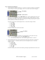
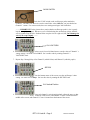
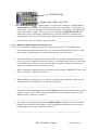
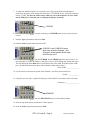
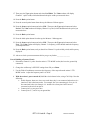
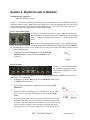
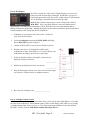
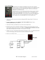
EET 1131 Lab #2 Name________________________________ Oscilloscope and Multisim Section 1. Oscilloscope Introduction Equipment and Components Safety glasses Logic probe ETS-7000 Digital-Analog Training System Fluke 45 Digital Multimeter Tektronix TDS2014 Digital Storage Oscilloscope Integrated Circuits: 7493 Part 1. Trainer’s TTL MODE Socket For many digital circuits, you’ll need to apply a periodic digital signal as the circuit’s input signal. As you learned in class, the red trainer has a function generator that can produce signals. When you use this function generator in other classes, you will often use the socket labeled OUTPUT. But in this course, you’ll always use the socket labeled TTL MODE instead of the OUTPUT socket. Let’s use the logic probe to examine the signal from the TTL MODE socket. 1. Using wires of the correct colors, connect your logic probe to the trainer’s +5 V and GND. 2. Set the function generator’s RANGE switch to x1, and set its FREQUENCY knob to 1. With these settings, what frequency have you set the function generator to produce? ____________ 3. Turn on the trainer’s power. Touch your logic probe’s tip to the trainer’s TTL MODE socket. What do you observe? ________________________________________________________________________ 4. Still touching the socket with your logic probe, slowly turn the function generator’s FREQUENCY knob clockwise until it’s set to 10. What do you observe as you turn the knob? ________________________________________________________________________ 5. With these settings, what frequency have you set the function generator to produce? ____________ 6. Set the function generator’s RANGE switch to x10, and set its FREQUENCY knob to 1. With these settings, what frequency have you set the function generator to produce? ____________ 7. Touching the socket with your logic probe, slowly turn the function generator’s FREQUENCY knob clockwise until it’s set to 10. What do you observe as you turn the knob? ________________________________________________________________________ 8. With these settings, what frequency have you set the function generator to produce? ____________ EET 1131 Lab #2 - Page 1 Revised 12/29/2014 Part 2. Setting Up the Oscilloscope 1. Turn the Tektronix TDS2014 oscilloscope on. After a few seconds of warming up, it will display a screen asking you to choose your language. Wait a few seconds for this screen to disappear. TRIG MENU Option buttons 2. Press the TRIG MENU button. On the right-hand side of the screen you should see the trigger menu, which lets you control five trigger settings called Type, Source, Slope, Mode, and Coupling. Notice that you can change these settings by pressing the five option buttons (which have no labels) next to the screen. For this lab, and for most work with digital circuits, we want these settings as follows: Type: Edge Source: CH1 Slope: Rising Mode: Auto Coupling: DC Check these settings, and correct them if needed. CH1 MENU 3. The Channel 1 trace should appear as a flat yellow line on the screen. If it is not displayed, press the yellow CH1 MENU button. Press this button multiple times. Notice that this toggles Channel 1 on and off. 4. On the right-hand side of the screen you should see the CH1 menu, which lets you control five settings for Channel 1. For this lab, and for most work with digital circuits, we want these settings as follows: Coupling: DC BW Limit: Off Volts/Div: Coarse Probe: 10X Invert: Off Check these settings, and correct them if needed by pressing the option buttons next to the screen. EET 1131 Lab #2 - Page 2 Revised 12/29/2014 1X/10X SWITCH 5. Check the 1X/10X switch on the oscilloscope probe attached to Channel 1, and make sure that it is set to the same Probe value (10X) that you just checked on Channel 1’s menu. For correct results, these two settings must agree with each other. ---------IMPORTANT: In the picture above, notice that the oscilloscope probe’s wire is gently looped, not tightly wrapped. Whenever you’re finished using the oscilloscope, please wind the wire in a gentle loop like this. Students often wrap the wire in a tight coil, but you’ll damage the wire if you wrap it tightly.------- CH1 VOLTS/DIV 6. In the screen’s lower left-hand corner, note the value of Channel 1’s voltage setting. We want it to be 5.00 V. Set it to this value by rotating Channel 1’s VOLTS/DIV knob. 7. Repeat Step 3 through Step 6 for Channel 2 (which is blue) and Channel 3 (which is purple). SEC/DIV 8. Near the bottom center of the screen, note the oscilloscope’s time setting. We want it to be 250 µs. Set it to this value by rotating the SEC/DIV knob. CH1 Vertical Position 9. Using each channel’s vertical position knob, adjust the traces so that Channel 1’s trace is located near the top of the screen, and Channel 2’s trace is located near the middle of the screen, and Channel 3’s trace is located near the bottom of the screen. EET 1131 Lab #2 - Page 3 Revised 12/29/2014 TRIGGER LEVEL Probe COMP ~5V @ 1kHZ 10. Connect Channel 1’s probe to the oscilloscope’s terminal labeled Probe COMP ~5V @ 1kHz. This will display a square wave on Channel 1. The display may not be stable. Note the small yellow arrow near the right edge of the display. This indicates the level of the Channel 1 trigger. Move it up or down by rotating the TRIGGER LEVEL knob. Notice that you get a stable display when this arrow is between Channel 1’s minimum and maximum limits, but you get an unstable display when you move the arrow outside these limits. 11. Ask me to check your setup before you go any further.________________ Part 3. Displaying Digital Signals on the Oscilloscope Let’s use the oscilloscope to display and measure the signal from the trainer’s TTL MODE output. 1. Set the function generator’s RANGE switch to x1k, and set its FREQUENCY knob to 1. With these settings, what frequency have you set the function generator to produce? ____________ 2. Disconnect Channel 1’s probe from the “Probe COMP ~5V @ 1kHz” terminal and use a short piece of red wire to connect the probe to the trainer’s TTL MODE socket. Also use a short black wire to connect the oscilloscope probe’s ground clip to the trainer’s Ground. You should see a square wave displayed on the oscilloscope’s screen. 3. While watching the oscilloscope screen, rotate the function generator’s FREQUENCY knob, and then set it back to 1. What do you observe? ________________________________________________________________________ 4. While watching the oscilloscope screen, turn the function generator’s RANGE switch to x10k, and then to x100, and then back to x1k. What do you observe? ________________________________________________________________________ 5. The trainer’s function generator also has a FUNCTION switch that lets you choose between sine, triangle, or square waves. While watching the oscilloscope screen, turn the switch to its three different settings. What do you observe? ________________________________________________________________________ 6. The trainer’s function generator also has an AMPLITUDE knob that lets you set the amplitude (height) of the waveform being produced. While watching the oscilloscope screen, rotate the knob through its entire range. What do you observe? ________________________________________________________________________ EET 1131 Lab #2 - Page 4 Revised 12/29/2014 7. To make sure that the frequency is accurately set to 1 kHz, use the Fluke 45 multimeter to measure the frequency of the output from the trainer’s TTL MODE socket. Adjust the frequency until it is 1 kHz. For the rest of this course, whenever you set the frequency to a new value, use the Fluke 45 to verify that you’re setting the frequency accurately. CURSOR 8. Press the oscilloscope’s CURSOR button to turn on the on-screen cursors. 9. Push the Type option button and select Time. 10. Push the Source option button and select CH1. CURSOR 1 and CURSOR 2 knobs, which also act as the Channel 1 and Channel 2 vertical position knobs when the LEDs are not lit. 11. Turn the CURSOR 1 and CURSOR 2 knobs to place Cursor 1 on the rising edge of a pulse on Channel 1, and place Cursor 2 on the falling edge of that same pulse. The time displayed under Delta in the Cursor Menu is the pulse width. Record this pulse width here. (Round all measurement values and calculation results to three digits.) Pulse width = _______________ 12. Use the cursors to measure the period of the Channel 1 waveform, and record it here. Period = _____________ 13. Using the previous value, compute the frequency of the Channel 1 waveform, and record it here. Frequency = ________________ MEASURE 14. Press the MEASURE button to see the Measure Menu. 15. Press the top option button; the Measure 1 Menu appears. 16. Press the Source option button and select CH1. EET 1131 Lab #2 - Page 5 Revised 12/29/2014 17. Then press the Type option button and select Pos Width. The Value readout will display Channel 1’s pulse width, which should match the pulse width you measured above. 18. Press the Back option button. 19. Press the second option button from the top; the Measure 2 Menu appears. 20. Press the Source option button and select CH1. Then press the Type option button and select Period. The Value readout will display Channel 1’s period, which should match the period you measured above. 21. Press the Back option button. 22. Press the third option button from the top; the Measure 3 Menu appears. 23. Press the Source option button and select CH1. Then press the Type option button and select Freq. The Value readout will display Channel 1’s frequency, which should match the frequency you computed above. 24. Press the Back option button, and you should see Channel 1’s pulse width, period, and frequency displayed. 25. Ask me to check your measurements before you go any further.________________ Part 4. Building a Counter Circuit 1. Disconnect Channel 1’s probe from the trainer’s TTL MODE socket (but leave the ground clip connected). 2. Change the oscilloscope’s SEC/DIV settings from 250 µs to 50 ms. 3. Use the Fluke 45 multimeter to measure the frequency of the output from the trainer’s TTL MODE socket. Adjust the frequency until it is 50 Hz. 4. With the trainer’s power turned off, build the circuit shown below, using a 7493 chip. Note the following: In this diagram, when two wires cross each other, they’re not connected unless there is a junction (a dot) at the intersection. For example, the wire connecting pin 12 to pin 1 is not connected to the wire from pin 14. And the wires from pins 8 and 9 are not connected to the wire from pin 10. Connect pin 5 to your power bus. Connect pins 2, 3, and 10 to your ground bus. EET 1131 Lab #2 - Page 6 Revised 12/29/2014 5. Turn the trainer’s power on. With the oscilloscope’s probes connected to the 7493’s pins as shown in the diagram above, you should see three waveforms on the oscilloscope’s display, but these waveforms will probably not be stable. 6. To stabilize the display, set the oscilloscope’s trigger to Channel 3 and adjust the trigger level. Whenever you display several signals of different frequencies, you should trigger on the lowest-frequency signal, which in this case is the signal on Channel 3. 7. Ask me to check your circuit before you go any further. Safety glasses? _________ Circuit works? ___________ DIP inserted correctly? ____________ Using power/ground busses?__________ Wire colors? _________ Wire lengths? ___________Wire ends trimmed? ___________ DIP accessible? ___________ 8. Press the oscilloscope’s CURSOR button to turn on the on-screen cursors, and then use the cursors to measure the pulse widths and periods of the waveforms on Channels 1, 2, and 3. From these values compute the frequencies. Record your values in the table below, rounded to three digits. Pulse width (Measured) Period (Measured) Frequency (Computed) Channel 1 Channel 2 Channel 3 9. Using the oscilloscope’s MEASURE button, display the frequencies of the waveforms on all three channels at the same time. 10. Ask me to check your measurements before you go any further.________________ 11. Without changing your circuit, increase the function generator’s frequency to 20 kHz and set the oscilloscope’s SEC/DIV setting to 100 s. Use the oscilloscope’s cursors to make the same EET 1131 Lab #2 - Page 7 Revised 12/29/2014 measurements that you made above, and record your data in the table below, rounded to three digits. Pulse width (Measured) Period (Measured) Frequency (Computed) Channel 1 Channel 2 Channel 3 12. Using the MEASURE button, display the pulse widths of all three channels at the same time. These pulse widths should be close to the values you recorded in your table. 13. Ask me to check your measurements.________________ 14. Don’t take the circuit apart yet—you’ll do one more thing with it in the next part of this lab. Part 5. Oscilloscope’s AUTO SET Button In Part 3 of this lab you learned which settings are usually the best settings for the parameters on the Trigger Menu and the Channel Menus. The Tektronix TDS2014 oscilloscope also has a very handy feature that automatically tries to pick the best settings for these parameters, based on the circuit currently connected to the oscilloscope. This AUTO SET feature does not always work perfectly, so it’s important for you to know how to check and adjust the various settings on your own. To see how AUTO SET works, follow these steps: 1. Mess up your current oscilloscope settings by randomly changing the settings on the Channel Menus and the Trigger Menu. Also, randomly turn the VOLTS/DIV knobs and the SEC/DIV knob. As you make these changes, the traces on the display will probably become difficult or impossible to read. 2. Press the AUTO SET button. You should find that, after a few seconds, the oscilloscope will fix the settings that you disturbed, resulting in a clearly readable display. 3. Examine the Channel Menus and the Trigger Menu. You should find that the oscilloscope has reset most of the parameters on these menus to their correct settings. 4. In your future work with this oscilloscope, use the AUTO SET button to make your job easier. But also remember that AUTO SET is not perfect. In many cases you’ll still have to adjust the settings to get the best display. 5. You’re finished with this circuit and can take it apart. ---------IMPORTANT: Remember that when you’re finished using the oscilloscope, you should wind the wire in a gentle loop. To avoid damaging the wire, do not wrap it in a tight coil.------- EET 1131 Lab #2 - Page 8 Revised 12/29/2014 REVIEW QUESTIONS 1. Based on your observations in Part 1, what conclusion can you draw regarding the usefulness of the logic probe for digital circuits whose logic levels are changing, rather than constant? Explain. 2. Based on your observations in Part 3, what can you conclude about the effect that the function generator’s four controls have on the signal produced at the TTL MODE socket? 3. What colors are the traces for the following channels? Channel 1 trace __________ Channel 2 trace __________ Channel 3 trace __________ 4. Suppose that Channel 1 is displaying a 1.5 kHz waveform, and Channel 2 is displaying a 900 Hz waveform, and Channel 3 is displaying a 2.0 kHz waveform. Which channel should your trigger source be set to? ________________ 5. In most cases, what are the best settings for the following parameters on the Channel menus? Coupling __________ BW Limit __________ Volts/Div __________ Probe __________ Invert __________ 6. In most cases, what are the best settings for the following parameters on the Trigger menu? Type __________ Slope __________ Mode __________ Coupling__________ Write down these standard channel settings and trigger settings in a handy place for future reference, and check these settings whenever you use the oscilloscope. Setting these parameters to other values can give confusing or incorrect results. FOR FURTHER STUDY: On the course website (in the Unit 2 folder) you’ll find a copy of this oscilloscope’s user manual. The manual is easy to read and contains some good hands-on exercises to teach you how to use the scope’s many features. I recommend that you save a copy of the manual on your flash drive and spend some time working through these exercises. EET 1131 Lab #2 - Page 9 Revised 12/29/2014 Section 2. Digital Circuits in Multisim Equipment and Components Multisim simulation software In EET 1116 (Electronics Schematics and Fabrication) you learned how to use the Multisim software to draw and simulate circuits. Multisim lets you simulate most of the lab equipment that you’ll use in this course, and most of the circuits that you’ll build in this course. The exercises below introduce you to some basic components and instruments used in digital circuits. Part 1: Power and Ground In Lab #1 you learned that the trainer’s power supply has both variable and fixed outputs. In digital circuits you’ll almost always use the trainer’s fixed +5 V supply by plugging wires into the +5 V socket and the GND socket. Multisim has several different power supplies, some variable and some fixed. It also has two grounds: an analog ground called GROUND and a digital ground called DGND. For simulating digital circuits, you’ll almost always use the power supply called VCC, which is fixed at 5 V, and the digital ground. 9. In Multisim, go into the Sources group and the POWER SOURCES family. Place a VCC and a DGND on your workspace. Part 2: Switches In Lab #1 you learned that the trainer has eight data switches that can be switched between HIGH (5 V) and LOW (0 V). To simulate these switches in Multisim, we’ll use single-pole-double-throw (SPDT) switches that are connected to VCC and DGND. 1. In Multisim, go into the Basic group and the SWITCH family. Place an SPDT on your workspace. 2. Flip the SPDT horizontally by right-clicking it and selecting Flip Horizontal. 3. Connect the switch’s terminals to VCC and DGND, as shown. Make the VCC wire red by right-clicking the wire and selecting Change Color…. 4. Notice that pressing the space bar on your keyboard causes the switch to flip back and forth. You can also flip the switch by clicking it with the mouse. But you’ll find that when you have a lot of switches in your circuit, using the keyboard is easier and faster than using the mouse. I’ll always expect you to assign a different key to each switch, so that EET 1131 Lab #2 - Page 10 Revised 12/29/2014 each switch can be controlled individually by its own key. To do this, double-click your switch, select the Value tab, and choose 0 in the drop-down box. Then click OK. Notice that now you can control the switch using the 0 key on your keyboard, instead of the space bar. Part 3: Digital Probes In Lab #1 you learned that the trainer has eight LEDs. Each LED lights up if its socket is connected to a high point in a circuit, but it stays dark if connected to a low point (or to a point that is floating). Multisim has several ways to simulate an LED. The easiest and fastest way is to use a digital probe (PROBE_DIG). These probes come in several colors, including white. I recommend using colored ones instead of white ones, because the colored ones make it much easier to see whether the LED is lit or dark. 1. In Multisim, go into the Indicators group and the PROBE family. Place a PROBE_DIG_RED on your workspace. 2. Change the probe’s label to LED0 (by double-clicking the probe and selecting the Label tab). 3. Connect the probe to the switch as shown. 4. Simulate your circuit (by pressing the green Run arrow). Notice that as you flip the switch high or low, the probe lights or goes dark. For many circuits you’ll need several switches for inputs, so let’s see how to build a bank of four switches connected to four probes. 5. In Multisim, disconnect your switch from VCC and DGND. 6. Copy and paste your switch and probe three times. 7. Change the labels on the new probes, and the key assignments on the new switches, to match those shown. Also connect the switches to VCC and DGND as shown. 8. Simulate your circuit. Notice that you can use the keys on your keyboard for individual control of each switch. 9. Show me your working circuit. ___________________ EET 1131 Lab #2 - Page 11 Revised 12/29/2014 Part 4: Hex Displays In Lab #1 you used one of the trainer’s Digital Displays to convert four binary bits to the decimal digits 0 through 9. Recall that if you gave it a binary input greater than 9 (in other words, a binary input of 10102 through 11112), the display want blank instead of showing a digit. Multisim has a similar component (in several exciting colors) named DCD_HEX. There’s one main difference between it and the trainer’s digital display: for binary inputs greater than 9, DCD_HEX shows the correct hexadecimal digit (A through F) instead of going blank. Although the displays on our trainer go blank for inputs greater than 9, some real displays work exactly like the one in Multisim. 1. In Multisim, copy and paste your entire circuit. On this new copy, delete the four probes. 2. Go into the Indicators group and the HEX_DISPLAY family. Place a DCD_HEX on your workspace. 3. Connect the DCD_HEX to your four new switches as shown. 4. Simulate your circuit. Go through all possible switch combinations in order, from 00002 to 11112. Notice that for each combination, the display shows the correct hex digit. 5. Of the six alphabetic digits (A through F), which ones are displayed as upper-case letters? _____________ 6. Which ones are displayed as lower-case letters? _____________ 7. Why did the designers choose to use lower-case instead of uppercase for these? Explain clearly in complete sentences. 8. Show me your working circuit. ___________________ Part 5: A Simple Counter Circuit In Lab #1 you built a circuit using a 7490 counter chip, a pulse switch, and a digital display. Let’s build the same circuit in Multisim. (Recall that the trainer’s pulse switch changes value while you’re pressing it, and then change back when you release it. The closest component in Multisim is the switch called PB_DPST, which is short for Push-Button, Double Pole-Single Throw.) EET 1131 Lab #2 - Page 12 Revised 12/29/2014 1. In Multisim, go into the TTL group and the 74STD family. Place a 7490N on your workspace. 2. Connect the 7490N to a PB_DPST and a DCD_HEX as shown below. 3. Simulate your circuit. Each time you operate the PB_DPST, the displayed digit should increase by one. 4. Show me your working circuit. ___________________ Part 6: Measurement Probe In Lab #1 you used a logic probe to test points in a circuit. The probe tells you whether that point is at a HIGH or LOW level. Multisim has a Measurement Probe that is similar to a logic probe, but more versatile. It can also be used in analog circuits to tell you the exact voltage at a point in the circuit. 1. In Multisim, simulate the counter circuit that you built above. 2. In the Instruments toolbar on the screen’s right edge, locate the Measurement Probe, which looks like this: 3. Click the Measurement Probe, and then move your mouse to the left. You’ll see a box like this. Of the five lines in this box, for this course we will only be interested in the first line (V: for voltage) and the last line (Freq: for frequency). 4. Move the probe over various wires in your simulating circuit, and note that it changes to tell you the voltage at that point. With digital circuits, you may see an actual voltage value (usually 0 V or 5.00 V), or you may see the words “HIGH” and “LOW.” EET 1131 Lab #2 - Page 13 Revised 12/29/2014 Part 7: Clock Voltage You learned in Lab #2 that the TTL MODE socket on the trainer’s function generator produces a periodic digital signal that changes between HIGH and LOW. You also learned that you can control the signal’s frequency by adjusting the FREQUENCY and RANGE knobs. In Multisim, there are several components that behave like the trainer’s function generator. The one that behaves most like the trainer’s TTL MODE socket is called CLOCK_VOLTAGE. We’ll use this one very often in this digital course. In other courses you’ll use other components that, like the trainer’s OUTPUT socket, produce sine waves and triangle waves as well as square waves. 1. In Multisim, modify your previous circuit by deleting the SPDT, along with the VCC that it was connected to. 2. Go into the Sources group and the SIGNAL_VOLTAGE_SOURCES family. Place a CLOCK_VOLTAGE on your workspace. 3. Connect the CLOCK_VOLTAGE to the rest of the circuit as shown below. 4. Double-click the CLOCK_VOLTAGE, and change its frequency from 1 kHz to 20 Hz. In a real circuit, 20 Hz would be too fast for our eyes to follow. But simulated time in Multisim runs much slower than real time in the real world, so 20 Hz should be about right. 5. Simulate your circuit. The displayed digit should cycle through its values. Use a Measurement Probe to observe the changing values on the wires between the 7490 and the DCD_HEX. 6. Show me your working circuit. ___________________ EET 1131 Lab #2 - Page 14 Revised 12/29/2014 Part 8: Oscilloscope In Lab #2 you learned that the oscilloscope lets you “see” digital signals that are changing too fast for your eye to follow using a logic probe. The oscilloscope is a complex and powerful instrument that any technician must know how to use. Multisim has several oscilloscopes. Two of these (called Oscilloscope and 4-Channel Oscilloscope) are generic simulations whose front panels have controls similar to the ones found on real oscilloscopes—but they’re not meant to look exactly like any real scope. Another one (called Tektronix Oscilloscope) is designed to look and behave like the Tektronix 2024 scopes that we have in our EET labs. This is a great learning tool, because it lets you practice using a realistic oscilloscope at home or anywhere you have access to a computer running Multisim. 1. In Multisim, modify your previous circuit by deleting the DCD_HEX. 2. Change the CLOCK_VOLTAGE’s frequency to 10 kHz. 3. In the Instruments toolbar on the screen’s right edge, locate the Tektronix Oscilloscope, which should be just above the Measurement Probe. 4. Place the Tektronix Oscilloscope, and connect it to the rest of the circuit as shown. 5. Simulate your circuit. Double-click the Tektronix Oscilloscope, and you should see a front panel that looks very much like the real oscilloscope. Using its Power button, Vertical Position knobs, VOLTS/DIV knobs, and SEC/DIV knob, adjust the oscilloscope’s settings until the display look something like this. Also use the MEASURE button to display the frequencies on all four channels. 6. Show me your working circuit. _____________ EET 1131 Lab #2 - Page 15 Revised 12/29/2014 Part 9: Logic Analyzer A logic analyzer is similar to an oscilloscope. Here’s one advantage to using a logic analyzer: logic analyzers usually let you display eight or sixteen or more signals at a time, while most oscilloscopes only let you display two or four signals. But here’s a disadvantage: logic analyzers can only display digital signals, unlike oscilloscopes, which can display sine waves, triangle waves, and other waveforms important in analog electronics. So you can think of a logic analyzer as a specialized oscilloscope that lets you display many digital (but not analog) signals at a time. Sinclair’s EET department owns a few logic analyzers. But for most technicians, knowing how to use an oscilloscope is more important, and often an oscilloscope will let you make all the measurements you need to make in digital circuits. So in this course we’ll focus on the oscilloscope. Some of our textbook’s Multisim examples use the logic analyzer, so let’s learn a little about it. 1. In Multisim, modify your previous circuit by deleting the Tektronix Oscilloscope. 2. In the Instruments toolbar, locate the Logic Analyzer (about halfway down the list). 3. Place the Logic Analyzer, and connect it as shown below. 4. Simulate your circuit. Double-click the Logic Analyzer, and you should see a graph of the four signals, similar to what you would see on an oscilloscope. 5. Stop the simulation. Note that right below the signal display area is a scrollbar that lets you scroll back in time to the beginning of the simulation. 6. Show me your working circuit. ___________________ Part 10: Word Generator Multisim’s Word Generator is not like any real-world instrument that you’ll find in Sinclair’s EET labs. It gives you an easy way to generate any pattern of bits that you might like to use to test a digital circuit in Multisim. Some of our textbook’s Multisim examples use the word generator. To learn a little about how to use it, work through the Multisim examples in Chapter 2 of the textbook. EET 1131 Lab #2 - Page 16 Revised 12/29/2014