1
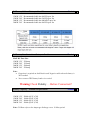
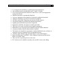
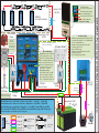
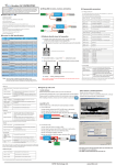
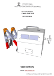
Print Form
SuperCombi & CombiPlus
Quick Install & Programming Check List for
Recreational Power Systems
This check list provide basic programming and commissioning information for your
Combi Series Inverter in a Caravan, RV & Marine Applications.
Please make sure you have read and understood the User Manual before attempting to
power up you Combi inverter. If you are unsure please contact [email protected]
This checklist should be used in conjunction with AS 3000 Wiring Rules
Recreations Power System design must comply with you local mandatory requirements,
and should follow the recommendations of AS4509.2 SPS Design Guidelines.
DC Battery Cable – “Battery to Combi”
1500W
1500W
3000W
3000W
12V
24V
12V
24V
Checked
Recommended cable size 0AWG up to 2m
Recommended cable size 2AWG up to 2m
Recommended cable size 000AWG up to 2m
Recommended cable size 0AWG up to 2m
DC Battery Fuse Protection – Battery to Combi
Checked
MAX DC Fuse Size:
1500W 12V 250Amp
1500W 24V 125Amp
3000W 12V 500Amp
3000W 24V 250Amp
Note:
• Protection is required on both Positive and Negative cables when the battery is
NOT earthed.
• Never connect TWO battery banks via a switch.
Warning Check Polarity…. Before Connection!!
Battery Capacity – Minium Requirements
1500W
1500W
3000W
3000W
12V
24V
12V
24V
200Ah @12V (C10)
100Ah @24V (C10)
400Ah @12V (C10)
200Ah @24V (C10)
Note: C10 Rate refers to the Amperage discharge over a 10 Hour period.
Checked
AC Wiring Connections to Combi
Checked
The AC Input Current limit from the AC Generator or Mains Grid supply must be set in
the Combi’s AC Input Current setting B2-05.
The length of the AC input cable is also required to calculate the correct size that should
be used when allowing for maximum input and outputs:
Note: Never connect the AC supply without the battery connected.
If you are not using the boosting feature from the AC input, you can prevent the Combi
from going into over load by using a smaller AC Breaker on the output side of the
inverter.
Example: 1500W use 6 Amp, for the 3000W use 10 Amp standard “C-Type” breaker.
Breaker Size recommendations if not using the Boosting feature or AC Generator
Model
MCB / RCD
Curve Type
1500watt
6 Amps
C-Type (Standard)
3000watt
10 Amps
C-Type (Standard)
6000watt
20 Amps
C-Type (Standard)
B2-01~08: AC Input Voltage & Frequency Input Check Table
Checked
The following Check Table is a summary of the following sections.
Setting
Function
B2-08=0
B2-08=1
B2-01=190
B2-02=197
B2-03=255
B2-04=260
B2-05= AMPS
B2-06=1
(Active)
B2-07=1
B2-09=1
B2-09=0
When B1-01=0: Acceptable AC input frequency is 50Hz ±5Hz
(45~55Hz)
When B1-01=1: Acceptable AC input frequency is 60Hz ±5Hz
(55~65Hz)
Accept wide AC input frequency range between 45~65Hz
AC Low input Cut out Voltage (190VAC)
AC Low input Cut in Voltage (197VAC)
AC High input Cut in Voltage (255VAC)
AC High input Cut out Voltage (260VAC)
AC Input Current (3.33x VA of AC Generator = AMPS)
When using a Generator then you must always use wave
form check “Active”
The internal ground relay is closed “Internally the Neutral &
GND are joined when in inverter mode only.(AC Out)”
MODE 2: B2-09=1
Dynamic Power: Dynamic. Used this feature when operating
smaller AC Generator less than 3kVA. AC load is supported by
the Inverter then slowly pushed across to the Generator.
MODE 1: B2-09=0
Dynamic Power: Normal. Select Normal when operating larger
AC Generators or when connected to Mains Grid. The AC load
is supported directly by the AC Generator or Mains Grid.
B2-08: AC Input Frequency
•
•
Checked
Check the AC Input and Frequency ranges are set correctly.
The default setting is for wide range of voltage and frequency.
If your system is using a cheaper style generator we recommend you adjust the
Combi for a more selective range,
Example: B2-08= 0 (45~55Hz) Narrow range,
B2-08=1 (45~65Hz) Wide range.
B2-01~04: AC Input Voltage
•
If your system is using a cheaper style AC Generator we recommend you adjust
the Combi for a narrower voltage range to offer better protection to your
appliances and the Combi. These Voltage input parameters can be adjusted:
Example: LOW:
HIGH:
B2-01=190VAC and B2-02=197VAC,
B2-03=255VAC and B2-04=260VAC
B2-05: AC Input Current
•
Checked
Checked
It is very important to correctly program your Combi to suit the size of your AC
Generator or Mains Supply!!
If you don’t, Power Share, Power Support, Dynamic Power Shifting will NOT
work! Furthermore, you can overload your inverter!
•
MODE 1: Never set the Combi’s AC input “B2-05” & B2-18 higher than
16AMPS, we recommend 13~15Amps to avoid tripping of the Shore power
breaker. Remember that you MUST be operating in MODE 1 when you are
programming these steps.
•
MODE 2: YOU MUST Never set the Combi’s AC input “B2-05” & B2-19
higher than the Continuous output rating of your AC Generator or mains supply.
Remember that you MUST be operating in MODE 2 when you are programming
these steps.
•
Generally, a good rule of thumb is take the AC Generators kVA rated output and
multiply it by 3.33, Example: If you have a 3.6kVA AC Generator, then the
maximum AC Input Current is 3.6 x 3.33. = 12 Amps (11.99).
•
We recommend you use this rule to set the AC Input Current to the Combi.
This is programmed into B2-05 settings; also check B2-18~21 these should be the
same value as set in B2-05. We recommend the use of inverter style AC
Generators.
•
USE ONLY Mode 2 for AC Generators. and MODE 1 AC Input setting should be
13~15Amps Max 16Amps.
•
For more on Mains AC connected systems please refer to the User Manual.
B2-06: AC Input Current
•
B2-06=1 (Active) When using a Generator then you must always use wave form
check “Active”
B2-07: AC Ground Relay (MEN)
•
Checked
B2-07=1 (Closed). For use in Marine and Caravan installations were there is NO
MEN point on the AC output then the Ground Relay must be activated. See
AS3000 for more info.
Battery Charger Settings
•
•
Checked
Checked
Check that the correct charger voltages have been adjusted to suit your battery.
Failure to do so can destroy your batteries and could damage the Combi.
Example: PowerStacks SB-1800 & SB-1802 & PowerSleak SB-1822 “AGM” –
24V System
D1-03=26.76 Absorb / Bulk 27.6V
D1-07=23.76 Float 26.76V
D1-10= 0
Equalization charge OFF,
12V System
D1-03=13.80 Absorb / Bulk 13.8V
D1-07=13.50 Float 13.5V
D1-10= 0
Equalization charge OFF,
D1-08 Please DO NOT ADJUST the battery charger current D1-08
Unless you have consulted with us first.
General Installation Checklist
•
•
•
•
•
•
•
•
•
•
•
•
•
•
•
•
•
•
Checked
LV wiring must be installed by a qualified electrical tradesperson
Safe isolation must be provided between ELV and LV Circuits
Over-current protection and isolation are rated for AC or DC at the appropriate
voltage and currents.
Shutdown procedure is prominently displayed
Access to equipment such as batteries is restricted to authorised personnel
Adequate ventilation is provided to all electrical equipment
All cables satisfy both voltage drop and current carrying capacity
All exposed cabling is provided with mechanical protection
Lighting protection has been provided (if required).
Equipment is labelled, convenient, accessible and visible
There are no live parts accessible on any installed equipment.
Main Battery over-current protection installed in all un-earthed conductors
A means to readily isolate the battery bank is installed
The batteries are installed in a appropriate ventilated dedicated room, enclosure or
restricted access area designed to prevent unauthorised entry
“Warning- Spark Hazard” sign is mounted above or next to the batteries
Battery warning signs “DANGER – Risk of Battery Explosion and Electrolyte
Burns” are clearly visible.
There are NO arc producing devices in the area.
ELV cables are to be labelled to identify solar, and DC circuits, and cabling.
Roof Area
DIP Switch Settings:
No.3 ON (Up), 1,2,4,5,6,7,8 OFF
BDC Network Switch Settings:
No.1 (CombiNet Address 1)
SunStar SS-45C
MP-3726
From SuperCombi PORT- C (EXT)
SuperCombi Settings
Important: Make Sure B2-05 AC Input
Has been programmed correctly
B2-05 & 18= 15 (AC input 15Amps)
Mode 1 operating for Mains power
Mode 2 operation for AC Generator
B2-05 & 19=? (3.33x KVA Generator)
Note: Mode 2 AC Generators Over
3KVA set B2-09 = 0 “Normal”
Battery Charger Settings:
D1-03 “Absorb Volatge = 13.8VDC”
D1-07 “Float Voltage = 13.5VDC”
D1-08 “Charger Current = 35Amp”
D1-10 = 0 “Equalization Charge Off”
AC Input
250Amp
BTS - Battery Temperature Sensor wire
125Amp
FUSE
Battery Bank 12VDC
SB-1822
BTS
FUSE
Max Cable distance from Solar Panels to SunStar Solar Controller - 3m @ 4mm2 , 4.5m @ 6mm2
Max Cable distance from SunStar Solar Controller to Battery Bank - 6m @ 8AWG , 16m @ 4AWG
Max Cable distance from SuperCombi to Battery Bank - 1m @ 4AWG , 1.5m @ 2AWG, 2.5m @ 0AWG
Cable size for DC-SW: 8AWG Max 22Amp, 4AWG Max 60Amp, 2AWG Max 90Amp, 0AWG 140Amp @ 6m
Small Ground
cable from DC-SW
FUSE
RCD/MCB
16Amp
40Amp
FUSE
Inverter AC Output
MP-3726
DC-SW-140
CombiNet - IN
RCD/MCB
20Amp
AC load
MODE 1: Set B2-05 & 18=15
AC Input Current 15Amps
CombiNet - OUT
AC Output 240VAC
From SuperCombi PORT C (EXT)
To DC-SW (MI-5258)
SunStar SS-60C Settings
DC-SW-140 Settings
Main Menu>Programming>ENT>Communication>ENT
Communication settings: P1-01= 2 (CombiNet Mode)
P1-04=1 (CombiNet Address 1)
Main Menu>Programming>ENT>General>ENT>
DC-SW Operation Sel> ENT
B1-01=0 (DC/DC Charger)
Main Menu>Programming>ENT>General>ENT>
Set Battery Voltage> ENT
B1-02=12 (Battery Voltage 12VDC)
CombiNet - IN
Note: This is a RJ50 (MOD10) connection
with 10 core cable. WI-5252
AC Inlet
OUT
30Amp
SuperCombi 1500W
MI-5250
MODE 2:
Set B2-05 & 18
AC Input Current
= 3.33x KVA rating
See check list for
more information.
Shore / Park
AC Power
IN
125Amp
Note: Max Cable distance is calculated at less than 5% voltage drop.
80W
Solar Panel
KEY
FUSE
40Amp DC
FUSE
125Amp DC
FUSE
30Amp DC
FUSE
250Amp DC
Battery Fuse
Solar Connector
PS-5102
Solar Connector
PS-5100
Solar Y-Lead
PS-5112
Solar Y-Lead
PS-5112
Alternator
Start Battery
EXAMPLE: Power System-320 Watt Solar Schematic
AC Generator
Power
FUSE
EXAMPLE:
4x 80 Watt Solar Panels