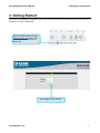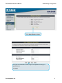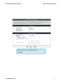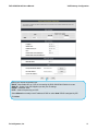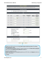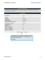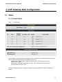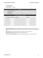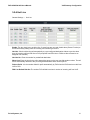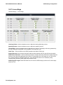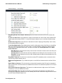
1
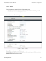
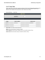
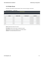
DVG-3032S/3016S VoIP Gateway User’s Manual Version 1.0 (May 2011) © 2011 D-Link Corporation. All rights reserved. Reproduction in any manner whatsoever without the written permission of D-Link Corporation is strictly forbidden. Trademarks used in this text: D-Link and the D-Link logo are trademarks of D-Link Corporation/D-Link Systems Inc.; Other trademarks and trade names may be used in this document to refer to either the entities claiming the marks and names or their products. D-Link Corporation disclaims any proprietary interest in trademarks and trade names other than its own. Warranty: please contact your D-Link Authorized Reseller or the D-Link Branch Office nearest your place of purchase for information about the warranty offered on your D-Link product. Information in this document is subject to change without notice. FCC Warning This equipment has been tested and found to comply with the limits for a Class B digital device, pursuant to Part 15 of the FCC Rules. These limits are designed to provide reasonable protection against harmful interference in a residential installation. This equipment generates, uses, and can radiate radio frequency energy and, if not installed and used in accordance with the instructions, may cause harmful interference to radio communication. However, there is no guarantee that interference will not occur in a particular installation. If this equipment does cause harmful interference to radio or television reception, which can be determined by turning the equipment off and on, the user is encouraged to try to correct the interference by one or more of the following measures: ‧ Reorient or relocate the receiving antenna. ‧ Increase the separation between the equipment and receiver. ‧ Connect the equipment into an outlet on a circuit different from that to which the receiver is connected. ‧ Consult the dealer or an experienced radio/TV technician for help. CE Mark Warning This is a Class B product. In a domestic environment, this product may cause radio interference in which case the user may be required to take adequate measures. Warnung! Dies ist ein Produkt der Klasse B. Im Wohnbereich kann dieses Produkt Funkstoerungen verursachen. In diesem Fall kann vom Benutzer verlangt werden, angemessene Massnahmen zu ergreifen. Precaución! Este es un producto de Clase B. En un entorno doméstico, puede causar interferencias de radio, en cuyo case, puede requerirse al usuario para que adopte las medidas adecuadas. Attention! Ceci est un produit de classe B. Dans un environnement domestique, ce produit pourrait causer des interférences radio, auquel cas l`utilisateur devrait prendre les mesures adéquates. Attenzione! Il presente prodotto appartiene alla classe B. Se utilizzato in ambiente domestico il prodotto può causare interferenze radio, nel cui caso è possibile che l`utente debba assumere provvedimenti adeguati. Contents 1. Introduction ........................................................................................................................................................ 4 1-1 Product Overview ....................................................................................................................................... 4 1-2 Hardware Description ................................................................................................................................. 5 2. Getting Started ................................................................................................................................................... 7 3. VoIP Gateway Web Configuration .................................................................................................................. 13 3-1 Status ........................................................................................................................................................ 13 3-1-1 Current Status ................................................................................................................................ 13 3-1-2 RTP Packet Summary .................................................................................................................... 14 3-1-3 System Information ........................................................................................................................ 15 3-1-4 Routing Table ................................................................................................................................. 16 3-1-5 LAN Client ...................................................................................................................................... 16 3-2 General Settings ....................................................................................................................................... 17 3-2-1 WAN ............................................................................................................................................... 17 3-2-2 LAN ................................................................................................................................................ 21 3-2-3 SIP.................................................................................................................................................. 22 3-2-4 SIP Advanced ................................................................................................................................. 26 3-2-5 Caller ID ......................................................................................................................................... 30 3-2-6 Hot Line .......................................................................................................................................... 31 3-2-7 Line settings ................................................................................................................................... 32 3-2-8 FAX................................................................................................................................................. 35 3-2-9 Calling Features ............................................................................................................................. 37 3-2-10 Phone Book .................................................................................................................................. 38 3-2-11 CDR Settings ................................................................................................................................ 39 Advanced Settings .......................................................................................................................................... 40 Advanced Settings .......................................................................................................................................... 40 3-2-12 Codec setting ............................................................................................................................... 40 3-2-13 Digit Map ...................................................................................................................................... 41 3-2-14 DTMF & PULSE ........................................................................................................................... 44 3-2-15 CPT / Cadence ............................................................................................................................. 45 3-2-16 TR069........................................................................................................................................... 46 3-2-17 Caller Filter ................................................................................................................................... 48 3-2-18 Static Route .................................................................................................................................. 49 3-2-19 QoS Settigs .................................................................................................................................. 50 3-2-20 DDNS ........................................................................................................................................... 51 3-2-21 NAT Traversal............................................................................................................................... 52 3-2-22 DoS Protection ............................................................................................................................. 53 3-3 SNMP ....................................................................................................................................................... 54 3-4 Tools ......................................................................................................................................................... 55 3-4-1 Ping Test......................................................................................................................................... 55 3-4-2 STUN Inquiry .................................................................................................................................. 56 3-5 System Settings ........................................................................................................................................ 57 3-5-1 NTP ................................................................................................................................................ 57 3-5-2 Login Account ................................................................................................................................. 58 3-5-3 Backup / Restore ............................................................................................................................ 59 3-5-4 System Log .................................................................................................................................... 60 3-5-5 Save / Restart................................................................................................................................. 60 3-5-6 Software Upgrade .......................................................................................................................... 61 3-5-7 Logout ............................................................................................................................................ 61 4. Configuring the VoIP Gateway through IVR .................................................................................................. 62 4-1 IVR (Interactive Voice Response) ............................................................................................................ 62 4-2 IP Configuration Settings—Set the IP Configuration of the WAN Port..................................................... 64 5. Dialing Principles ............................................................................................................................................. 66 5-1 Dialing Options ......................................................................................................................................... 66 5-2 Dialed Number Processing Flow .............................................................................................................. 66 Appendix ............................................................................................................................................................... 68 Product Features ............................................................................................................................................ 68 DVG-3032S/3016S User’s Manual Product Overview 1. Introduction 1-1 Product Overview The DVG-3032S/3016S are designed to carry both voice and facsimile over the IP network. It uses the industry standard SIP call control protocol so as to be compatible with free registration services or VoIP service providers’ systems. As a standard user agent, it is compatible with all common Soft Switches and SIP proxy servers. While running optional server software, the VoIP Gateway can be configured to establish a private VoIP network over the Internet without a third-party SIP Proxy Server. The DVG-3032S/3016S can be seamlessly integrated into an existing network by connecting to a phone set and fax machine. With only a broadband connection such as an ADSL bridge/router, a Cable Modem or a leased-line router, the VoIP Gateway allows you to use voice and fax services over IP in order to reduce the cost of all long distance calls. The DVG-3032S/3016S can be configured a fixed IP address or it can have one dynamically assigned by DHCP or PPPoE. It adopts either the G.711, G.726, G.729A or G.723.1 voice compression format to save network bandwidth while providing real-time, toll quality voice transmission and reception. D-Link Systems, Inc. 4 DVG-3032S/3016S User’s Manual Telephone Interface Description 1-2 Hardware Description Front Pannel DVG-3016S DVG-3032S Indicators Power: Power LED. A steady light indicates a proper connection to a power source. VoIP: The VoIP LED will turn on when the VoIP Gateway is connected to a VoIP service provider. The LED will blinking if not connected to a service provider. Alarm: A blinking light indicates the VoIP Gateway is attempting to connect with the Provisioning server or DVG can’t get IP from DHCP or PPPoE Server. Once the service connects, the LED will turn off. The LED will light solid red if the self-test or boot-up fails. Run: The heartbeat, a blinking light indicates the VoIP Gateway keep running. WAN: When a connection is established the 10 or 100 LED will light up solid. The LED will blink to indicate activity. If the 10 or 100 LED does not light up when a cable is connected, verify the cable connections and make sure your devices are powered on. LAN: When a connection is established the 10 or 100 LED (bottom) will light up solid on the appropriate port. The LEDs will blink to indicate activity. If the 10 or 100 LED does not light up when a cable is connected, verify the cable connections and make sure your devices are powered on. Phone: Green Blinking – FXO is detecting incoming alerting. Green Solid – The line is in use. Connectors WAN: Connect to your broadband modem using an Ethernet cable. LAN: Connect to your Ethernet enabled computers using Ethernet cabling. Reset: Press and hold the reset button for 5 seconds., release button as Alarm is blinking. That DVG will restore to factory default. To restore factory default settings: 1. Press and hold the reset button for 6 seconds. 2. Release the reset button. Factory settings will be restored. D-Link Systems, Inc. 5 DVG-3032S/3016S User’s Manual Telephone Interface Description Rear Panel DVG-3016S DVG-3032S FXO Connector: Connect to your phones using attached phone cabling. Ground: A conducting connection with the earth. Connect with the ground so as to make the earth a part of an electrical circuit using metal wire. Power Receptor: Receptor for AC power 100V- 240V. D-Link Systems, Inc. 6 DVG-3032S/3016S User’s Manual VoIP Gateway Configuration 2. Getting Started To access the web-based configuration utility, open a web browser such as Internet Explorer and enter the IP address of the DVG-3032S/3016S. Open your Web browser and type http://192.168.8.254 into the URL address box. Press the Enter or Return Key. Click Login to enter Web Site. D-Link Systems, Inc. 7 DVG-3032S/3016S User’s Manual VoIP Gateway Configuration Click Setup Wizard and Next. It is highly recommended to create a login ID and password to keep your gateway secure. Click Next. D-Link Systems, Inc. 8 DVG-3032S/3016S User’s Manual VoIP Gateway Configuration Enter a NTP server or use the default server. Click Next. D-Link Systems, Inc. 9 DVG-3032S/3016S User’s Manual VoIP Gateway Configuration Select your Internet connection type: DHCP – Most Cable ISPs or if you are connecting the DVG-3032S/3016S behind a router. Static IP – Select if your ISP supplied you with your IP settings. PPPoE – Most DSL ISPs. PPTP – Select if required by your ISP. Select Manual to manually enter IP address of DNS or select Auto if DNS is assigned by ISP. Click Next. D-Link Systems, Inc. 10 DVG-3032S/3016S User’s Manual VoIP Gateway Configuration Register to the SIP Proxy Server by clicking Enable support of SIP Proxy Server. Enter Proxy Server IP/Domain and Port. The Outbound Proxy Support is optional. To register, please click on the Outbound Proxy Support check box and enter Outbound Proxy IP/Domain and Port in it. Registration by phone line: enter Number, User ID/Account and Password supplied by your ITSP. Click on the Register check box to register to Proxy Server. Click Next. D-Link Systems, Inc. 11 DVG-3032S/3016S User’s Manual VoIP Gateway Configuration Setup is finished. Check the summary of your settings. To make new settings effective, you must click on the Restart button to reboot the DVG-3032S/3016S. Click Restart. D-Link Systems, Inc. 12 DVG-3032S/3016S User’s Manual VoIP Gateway Configuration 3. VoIP Gateway Web Configuration 3-1 Status 3-1-1 Current Status Status → Current Status For Port Status, it includes if each port registers to Proxy successfully, the last dialed number, how many calls each port has made since the VoIP Gateway is start, etc. Number-voip: It displays calling number for direction VoIP-> FXO or called number for direction FXO-> VoIP. Number-pstn: It displays called number for VoIP-> FXO one-step directly call or calling number for direction FXO-> VoIP For Server Registration Status, it shows the registration status of DDNS, STUN and FXS Represent Number. D-Link Systems, Inc. 13 DVG-3032S/3016S User’s Manual VoIP Gateway Configuration 3-1-2 RTP Packet Summary Status → RTP Packet Summary Display the information of the last call made. Press Refresh button to get the latest RTP Packet Summary. D-Link Systems, Inc. 14 DVG-3032S/3016S User’s Manual VoIP Gateway Configuration 3-1-3 System Information Status → System Information For WAN Port Information, it shows IP address, subnet mask, default gateway and DNS server. If you use PPPoE to obtain IP, you will know if the IP is obtained through this method. If IP address, subnet mask, default gateway is blank, it means that the VoIP Gateway does not obtain IP. For LAN Port Information, it shows LAN port IP, subnet mask, and the status of DHCP server. For Hardware, it shows the hardware platform and driver version. D-Link Systems, Inc. 15 DVG-3032S/3016S User’s Manual VoIP Gateway Configuration 3-1-4 Routing Table Status → Routing Table It displays routing table of DVG-3032S/DVG-3016S. 3-1-5 LAN Client The DHCP Clients table displayed LAN device that has already been assigned an address from DVG-3032S/3016S. You can check if the DHCP client has obtain an IP address. Status → LAN Client D-Link Systems, Inc. 16 DVG-3032S/3016S User’s Manual VoIP Gateway Configuration 3-2 General Settings 3-2-1 WAN WAN (Wide Area Network) Settings are used to connect to your ISP (Internet Service Provider). The WAN settings are provided to you by your ISP and oftentimes referred to as "public settings". Please select the appropriate option for your specific ISP. IP Configuration (Setting WAN Port) There are five methods of obtaining a WAN port IP address: 1. DHCP, which means a Dynamic IP (Cable Modem) 2. Static IP 3. PPPoE (dial-up ADSL) 4. PPTP Methods for using DHCP and PPPoE for obtaining an IP address may vary. If you are not familiar with creating a network connection, please contact your local ISP. After selecting the suitable option, click Accept at the bottom of the screen to save the settings. You need to save the changes and restart the VoIP Gateway to make the changes active. Saving the settings: Click Save/ Restart in System from the left menu. Tick Save Settings and Restart then click Accept. Wait for about 50 seconds before the VoIP Gateway obtaining an IP address by the method you selected. Note: When the system has obtained a new IP address, and you are using a WAN port to enter the Web Configuration Screen, the new IP address has to be used before you can get connected to the VoIP Gateway. The same principle applies to the next two settings. General Settings → WAN D-Link Systems, Inc. 17 DVG-3032S/3016S User’s Manual VoIP Gateway Configuration General Settings → WAN DHCP: Select this option if your ISP (Internet Service Provider) provides you an IP address automatically. Cable modem providers typically use dynamic assignment of IP Address. The Host Name field is optional but may be required by some Internet Service Providers. General Settings → WAN Static IP: Select this option if your ISP (Internet Service Provider) provides you a Static IP address. Enter the IP address, Subnet Mask and Default Gateway IP. D-Link Systems, Inc. 18 DVG-3032S/3016S User’s Manual VoIP Gateway Configuration General Settings → WAN PPPoE: Select this option if your ISP requires you to use a PPPoE (Point-to-Point Protocol over Ethernet) connection. Enter the PPPoE Account, PPPoE Password and re-enter Password to confirm. General Settings → WAN PPTP: Point-to-Point Tunneling Protocol (PPTP) is a WAN connection. Enter the IP Address, Subnet mask, PPTP Server, PPTP ID and Password. D-Link Systems, Inc. 19 DVG-3032S/3016S User’s Manual VoIP Gateway Configuration General Settings → WAN Factory Default MAC Address: The original MAC address of the VoIP Gateway. Your MAC Address: It is left blank as you log-in via the WAN port. Current MAC Address: It shows the current MAC Address if you ever used the different MAC address from Factory Default MAC Address. You can click Clone to automatically copy the MAC address of the Ethernet Card installed in the computer used to configure the device. Note: This is only necessary to fill the field if required by your ISP. D-Link Systems, Inc. 20 DVG-3032S/3016S User’s Manual VoIP Gateway Configuration 3-2-2 LAN Enable NAT: Tick it for NAT mode otherwise DVG will service as routing mode. LAN Port Address: Enter the LAN IP address of the VoIP Gateway. It is also the default gateway for DHCP clients. Subnet Make: Enter the subnet mask for DHCP clients. Enable DHCP Server: This variable is to assign the IP address for the devices connected to LAN port of the VoIP Gateway. IP Pool Starting Address: Enter the starting IP address for the DHCP server's IP assignment. IP Pool Ending Address: Enter the ending IP address for the DHCP server's IP assignment. IP Pool Uses Other Default Gw: Check the box to assign different default gateway for DHCP clients. IP Pool Default Gateway: Enter the new default gateway that is different from LAN IP of the VoIP Gateway. IP Pool Subnet mask: Enter the new subnet mask. Lease Time: Enter the length of time for the IP lease. Domain Name Server Assignment: Select Auto or Manual to get the IP address of Domain Name Server assigned by ISP or manually. Domain Name Server IP: Enter the primary and secondary IP address of Domain Name Server if Domain Name Server Assignment is Manual. Otherwise, the VoIP Gateway will not be able to access hosts using hostnames instead of IPs. D-Link Systems, Inc. 21 DVG-3032S/3016S User’s Manual VoIP Gateway Configuration 3-2-3 SIP As there are various Proxy Server providers, according to RFC standard, it has designed the gateway to be compatible with them. If any registration problem occurs, please consult your Internet telephony Server Provider. General Settings → SIP Enable Support of SIP Proxy Server / Soft Switch: Check the box to register the VoIP Gateway with SIP proxy server or soft switch. General Settings → SIP FXO Representative Number registers to Proxy: Assuming that your registered ID and password are individual, the settings should be as above. Gateway Number: Register to a Phone Book Manager with this number. FXO Representative Number: Register all FXO ports as a hunting group. Register: Register to proxy if selected. Invite with ID / Account: The DVG-3016S/3032S can invite to a VoIP trunk gateway without registering to a proxy. Please contact your VoIP service provider. NOTE: Please ensure that if Proxy Server allows one account for many ports using before using representative number to register. D-Link Systems, Inc. 22 DVG-3032S/3016S User’s Manual VoIP Gateway Configuration General Settings → SIP Each line registers to Proxy independently: Number: Enter the number, text or number and text in this field. It is the Caller ID for the called party when you make a VoIP call. If you register DVG to a SIP proxy server, then it should be the number that provided by SIP proxy server. Number and User ID/Account are usually the same from most SIP proxy severs. Each line has a number. And the number of each line is not reiteration. Register: Check the box to register with SIP proxy server. Invite with ID / Account: Check the box to call through SIP proxy server without registration. It is always ticked when Register is also ticked. Most VoIP Service Providers will interdict the connection without registration. User ID/Account: User ID/Account are usually the same as Number from most SIP proxy severs. Password: Enter password and re-enter to confirm. D-Link Systems, Inc. 23 DVG-3032S/3016S User’s Manual VoIP Gateway Configuration General Settings → SIP Proxy Server IP/Domain: Enter the IP address or URL (Uniform Resource Locator) of SIP proxy server or soft switch. Proxy Server Port: Enter the SIP proxy server’s listening port for the SIP in this field. Leave this field to the default if your VoIP Service Provider did not give you a server port number for SIP. Proxy Server Realm: Enter the realm for SIP proxy server. It is used for authentication in a SIP server. In most cases, the VoIP Gateway can automatically detect your SIP server realm. So you can leave this option blank. However, if your SIP server requires you to use a specific realm you can manually enter it in. TTL (Registration interval) [10-7200 s]: The interval for VoIP Gateway re-report to SoftSwitch. SIP Domain: Enter the SIP domain provided by your VoIP Service Provider. (Note some SIP proxy servers might not require this.) If you enable “Uses Domain to Register”, the VoIP Gateway will register to the SIP proxy server with the domain name you filled in. Otherwise, the VoIP Gateway will register to a SIP proxy server with the IP it resolves. Use Domain to Register: Check the box to use Domain to register with SIP proxy server. The VoIP Gateway is registered to the SIP proxy server with IP address if un-ticked. Note: Proxy Server Realm, SIP Domain and Use Domain to Register are the parameters provided by VoIP Service Provider. If you fail to make a call, please contact your VoIP Service Provider. Bind Proxy Interval for NAT: Check the box to keep the binding exist by sending packets when the VoIP Gateway is behind a NAT and SIP proxy server is not able to keep the binding. Initial Unregister: Check the box to send an unregistered message initially by the VoIP Gateway and then it will perform a general register process. Unregister All Contacts: DVG-3032S sends un-register request to SoftSwitch which the contact field filled with a start sign(*) to un-register all ports in this DVG-3032S.. Support Message Waiting Indication (MWI): It is used to enable/disable Message Waiting Indication. It is available only when Voice Mail Service is available from the VoIP Service Provider. MWI Subscribe Interval: It is used to set the subscribe time for the VoIP Gateway to check the voice mail. D-Link Systems, Inc. 24 DVG-3032S/3016S User’s Manual VoIP Gateway Configuration General Settings → SIP Outbound Proxy Support: Check the box to send all SIP packets to the destined outbound proxy server. An outbound proxy server handles SIP call signaling as a standard SIP proxy server would do. Further, it receives and transmits phone conversation traffic (media) between two communication parties. This option tells the VoIP Gateway to send and receive all SIP packets to the destined outbound proxy server rather than the remote VoIP device. This helps VoIP calls to pass through any NAT protected network without additional settings or techniques. Please make sure your VoIP Service Provider supports outbound proxy services before you enable it. Outbound Proxy IP/Domain: Enter the outbound proxy’s IP address or URL. Outbound Proxy Port: Enter the outbound proxy’s listening port. General Settings → SIP Enable P-Assert: Check the box to enable the caller ID protection. Privacy Type: It is used to disguise the caller ID when queried via an ITSP/Third-Party Assertion. The Privacy Type includes ‘user’, ‘header’, ‘session’, ‘none’, ‘critical’, ‘id’ and ‘history’. D-Link Systems, Inc. 25 DVG-3032S/3016S User’s Manual VoIP Gateway Configuration 3-2-4 SIP Advanced General Settings → SIP Advanced Listen Port UDP: Enter the VoIP Gateway’s listening port in this field. Leave it as default settings, unless it conflicts with ports used by other device in your network. RTP Starting Port UDP: Enter the starting port number or transmitting voice data among VoIP devices. Each line requires 2 ports. For example, if the starting port is 9000, then Line 1 will take up ports 9000 and 9001, and Line 2 will take up ports 9002 and 9003, and so forth. SIP Transport Protocol: DVG supports UDP and TCP for SIP signaling. Most of SIP Server support UDP, if you prefer TCP please make sure whether remote party supports TCP or not. General Settings → SIP Advanced International Call Prefix Digit: Enter the International call prefix. Country Code: Select the desired country code from the drop-down menu or enter the country code if Other is selected. Long Distance Call Prefix Digit: Enter the long-distance prefix digit for making a long-distance call. Area Code: Enter the area code. E.164 Numbering(To Invite Proxy): This variable is followed the E.164 rule, but it depends on the SIP proxy server.Click the check box to send the number following the E.164 rule by the VoIP Gateway. ENUM Header Exception: Enter the prefix number that the VoIP Gateway sends the number without followed the E.164 rule. Note: E.164 Numbering depends on the proxy. If you fail to make a call, please contact your VoIP Service Providers. D-Link Systems, Inc. 26 DVG-3032S/3016S User’s Manual VoIP Gateway Configuration General Settings → SIP Advanced Session Expiration: This field will set the time that the VoIP Gateway will allow a SIP session to remain die (without traffic) before dropping it. Session Refresh Request: Select UPDATE or re-INVITE to send refresh requests to the Server. Session Refresher: This determines which side of an expired call session will initiate the session refresh. uac – specifies that the Caller side will initiate the session refresh. uas – specifies that the Call receiver (the “Callee”) will initiate the session refresh. General Settings → SIP Advanced SIP Message Resend Timer Base: Select the resend timer base from the drop-down menu if response is not received within the base time. The sequence of sending is like "base time" * 2, and send again at "base time" *2 *2. The maximum resend time is four seconds. Resend action will stop when the total resend time has reached 20 seconds. Max. Response Time for Invite: Enter the maximum response time for INVITE packet. When the destination does not reply within the set time, the call is failed. General Settings → SIP Advanced VoIP failure announcement: Check the box to play a voice announcement if the VoIP Gateway fails to register to the SIP proxy server while FXS is off-hook. D-Link Systems, Inc. 27 DVG-3032S/3016S User’s Manual VoIP Gateway Configuration General Settings → SIP Advanced Anonymous Caller ID (CLIR): Check the box to lock the delivery of the Caller ID to the called party. CLIR At Transit In W/O Caller ID: When not enabled, if the FXO can detect caller ID in a call from PSTN, DVG will use the detected caller ID as caller identification when it makes transit in calls; if FXO cannot detect caller ID in a call from PSTN, the gateway will use “anonymous” as caller identification for transit in calls. When it enabled, the gateway will always uses “anonymous” as caller identification for transit in calls. VoIP Call Out Notification: Check the box to enable the function of playing a tone to notify user that the call is through VoIP. Enable Built-in Call Hold Music: Check the box to enable the function of playing music when receiving Call Hold request. Call On Hold Notification: FXS will send alert to phone set as users hang up if there is a call still held in another line. Enable Non-SIP Inbox Call: Check the box to make local calls. Local Call here means the call does not go through the Internet and if the dialed number is the extension of other line. You can un-check it to configure D-Link Systems, Inc. 28 DVG-3032S/3016S User’s Manual VoIP Gateway Configuration as all calls go through the Internet. Invite URL need ‘user=phone’: Check the box to add ‘user=phone’ as a hint that the part left to the '@' sign is actually a phone number. Reliability of Provisional Responses: Check the box to send a PRACK request during the progress of the request processing. Reliability of Provisional Responses is to ACK at every SIP packet. With this method, SIP packet will act like TCP, ie. every packet sent will receive an ACK to make sure that packet sent has been received by other peer. Compact Form: Check the box to represent common header field names in an abbreviated form. This may be useful when SIP message is too large to be carried on and recognized by the user agent. SIP Caller ID Obtaining: Select the part of the SIP packet from the VoIP Gateway to obtain Caller ID. There are several places where the Caller ID is located. Remote-Party-ID Display Name - It is located at SIP → Remote-Party-ID → Before [<sip:] Remote-Party-ID User Name - It is located at SIP → Remote-Party-ID → After [<sip:], Before [@] From-Header Display Name - The standard way is in SIP → Message Header → From → SIP Display info. From-Header User Name - It locates at SIP -> Message Header -> From -> SIP from address before [@]. Put Caller ID In URI: This feature is to put detected Caller ID in URL. The Caller ID is located in SIP → Message Header → After [From:], Before [<sip:] by default settings. It will be located in SIP → Message Header → After [<sip:], Before [@]if ticked. INVITE With Remote-Party-ID Header: Check the box to comprise the information of Remote-Party-ID in the message header of INVITE. Different format of INVITE header might cause the call not to be connected. Please consult with your VoIP Service Provider before enabling it. Callee Quick Media: DVG-3032S will send RTP to remote party immediately as user answer an inbound call. Enable SIP ‘rport’: Tick this option for DVG to take ‘rport’ in SIP message body. Support URI Percent-Encoding(RFC 3986): Check the box to encode/decode the letters of the basic Latin alphabet, digits, and a few special characters which follow RFC 3986. Compare SIP 'To' Header for Transit Out: When FXO is called and the number of Request line and “To” is different, the system will use the number of “To” to dial out. Please consult your Proxy Server Provider or ITSP about the format of invite packet from Proxy. Call Hold Compatible With RFC 2543: It is used to set the procedure of Call Hold being compatible with RFC 2543. Enable SIP ‘Allow’ Header: It is used to put “Allow” in SIP packets. The Allow header field lists the SIP requests supported by ITA when ticked. Enable SDP ‘ptime’ Attribute: It is used to put “ptime” in SDP packets when ticked. Use Redirect URI As ‘To’ Header (Receiving 3XX): It is used to change the content of ‘To’ header field when receiving 3XX. Respond ‘BUSY HERE’ while no line available for hunting: It is used to reply ‘BUSY HERE’ to the calling party while no line is available for hunting. D-Link Systems, Inc. 29 DVG-3032S/3016S User’s Manual VoIP Gateway Configuration 3-2-5 Caller ID General Settings → Caller ID FXO Caller ID Detection: Used to detect the Caller ID delivered from the PSTN to the FXO port. When enabled, the Caller ID detected on the FXO port will be sent to the SIP Proxy Server on transit in (dialing out) calls. Detection Level: If FXO can’t detect Caller ID, try to adjust it until DVG can caller ID. FSK Caller ID Type: Either Bellcore, ETSI or NTT could be selected. Transit In Caller ID Stript/ Replace: Used to replace Caller ID for transit-in call from FXO to VoIP. D-Link Systems, Inc. 30 DVG-3032S/3016S User’s Manual VoIP Gateway Configuration 3-2-6 Hot Line General Settings → Hot Line Enable: Tick the check box to enable a line. If some lines are not used, disable them (Pause Function) to avoid unnecessary waiting when an incoming call is diverting to the line. Hot Line: Check to direct the call automatically to a pre-configured destination without any action when there is incoming call from PBX line to FXO port(Calls from PBX Line to FXO then direct forward to an assigned VoIP number). Hot Line No.: Enter the number for pre-defined destination. Warm Line: Enter the time for the call to start with a pause, so the user can dial another number. The call will be automatically directed to the pre-configured destination within timeout period. Dial-out Prefix: It is the number dialed for prefix automatically by FXO when the DVG transit-out calls from VoIP to FXO. FXO Line Default Dial-Out: The number FXO will dial out when it receive an incoming call from VoIP. D-Link Systems, Inc. 31 DVG-3032S/3016S User’s Manual VoIP Gateway Configuration 3-2-7 Line settings General Settings→ Line settings Listening Volume: Use the drop-down menu to adjust the hearing (listening) volume. Speaking Volume: Use the drop-down menu to adjust the speaking volume. Tone Volume: Use the drop-down menu to adjust the tone volume. It will apply to all tones generated by the VoIP Gateway including Dial Tone, Ring Back Tone and Busy Tone. Flash Time: Enter the flash time for DVG generator hook-flash at FXO ports. Polarity Reversal: As a remote site answers calls from this extension the FXO port will reverse polarity. PSTN Answer Detection: It works as Polarity Reversal is enabled and select this field as Polarity Reversal. As there is one step dial outgoing call from VoIP to FXO port(Calls from VoIP transit out via FXO to PBX line), GW will response 183 after FXO dial out. Then GW response 200 ok as FXO detect polarity reversal(usually caused by PBX called party answer the call) PSTN Ring OFF Length: FXO/PSTN make out if the call from PSTN hangs up before VoIP remote party answer the call. D-Link Systems, Inc. 32 DVG-3032S/3016S User’s Manual VoIP Gateway Configuration General Settings→ Line settings Ring (Early Media) Time Limit[10 - 600secs]: Enter the timeout to cancel a call if no one answers the phone. A Tone Force Dial Time: A tone detection is used for DVG transit from VoIP to FXO, DVG will dial PSTN called number after it detect DTMF “A”. In case DVG doesn’t detect A tone, it could also dial after setting time. Enable End of Digit Tone: Check the box to activate the function of playing a “Beep-Beep” tone to notify the user that the call is in progress. Trunk Early Media Option: Early Media refers is used for calling party to hear Color Ring or In-band Ring Back Tone. As DVG transit calls from VoIP to FXO in one stage method, it allows DVG response 183 or 180 before PSTN called part answer calls. This option must work with “Polarity Reversal” and “PSTN Answer Detection” Both Way Voice: Use bi-directional early media to obtain information between caller and callee prior to the connection of a call. One Way Voice: Only the caller can hear early media from the callee prior to the connection of a call. Ring Back: Playing ring back tone for the caller, indicating that the callee is being alerted prior to the connection of a call. Early Media Treatment: Check the box to send the one-way RTP immediately when a connection with a VoIP service provider has been set up. Aggressive Ring Detection: Try to enable this option in case DVG can’t detect transit-in call from FXO to VoIP. Detect FXO Line Presence: Tick the check box to detect the line presence that FXO port is connected to PBX or a PSTN line. Untick the check box to disable this function if it mis-detects line presence on FXO port while ringing. VoIP Centrex Extension Digit Count: This feature is to enable and set the digit count of VoIP Centrex. The setting “0” zero is to disable this function. VoIP Centrex Digit: Enter the digit for VoIP call. If you dial VoIP Centrex Digit first, the dialing plan is according to the Digit Map; otherwise the VoIP Gateway will send the number which digit count is the same as VoIP Centrex Extension Digit Count. D-Link Systems, Inc. 33 DVG-3032S/3016S User’s Manual VoIP Gateway Configuration General Settings→ Line settings FXO Impedance: Select different impedance from the drop-down menu. General Settings→ Line settings This feature is a call drop standard for a VoIP Gateway to determine whether or not to hang up the phone. The VoIP Gateway will disconnect the call automatically to avoid keeping the line engaged if the detected volume is below the Silence Detection Threshold or the time exceeds the Drop Silent Call Timeout. Silence Detection Threshold: Enter the threshold (dB) to detect if there is voice coming from RJ-11 interface. Drop Silent Call Timeout: Enter the duration (second) for detecting if there are RTP packets receiving from IP network. Note: Improper values for above settings might cause unexpected automatic disconnection of a call. Default values are recommended. General Settings→ Line settings Enable IVR Option: Check the box to enable IVR function. D-Link Systems, Inc. 34 DVG-3032S/3016S User’s Manual VoIP Gateway Configuration 3-2-8 FAX General Settings → FAX Disable - Select it if you are not sending fax, but it is still accepted fax by the VoIP Gateway. T.38 Fax - Select it if you are using T.38 as the protocol for fax transmission. T.38 is used for reliable and efficient facsimile transmission over network. It transmits and receives FAX waveform (relaying) over the codec negotiated during call setup this bandwidth consumed is lowered. T.38 protocol also supports redundancy to get better FAX quality. T.30 Fax - Select it if you are using T.30 as the protocol for fax transmission. It transmit FAX signal as voice thus uncompressed G.711 would be the choice. (G.726 also works but not recommended). Due to this nature, T.30 always requires a SDP change (change of codec within a session, SIP Re-Invite required) after FAX tone detected by the callee. It will consume more network resources and will affect transmission quality. The VoIP Gateway is still able to change the protocol from T.38 to T.30 if the called party uses T.38 for fax transmission. T.30 Fax/Modem - Select it if you use it as the protocol for transmission of fax/modem over IP network. T.30 Only - Select it if you are using G.711 a-law or G.711 u-law for fax transmission. The VoIP Gateway won’t accept T.38 for fax transmission. T.38 Native - Select it if you are only using T.38 for fax transmission. T.30 V.152 – As GW detect FAX tone, it will change RTP codec to be T.30 codec directly without sending Re-Invite to change codec. Note: When a fax tone is detected from the call, the VoIP Gateway will automatically switch from voice mode to fax mode. Hence, the fax settings will be temporarily applied to a specific port which detects the fax tones, instead of its default voice settings. Switch FAX On CED Detection: DVG will send FAX Re-Invite immediately as it detect FAX CED tone, that will save handshaking time between FAX machines. Restrict T.38: DVG will reject T.38 Re-invite in case the FAX type contains without T.38. D-Link Systems, Inc. 35 DVG-3032S/3016S User’s Manual VoIP Gateway Configuration General Settings → FAX High Speed Redundancy: Set redundancy packets for FAX image. It could repair FAX image for non-continuous packets lost. The higher redundancy the higher bandwidth required. Low Speed Redundancy: Set redundancy packets for FAX handshaking signaling. FAX Codec: Select G.711 a-law or G.711 u-law for T.30 from the drop-down menu. T.30 Bypass Payload Type: Fill correct payload type of T.30 bypass method. FAX Jitter Buffer: Enter the buffer or jitter when receiving packets. Note: When you send a fax over an IP network, the IP network needs to support fax over IP functionality (either T.38 or T.30). Please consult your VoIP Service Provider for this setting. Function Fax Detection Content of SDP of re-INVITE Receive re-INVITE with T.38 Disable No N/A Accept and change RTP to T.38 T.38 Fax Yes re-INVITE with T.38 and T.30 Accept and change RTP to T.38 T.30 Fax Yes re-INVITE with T.30 Accept and change RTP to T.38 T.30 Fax/Modem Detect CED only re-INVITE with T.30 Accept and change RTP to T.38 T.30 Only No N/A Accept and change RTP to T.38 T.38 Native Yes re-INVITE with T.38 Accept and change RTP to T.38 T.30 V.152 Yes There is no Re-Invite for T.30 Bypass mode Accept and change RTP to T.38 D-Link Systems, Inc. 36 DVG-3032S/3016S User’s Manual VoIP Gateway Configuration 3-2-9 Calling Features General Settings → Calling Features Do Not Disturb: Check the box to reject (busy tone played) incoming calls from VoIP. Unconditional Forward: Check the box to forward incoming calls to the assigned “Forwarding Number” automatically. Busy Forward: Check the box to forward incoming calls to the “Forward incoming Number” when the line is busy. D-Link Systems, Inc. 37 DVG-3032S/3016S User’s Manual VoIP Gateway Configuration 3-2-10 Phone Book Phone Book: It is used for peer-to-peer communication. Some peer information needs to be added to this section prior to making peer-to-peer calls. You need to enter the phone number and the IP address of the remote peer. General Settings → Phone Book Gateway Name: Enter the alias of the remote peer. Gateway Number: Enter the phone number of the remote peer. IP / Domain Name: Enter the IP address or URL (Uniform Resource Locator) of the remote peer. Port: Enter the listen port of the remote peer. D-Link Systems, Inc. 38 DVG-3032S/3016S User’s Manual VoIP Gateway Configuration 3-2-11 CDR Settings The user can set up a CDR Server to record call details for every phone call. General Settings → CDR Send record to CDR Server: Tick the check box to enable the call detail recording. CDR Server IP / Domain: Enter the IP address of the CDR server. Port: Enter the listen port of the CDR server. RADIUS: Tick the checkbox to enable RADIUS as database and enter the information of RADIUS needed. It includes RADIUS Accounting Port, RADIUS Server Secret, RADIUS User ID and RADIUS Password. D-Link Systems, Inc. 39 DVG-3032S/3016S User’s Manual VoIP Gateway Configuration Advanced Settings 3-2-12 Codec setting Advanced Settings→ Codec settings Jitter Buffer: Enter the jitter of receiving packets. Silence Detection / Suppression: Check the box to enable the silence packets and send less voice data (package) during the silent period while talking. Echo Canceling: Check the box to remove echo and improve voice quality during conversation. Codec: Check the box to codec for the VoIP Gateway to support. All codecs are selected and supported by default. You can un-check the box that is not used. Codec Priority: The priority of code for communication. Packet Interval: Select the frame size of voice package from different codec. It defines the time interval for the VoIP Gateway to send a RTP packet or voice packet to the receiving side. The smaller the value, the greater the bandwidth takes, and larger values might cause voice delay. Approximate Bandwidth Required: It shows the bandwidth required from different codec and packet interval. D-Link Systems, Inc. 40 DVG-3032S/3016S User’s Manual VoIP Gateway Configuration 3-2-13 Digit Map Digit Map is dialing rules for calls from FXO to VoIP. It supports multiple dial plans which help users to arrange least cost route. Each Proxy Server has individual dial plan which combines the original feature of Digit Map and Speed Dial. You can use “?” or “%” in the column of Scan Code and VoIP Dial-out. “?” represents a single digit, and “%” represents a wildcard. The function of the signs is to mapping the numbers between the number received from user and the replaced or modified number for actual dial out. With this function, users can easily add certain leading digits to replace a full set of numbers. There are 50 sets of leading digit entries to choose voice routing interface. Advanced Settings → Digit Map Enable Pound Key ' # ' Function: Check the box to treat ‘ # ‘ as a digit and send out with other numbers when dialing. If you un-check the box and ‘ # ‘ is pressed after dialing, it will speed up the phone number detection of the VoIP Gateway. Default Call Route: Select VoIP or Deny as the default call route for the calls. Default VoIP Route Profile: Enter the Profile ID (ranging from 1-10) for the Default VoIP routing. Advanced Settings → Digit Map Scan Code: Enter the digits for the VoIP Gateway to scan while user is dialing. VoIP Dial-out: Enter the actual dialing number rule for the VoIP Gateway to call through the Internet. User Dial Length: Enter the total number of digits that user dialed. Route: Select VoIP or Deny for this entry. D-Link Systems, Inc. 41 DVG-3032S/3016S User’s Manual VoIP Gateway Configuration Methods of Digit Map: Method 1- Single mapping: Fill a short code into the Scan Code column, and enter the desired phone number into the VoIP Dial-out column. For example, Scan Code: 09 VoIP Dial-out: 0911888997 User Dial Length: 2 Route: VoIP VoIP Route Profile: Route # 1 Pick up the handset and dial 09, the VoIP Gateway will dial 0911888997 and follow Route # 1. Method 2- Multi mapping: Fill the prefix code into the Scan Code column and the format to transfer into the VoIP Dial-out column. For example, Scan Code: 2??? VoIP Dial-out: 35106??? User Dial Length: 4 Route: VoIP VoIP Route Profile: Route # 2 Pick up the handset and dial 2301. The VoIP Gateway will dial 35106301 and follow Route # 2. D-Link Systems, Inc. 42 DVG-3032S/3016S User’s Manual VoIP Gateway Configuration For example, Scan Code: 0% VoIP Dial-out: 1805% User Dial Length: Disable Route: VoIP VoIP Route Profile: Route # 3 Pick up the handset and dial 0423456789. The VoIP Gateway will dial 1805423456789 and go through Internet first and follow Route # 3. Method 3- Substitution: It helps you dial to destination that you can not dial by phone. Destination like: [email protected]. Fill in the number into the Scan Code column and enter the desired name into the VoIP Dial-out column. For example, Scan Code: 11 VoIP Dial-out: test User Dial Length: 2 Route: VoIP VoIP Route Profile: Route # 1. Pick up the handset and dial 11. The VoIP Gateway will dial “test” and go through Internet and follow Route # 1. D-Link Systems, Inc. 43 DVG-3032S/3016S User’s Manual VoIP Gateway Configuration 3-2-14 DTMF & PULSE Advanced Settings → DTMF & PULSE Dial Wait Timeout: Enter the timeout duration after the user picks up the phone set. Inter Digits Timeout: Enter the timeout duration between the intervals of each key pressed. When exceeding the set timeout duration without entering further digits, the numbers entered will be dialed out. Minimum DTMF ON Length (Dial on)/ Minimum DTMF OFF Length (Dial off - between tones): This variable is to set the length of DTMF playback. DTMF Detection Sensitivity: This variable is to set the sensitivity of the telephone keys for the VoIP Gateway to detect the DTMF. DTMF Output Volume: Adjust the Tx volume of FXS port for DTMF Caller ID or Out of Band DTMF. FXO Dial Type: Choose dialing type of FXO. There are DTMF and Pulse. Enable Out-of-Band DTMF: This variable is to set the method of DTMF transmission. RFC2833 or SIP Info. Note: Out-of-Band DTMF transport method varies from VoIP networks, please contact your VoIP provider for the preferred method. Payload Type: payload type of RFC2833. Volume: Select the volume of RFC 2833 from the drop-down menu. D-Link Systems, Inc. 44 DVG-3032S/3016S User’s Manual VoIP Gateway Configuration 3-2-15 CPT / Cadence The parameters of Busy Tone Cadence Measurement serve as the basis of an FXO interface to determine whether or not a PSTN-call receiving party has hung up the phone. If the following parameters differ from the parameters of the actual assigned lines, it could cause the FXO to continue to engage a line. Advanced Settings → CPT / Cadence Busy Tone Cadence Measurement and auto learning: Provides a solution of FXO integrated with PSTN or PBX. FXO will learn the busy tone automatically. BTC Detection Sensitivity: The more sensitivity, the more quickly the system will cut off the call. If the system often cuts off an un-finished call, select less sensitivity. CPT # 1 Enable Setting 1: The CPT has a set of parameter table. Please adjust the CPT based on the local PSTN or PBX settings and requirements. D-Link Systems, Inc. 45 DVG-3032S/3016S User’s Manual VoIP Gateway Configuration 3-2-16 TR069 TR069 allows operator to manage DVG with a TR069 standard protocol. Note: Fill in the parameters needed by your VoIP Service Provider. Please check with your VoIP Service Provider about the availability of these services. Advanced Settings → Provision Settings Enable TR069: Check the box to start TR069 service Auto Config. Server URL: Enter the Provisioning Server’s URL required by your VoIP Service Provider. ACS Username: Enter an available user name D-Link Systems, Inc. 46 DVG-3032S/3016S User’s Manual VoIP Gateway Configuration ACS Password: Enter the password. Connect Provision Server During Start Up: It allows DVG connect to a TR069 server as it starts up. Connect Provision Server Periodically: It allows DVG connect to a TR069 server periodically according to following parameters. Auto Provision Interval: Enter the time for auto provisioning. Random Offset: Enter the offset of the time for auto provisioning. Provision Retry Times: Enter the retry time if a provisioning attempt fails. Retry Interval: Enter the interval for retrying. Listen Port: TR069 listen port for remote trigger. Connection Request Username: Enter username for remote trigger. Connection Request Password: Enter password for remote trigger. Suspend Service: Check the box to stop VoIP call service. TFTP Source Port: Assign TFTP sourct port for TFTP download. Note: Contact your server provider if necessary. MAINTENANCE → Provision Binding Server for Trigger: Check the box to trigger a connection between Provisioning Server and the VoIP Gateway. Provisioning Server will bind a port for the VoIP Gateway to send provision request. Binding Port: Enter the port number of Provisioning Server is used for binding. Binding Interval: Enter the interval at which the VoIP Gateway will keep the binding. D-Link Systems, Inc. 47 DVG-3032S/3016S User’s Manual VoIP Gateway Configuration 3-2-17 Caller Filter This function allows you to accept or reject any incoming call from the IP address listed in the filter rule for higher security. The call from the IP address of SIP proxy server is always accepted, despite Deny is selected or the IP address of SIP proxy server is not in the filter rule of Allow. Advanced Setting → Caller Filter Caller Filter: It is to allow or deny the filter rule. Status: It is to show the status of enable or disable. Filter IP Address: Enter the start IP address which you would like to Allow or Deny. Subnet mask: Enter the subnet mask you would like to Allow or Deny. D-Link Systems, Inc. 48 DVG-3032S/3016S User’s Manual VoIP Gateway Configuration 3-2-18 Static Route Build static routes within an internal network. These routes will not apply to the Internet. Advanced Settings → Static Route Route: Destination network of the route. Route Mask: Subnet mask to apply on destination network. Next Hop IP: The next hop IP address to the specified network. Interface: The interface attached to this route. D-Link Systems, Inc. 49 DVG-3032S/3016S User’s Manual VoIP Gateway Configuration 3-2-19 QoS Settigs Advanced Settings → QoS ToS IP Precedence: Select the precedence for signaling (data) and voice (voice data). DiffServ (DSCP): Select the number of signaling (data) and voice (voice data) values. Note: For the VoIP Gateway, ToS IP Precedence and DiffServ are the same function. You only select one for priority marking. D-Link Systems, Inc. 50 DVG-3032S/3016S User’s Manual VoIP Gateway Configuration 3-2-20 DDNS Advanced Settings → DDNS Enable Dynamic DNS: Check the box to enable DDNS function. It is only necessary when the VoIP Gateway is set up behind an Internet sharing device that uses a dynamic IP address and does not support DDNS. Server address: Accept the default setting or fill a correct DDNS Service FQDN. Hostname: Enter the URL of the system (or NAT) – applied from domain name registration providers (e.g. DVG01.dyndns.org). Username or Key/Password or Key: Enter the Login ID and password used to log-in to the DDNS server. Note: If the VoIP Gateway is set up under NAT, then enter the hostname in the NAT IP/Domain that is the same as the Hostname of the DDNS. D-Link Systems, Inc. 51 DVG-3032S/3016S User’s Manual VoIP Gateway Configuration 3-2-21 NAT Traversal If your VoIP Gateway is set up behind an Internet sharing device, you can select either the NAT or STUN protocol. Advanced Settings → NAT Traversal Enable(NAT Public IP): Check the box to use the IP address of the Internet sharing device if the VoIP Gateway is set up behind an Internet sharing device. Also the VoIP Gateway will use the IP address of the Internet sharing device as the public IP when it connects to Internet. Furthermore, some of the Internet sharing device’s type is symmetric NAT. You need to set Virtual Server or Port Mapping (Forwarding) from the Internet sharing device for the listen port and communication ports (RTP ports) of the VoIP Gateway. NAT IP/Domain: Enter the real public IP address of the IP sharing device or the router; or enter a true URL (Uniform Resource Locator) when DDNS is used. Please refer to the DDNS settings. Note: If you are setting a public IP in this field, it has to be a static public IP, otherwise VoIP communication may not be established properly. Please contact your ISP to check if your Internet connection has static public IP addresses. Enable STUN Client: Check the box to use the STUN protocol prevents problems from setting the IP sharing function. (Some NATs do not support this protocol.) Note: You can use the “Status STUN Inquiry” page to detect the NAT type of your Internet sharing device. If the NAT type is “Symmetric NAT,” then the VoIP Gateway is not able to traverse the NAT. It is not a flaw of the VoIP Gateway design, but rather a limitation of the STUN protocol. STUN Server IP/Domain and Port: Enter the IP address and listen port of the STUN server. You can set two STUN server IPs separated by a semicolon. D-Link Systems, Inc. 52 DVG-3032S/3016S User’s Manual VoIP Gateway Configuration 3-2-22 DoS Protection Advanced Settings → DoS Protection Enable DoS Prevention: Check the box to prevent DoS attacks from WAN. There are various types of DoS attacking. Leave settings in this field to the default if you are not familiar with it. D-Link Systems, Inc. 53 DVG-3032S/3016S User’s Manual VoIP Gateway Configuration 3-3 SNMP DVG support SNMP V1, V2 and V3. Please enter required parameter for SNMP V3. If the MIB browser supports SNMP V1 and V2 only, please refer to following configuration: Example for SNMP V2 configuration: Some keys configured on MIB browser: Get Community: public Set Community: private Trap Community: public Enable [SNMP Management-> SNMP-> Enable SNMP Agent] Set [SNMP Management-> SNMP View-> View Name] as “all”. Set [SNMP Management-> SNMP View-> View Name] as “.1” Set [SNMP Management-> SNMP Community-> Community Name] for public and private. Select a configured View Name. D-Link Systems, Inc. 54 DVG-3032S/3016S User’s Manual VoIP Gateway Configuration 3-4 Tools 3-4-1 Ping Test Use “Ping” to verify if a remote peer is reachable. Enter a remote IP address and click “Test” to ping the remote host. The result would be shown on Result Table Tool → Diagnostics D-Link Systems, Inc. 55 DVG-3032S/3016S User’s Manual VoIP Gateway Configuration 3-4-2 STUN Inquiry Use “STUN Inquiry” to detect your IP sharing device’s NAT type and communication between a STUN server and client. Tool → STUN Inquiry NAT Type: It shows the NAT type of your router. STUN Server IP/Domain: Enter the IP address or URL of the STUN server for query. STUN Server Port: Enter the STUN Server’s listening port. D-Link Systems, Inc. 56 DVG-3032S/3016S User’s Manual VoIP Gateway Configuration 3-5 System Settings 3-5-1 NTP System settings → NTP Automatically synchronize with Internet time servers: The VoIP Gateway should automatically sync up with time servers. First NTP time server: Select the desired domain name of a NTP server as first priority. Second NTP time server: Select the domain name of a NTP server as second priority. Current Router Time: It shows the current time of the VoIP Gateway. Time Zone: Select your time zone from the drop-down menu. Enable Daylight Saving: To enable/disable daylight saving time. Daylight Saving Offset: Set the current time zone offset for your location. Daylight Saving Dates: Set the start and end dates for daylight saving time. D-Link Systems, Inc. 57 DVG-3032S/3016S User’s Manual VoIP Gateway Configuration 3-5-2 Login Account System settings → Login Account Note: There are two operating levels when entering the Web UI. Logging-in as the ADMIN allows you to change all settings. A Web UI USER only has access to some settings. Password: It is highly recommended that you create a password to keep your DVG secure. System settings → Login Account Port of Web Access from WAN: Enter the port number when accessing the web-based configuration utility from the WAN port. Web Idle Time Out: Enter the range of effective time when log-in the web interface. The user will be disconnected from the web page to allow others to log-in. Enable Web UI: Check the box to enable WEB access from WAN or LAN. Enable Telnet Service: Check the box to enable Telnet access from WAN or LAN. D-Link Systems, Inc. 58 DVG-3032S/3016S User’s Manual VoIP Gateway Configuration 3-5-3 Backup / Restore Backup Configurations File System settings → Backup and Restore The current system settings can be saved as a file onto the local hard drive. Click the Backup Settings button to save your current settings to a file. Click the Backup Settings button to save your current settings to a template file for editing. Restore Default Settings System settings → Backup and Restore Select Restore Default Settings to reset the VoIP Gateway’s settings back to the factory default settings. D-Link Systems, Inc. 59 DVG-3032S/3016S User’s Manual VoIP Gateway Configuration 3-5-4 System Log System settings → System log Enable: Check the box to send event notification messages across IP networks to the Server. Server Address: Enter the System Log Server’s IP address. Port: Enter the System Log Server’s listening port. Leave this field to the default if your VoIP Service Provider did not provide you a server port number for System Log Server. 3-5-5 Save / Restart Save and Reboot System settings → Backup and Restore Save All Settings: Click the Save All Settings check box and reboot the system after completing changes. The new settings will take effect after the VoIP Gateway is restarted. Restart: Click the Reboot button to reboot the system. D-Link Systems, Inc. 60 DVG-3032S/3016S User’s Manual VoIP Gateway Configuration 3-5-6 Software Upgrade The VoIP Gateway supports a software upgrade function from a remote server. Please consult your VoIP Service Provider for information about the following details. System settings → Software upgrade Upgrade Server: Select the upgrade type: TFTP, FTP, or HTTP. Server IP Address: Enter the server’s IP address. Server Port: Enter the server’s listen port. User Name/ Password: Enter the account information for accessing the server if needed. Directory: Enter the location of the firmware file. 3-5-7 Logout If setting or parameter has been changed, remember to save the changes before you logout the configuration menu. Logout D-Link Systems, Inc. 61 DVG-3032S/3016S User’s Manual VoIP Gateway Configuration 4. Configuring the VoIP Gateway through IVR Preparation 1. Connect the power supply, telephone set, telephone cable, and network cable properly. 2. If a static IP is provided, confirm the correct IP settings of the WAN Port (IP address, Subnet Mask, and Default gateway). Please contact your local Internet Service Provider (ISP) if you have any question. 3. If you intend to operate the VoIP Gateway under NAT, the IP range of VoIP Gateway WAN Port and LAN Port IP Address should not be the same in order to avoid phone failures. IVR configuration provides basic query and setup functions, while browser configuration provides full setup functions. 4-1 IVR (Interactive Voice Response) The VoIP Gateway provides convenient IVR functions. Users are able to get query and setup the VoIP Gateway with a phone-set and function-codes without turning on the PC. Note: When finishing the setup, make sure the new settings are saved. This will enable the new settings to take effect after the system is restarted. Instructions FXO Port: to use IVR functions, dial the phone number of the FXO Port using an external line. You will hear the instruction “enter value”, and then enter IVR password. The factory default code is blank. Enter “**#” . You are now in IVR setting mode.. Example: If your password is “1234”, enter * (star) * (star) 1 2 3 4 # (pound), and now you are entering IVR setup mode. Next, enter a function code to check or configure the VoIP Gateway. If your password is “admin”, enter * (star) * (star) * (star) 41 44 53 49 54 # (pound). Please refer to the IVR Functions Table (page 68) for available functions and codes. Once the setting or query has been completed, you can hear a dial tone. Use the same procedure to make a second query or setting. To exit IVR mode, simply hang up the phone. Example: enter “**#” (you are now in IVR mode) enter 101 (to query the current IP address) the system responds with an IP address. You can continue with more settings or queries: enter 111 (to set a new IP address) enter 192*168*1*2 (new IP address). D-Link Systems, Inc. 62 DVG-3032S/3016S User’s Manual VoIP Gateway Configuration Save Settings When all setting procedures are completed, dial 509 (Save Settings) from phone keypad. Wait for about three seconds, you should hear a voice prompt “1 (one).” You can now hang up the phone and please reboot the VoIP Gateway to enable the new settings. To inquire about the current VoIP Gateway WAN Port IP address setting After completing all your settings, dial 101 from the keypad, then you can hear the system play back the current WAN Port IP address. If the system does not play back the IP address after dialing 101, this indicates that the VoIP Gateway currently is not connected to the Internet. Please check and make sure the cable connections, account numbers, and passwords are correct. 4-1-1 IVR Functions Table: Function Description Code Example / Notes 111/101 WAN Port IP address Set/Query 112/102 WAN Port Subnet Mask Set/Query Dial function code 114 and then dial 1 for a Static IP connection then setup the IP address. 113/103 WAN Port Default Gateway Set/Query 114/104 Current Network IP Access Set/Query (1: Static IP, 2: DHCP, 3: PPPoE) 118 Restart 409 Restore factory default settings 509 Save settings D-Link Systems, Inc. 63 DVG-3032S/3016S User’s Manual VoIP Gateway Configuration 4-2 IP Configuration Settings—Set the IP Configuration of the WAN Port Static IP Settings Note: Complete static IP settings should include a static IP (option 1 under 114), IP address (111), Subnet Mask (112), and Default Gateway (113). Please contact your Internet Service Provider (ISP) if you have any question. Function Command Select a Static IP After entering IVR mode, dial 114. When voice prompt plays “Enter value”, dial 1 (to select static IP) IP address Settings After entering IVR mode, dial 111. When voice prompt plays “Enter value”, enter your IP address followed by “#”. Example: If the IP address is 192.168.1.200, dial 192*168*1*200#. Subnet Mask Settings After entering IVR mode, dial 112. When voice prompt plays “Enter value”, enter your subnet mask followed by “#”. Example: If the subnet mask value is 255.255.255.0, dial 255*255*255*0#. Default Gateway Settings After entering IVR mode, dial 113. When voice prompt plays “Enter value”, enter your default gateway’s IP address followed by “#”. Example: If the default gateway is 192.168.1.254, dial 192*168*1*254#. Save Settings and Restart To save settings, dial 509 (Save Settings). The system will save the current settings. Please restart the system. Wait for about 40 seconds for the system to restart, and then enter 101 to check whether the IP address was retained. If the system does not play back the IP address after dialing 101, this indicates that the VoIP Gateway currently is not connected to the Internet. Please check and make sure the cable connections, account numbers, and passwords are correct. Dynamic IP (DHCP) Settings After entering IVR mode, dial 114. When voice prompt plays “Enter value”, dial 2 (to select DHCP). Saving settings –press 509 (Save Settings). Please restart the system. After the system is restarted, press 101 to check whether or not the IP address was retained. Note: If the system does not play back the IP address, this indicates that the VoIP Gateway failed to communicate with a DHCP server. Please check with your DHCP server or ISP. Save Settings and Restart To save settings, dial 509 (Save Settings). The system will save the settings. Please restart the system. Wait for about 40 seconds for the system to restart, then enter 101 to check whether the IP address was retained. If the system does not play back the IP address after dialing 101, this indicates that the VoIP Gateway currently is not connected to the Internet. Please check and make sure the cable connections, account numbers, and passwords are correct. D-Link Systems, Inc. 64 DVG-3032S/3016S User’s Manual VoIP Gateway Configuration 4-2-1 Character Conversion Table: The table below provides a list of conversion codes. The first row (high-lighted) of each pair of the column lists the numbers, alphabets or symbols and the second row (high-lighted) of each pair of the column (“Input Key”) represents the codes to be entered for the corresponding numbers, alphabets or symbols. For example, to enter “D-Link” according to the table below, enter: 148322495451 Numbers Input Key Upper Case Input Key Lower Case Input Key Letters Letters 0 00 1 2 Symbols Input Key A 11 a 41 @ 71 01 B 12 b 42 • 72 02 C 13 c 43 ! 73 3 03 D 14 d 44 " 74 4 04 E 15 e 45 $ 75 5 05 F 16 f 46 % 76 6 06 G 17 g 47 & 77 7 07 H 18 h 48 ' 78 8 08 I 19 i 49 ( 79 9 09 D-Link Systems, Inc. J 20 j 50 ) 80 K 21 k 51 + 81 L 22 l 52 , 82 M 23 m 53 - 83 N 24 n 54 / 84 O 25 o 55 : 85 P 26 p 56 ; 86 Q 27 q 57 < 87 R 28 r 58 = 88 S 29 s 59 > 89 T 30 t 60 ? 90 U 31 u 61 [ 91 V 32 v 62 \ 92 W 33 w 63 ] 93 X 34 x 64 ^ 94 Y 35 y 65 _ 95 Z 36 z 66 { 96 | 97 } 98 65 DVG-3032S/3016S User’s Manual Dialing Principles 5. Dialing Principles 5-1 Dialing Options Dial the phone number which you want to call and press # to call out immediately. Note that if the “# (pound)” not dialed, the number will be called out after 4 seconds by default. The period between number dialed and call out is named “Inter Digits Timeout”. (Configurable from “DTMF and PULSE”, default=4 seconds). If the phone number matches the setting of the Digit Map, the phone number will be dialed out through the assigned interface automatically. The phone number should contain at least 2 digits (not including * and #). 5-2 Dialed Number Processing Flow To achieve maximum flexibility, the number dialed will be looked up in several tables defined by the VoIP Gateway. If no match is found from Digit Map Table, it will then look up the number from another table and to the registered SIP Proxy Server. The number look up flow is shown below: Digit Map Table Extension Number Local Phone Book SIP Proxy A complete flow chart is shown on the next page. D-Link Systems, Inc. 66 DVG-3032S/3016S User’s Manual Dialing Principles Start Enter a phone number (D#) Dial the number defined in Speed Dial table Yes Is (D#) defined in Speed Dial table? No Is (D#) defined in Extension table? Yes No Is (D#) defined in Phone Book table? Yes No Is (D#) defined in Phone Book Manager? Yes No Is (D#) defined in SIP proxy server? Yes No Dial out as defined in the first match case through the gateway Dial (D#) through the first available FXO port to PSTN Yes Does this gateway have an FXO port? No End D-Link Systems, Inc. 67 DVG-3032S/3016S User’s Manual Appendix Appendix Product Features WAN One 10/100Mbps auto-negotiation, auto-crossover RJ-45 Ethernet port Support static IP, PPPoE and DHCP address assignment and dynamic DNS (DDNS) QoS: IP TOS (Type of Services) and DiffServ (Differentiated Services) for both SIP signaling and RTP NAT Traversal : STUN and Outbound Proxy NTP: (Network Time Protocol RFC 1305) Time Zone Support MAC Address Clone RTP Packet Summary: packet sent, packet received, packet loss for voice quality analysis LAN One 10/100Mbps auto-negotiation, auto-crossover RJ 45 Ethernet port Supports router and bridge mode DHCP server Voice Features SIP (RFC3261) compatible Voice codecs : G.711 a /u law, G.726, G.729A, G.723.1 CNG (Comfort Noise Generation) VAD (Voice Activity Detection) G.165/G.168 echo cancellation Adjustable Jitter Buffer and programmable Gain Control In-Band DTMF, Out-Of-Band DTMF relay (RFC2833, SIP INFO) Multiple SIP Proxy server entries with failover mechanism Polarity reversal generation T.30 (G.III) / Real time T.38 / Secured T.38 FAX relay DTMF, FSK (Bellcore ,ETSI and NTT) Caller ID generation. Support Caller ID Restriction (CLIR) Digit Map for dial plan Speed Dial Local phone book for peer-to-peer calling E.164 Numbering & ENUM support Hot-Line, Warm-Line support Single Number / Account (reprehensive number) for multiple ports Call features: o Call Forward - Unconditional, Busy Analogue interface o Connector: RJ-21 o Signaling protocol : Loop Start D-Link Systems, Inc. 68 DVG-3032S/3016S User’s Manual Appendix Configuration & Maintenance Configuration methods: o Web o IVR o Telnet Status reports: o Port status o Registration status o Ping tests o Hardware / software information Firmware Upgrade through TFTP, FTP and HTTP server Configuration Backup/Restore Reset button (with restore factory default function) Front Panel LED : Power, Run, Alarm, VoIP, WAN, LAN and FXO port D-Link Systems, Inc. 69