1
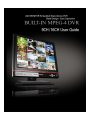
UX User Guide
UX User Manual
Contents
Contents
Before you install
………………………………………………………………………………………… 4
Notice for Installation
Notice
…………………………………………………………………………………… 5
……………………………………………………………………………………………………… 6
SPECIFICATION
………………………………………………………………………………………… 11
Package Contents
……………………………………………………………………………………… 13
System Configuration …………………………………………………………………………………… 14
Remote Controller
HDD
……………………………………………………………………………………… 16
……………………………………………………………………………………………………… 17
USB MEMORY
………………………………………………………………………………………… 18
1. DVR Setup ……………………………………………………………………………………………… 19
1-1. Setup …………………………………………………………………………………………… 19
1-2. Live Mode Setup
…………………………………………………………………………… 21
1-3. Recording Setup ……………………………………………………………………………… 22
1-3-1. Motion Detection Setup …………………………………………………………… 23
1-3-2. Schedule Setup …………………………………………………………………… 23
1-4. Device Setup
………………………………………………………………………………… 25
1-4-1. Alarm Output
1-4-2. Camera Control
……………………………………………………………………… 26
l…………………………………………………………………… 27
1-4-3. PTZF Control
……………………………………………………………………… 27
1-4-4. SPOT Output
……………………………………………………………………… 29
1-5. System Setup ………………………………………………………………………………… 30
1-6. Security Setup
……………………………………………………………………………… 32
1-7. Network Setup ………………………………………………………………………………… 33
1-7-1. Port
………………………………………………………………………………… 34
1-7-2. Network ……………………………………………………………………………… 35
1-8. Recording Device Setup …………………………………………………………………… 37
1-9. Save Setup …………………………………………………………………………………… 38
2. Live Search …………………………………………………………………………………………… 39
2-1. Live Mode ……………………………………………………………………………………… 39
2-2. Search Mode …………………………………………………………………………………… 40
2-3. Playback Mode ………………………………………………………………………………… 42
UX User Manual
3. Archiving Video Into USB Memory Stick …………………………………………………………… 43
3-1. Still Image& Video Recording …………………………………………………………………43
3-2. Video & Still Image Back-up through USB ………………………………………………… 44
4. Firmware Upgrade …………………………………………………………………………………… 46
5. Network Client ………………………………………………………………………………………… 47
5-1.Setup
………………………………………………………………………………………… 47
5-2. Minimum PC requirements for Net Client software ……………………………………… 48
5-3. Installation Program ………………………………………………………………………… 48
5-4. Live Mode ……………………………………………………………………………………… 48
5-4-1. Main Screen
………………………………………………………………………… 49
5-4-2. Main Control Buttons
……………………………………………………………… 49
5-4-3. Search Mode ………………………………………………………………………… 52
5-4-4. Search Control Buttons
…………………………………………………………… 52
5-5. System Setup ………………………………………………………………………………… 55
5-5-1. General
5-5-2. Site
……………………………………………………………………………… 55
…………………………………………………………………………………… 56
5-5-3. Event
5-5-4. Record
………………………………………………………………………………… 56
……………………………………………………………………………… 57
5-5-5. Video ………………………………………………………………………………… 59
5-5-6. About ………………………………………………………………………………… 59
UX User Guide
Before
Beforeyou
youinstall
install
This Manual is for DVR System users.
It is mainly composed of DVR System Design, Name, Connection with Related
equipment such as Pan/Tilt Control, System Program configuration.
☞ Note: We do not take any responsibility of damages resulted from the nonstandardized goods and failures to follow the manual instructions.
☞ Please ask for help to your last seller before disassembling the system for repair and
add particular functions.
FCC Verification
Caution : Any changes or modifications in construction of this device which are not
expressly
approved by the party responsible for compliance could void the user’s authority
to operate the equipment.
Note : This equipment has been tested and found to comply with the limits for a Class A
digital device, pursuant to part 15 of the FCC Rules.
These limits are designed to provide reasonable protection against harmful
interference when the equipment is operated in a frequency energy and, if not
installed and used in accordance with the instruction manual, may cause harmful
interference to radio communications.
Operation of this equipment in a residential area is likely to cause harmful
interference in which case the user will be required to correct the interference at
his own expense.
CE DoC (Declaration Of Conformity)
Warning : This is a class A product.
In a domestic environment this product may cause radio
Interference in which case the user may be required to take adequate measures.
4
UX User Guide
Notice
Noticefor
forinstallation
installation
All of below notices should be verified before installation and operation.
☞ Do not install DVR at moist, dusty and black dirt place.
☞ Do not expose the system to Heaters and a direct ray of light
☞ This system should not be located with magnetic materials and vibrating equipment.
☞ Do not install the system in Hot and Cold place. (Operating Temp 5 °C ~ 40 °C)
☞ Please be careful not to fall a electric conductor into the hole for well-ventilation!
☞ Ensure the power switch is in the OFF position prior to installation.
☞ Make enough space for cable connection.
☞ Install and operate the system in well-ventilated place without vibration.
☞ Note that some malfunction can be happened by Radio or Television
☞ Do not disassemble System.
☞ It the system is connected with power directly, check the ground connection!
5
UX User Guide
Warning/Caution
Warning/Caution
The following describes safety warnings and cautions to protect users and prevent
Property losses. Please thoroughly read the bellow before operating the system.
Warnings and Cautions
If the user is not aware of this
Warnings warning, the user van be killed
seriously injured.
If the user is not aware of this
Cautions caution, the user can be injured or
a property loss may be caused.
Warning
Turn off the system before installing the system.
Do not plug in several electric devices to the
same outlet.
• This may cause heating, a fire, or an electric
shock.
Do not bend the power cable and do not put a
heavy object on the power cable causing a
damage.
• This may cause a fire.
Do not put a liquid container such as water,
coffee, or beverage.
• If liquid is poured into the system, it can
cause a system breakdown or a fire.
Keep the place where the system is installed
always clean after installation. Use dry clothes to
clean the system, but do not use water, thinner,
or other organic solvents.
• This may damage the surface of the system
as well as causing a system breakdown or
an electric shock.
Do not install the system in a humid, dusty, or
soot-covered place.
• This can cause a fire or an electric shock
Do not forcefully pull the power cable or touch
the plug with wet hands. Do not plug in if the
holes on the outlet is too loose.
• This may cause a fire or an electric shock.
6
UX User Guide
Warning
Do not disassemble, repair, or remodel the
system by yourself because a high voltage is
running in the system.
• This may cause a fire, an electric shock, and
injuries.
Install the system in a cool place without direct
sunlight, and keep the temperature properly.
Avoid candle light and heat-generating devices
like a heater. Keep devices and tools away from
a place where a lot of people pass.
• This may cause a fire.
Check if any danger such as a humid floor, an
ungrounded power extension cable, a torn power
cable, or lack of safety grounding. If anything
dangerous is found, ask an assistance to your
dealer or an engineer.
Install the system in a flat place that is not sealed.
Do not stand the system vertically or lean the
system.
• When the system falls down, this may result
in injuries.
• This may cause a fire or an electric shock.
Keep at least 15cm of the distance between the
rear part of the system and the wall. Since the
power cable connection port, image signal
input/output ports, the serial port, the LAN cable
port and external input/output ports are installed
on the rear part of the system, allowing only a
short distance between the wall and the rear part
of the system may have cables bent, damaged, or
cut.
The power outlet must be grounded, and the
voltage range must be within 10% of the rated
voltage. Do not use the same outlet with a hair
dryer, an iron, a refrigerator, or a heating
apparatus.
• This may cause a fire, heating, or an electric
shock.
• This may cause a fire, an electric shock or an
injury.
7
UX User Guide
Warning
When the system battery is dead, replace the
battery with the same type battery or an
equivalent one specified by the manufacturer.
A dead battery should be disposed according to
the manufacturer’s instructions.
• This may cause an explosion.
If the HDD passes its service life, image data
stored in the HDD may not be recoverable. If
broken images are displayed while playing data
stored in the HDD, it means the HDD passed its
service life. When this happens, contact your
dealer or the service center to have it replaced
with a new HDD.
• We are not responsible for deleted data
by user’s carelessness.
8
UX User Guide
Caution
Do not install the system in a place with strong
magnetism, frequencies, or impact, nor near
electric devices such as radios and TV sets.
• Install the system in a place without
magnetic objects, frequencies, or severe
vibration.
Prevent substances from entering into the
system.
Install the system in a place with an appropriate
moisture level and the temperature.
• Install the system in a place with an
appropriate moisture level and the
temperature.
Do not put a heavy object on top of the system.
• This may cause a system breakdown.
• This may cause a system breakdown.
Install the system in a well-ventilated place.
• Keep at least 15 cm of the distance between
the rear part of the system and the wall, and
5 cm of the distance between the side part of
the system and the wall.
Install the system on a stable flat place.
• The system may not properly operate.
9
UX User Guide
Caution
Strong impact or vibration may case a system
breakdown.
The outlet must be grounded.
• Install the system in a place without severe
vibration.
Avoid direct sunlight or an heating
apparatus.
If there is strange sound or smell, unplug the
power cord immediately and contact the service
center.
• This may cause a fire or an electric shock.
Ventilate the air in the system operation room,
and firmly fix the system cover.
• A system breakdown might be resulted in by
inappropriate environments.
In order to keep the system performance, have
your system regularly checked by the service
center.
• We are not responsible for the system
breakdown due to user’s carelessness.
It is recommended to use the Automatic Voltage
Regulator (AVR) for stable power supply.
It is recommended to coil the core-ferrite around
the connector of the system to avoid
electromagnetic interference.
• This is not mandatory, but recommended.
10
UX User Guide
SPECIFICATION
SPECIFICATION
ITEM
Input
Video
Output
Audio
Alarm
UX1009M/UX1016M
Channel
Input Level
9ch/16ch composite 1.0Vp-p, 75 Ohm
Signal Format
NTSC/PAL
Video Loss Check
YES
Monitor Output
1ch VGA
Signal Format
VGA
Input & Output
4ch Line Input & 1ch Line Output
Audio Algorithm
G711
Sensor Input
4ch (NC/NO Selectable)
Alarm Output
4ch
Alarm Output
By Alarm, Motion, HDD Error, Temperature, FAN & POWER
Failure, Video Loss, And ABCD (A Blind Camera Detection)
Compression
MPEG-4
Multi-operation
TRIPLEX (Playback/Record/Network)
MAX. 120fps @ 352x240
NTSC
MAX. 30fps @ 704x480
Frame
Recording
MAX. 100fps @ 352x288
PAL
MAX. 25fps @ 704x576
Recording quality grade
10 grades
Recording Option
Continuous / Schedule / Motion / Manual Recording
Motion Recording Setup
Motion Detection Setup by Grid
Pre & Pos Recording
Yes
Display
NTSC : 30fps/channel, 60 field
PAL : 25fps/channel, 50field
Frame Rate ( /Sec)
안정된 전원 공급을 위해 AVR(자동 전원 공급
기)을 사용하는Multi-Decoding
것이 좋습니다.
1, 4, 9, 16 & PIP
본 기기에 연결하는 커넥터에는 EMI에 영향을
Fast
줄 수 있으므로,
Core-Ferrite(자기 코어)를
Playback
Playback
X 2, 4, 8, 16, 32 MAX
Forward
Speed
감아서 사용하는
것이 좋습니다.
Reverse
y 권장 사항으로, 필수 사항은 아닙니다.
Search Mode
Time, Event, Channels
11
UX User Guide
ITEM
Internal
HDD
Network
UX1009M/UX1016M
Interface
Type
EIDE/ATA133
Max
Capacity of
1HDD
250GB
Max HDD
Number
2
File system
Backup
User I/F
Serial port
Network
Network
Client S/W
Additional
Functions
NaFS : Own developed & Designed for never broken by any
Power failure
USB 2.0
Memory stick
& CD-RW
Still Image & AVI
Network
Moving picture & Still Image
Menu Display
GUI
Input Method
Front keypad, Remote controller
Console & External
Modem
1 RS-232C (9pin D-SUB connector)
Camera control
1 RS-485/422 (4 Terminal Block)
Dynamic IP support
Yes
Network Interface
10/100 base-T Ethernet (RJ-45)
Functions
Live, Search, Backup, PTZF Camera Control
Central Monitoring
System
Yes
DLS( Day Light Saving)
Yes
Multi-Language
Yes
S/W Upgrade
USB memory stick, Network
ELECTRONI
ADAPTOR
CA안정된
L
전원 공급을 위해 AVR(자동 전원 공급
SPECIFICA
기)을 사용하는CONSUMPTION
것이 좋습니다.
TION
본 기기에 연결하는 커넥터에는 EMI에 영향을
줄 수 있으므로,
Core-Ferrite(자기 코어)를
ENVIRONM
TEMPERATURE
ENT감아서
AL
사용하는 것이 좋습니다.
SPECIFICA
y 권장 사항으로, 필수 사항은 아닙니다.
DIMENSION
TION
SIZE
Input: AC100-240V, 50/60Hz, 1.5A
Output : DC12V 5A
About 25W
5°C ~ 40°C
388(W) X 170(D) X 430(H)mm
12
UX User Guide
Package
PackageContents
Contents
Please check the below listed contents prior to installation!
If there is missing content, Please contact your original seller!
Power Cable
CLIENT SOFTWARE CD
DC 12V ADAPTOR
MANUAL
Video Cable
12
UX User Guide
Configuration
Configuration
Camera CH
And CH
Division
Monitor
Power
System
LED
Playback
Buttons
MANU/SEARCH/PTZ/AUDIO/ESC
Button
Camera in 9ch & 16ch
………
Remote
Control
Led
Direction
and
Selection
button
USB
Connector
Alarm out 4ch
Alarm in 4ch
DC12V
RS232
Audio in 4ch
Audio out 1ch
PTZ
Remote PC
13
UX User Guide
PTZ Diagram
RS422
TX +
TX RX +
RX -
RS485
Switches
#2 ON
TX+/RX +
TX-/RX -
Switches
#2 OFF
Sensor Diagram
Sensor #1
Sensor #2
Sensor #3
GROUND
GROUND
Sensor #4
Alarm Connection
Alarm #1
Alarm #2
Alarm #4
Alarm #3
15
UX User Guide
Remote
RemoteController
Controller
Button
Fuctions
POWER
Power On/Off
DISPLAY
Display Mode
F/REW
Play Backward by 60 Sec
PLAY
Playback
F/ADV
Play Forward by 60 Sec
FREEZE/CAP
Freeze and Still Image Recording
FF
Play Forward up to 32 Times
ALARM
Alarm Setup
SETUP
Main Menu
ARCHIVE
Recording List
AUDIO
Select Audio
LOCK
Lock
SEQ
Sequence
RECORD
Manual Recording
SEARCH
Recording Data Search
Arrow Button
Change Menu and Channel No
ID
DVR ID Input
(ID Button+2 Digit Number)
ESC
ESC
PTZ
PTZ Camera Control
NUMBER
Channel 1 to 9
+10
Channel 10 and channel 11 to 16
10CHÎpress + 10 and number 0
11CHÎpress + 10 and number 1
12CHÎpress + 10 and number 2
13CHÎpress + 10 and number 3
14CHÎpress + 10 and number 4
15CHÎpress + 10 and number 5
16CHÎpress + 10 and number 6
16
UX User Guide
HDD
HDD
BRAND
Hitachi
Maxtor
CAPACITY
RPM
BUFFER
INTEERFACE
80GB
7200RPM
2M
E-IDE
160GB
7200RPM
8M
E-IDE
250GB
7200RPM
8M
E-IDE
80GB
7200RPM
2M
E-IDE
160GB
7200RPM
8M
E-IDE
250GB
7200RPM
8M
E-IDE
80GB
7200RPM
2M
E-IDE
160GB
7200RPM
2M
E-IDE
80GB
7200RPM
2M
E-IDE
160GB
7200RPM
8M
E-IDE
250GB
7200RPM
8M
E-DIE
40GB
7200RPM
2M
E-IDE
80GB
7200RPM
2M
E-IDE
160GB
7200RPM
2M
E-IDE
250GB
7200RPM
2M
E-IDE
Samsung
Western Digital
Seagate
15
UX User Guide
USB
USBMEMORY
MEMORY
Maker
Model Name
Speed
Capacity
TRANSCEND
JF Series
1.0/2.0
Up to 4GB
PRETEC
Tiny Series
1.0/2.0
Up to 4GB
Absolline
Zibn2.0 Series
1.0/2.0
Up to 4GB
LG
Xtick Series
1.0/2.0
Up to 4GB
SANDISK
Cruzer Micro
Series
1.0/2.0
Up to 4GB
IOCELL
CELLDISK2.0
Series
1.0/2.0
Up to 4GB
Samsung
Electronics
SUB Series
1.0/2.0
Up to 4GB
Imation
Iflash-ex Series
1.0/2.0
Up to 4GB
HP S100
S100 Series
1.0/2.0
Up to 4GB
Sony
Micro Vault
Series
1.0/2.0
Up to 4GB
Note
Uninstall shielding Software
• DVR may be not compatible with a unlisted USB Memory Stick.
• So, above listed USB Memory Sticks are recommended
16
UX User Guide
DVR
DVRSetup
Setup
1. DVR Setup
Change the default setup for your application.
1-1. Setup
Press “1111” (Default Password) with pushing “CH1” Button four times to enter into Main
Menu.
[Picture 1-1] Configuration Menu
☞ [Reference]
This Manual is edited mainly for Remote Controller.
17
UX User Guide
SETUP
LIVE
RECORD
DEVICE
OSD
SEQUENCE
SEQ-DWELL TIME
OSD CONTRAST
CHANNEL
RESOLUTION
CHANNEL
FRAME RATE
QUALITY
RECORDING
MOTION ZONE
MOTION SENSITIVITY
SENSOR RECORDING
PRE RECORD
POST EVENT RECORD
AUDIO
SCHEDULE
ALARM-OUT
ALARM OUT
PTZ
CH
NAME
SPEED
ID
SPOT-OUT
SPOT TYPE
SPOT ON EVENT
SPOT EVENT DWELL TIME
SEQUENCE
SEQ-DWELL TIME
SPOT CHANNEL
KEY TONE
REMOTE CONTROL ID
SENSOR
SYSTEM
DISPLAY
BRIGHTNESS
CONTRAST
HUE
SATURATION
DVR ID
DESCRIPTION
LANGUAGE
LOAD FACTORY DEFAULT
LOAD DEFAULT
DATE FORMAT
SET DATE&TIME
SECURITY
ADMIN PASSWORD
USER PASSWORD
NETWORK PASSWORD
NETWORK
PORT
CLIENT ACCESS
BANDWIDTH SAVING
NETWORK TYPE
SENSOR IN
MOTION ON
VIDEO LOSS ON
ALARM DURATION
TYPE
HARDWARE VERSION
SOFTWARE VERSION
STORAGE SIZE
IP ADDRESS
MAC ADDRESS
DAYLIGHT SAVING
IP
SUBNET MASK
GATEWAY
DNS
DDNS
SEND E-MAIL
STORAGE
OVERWRITE
FORMAT
DISK INGO
18
UX User Guide
1-2. Live Mode Setup
Set the values for live display. Navigate through the menu items with pressing the UP
or DOWN button. The values of the menu item may be changed with pressing the LEFT
or RIGHT button.
[Picture1-2] Live Mode Setup Screen
Item
OSD
SEQUENCE
SEQ-DWELL TIME
Description
Enable/disable on-screen-display.
Enable/disable SEQ button
Set the dwell time for each, 4 or 9 channels display in sequential display mode.
OSD CONTRAST
Set the visibility level of the On Screen Display (OSD)
CHANNEL
Select the channel for applying the following settings.
Press SELECT to change channel name.
DISPLAY
BRIGHTNESS
CONTRAST
HUE
SATURATION
Enable/disable display of the video channel in live display mode
Change the brightness value for the specified channel
Change the contrast value for the specified channel
Change the hue value for the specified channel
Change the saturation value for the specified channel
[Table1-2] Live Mode Setup
21
UX User Guide
1-3. Recording Setup
Set the values for recording video. Navigate through menu items by pressing the UP or
DOWN button. User can change the value of the menu item by pressing the LEFT or
RIGHT button.
[Picture1-3] Recording setup screen
Item
RESOLUTION
CHANNEL
FRAME RATE
Description
Set the resolution to 704x480, 704x240, or 352x240(NTSC).
Select a channel for applying the following settings.
Set a recording Frame rate channel by channel.
Max 120fpt Recording at 352x240, Max 30fps Recording at 704x480
QUALITY
Select a recording quality for the specified channel from Network, Standard, High,
Super or Ultra
RECORDING
Set a recording mode for each channel. Select one of Continuous, By Motion, By
Sensor, By Schedule or Disable.
MOTIONZONE
Select Full Zone or Partial Zone for motion sensing.
MOTION SENSITIVITY
Set the motion sensitivity for the specified channel. Control the motion sensitivity
from 1 to 9.
SENSOR RECORDING
Record a video when Sensor trigger.
PRE RECORD
POST EVENT RECORD
AUDIO
SCHEDULE
5 Sec of Pre-event Recording from Event is triggered (Motion, Sensor)
Set post event recording time duration for the specified channel
Audio ON/OFF for each channel.
Enable/disable audio for the specified channel
[Table1-3] Recording setup menu
22
UX User Guide
1-3-1. Motion Detection Setup
By selecting Partial Zone in the Motion Zone menu, user can set-up the motion
sensing zones in the screen. Move around each rectangular zone using 4 direction
key buttons and press SEL button to include the rectangular region as part of the
motion sensing zone. The rectangular blocks included as part of the motion zone are
indicated by changing the color of the blocks.
[Picture1-3-1] Motion Zone selection screen
1-3-2. Schedule Recording
You can select a type of recording (Motion, Sensor, Continuous) at one hour interval for one
week.
Buttons
REW
F/REW
PLAY/PAUSE
FF
Description
Use to set Continuous recording mode. Î C
Use to Disable recording setting.
Use to enable Motion detection triggered recording. Î M
Use to enable Sensor triggered recording Î S
Go Up
Go Right
23
UX User Guide
Buttons
Description
Go Down
Go Left
Exit from the Schedule Menu
[Table1-3-2] Buttons for schedule Recording
[Picture1-3-2] Schedule recording setup
24
UX User Guide
1-4. Device Setup
Set the values for device setting. Navigate through menu items by pressing the UP or
DOWN button. User can change the value of the menu item by pressing the LEFT or
RIGHT button.
[Picture1-4] Device setup screen
Menu
ALARM-OUT
PTZ
SPOT-OUT
KEYTONE
REMOTE CONTROL ID
SENSOR
Description
Set the sensor, motion, and video loss for each alarm.
Set the camera speed, number, type and ID
Select channel for spot monitoring
Enable/disable key tone
Select a remote controller ID (No. 0~99 Selectable)
Select a sensor number and type
[Table1-4] Menu in Device Setup
25
UX User Guide
1-4-1. Alarm Output
Item
Description
ALARM OUT
Select a alarm output number (No.1~4 Selectable)
SENSOR IN
Select a sensor input (No.1~4)
MOTION ON
Select a motion sensor (No.1~4)
VIDEO LOSS ON
ALARM DURATION
Select a video loss channel (No.1~4)
Setup a alarm duration. (1~60Sec)
[Table1-4-1] Device Setup
[Picture1-4-1] Device Setup
26
UX User Guide
1-4-2. Camera Control
This is to control a camera through RS-485 Port.
Select channel No for camera control.
Select a type of camera and setup speed and camera ID
[Picture1-4-2] Camera Control
1-4-3. PTZF Control
Select “PTZ” button on front panel of DVR after completion of Camera Setup.
Setup menu for your application.
27
UX User Guide
[Picture1-4-3] PTZF Control
Item
PAN/TILT
ZOOM/FOCUS
INITIALIZE
Description
Up and Down button for Tilt and Left/Right button for Pan
Up and Down button for Zoom and Left/Right button for Focus
To initialize the camera setting
[Table 1-4-3] PTZF Control Button
28
UX User Guide
1-4-4. SPOT Output
This page explains functions of SPOT output.
[Picture 1-4-4] SPOT Output
Item
SPOT TYPE
SPOT ON EVENT
SPOT EVENT DWELL
TIME
SEQUENCE
SEQ-DWELL TIME
SPOT CHANNEL
Description
Select type of SPOT (Full or 4Screen)
Setup spot on Event
Setup SPOT Event Dwell Time
Setup sequence mode
Setup SEQ-DWELL TIME
Select channel of SPOT Output
[표1-4-4] SPOT Output Menu
29
UX User Guide
1-5. System Setup
Setup Name. Information, Date of System.
[Picture1-5] System Setup
Item
DVR ID
DESCRIPTION
LANGUAGE
LOAD FACTORY
DEFAULT
Description
Make a name of DVR with UP/DOWN/LEFT/RIGHT Buttons
System Information (Version, HDD Capacity, IP Address, MAC Address)
Select a language
Initialize all of the Settings
LOAD DEFALT
Go to factory default
(Except for Password, Date Format, DLS, Network Setup, HDD Overwrite )
DATE FORMAT
Year/Month/Date format setup
SET DATE&TIME
Date and time of auto rebooting setup
Summer time Setup
[Table1-5] System Menu
30
UX User Guide
[Picture1-5-1] ID Setup
[Picture1-5-2] System Information
[Picture1-5-3] Summer Time Setup
[Picture1-5-4] Date/Time Setup
31
UX User Guide
1-6. Security Setup
In this menu, password and security parameters can be input. Navigate through the
menu items by pressing the UP or DOWN button. User can change the value of the
menu items by pressing the LEFT or RIGHT button.
[Picture 1-6] Security Setup
Item
Description
ADMIN PASSWORD
Authorize all of menu setting. Default P/W:1111
USER PASSWORD
Authorize the specified menu setting by Administrator
NETWORK
PASSWORD
Password for DVR monitoring through network.
Default P/W “1111”
[Table1-6] Security Menu
32
UX User Guide
1-7. Network Setup
Network parameters can be input in this screen. These parameters are used for remote
clients who are connected to the DVR over the network.
[Picture1-7] Network Setup
Item
Port
Description
Port Number (Default : 5445)
Client Access
Authorize Client Access through Network
Select “ON” for Access from Remote Area
BANDWIDTH
SAVING
Select “OFF” for data transmission under Low Bandwidth
Network Type
Select one of the network types (LAN, ADSL, DHCP)
DHCP
DHCP
Select “DHCP” for Dynamic IP connection
ADSL
ID : Register “ID” for ADSL Connection
Password : Register “ID” for ADSL Connection
LAN
IP : Register “IP Address for your application.
GATEWAY : Register gateway number for your application.
SUBNET MASK : Register subnet mask number for your application.
33
UX User Guide
Item
DDNS
Description
DDNS Setup is used to get Domain Address after DDNS Server registration.
When “DDNS” is turned on, DDNS Server Name is displayed for Domain
Registration.
DDNS Sever Name : “ns.umbddns.com Æ Factory Default
Domain Name is used for Network Connection . (IP Address Available)
And, Bar Code number on the back side of system must be registered.
Ex) xxxx.umbddns.com is created and “umbddns.com” is uneditable.
But, “xxxx” is editable .
[Table1-7] Network Menu
[Note]
MAC Address (SystemÆ System Information) should be registered on our company’s server.
If not registered, DDNS cannot be used.
1-7-1. Port
When connecting 1 or more DVRs to a network through an IP sharing device, each
device must have a unique RTSP port number for access to each unit from outside
the LAN. Also, the IP sharing device must be conPictured for port forwarding, so that
each port, when accessed on the IP sharing device, will forward to the appropriate
DVR. This port number is listed next to the Port menu option in the NETWORK menu.
If the user plans to only access the units from within the same local area network,
the RTSP port does not have to be changed.
IP Router
When DMZ Setup or Port forwarding is used, three port numbers must be set for port forwarding.
Example) if 5445 is selected as a port number, Both 5446 and 5447 must be registered.
Please refer to the manual of your router because each router has a different port forwarding way!.
34
UX User Guide
1-7-2. Network Type
Select a type of Network
LAN
This is used for Network Connection through Static IP, DMZ configuration of Router or Port
Forwarding.
Network Configuration
1. Static IP (Refer to Network Manager)
2. ADSL Connection through Router
With using “DMZ” function in IP Router, Router itself gives Static IP.
Input the created IP Address on DMZ to "IP" and ADSL's IP Address to "Gateway"
for Same Subnet mask and DNS Address as IP Router should be input.
Item
IP
GATEWAY
SUBNET MASK
DNS
Description
The fixed IP address of the DVR
The IP address of the gateway
The subnet mask for the LAN
Set the DNS IP.
[Picture1-7-2] LAN Menu
DHCP
This setup is used with dynamic IP not static IP.
Every IP address is granted automatically under the dynamic IP network.
(This is not a permanent IP but a granted IP whenever network connects, which means DHCP)
ADSL
ADSL line supplied by Network Service Company is used.
(PPPoE Network)
(ID, P/W necessary for connection)
35
UX User Guide
Item
ID
PASSWORD
Description
The user ID for ADSL connection
The password for ADSL connection
[Table1-7-3] ADSL
DDNS
MAC Address granted to each system (12 digit number or Mac address in system information)
must be registered to DDNS Server to get a domain address.
Regardless any change of Network IP, You can connect a network with a registered domain
name.
(Example : domain name is like “xxxx.umbddns.com” and “umbddns.com” is uneditable)
DDNS Server Name : ns.umbddns.com. This is unchangable
36
UX User Guide
1-8. Recording Device
User can set recording mode in the hard disk drive or initiate format of the
hard disk driver.
[Picture1-8] Recording Device
Item
OVERWRITE
FORMAT
DISK INFO
LOAD SETUP FROM
A USB
SAVE SETUP TO A
USB
Description
Overwrite existing material when hard disk drive is full.
Format all of stored data in HDD
Information such as capacity, usage, recording times, and others of all HDD
installed in DVR.
Load the settings to DVR from USB
Save the settings in DVR through USB
RECORD LIMIT
Select a period of recording
RECORD LIMIT
DAYS
Setup Recording Period
[Table1-8] Recording Device Menu
37
UX User Guide
1-9. Save Setup
Save the changed Setup Menu
If Save Setup is not selected, the changed setup doesn’t record after system rebooting
[Picture1-8] Save Setup
38
UX User Guide
Live
LiveSearch
Search
2. Live Search
2-1.
Live Screen
Show Live Images by Cameras and information
of each channel, HDD Capacity and
Recording
[Picture2-1] Live Screen
Icon
Description
Continuous recording in progress
Manual recording in progress
Motion recording in progress
Sensor Recording in progress
Event Recording for each channel in progress
Indicates that alarm output is activated.
Indicates that a network client is connected to the DVR.
Indicates that sequencing mode is enabled.
[Table2-1] Live Screen Icon
39
UX User Guide
Button
SETUP
SEQ
PLAY/PAUSE
Description
Launch the SETUP menu.
Enable/disable the automatic sequential display in full or quad mode.The channel
display in quad mode is followed the settings in the setup menu.
Launch the SEARCH window.
Direction buttons (UP/DOWN/LEFT/RIGHT)
SEL
Switch between full screen and current display mode.
ESC
Cancel Setup Menu
REC
Select for manual recording for all channels.
[Table 2-1-1] Live Screen Button
2-2. Search Screen
If User push PLAY/PAUSE button on live mode, below picture(2-2) shows.
Red Color of Date indicates a recording data.
Select a red color of date and channel no and recording type (A : All, M : Motion,
S : Schedule, R : Pre-Recording, C : Continuous).
[Picture2-2] Search Picture
40
UX User Guide
Event Search
1.Select PLAY/PAUSE button and a date for search.
2. Push “SEL” Button
3. Below search menu shows
4. Recording type (A : All of Recording Data Search, M : Motion Recording Data Search,
S : Sensor Recording Data Search, R : Manual Recording Data Search,
C : Continuous Recording Data Search
5. Recording type shows on search bar, Go to your demanding channel no or all for search.
6. If “ESC” button is selected during playback, it returns to search menu.
7. Keep pushing “ESC” button to go back to live mode
[Picture2-2-1] Search List
41
UX User Guide
2-3. Playback
Picture [2-3] shows all channels of the playback images.
“ESC” Button makes it back to the previous.
[Picture2-3] Live Picture
Button
Description
ESC
Return to the previous menu screen or exit from the setup menu
REW
Press to rewind video at 1x, 2x, 4x, 8x speed.
Press “PLAY” button to go back to normal speed playback.
F/REW
PLAY/PAUSE
F/ADV
FF
Jump/Step backward. The playback position moves 60 seconds backward.
Press to play or pause recorded video.
Jump/Step forward. Playback position moves 60 seconds forward.
Press to fast forward video at 1x, 2x, 4x, 8x speed.
Press “PLAY” button to go back to normal speed playback.
Use to select channel 1to 4 in full screen mode or to change the quad display by
using the LEFT or RIGHT button.
The channel display in quad display mode is followed the setting in the setup menu.
SEL
FREEZE/CAPTURE
Switch between full screen and current display mode.
Press “FREEZE/CAPTURE “ to record Video & still image through USB
[Picture2-3] Live Picture Icon
42
UX User Guide
Archiving
ArchivingVideo
VideoInto
Into
USB
Memory
Stick
USB Memory Stick
3. Archiving Video Into USB Memory Stick
To archive a still image or video to a USB storage device, user must first capture a
still image or video to a hard disk drive.
3-1. Video & Still Image Recording
Still Image Recording can be archived on both Live Mode and Playback Mode.
Press “FREEZE/CAPTURE” button to finish a recording.
Refer to [Picture 3-1]
[Picture 3-1] Still Image Recording
Still image archive
Still image can be captured and stored into the hard disk drive during live mode or while
playing back recorded video.
During live mode and playback mode, press FREEZE/CAPTURE button twice to capture and
store the still image. Once you press the FREEZE/CAPTURE button twice, the screen shown
in Picture 5.1.1 will be displayed.
The still image will be stored into the hard disk drive and can be transferred to the USB
storage device later.
Video archive
Video can be archived and stored into the hard disk drive during playing back recorded video.
During playback mode, press the FREEZE/CAPTURE button to launch the archiving function.
The system will ask whether to store still image or video.
If the user selects still image, it will store captured image into the hard disk drive.
If the user selects video, it will store video into the hard disk drive. When a USB storage
device is plugged in and archiving to the USB is requested, the system will convert the
corresponding portion of the video into an AVI file and store it on the USB storage device.
43
UX User Guide
3-2. Video & Still Image Back-up through USB
Connect USB memory stick to USB port
Press “ARCHIVE” button to select a date on the calendar.
Select a red color of date including recorded data with “SEL” button.
[Picture3-2] Still Image Search
After selecting data for USB Backup, Year/Month/Date/Time shows on the screen.
Select “FREEZE/CAPTURE” button and choose “USB Memory” or “CD-RW” for backup.
List for Backup
Still Image File
44
UX User Guide
USB Recording
CD-RW Recording
Video for backup is recorded as AVI File.
If you fail to play backup data, please install a codec program.
http://www.divx.com/divx/download/
45
UX User Guide
Upgrading
UpgradingFirmware
Firmware
4. Upgrading Firmware
It is possible to upgrade Firmware through USB.
Make “upgrade” folder in Memory stick and put a new firmware.
(app9.bin(9CH Firmware), app16.bin(16CH Firmware))
1. Press [SETUP] button and input a password. (Default P/W “1111”.)
2. Go to the SECURITY and select the ADMIN PASSWORD.
3. Enter the password as 12341234, and press the SEL button.
4. After auto rebooting, Test Program is activated.
5. Select USB UPGRADE and then the upgrading will start automatically.
6. After the upgrade is completed, select BOOT APPLICATION to reboot DVR.
USB Upgrade
Upgrade in progress
Upgrade Complete
System Return
[Picture 4-1] USB Upgrade
46
UX User Guide
Network
NetworkClient
Client
5. Network Client
The DVR provides a live remote monitoring feature. Remote monitoring requires installation
of a software client program on your PC. A LAN connection using the RJ45 connector on
the rear panel is mandatory for remote connection.
For the local operation purposes, the frame rate is limited to 1 frame/sec when there is
no recording operation in the DVR. When recording is under progress, video frame rate for
the live monitoring will follow the recording frame rate.
[Picture5-1] Main user interface
5-1. Overview
The remote software supports remote live viewing, search, playback and system
configurations.
By installing the UX9/16CH remote software on a Window PC, you can monitor
real-time and recorded images via optional Ethernet network. This includes the ability to
monitor video, playback recorded video and change operating parameters.
47
UX User Guide
5-2. Minimum PC requirements
Minimum
Recommended
Intel Pentium Ⅲ
Intel Pentium Ⅳ
500Mhz
2Ghz
Memory
128MB
256MB
VGA
16MB
64MB
Resolution
1024x768
1024x768
Disk space
10MB
10MB
OS
Windows 2000
Windows 2000,
Professional, XP
Network
10/100Base T
10/100Base T
Others
Direct X 8.1
Direct X 8.1 or Higher
CPU
5-3. Installing the program
1. the provided CD into the CD-ROM drive of your PC.
2. Run
to start the installation process.
3. Double click the
icon to start the program
5-4. Live viewer
When installation is complete, double click the
icon on your desktop to start the
program.
48
UX User Guide
5-4-1. Main Screen
5-4-2. Main Control Button
Button
Description
Displays the current date and time.
Click this icon to connect to the DVR
Menu Screen
IP Address : Input DVR IP address or domain address
Port No : Input port No
Protocol : Select a normal TCP
Password : Input DVR P/W
Click this icon to disconnect to the DVR
49
UX User Guide
Click this icon to search for recorded videos.
Click this icon to see a live video.
Press this button to arm the program
Press this button to disarm the security.
Once you click the lock or unlock icon, this pop up window appears. You need to
remember the pass word and enter the password when you try to operate the client
software.
This button is to control PAN/TILT & ZOOM/FOCUS of Camera.
Click this icon to play live video.
Click this icon to pause live video.
This button is to record Live Image to the computer.
The recorded data is stored in “Storage” Folder as date format.
This button is to record a still image to the appointed folder by USER.
(One channel capture available)
This window pops up on still image recording.
Save Path : Appoint the folder for saving
File : Appoint a name of file for saving.
File Format : Appoint a file format for saving.
BMP or JPG selectable
50
UX User Guide
Click this icon to setup configuration of client software.
Click this icon to exit from the operations of client software.
Alarm indicators for each channel.
Full screen
Quad screen
9 Split screen
16 Split screen
Click this icon for Sequential display of each channel in full screen mode.
Adjust audio volume
HDD storage Indicator of DVR.
It shows the client connection information.
Max/Min/Exit of the client viewer
51
UX User Guide
5-4-3. Search Mode
Press Search Button to show below window.
5-4-4. Search Control Button
Button
Description
Displays the recording time of the selected data by adjusting of scale in the middle
of the bottom of the main user interface.
Click this icon to see live videos.
Click this icon to exit from the operations of client software
Click this icon to capture a still image of recorded video.
52
UX User Guide
Save Path : Appoint the folder for saving
File : Appoint a name of file for saving.
File Format : Appoint a file format for saving.
(BMP or JPG selectable)
Click this icon to set the beginning time for backup of the recorded video in AVI
format
Click this icon to set the ending time for backup of the recorded video in AVI
format
Click this icon to backup the recorded video in AVI format.
The calendar shows dates with recorded video in a light blue and the selected date
in dark blue.
The timeline shows recorded data in dark blue on the bar. You can adjust the time
line scale and move it to the time you wish to playback. Then click the play icon to
display the recorded video.
Click to play the recorded video.
Click to pause the displayed video.
Click to fast forward the video at 2x and 4x speeds in playback mode.
Click to rewind the video at 2x and 4x speeds in playback mode.
Click to reverse 1 frame.
53
UX User Guide
Click to advance 1 frame.
Quad screen
9 Split screen
16 Split screen
Left/Right Button is to search every 1hour data.
Middle of button is to change the selected one hour to 60 minutes.
Show a recording data volume in DVR
54
UX User Guide
5-5. System Setup
Press
to enter into Setup Menu.
5-5-1. General
Security Option
This option is to protect any unauthorized approach with P/W Setup.
Password Setup Menu
Save Path
Select a folder to save each setting.
Miscellaneous
Automatic reconnection Menu
This option is connect with network automatically on Network delay or disconnection.
Display Network statistics
This is to show a network speed.
55
UX User Guide
5-5-2. Site
User can change a name of each site.
5-5-3. Event
This saves each event to the appointed file.
56
UX User Guide
Event search
This show a log history on date.
5-5-4. Record
This is to set a record option of each channel.
(This is not DVR recording option but client program recording option.
Always Æ Continuous Recording, Event Æ Motion or Sensor Recording, Auto Record
Æ Auto Recording on program start
Recording time setup is available with “Motion” or “Alarm” Setup on Event Recording Setup.
57
UX User Guide
This recording option indicates a current status of recording setup of DVR.
Disk
You can select the local disk to use and the amount of disk space you want to allow
the program to use for recording. You can also select the option to overwrite data or
stop recording when the maximum amount of disk space is full.
58
UX User Guide
5-5-5. Video
This page is to match colors of client program.
(This is supported depending on a installed video card in personal computer.)
5-5-6. About
“About” provides network client version information.
59