1
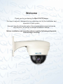
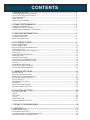
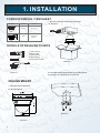
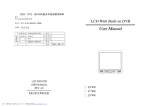
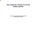
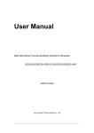
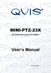
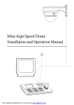
®
MINI-PTZ-12X
12X OPTICAL ZOOM PTZ DOME CAMERA
USER'S MANUAL
© Copyright Qvis® All documentation rights reserved.
Version 1.0 11/2013
Welcome
Thank you for purchasing the Mini 12X PTZ dome
This user's manual is designed to be a reference tool for the installation and
operation of your system.
Here you can find information about the corresponding camera's features
and functions, as well as a detailed installation method.
Before installation and operation please read the following safeguards
and warnings carefully!
IMPORTANT SAFEGUARDS AND WARNINGS
1.ELECTRICAL SAFETY:
l
l
l
All installation and operations here should conform to your local electrical safety codes.
We assume no liability or responsibility for all the fires or electrical shock caused by improper handling or
installation.
We are not liable for any problems caused by unauthorized modification or attempted repair.
2.TRANSPORTATION SECURITY:
l
l
No heavy stress, violent vibration or contact with water is allowed during transportation, storage and
installation.
Please use the original packing material (or the material of the same quality) when you ship it back to the
manufacturer.
3. INSTALLATION:
l
l
Do not apply power to the product before completing installation.
Do not put object(s) on the product.
4. ENVIRONMENT
l
l
l
l
l
This product should be installed in a cool, dry place away from direct sunlight, inflammable, explosive
substances and etc.
Please keep it away from environments that contain electromagnetic radiation or objects that produce it.
Please keep sound ventilation around the device at all times.
Do not allow the water and other liquid to penetrate into the device if casing has been compromised. This
series product complies with the IP66 standard specified in the Degrees of Protection Provided by
Enclosure.
Please make sure the CCD (CMOS) component is away from the radiation of the laser beam device.
Otherwise it may result in CCD (CMOS) optical component damage.
5. DAILY MAINTENANCE
l
l
l
Do not touch CCD (CMOS) component. You can use the blower to clean the dust on the surface of the
device. You can use the dry cloth with some alcohol or mild detergent to clear if necessary.
Do not use volatility solvent such as the benzene or thinner, or detergent with strong abradability. It may
result in lens damage or it may adversely affect the device performance.
If there is too much dust, please use the water to dilute the mild detergent first and then use it to clean the
device. Finally use the dry cloth to clean the device.
6. ABOUT ACCESSORIES
Always use all the accessories recommended by manufacturer.
Before installation, please open the package and check that all the components are included in the package.
Contact your local retailer ASAP if something is missing in your package.
CONTENTS
1. INSTALLATION-------------------------------------------------------------------- 2
- CORRESPONDING ITEM SHEET-------------------------------------------------------------------2
- DETAILS OF RELEVANT PARTS--------------------------------------------------------------------2
- CEILING MOUNT --------------------------------------------------------------------------------------2
- WALL MOUNT-------------------------------------------------------------------------------------------3
- INSTALLING CAMERA--------------------------------------------------------------------------------3
2. DOME PERFORMANCE----------------------------------------------------------5
- DOME PARAMETERS---------------------------------------------------------------------------------5
- CAMERA SPECIFICATIONS-------------------------------------------------------------------------5
- DOME PERFORMANCE & FEATURES-------------------------------------------------------------6
3. FEATURE INFORMATION -------------------------------------------------------7
- AUTO-RUN MOTION----------------------------------------------------------------------------------7
- CAMERA CONTROL-----------------------------------------------------------------------------------7
-MONITOR FUNCTION---------------------------------------------------------------------------------8
4. SYSTEM SETTINGS---------------------------------------------------------------9
- BASIC OPERATION------------------------------------------------------------------------------------9
- EDIT DOME LABEL ------------------------------------------------------------------------------------10
- INITIAL DISPLAY INFORMATION-------------------------------------------------------------------11
- DISPLAY SETUP---------------------------------------------------------------------------------------12
- SYSTEMATIC MOTION CONTROL-----------------------------------------------------------------13
- AUTO FLIP----------------------------------------------------------------------------------------------13
- SPEED PROPORTION PAN--------------------------------------------------------------------------13
- PARK ACTION------------------------------------------------------------------------------------------14
- POWER UP ACTION-----------------------------------------------------------------------------------14
- FAN START UP TEMPERATURE--------------------------------------------------------------------14
- HEAD UP MOUNTING SETTING--------------------------------------------------------------------14
- CLEAR---------------------------------------------------------------------------------------------------15
- PASSWORD SETTINGS -----------------------------------------------------------------------------16
- DATE & CLOCK SETTINGS--------------------------------------------------------------------------17
- SETUP DOME PARAMETER-------------------------------------------------------------------------18
5. CAMERA SETTINGS--------------------------------------------------------------19
- ZOOM SPEED-------------------------------------------------------------------------------------------19
- DIGITAL ZOOM CONTROL---------------------------------------------------------------------------20
- BACK LIGHT COMPENSATION----------------------------------------------------------------------21
- SLOW SHUTTER CONTROL-------------------------------------------------------------------------22
- IR CUT FILTER------------------------------------------------------------------------------------------23
- ADVANCED SETTING---------------------------------------------------------------------------------24
- AE MODE------------------------------------------------------------------------------------------------24
- WHITE BALANCE MODE-----------------------------------------------------------------------------25
- CAMERA MENU SETTING----------------------------------------------------------------------------25
6. FUNCTION SETTING--------------------------------------------------------------26
- PRESET SETTING-------------------------------------------------------------------------------------26
- SCAN-----------------------------------------------------------------------------------------------------27
- PATTERN------------------------------------------------------------------------------------------------28
- TOUR-----------------------------------------------------------------------------------------------------29
- ZONE SETTING----------------------------------------------------------------------------------------30
- TIME RUNNING SETTING----------------------------------------------------------------------------31
7. PRIVACY ZONE MASKING-------------------------------------------------------32
8. APPENDIX---------------------------------------------------------------------------33
- DOME MENU INDEX-----------------------------------------------------------------------------------33
- TROUBLE SHOOTING--------------------------------------------------------------------------------34
- CLEANING THE CLEAR DOWN COVER-----------------------------------------------------------34
- Rs485 BUS BASIC KNOWLEDGE -------------------------------------------------------------------35
1
1. INSTALLATION
CORRESPONDING ITEM SHEET
Mount
Picture
Place
Ceiling
Indoor only
Wall
Indoor and
outdoor
1. Get the products out from the packages.
As Picture 3
DETAILS OF RELEVANT PARTS
1
2
1.wall bracket
2.base board
3.power cable
4.speed dome
5.transparent cover
3
Picture 3
4
5
2. Drill holes and fix base board on the ceiling floor
by using the 3 x M4 bolts.(Like picture 4
Picture 1
CEILING MOUNT
1. Dimensions of product
as shown below:
Picture 4
Picture 2
2
1. INSTALLATION
3. Insert three screws in the mini dome into the
apertures on the base board (please refer to 1),
then turn 15 degrees in clockwise (please refer to 2).
WALL MOUNT
Dimension of product are shown in the
picture below
250
174
②
①
Picture 5
Picture 8
4 . Use 3 additional M3*5 screws tightly fix camera
into ceiling.
INSTALLING CAMERA
1. Get the products out from the packaging.
As shown in picture 8 below.
Picture 6
5. Connect the power cable, video cable and
RS485 control-cable. See picture below.
Video end
Green
Yellow
Power port
Picture 8
Picture 7
3
1. INSTALLATION
2. Make the wall bracket match the model on
installation wall, and draw the central position of
the drill hole. (As picture 2.2-2)
100£00
75£00
Picture 11
Picture 9
3. Please drill four installation holes for the M8
expanding metal screw with the lashed electric drill
on the installation surface, and be sure that the
installation hole is approximately 75mm in depth.
Expand M8 metal screw. (As shown in picture 10).
5. Please make the wall bracket aims at the M8 screw,
so that the output cable will be locked into the hole of
motherboard bracket, and use the M8 screw to lock
the wall bracket tightly. As seen in picture 11 above.
Picture 12
Picture 10
6. Connect the power cable, video cable and RS485
control-cable. As shown in picture 12 above.
4. Thread the water-proof output cable of mini
dome through the wall bracket, and insert the
three screws from the cover board and mini
dome into the aperture on the base board, then turn
15 degrees clockwise. Be sure that central
position of the two ear holes of base board and cover
board are matched, and then lock it tightly using
the additional M3*5 screw.
4
2. DOME PERFORMANCE
DOME PARAMETERS
Setting
Power supply
Power supply
DC12V
Baudrate£RS485£
Cosumption
12W
Communication Protocol
0-255
Physical
Built-in
Pan rotation
Pelco-D/Pelco-P/Samsung/
Panasonic
ID setting
Operational
Decoder
2400/4800/9600/19200bps
360°
Operation temperature
-10°C to +50°C
Tilt 90°- with auto-flip
Environmental humidity
0.95%(no condensation)
Rotation speed
Pan1°- 200°/S
Tilt1°-150°/S
Mount way
Wall mount/Ceiling
Preset
128
Wall mount
N:2.2kg
G: 2.8kg
N: 1.4kg
G: 1.8kg
Tilt rotation
Monitor way
Preset/tour/scan/
pattern
Ceiling mount
Speed
Limitless variable-speed controlling
Material
Aluminum, iron and carbon alloy, plastic alloy
CAMERA SPECIFICATIONS
Specification/parameter
Model
Imaging Element
1/4"CCD
Scanning System
625lines, 50field/s
White Balance
Auto/manual
Gain Control
Auto Gain Control
S/N
¡50dB
Shutter
Auto: 1/50-1/120,000 s continuously/manual
Lens
10 times optical magnified lens
Magnification
100times (10 times optical X 10 times digital)
Video Output
Multiple Video Output, 1.0Vp-p
Environmental Temperature
-10°C to +50°C
Environmental Humidity
0~90%(no condensation)
5
2. DOME PERFORMANCE
DOME PERFORMANCE AND FEATURES
This PTZ camera product has the latest technological features with high resolution colour camera and variable-speed
pan/tilt and multifunction decoder. It can reduce the connection and installation process between systematic parts
and also can improve the stability and reliability of the system. Meanwhile it is easy to install and repair, and it has the
following advantages: contemporary shape, smooth rotation, low noise and simple operation.
1. Built-in digital camera
● High sensitivity, high resolution, and integrated digital processing
● Auto-focus
● Auto-Iris
● Auto brightness control
● Auto white balance
● IR cut filter
● Auto back light compensation
● Auto slow shutter
2. Built-in high resolution colour camera with pre-focus lens.
● Pre-focus lens 6mm, 8mm, 12mm(Optional)
● Auto brightness controlling
● Auto white balance
● Auto back-light compensation
● Auto iris
● Auto focus
3. Integrated multi-protocol decoder
● Figure design, all the data is stored in the inside of camera pan/tilt. When the power is turned off, the storage
data cannot be lost.
● Built-in decoder and multi-protocol, includes PELCO-D, PELCO-P, SAMSUNG, PANASONIC and other
mainstream protocols. The protocols can be automatically recognised by the dome and it can choose
corresponding protocol to communicate with host. Manual setup not needed.
● 128 presets can be stored. Supports auto tour(but only can only transfer 1-80 presets), and 1 tour can store up
to 32 presets.
● 4 pattern tour
● 4 scan
● Built-in direction indicator
● Built-in temperature indicator
● Built-in clock setting
● RS485 bus controlling in series, and dome ID;1-255(optional)
4. Built in Pan/Tilt
● Iron and carbon alloy structure, high intensity (good heat dissipation).
● Precise stepping motor, rotates smoothly, reacts sensitivity and orientates accurately.
●Exquisite mechanical drive, support pan 360° continuously and tilts 0-90°, and may rotate180°
with auto flip.
● Rotates slowly as 1°/s pan speed meaning image doesn't jitter.
5. OS D menu
● All the menu option are displayed in English.
● Video OSD menu. It is direct and simple to revise the dome information and parameters via the keyboard and
menu display.
● You can set park action, power up action or arrive an appointed action.
6. Internal temperature test
● W hen the temperature exceeds the upper limit, the screen will display alarm information.
● According to the real-time temperature, an inbuilt fan will keep the temperature stable.
6
3. FEATURE INFORMATION
This section predominantly describes the main functions and general principles of the integrated speed dome,
and does not refer to the integral operation methods.
AUTO-RUN MOTION
Focus/speed proportion pan
When adjusting manually, for focussing on far distances, the dome responds at a high-speed so that touching
rocker slightly may make picture move rapidly, thus causing the picture to become blurred.
The dome automatically adjusts the pan and tilt rotation according to when you are zooming in or out, which
makes it convenient to operate manually and to track an object in the field of view. In the menu, you may
change system parameter setting for proportion pan to ‘ON’, so you can may run this function.
Auto flip
If user holds the joystick in the down position, the camera pans 180 degrees, then t he camera tilts up to 90
degrees. You can directly watch the rear view to see that it moves in a portrait 180 degrees. In the menu, you
may set the system parameter setting ‘AUTO FLIP’ as ‘ON’, thus you may run this function.
Park action
You can use the menu to set ‘Park time’ and ‘Park action’, user may set auto-call preset or run tour, pattern, and
scan. This is after pointing a few minutes if the dome doesn't run any motions.
Power up action
You can use the menu to set the ’Power up’ action, after the dome powers up or restarts, user may set auto- resume
motions before power up and auto-call preset or run tour, pattern, and scan.
CAMERA CONTROL
Magnification control
The user can adjust the zoom to focus the image on objects close up or far away by using the keyboard controller.
You can use the ‘Wide/Tele’ function to obtain a panoramic image or the close up view that you need. The speed
dome supports digital zoom and optical zoom.
Focus control
System defaults Auto focus. To get a legible image when the lens changes, the camera will auto-adjust focus
according to the centre of the image; user can also manually focus by operating keyboard
‘FAR/NEAR’ function to get desired image. When operating the keyboard joystick, camera resumes to auto focus.
The camera cannot auto focus when in the following statuses:
- Target is not at the centre of the image
- Observing the target close up or far away at the same time (can not be clear at the same time).
- Target object’s light source is too bright, such as spotlight or headlight.
- Target is moving too fast
- Target area is solid wall
- Target is too dark or vague
- Target image is too small
7
3. FEATURE INFORMATION
Iris control
System defaults using ‘Auto Iris’. Camera can rapidly adjust size of Iris automatically when environmental light levels
variates, this ensures that the video image . User can adjust Iris by using the controller keyboard “open/close”
function to get required brightness that you need. User also can resume auto Iris by joystick operation.
When controlling the Iris manually, the dome locks current position you manually controlled; when operating joystick,
the dome resume auto Iris.
Auto back light compensation
Camera sub-area can carry out auto back light compensation. Under a strong light background, camera
will auto compensate light for the darker object and adjust daylight to the bright background. In order to avoid
making the image mess by the background is too high in luminance, and the object is unable to recognize
because of darkness, thus gain legible image.
Auto white balance
Camera can automatically adjust white balance in accordance with the alteration of background lightness to depict the
true colour of the scene.
Monitor function
• Set and call preset
The preset function, which is stored in the dome’s memory, includes the horizontal angle, slope angle, camera lens
focus position and parameters of current pan/tilt. When necessary, the dome can use these preset parameters to move
the camera’s targeted direction in a certain pattern . User can use these presets easily and promptly by using a
keyboard interface. The dome can support up to 128 presets.
• Tour
The built-in function of the speed dome. It can appoint settings in advance, and arrange presets in a desired order.
By inserting presets into tour dwell, to make the camera tour between these presets. Tour order can be programmed,
each time you a run tour, you can set the park time. The tour section on the camera can store up to 32 presets.
• Scan
User can easily preset right and left pan limits by using the control menu. You can also set the pan speed through this
menu as well.
• Pattern
The built-in function within the speed dome; the dome can record assigned movement tracking that are no less than
180 seconds long. When running a pattern, the dome moves repeatedly according to the recorded programmed
tracks. A dome can set up to 4 pattern tours.
• Lens position display
You can view the position that the speed dome finishes in after completing a self-testing procedure by using the lens
position display. The pan range is between 0-360°, and the tilt range is between 0-90°.
Constant temperature Function
T he Inner temperature sensor checks the temperature inside of the dome. When the dome works at a high
temperature, the dome will automatically start-up the in built fan to reduce the heat. This is to prolong the life time of
the dome by insuring that it continues to work within a reliable temperature environment range.
8
4. SYSTEM SETTINGS
BASIC OPERATION
Current-carrying to dome and self-testing
The dome conducts a self-testing routine in which it firstly rotates slowly until it meets the pan origin default
setting, then it will start moving to the tilt origin setting and then the lens will be pulled from far to near and near to
far. When self-testing is finished, the relevant system information is displayed onto the screen, as shown below:
S/N 4JKAA7824000058
V2.50
FIRMWARE
PROTOCOL:FACTORY
DOME ADDRESS£ 001
COMM 4800,N,8.1
S/N of the dome
Soft edition
Protocol
Dome ID
Communication parameter
The information will not disappear until you stop to operate the system. If you set ”power up action”, the
dome will automatically activate pan and tilt motions after self-testing. How do use this function? We will
explain in provide a detailed introduction in the following passages.
Calling up the main menu
The system enters into the main menu by 95 presets or twice the transfer 9 presets within 3 seconds . All new
menu settings must enter into the main menu first. To enter the main menu you must enter the password. When
trying to enter the main menu for the first time you will need to enter the main super password: 892226. This
will allow you to create and set your own custom password ( The factory setting password is "000000").
Menu and keyboard operation
Keyboard operation:
[ OPEN] use this to increase Iris opening or when using the setup menu, it will allow you to enter into the
next menu or setting or it allows you to save settings after finishing setup.
[ Close] use this to reduce Iris opening or close to cancel.
[ FAR] Focus to far
[ NEAR] Focus to near
[ TELE] Increase magnification
[ WIDE] Reduce magnification
Joystick up: When using a menu system, this allows you to choose the former menu option or when
setting up the camera image, it will tilt the camera up.
Joystick down: when using the menu system, it allows you to choose the next menu option; when
setting up the camera image, it will tilt the camera down.
Joystick left: when using the menu system, it is equal to the [Close] function, when setting up the
camera image, it will pan camera left .
Joystick right: when using the menu system, it is equal to the [Open] function, when setting up the
camera image, it will pan camera right.
9
4. SYSTEM SETTINGS
Menu and keyboard operation (continued)
Press [TELE] and [WIDE] at the same time, it means 3D joystick rotates joystick cap.
Menu operation
“Back”: Back to the former menu
“Exit”:
Exit to menu
“ On”:
Open some setting
“Off”:
Close some setting
MAIN MENU
EDIT DOME LABEL
SYSTEM SETTING
CAMERA SETTING
FUNCTION SETTING
WINDOW BLANKING
When you are using more than one PTZ dome on your CCTV system, in
order to identify each dome from one another, this camera supports title
setting. You can set the title following these steps:
EXIT
1. The system enters into the main menu by calling 95 presets or by
calling 9 preset twice within 3 seconds.
SYSTEM SETTING
EDIT DOME LABEL
INITIAL INFO
DISPLAY SETUP
MOTION
CLEAR
PASSWORD SETTING
CLOCK SETTING
COMM SETTING
BACK
EXIT
2. Moving the joystick up and down, move the cursor to [SYSTEM
SETTING] and pressing [OPEN] to enter the next menu.
3. Moving the joystick up and down, move the cursor to [EDIT DOME
LABEL] and select [OPEN] to enter the label setting menu.
4. Moving the joystick up and down, move the cursor to [LABEL SPEED
DOME] and select [OPEN] to edit current label.
5. Enter camera label name where the cursor is flashing on and off. Move
the joystick to select each character. After editing, select [OPEN] to
save.
6. Move the joystick to highlight and select [BACK], press [OPEN] to back
to the previous menu.
EDIT DOME LABEL
LABEL£ SPEED DOME
BACK
EXIT
NOTICE: The label can set up to 16 characters for a label name.
By selecting [OPEN] continuously to jump each character and use the
spacebar to replace the deleted characters. When you finish editing
one character, select [OPEN] to move on to the next editing character,
when you have completed editing all of the characters, select [OPEN]
¡ to s ave. Select [CLOSE] to exit.
Here are the range of characters you are able to use to create PTZ
dome:0-9, A-Z, :<>-.,Space.
10
4. SYSTEM SETTINGS
MAIN MENU
INITIAL DISPLAY INFORMATION
SYSTEM SETTING
CAMERA SETTING
FUNCTION SETTING
WINDOW BLANKING
1. The system enters into the main menu by calling 95 presets or by
calling 9 preset twice within 3 seconds.
EXIT
2. Tilt up/down joystick to select [SYSTEM SETTING] and then select
[ OPEN] to enter submenu.
SYSTEM SETTING
EDIT DOME LABEL
INITIAL INFO
DISPLAY SETUP
MOTION
CLEAR
PASSWORD SETTING
CLOCK SETTING
COMM SETTING
BACK
EXIT
3. Tilt joystick up/down to the [INITIAL INFO] menu option, press [ OPEN]
to
display initial information (shown in the picture to the left).
Initial information includes S/N (serial number) of the dome, the name of
manufacturer, soft edition, camera address and communication
parameter. System settings may change the numerical value of initial
information.
INITIAL INFO
S/N 4JKAA7824000058
FIRMWARE
V2.50
PROTOCOL£ FACTORY
DOME ADDRESS£ 001
COMM£ 4800,N,8,1
BACK
EXIT
11
4. SYSTEM SETTINGS
MAIN MENU
DISPLAY SETUP
1. The system enters into the main menu by calling 95 preset or by calling
SYSTEM SETTING
CAMERA SETTING
FUNCTION SETTING
WINDOW BLANKING
EXIT
9 preset twice within 3 seconds.
2. Tilt joystick up/down to select [SYSTEM SETTING] then press [OPEN] to enter
submenu.
3. Tilt joystick up/down to select [DISPLAY SETUP] then press [OPEN] to enter
‘Display Setup’ menu. To set display setup content please see below:
• [DOME LABEL]: dome label display setting
• [PRESET LABEL]:preset label or scan label display setting
SYSTEM SETTING
EDIT DOME LABEL
INITIAL INFO
DISPLAY SETUP
MOTION
CLEAR
PASSWORD SETTING
CLOCK SETTING
COMM SETTING
BACK
EXIT
• [ZOOM LABEL]: magnification display setting
• [ZONE LABEL]: zone label display setting
• [DIRECTION LABEL] :direction label display setting
• [TEMPERATURE LABEL]:temperature label display setting
• [TIME LABEL]: time label display setting
• [DATE LABEL]: date label display setting
4. Taking ‘Display dome label’ as an example to explain the operation process; tilt
joystick up/down to move cursor to the [DOME LABEL OFF] option then select
[OPEN], there is a sign
besides the [DOME LABEL] option, the cursor will
be flashing on and off beside [OFF], as the picture on the left shows.
5. By tilting the joystick up/down, set the switch to either ON/OFF. When it is set to
DISPLAY SETUP
DOME LABEL
OFF
PRESET LABEL
OFF
ZOOM LABEL
OFF
ZONE LABEL
OFF
DIRECTION LABEL OFF
TEMPERATURE LABEL OFF
TIME LABEL
OFF
DATE LABEL
OFF
BACK
EXIT
[ON], it displays dome label, then press [OPEN] and the cursor will jump
back to the [DOME LABEL] option. When label setup is finished, move the
cursor to the [EXIT] option, exit to the previous menu.
The display information on the screen will change with the dome rotation.
Through the information on the screen, the user can see current dome’s inside
temperature, magnification, display zone, etc. When all the labels are displayed,
the dome displays the following image below (in the image ‘305' is the pan angel,
‘45' is the tilt angle.)
12
Preset label
PRESET-05
Zone label
EAST
Direction label
305 45
032
01X
15:11:41
07/08/27
Zoom magnification label
Temperature label
Time label
Date label
4. SYSTEM SETTINGS
SYSTEMATIC MOTION CONTROL
MAIN MENU
SYSTEM SETTING
Systematic motion controlling can allow you to control a series of
movement of the dome, and plays an important role in controlling the
image of the dome.
CAMERA SETTING
FUNCTION SETTING
WINDOW BLANKING
1. The system enters into the main menu by calling 95 preset or by
calling 9 preset twice within 3 seconds.
EXIT
2. Tilt the joystick up/down to select [SYSTEM SETTING] option, then
press [OPEN] to enter submenu.
3. Tilt the joystick up/down to select [MOTION], press [OPEN] to enter
systematic motion controlling menu, as shown on the picture to the
left.
SYSTEM SETTING
EDIT DOME LABEL
INITIAL INFO
DISPLAY SETUP
MOTION
CLEAR
PASSWORD SETTING
CLOCK SETTING
COMM SETTING
BACK
EXIT
AUTO FLIP
Operate joystick, move the cursor to [AUTO FLIP]: then press [OPEN]
to enter ‘Auto Flip’ setting, tilt up/down joystick to select option.
Choose [ON] to open ‘Auto Flip’, or choose [OFF] to switch off
‘Auto Flip’. Press [OPEN] to save.
OPERATION KNACKS
When opening the auto flip function, hold the joystick
in the down position, the camera will rotate (pan) 180 degrees. After the
camera rotates it will tilt up by 90 degrees. You may directly watch the rear
view and all processes in a portrait 180 degrees directional path.
SPEED PROPORTION PAN
MOTION
AUTO FLIP
ON
PROPORTION PAN ON
PARK TIME
005
PARK ACTION
SCAN
POWER UP ACTION AUTO
FAN ENABLED
TEMP C/F
HEAD-UP
BACK
EXIT
Operate joystick, move the cursor to [PROPORTIONAL PAN]; press
[OPEN] to enter ‘Proportion Pan’ setting, tilt the joystick up/down to
select option. When selecting [ON] the ‘Proportion Pan’ will open; if
selecting [OFF], this will close ‘Proportion pan’ , press [OPEN] to
save.
040
CENT
OFF
OPERATION KNACKS
When manually adjusting the far focus setup, the dome
responds at a high-speed, so if you touch the rocker slightly it may
make picture move rapidly, thus making it difficult to view image. To
allow for the sensitivity in adjusting the far focus setup, the dome will
automatically adjust pan and tilt rotation according how you zoom in or
out, which make it more convenient to operate manually.
13
4. SYSTEM SETTINGS
PARK ACTION
This setting allows the dome to run an appointed action after it has entered
vacancy for a short time (1-240 minutes). If default is set as 0 it will
not run this action.
MOTION
AUTO FLIP
ON
PROPORTION PAN ON
PARK TIME
005
PARK ACTION
SCAN
POWER UP ACTION AUTO
FAN ENABLED
TEMP C/F
HEAD-UP
040
CENT
OFF
BACK
EXIT
MOTION
1. Operate joystick, move the cursor to select [PARK TIME] press [OPEN]
and tilt the joystick up/down to set park time, the range is 0-240 (minute).
press [OPEN] to save. [PARK ACTION] runs an action when camera is,
parked, when [PARK TIME] sets as 0, you cannot set this option.
2. Operate joystick, move the cursor to [PARK ACTION], then press
[OPEN] there will be a sign
in the front of [PARK ACTION], move the
cursor to right to choose ‘Park Action’. Shown below are the list of
options, when you selected the desired option press [OPEN] to save.
• [NONE] - (default) no action
• [PRESET] - use preset 1
• [SCAN] - run scan
• [PAT1] - run pattern X
• [TOUR] - run tour
POWER UP ACTION
AUTO FLIP
ON
PROPORTION PAN ON
PARK TIME
005
PARK ACTION
SCAN
When the dome startups it will run preset actions once it has completed a
self-test, if nobody intervenes with it, the dome will repeatedly run this
action continuously, if default sets as [NONE].
POWER UP ACTION AUTO
FAN ENABLED
TEMP C/F
HEAD-UP
BACK
EXIT
040
CENT
OFF
FAN START UP TEMPERATURE
MOTION
AUTO FLIP
ON
PROPORTION PAN ON
PARK TIME
005
PARK ACTION
SCAN
POWER UP ACTION AUTO
FAN ENABLED
TEMP C/F
HEAD-UP
BACK
EXIT
1. Operate joystick, move the cursor to [POWER UP ACTION] then press
[OPEN] to jump to the following choice, tilt up/down joystick to
choose ‘Power Up Action’, then press [OPEN] to save.
• [NONE] - none action
• [AUTO] - the dome resumes the primary action and direction before
power up.
• [PRESET] - use preset 1
• [SCAN] - run scan
• [PAT1] - run pattern X
• [TOUR] - run tour
040
CENT
OFF
The temperature of the dome will rise when the environmental temperature
rises as well. The fan will automatically start when the temperature reaches
a certain level. This is to ensure longevity of the dome’s lifespan. Operate
joystick, move the cursor to [FAN ENABLED] then press [OPEN], the cursor
will skip to the last option. The user can press [OPEN] to save the selected
choice. The default setting temperature of the fan startup is 40 C. The
user also can enter a new value into the fan startup setting. The picture on
the left shows the temperature range ranging from 0-60 C. The [ TEMP]
option can switch temperature between fahrenheit and centigrade
O
O
HEAD UP MOUNTING SETTING
14
‘ ON’ means ‘Head’ mounting;
‘OFF’ means ‘Head-up’ mounting.
4. SYSTEM SETTINGS
MAIN MENU
SYSTEM SETTING
CLEAR
CAMERA SETTING
FUNCTION SETTING
WINDOW BLANKING
1. The system enters into the main menu by calling 95 preset or by
calling 9 preset twice within 3 seconds.
EXIT
2. Tilt up/down joystick to select [SYSTEM SETTING] then press
[OPEN] to enter submenu.
3.Tilt up/down joystick to select [CLEAR], press [OPEN] to enter
submenu, as left picture shows.
SYSTEM SETTING
EDIT DOME LABEL
INITIAL INFO
DISPLAY SETUP
MOTION
CLEAR
PASSWORD SETTING
CLOCK SETTING
COMM SETTING
BACK
EXIT
CLEAR
•
•
•
•
•
•
[CLEAR ALL ZONES]
[CLEAR ALL PRESETS
[CLEAR ALL PATTERNS]
[CLEAR ALL TOURS]
[CLEAR ALL WINDOWS]
[FACTORY DEFAULTS]: restores the Factory default. Please
be cautious to use this function as it will clear all modified
setup parameters.
• [RESTART] Restarts dome .
4. Using ‘Set Clear Zone’ as an example to explain the process; Tilt
up/down joystick to select [CLEAR ALL ZONES] then press
[OPEN] to clear all zones.
Once you selected the ‘Clear All’ commands in the controlling
menu modified setup parameters cannot be restored, so please
be careful and make sure it is ok to select one of these options.
CLEAR ALL ZONES
CLEAR ALL PRESETS
CLEAR ALL PATTERNS
CLEAR ALL TOURS
CLEAR ALL WINDOWS
FACTORY DEFAULTS
RESTART
BACK
EXIT
15
4. SYSTEM SETTINGS
PASSWORD SETTING
MAIN MENU
Password setting option is a built-in function of the high speed dome, By setting
a password (6 character long) it is useful to protect the dome settings from
SYSTEM SETTING
CAMERA SETTING
FUNCTION SETTING
unauthorised access. If you do know the password, you can't enter the setting
menu. The initial password of the dome is "000000".
WINDOW BLANKING
EXIT
1. The system enters into the main menu by calling 95 preset or by calling 9
preset twice within 3 seconds.
2. Tilt the joystick up and down to move the cursor to the [SYSTEM SETTING],
press [OPEN] to call the submenu.
SYSTEM SETTING
3. Tilt the joystick up and down and move the cursor to [PASSWORD SETTING],
press [OPEN] to call System motion controlling menu, as the left picture shows.
EDIT DOME LABEL
INITIAL INFO
DISPLAY SETUP
MOTION
CLEAR
PASSWORD SETTING
CLOCK SETTING
COMM SETTING
BACK
EXIT
4. Input old password: Operate joystick, move the cursor to [OLD PASSWORD],
press [OPEN], there will be a sign displaying in the front of [OLD PASSWORD].
The cursor jumps to the first character on the right, tilt the joystick up and down
to set the first password. Its option rage is between 0-9. Move the joystick left
and right to input the other characters, press [OPEN] to save.
5. Input new password: Operate joystick, move the cursor to [NEW PASSWORD],
press [OPEN], there will be a sign to displaying in the front of
[NEW PASSWORD]. The cursor will jump to the first character on the right,
using the above instructions, the user can ordinally input the password by
PASSWORD SETTING
OLD PASSWORD:******
NEW PASSWORD:******
CONF PASSWORD:******
ENABLE PASSWORD OFF
tilting the joystick up/down, press [OPEN] to over.
6. Confirm the new password: Input the user's password again using the
instructions above. If you fail to modify the password correctly you will need
to complete the fifth step again.
BACK
EXIT
7. Start password or not: operate joystick, move cursor to [ENABLE
PASSWORD]. Press [OPEN], moving joystick up and down, switch setup
value between ON/OFF. When set to [ON], that means the setting password is
valid, if it is set to [OFF], that means the setting password is invalid.
If the user has forgotten their password, and cannot enter into the main menu,
the user can use the super password. The PTZ's password will be changed
to the initial one, at this point the User needs to reset the password. The PTZ's
initial password is 000000, Super password is 892226
16
4. SYSTEM SETTINGS
MAIN MENU
DATE AND CLOCK SETTING
SYSTEM SETTING
CAMERA SETTING
FUNCTION SETTING
WINDOW BLANKING
1. The system enters into the main menu by calling 95 preset or by calling
9 preset twice within 3 second.
EXIT
2. Move the cursor to [SYSTEM SETTING] by moving the joystick up and
down. Press [OPEN] to enter into the next menu.
3. Move the cursor to [CLOCK SETTING] by moving the joystick up and down.
Press [OPEN] to bring up the clock settings, you could set the following:
SYSTEM SETTING
EDIT DOME LABEL
INITIAL INFO
DISPLAY SETUP
MOTION
CLEAR
PASSWORD SETTING
CLOCK SETTING
COMM SETTING
BACK
EXIT
• [TIME]
• [DATE]
4. As an example:
Move the cursor to [TIME], then press [OPEN]. Please move the cursor to
the first number (the three numbers are hour, minute and second. It also
means year, month an the date under the [DATE]). Set the [Hour] by tilting
the joystick up\down . Set the [MINUTE] and [SECOND] by turning the
joystick right and left. Press [OPEN] to save.
CLOCK SETTING
TIME:
DATE:
BACK
EXIT
15:11:41
07/08/27
17
4. SYSTEM SETTINGS
SETUP DOME PARAMETER
MAIN MENU
SYSTEM SETTING
1. The system enters into the main menu by calling 95 preset or by calling
CAMERA SETTING
FUNCTION SETTING
9 preset twice within 3 second.
WINDOW BLANKING
EXIT
2. Moving joystick up and down to move the cursor to [SYSTEM SETTING],
press [OPEN] to enter into the next menu.
3. Moving joystick up and down, move the cursor to [COMM SETTING],
and pressing [OPEN] to enter into Dome parameter setup menu.
SYSTEM SETTING
EDIT DOME LABEL
INITIAL INFO
DISPLAY SETUP
MOTION
CLEAR
PASSWORD SETTING
CLOCK SETTING
COMM SETTING
BACK
EXIT
S/N: Show Series NO. of the dome ex-work.
CONF: Use to edit, the series NO. of the dome so that it is the same as S/N
series Number.
SITE ID: You can set up the ID Number of the dome, address scope (001-255).
COMM SPEED: Baud rate setup. The user can choose 4 different kinds of Baud
rate (2400 BPS, 4800 BPS, 9600 BPS, 19200 BPS).
PROTOCOL: Set protocol, the user can choose between 16 kinds of protocol:
PELCO, FACTORY, DYNACOLOR, ISD, HUNDA, VIDO B02, LILIN,
KALATEL, DIAMOND, SAMSUNG, PANASONIC, SANTACHI, VICON,
MOLYNX, VCL, SAE.
COMM SETTING
S/N:
4JKAA7824000058
CONF: 4JKAA7824000058
SITE ID
001
COMM SPEED 4800BPS
PROTOCOL
BACK
EXIT
18
VIDO B02
1. You cannot continue to edit [COMM SETTINGS]
when the above two series Number are not the same.
2. After setting up the parameters, the setting is effective
once you have restarted the dome.
5. CAMERA SETTINGS
MAIN MENU
ZOOM SPEED
SYSTEM SETTING
CAMERA SETTING
FUNCTION SETTING
WINDOW BLANKING
1. The system enters into the main menu by calling 95 preset or by calling 9
preset twice within 3 seconds.
EXIT
2. Tilt the joystick up/down to [CAMERA SETTING] , press [OPEN] to enter
submenu.
3. Operate joystick, move the cursor to [ZOOM SPEED]; press [OPEN] and a
sign will appear in front of [ZOOM SPEED]. Move the cursor to right and
CAMERA SETTING
ZOOM SPEED
HIGH
DIGITAL ZOOM
ON
BLC MODE
OFF
SLOW SHUTTER X2
IR CUT FILTER
ADVANCE SETTING
BACK
EXIT
tilt up/down joystick to choose [HIGH] or [LOW].
4. Press [OPEN] to save, press [CLOSE] to cancel.
19
5. CAMERA SETTINGS
MAIN MENU
SYSTEM SETTING
DIGITAL ZOOM CONTROL
CAMERA SETTING
FUNCTION SETTING
WINDOW BLANKING
EXIT
1. The system enters into the main menu by calling 95 preset or by calling 9 preset
twice within 3 seconds.
2. Tilt the joystick up/down to [CAMERA SETTING], press [OPEN] to enter camera
setting.
3. Operate joystick, move the cursor to [DIGITAL ZOOM], press [OPEN] to enter
digital zoom setting. Tilt the joystick up/down, to choose [ON] to allow digital zoom
CAMERA SETTING
to be used. When this setting is activated you can then magnify into the video
image more closely and be able to inspect the visual information in a larger frame.
ZOOM SPEED
HIGH
DIGITAL ZOOM
ON
BLC MODE
OFF
SLOW SHUTTER X2
IR CUT FILTER
ADVANCE SETTING
BACK
EXIT
20
If you do not want to activate this setting tilt the joystick so that it is set to [OFF].
4. Press [OPEN] to save.
OPERATION KNACKS
When digital zoom be set as ON, the maximum zoom magnification
of the dome is digital zoom magnification x optical zoom
magnification. When the digital zoom is set as OFF, the maximum
zoom magnification of the dome is only optical zoom magnification.
5. CAMERA SETTINGS
MAIN MENU
BACK LIGHT COMPENSATION
SYSTEM SETTING
CAMERA SETTING
FUNCTION SETTING
1. The system enters into the main menu by calling 95 preset or by calling 9
preset twice within 3 seconds.
WINDOW BLANKING
EXIT
2. Operate joystick, move the cursor to [CAMERA SETTING] to enter
submenu.
3. Operate joystick, move the cursor to [BLC MODE] and press [OPEN].
There will be a sign
in the front of [BLC MODE], the cursor will jump to the
right, tilt joystick to open or close back light compensation function. Choosing
ON activates back light compensation mode; choosing OFF deactivates back
CAMERA SETTING
ZOOM SPEED
HIGH
DIGITAL ZOOM
ON
BLC MODE
OFF
SLOW SHUTTER X2
IR CUT FILTER
ADVANCE SETTING
BACK
EXIT
light compensation mode;
4. Press [OPEN] to save.
OPERATION KNACKS
Strong background rays can cause the back-lighted objects to generate
shadows. The speed dome can auto-adjust the iris to match with the
changes of the varying rays, and also auto-revise the main lightness to
make the pictures more legible.
This function relates to the camera dome model’s built in parameters
when wanting to use the black light compensation function. When
this function is activated, the auto-adjust is the main operation.
When the back light compensation
is switched off, the background light
will cause the closest object in view
to have a lot more shadow.
When back light compensation is
switched on the image lighting
levels will appear more balanced.
21
5. CAMERA SETTINGS
SLOW SHUTTER CONTROL
MAIN MENU
SYSTEM SETTING
CAMERA SETTING
FUNCTION SETTING
1. The system enters into the main menu by calling 95 preset or by calling
9 preset twice within 3 seconds.
WINDOW BLANKING
EXIT
2. Operate joystick, move the cursor to [CAMERA SETTING] to enter
submenu.
3. Operate joystick, move the cursor to [SLOW SHUTTER] setting and press
[OPEN]. You will then see the icon
in the front of [SLOW SHUTTER]. Move the
cursor to the right and make your choice by tilting the joystick up/down. (You can
choose from either X2, X4, X6, X8, X10, X12, X14, X16, X24, X32, X64, X128,
CAMERA SETTING
ZOOM SPEED
HIGH
DIGITAL ZOOM
ON
BLC MODE
OFF
SLOW SHUTTER X2
IR CUT FILTER
ADVANCE SETTING
BACK
EXIT
22
depending on the light levels and how much you want to be captured by the
camera).
4. Press [OPEN] to save.
OPERATION KNACKS
When the dome is being used at night or in a dark environment, the
image on the screen may be too dark. Setting a slow shutter speed
will allow more light to be taken into the camera, which helps to
make the picture more legible.
5. CAMERA SETTINGS
IR CUT FILTER
MAIN MENU
1. The system enters into the main menu by calling 95 preset or by
SYSTEM SETTING
CAMERA SETTING
FUNCTION SETTING
WINDOW BLANKING
EXIT
calling 9 preset twice within 3 seconds.
2. Operate joystick, move the cursor to [CAMERA SETTING] to
enter submenu.
3. Operate joystick, move the cursor to [IR CUT FILTER]; press
[OPEN], there will be a sign
in front of [IR CUT FILTER].
When the cursor jumps to the right, move joystick to [IR cut filter],
and a number of choices will be made available, as shown below
([AUTO]: Default):
CAMERA SETTING
ZOOM SPEED
HIGH
DIGITAL ZOOM
ON
BLC MODE
OFF
SLOW SHUTTER X2
IR CUT FILTER
ADVANCE SETTING
BACK
EXIT
• [ AUTO ]: IR cut filter mode. This means the dome automatically
transfers according to sensitivity.
• [TIME]: Set black/color time; for example, can set color image for
daylight times and set black for the night. It is valid to set the time
under ‘Time mode’, but this will cause other modes to be invalid.
• [ COLOR ]: set as color mode.
• [ BLAC K]: set as black and white mode.
4. Press [OPEN] to save.
OPERATION KNACKS
IR CUT FILTER
IR cut filter function uses color in day and uses black and white at
night. This function not only guarantees the quality of image, but
also saves reduces the amount to data to be stored.
IR CUT FILTER
AUTO
IR CUT ON TIME N/A
IR CUT OFF TIME N/A
BACK
EXIT
23
5. CAMERA SETTINGS
ADVANCED SETTING
MAIN MENU
SYSTEM SETTING
CAMERA SETTING
1. The system enters into the main menu by calling 95 preset or by calling
9 preset twice within 3 seconds.
FUNCTION SETTING
WINDOW BLANKING
EXIT
2. Operate joystick, move the cursor to [CAMERA SETTING] to enter
submenu.
3. Operate joystick, move the cursor to [ADVANCE SETTING] and press
[OPEN] to enter submenu, as picture to the left shows;
AE MODE
CAMERA SETTING
ZOOM SPEED
HIGH
DIGITAL ZOOM
ON
BLC MODE
OFF
SLOW SHUTTER X2
IR CUT FILTER
ADVANCE SETTING
BACK
EXIT
1. Operate joystick, move the cursor to [AE MODE], press [OPEN], then tilt
the joystick up/down to choose AE mode, the modes you can choose from
are shown below:
•
•
•
•
[ AUT O] : default setting, auto Iris mode
[BRIGHT]: brightness priority mode
[ IRIS]: iris priority mode
[ SHUTTER]: shutter priority mode
2. Choose Iris priority mode [IRIS] and press [OPEN] to save.
3. Move joystick to the sub-choices of AE mode [IRIS F1.4], press [OPEN] to
choose adequate Iris, press [OPEN] to save.
ADVANCE SETTING
AE MODE
AUTO
SHUTTER
N/A
IRIS
N/A
BRIGHT
N/A
WB MODE
AUTO
R GAIN
N/A
B GAIN
N/A
ENTER CAMERA MENU
BACK
EXIT
24
• [ SHUTTER 1/50] : this means shutter speed, when AE mode is shutter
priority, this function can be set.
• [IRIS F1.4]: this means the size of iris, when AE mode is iris priority, this
function can be set.
• [ BRIGHT F2.0 /ODB ]: this means brightness, when AE mode is brightness
priority, this function can be set.
OPERATION KNACKS
Quality of the Image relates to the exposure amount, i.e. how
much light the CCD receives to produce a legible image. Exposure
amount is relative to the length of light let in to the camera
(depending on shutter speed) and the strength/area of light (up
to the size of iris).
The camera can automatically calculate a suitable exposure amount
according to brightness of scenery and CCD sensitivity. In the situation that
the exposure amount is certain: [SHUTTER] (shutter priority) fixes the shutter
speed, and the camera will auto decide how much iris to use. [IRIS] (iris
priority) adjusts the size of the iris, and automatically adjusts the shutter
speed. [BRIGHT] (brightness priority)is the point that the camera TTL checks
the light directly and controls the brightness of image.
5. CAMERA SETTINGS
MAIN MENU
WHITE BALANCE MODE
SYSTEM SETTING
System supports [AUTO] indoor mode [INDOOR] outdoor
CAMERA SETTING
mode [OUTDOOR] auto track mode [ATW] single mode [OPW]
FUNCTION SETTING
[OP] mode, manual mode [MANUAL] and different kinds of white balance
WINDOW BLANKING
EXIT
modes. Detail setup is as follows:
1. The system enters into the main menu by calling 95 presets or by calling
9 presets twice within 3 seconds. click each command enter into ‘advanced
setting’ menu according to the order in left picture .
CAMERA SETTING
ZOOM SPEED
HIGH
DIGITAL ZOOM
ON
BLC MODE
OFF
SLOW SHUTTER X2
IR CUT FILTER
ADVANCE SETTING
BACK
EXIT
2. Operate joystick, move the cursor to [WB MODE] to choose white
balance mode, then press [OPEN] to save. Auto mode [AUTO] is the
default mode of speed dome, which auto-reverts to real colour after the
white balance sensor checks the environment for the camera. When
choosing manual mode [MANUAL], adjust the numerical value of
[R GAIN] and [B GAIN].
• [ R GAIN ] t he range is 1-225; the higher the numerical value the more
warm red tone is added.
ADVANCE SETTING
AE MODE
AUTO
SHUTTER
N/A
IRIS
N/A
BRIGHT
N/A
WB MODE
AUTO
R GAIN
N/A
B GAIN
N/A
ENTER CAMERA MENU
BACK
EXIT
ADVANCE SETTING
• [ B GAIN ] the range is 1-225;the higher the numerical value the more
cold green tone is added.
CAMERA MENU SETTING
1. Operate joystick, move the cursor to [ENTER CAMERA MENU], press
[OPEN] to enter into camera menu setting.
When the camera displays ‘N/A’ it means that there is no
such fuction.
AE MODE
AUTO
SHUTTER
N/A
IRIS
N/A
BRIGHT
N/A
WB MODE
AUTO
R GAIN
N/A
B GAIN
N/A
ENTER CAMERA MENU
BACK
EXIT
25
6. FUNCTION SETTING
MAIN MENU
PRESET SETTING
SYSTEM SETTING
CAMERA SETTING
FUNCTION SETTING
WINDOW BLANKING
1. The system enters into the main menu by calling 95 preset or by calling
9 preset twice within 3 seconds. Click each command to enter ‘preset menu’
according
toNUMBER]
the order( select
of the preset
picturenumber
on the left.
As follows:
• [PRESET
as current
preset)
• [SET PRESET]
EXIT
• [SHOW PRESET]
• [CLEAR PRESET]
• [EDIT PRESET LABEL]¡
FUNCTION SETTING
PRESETS
SCAN
PATTERNS
TOUR
ZONES
TIME RUNNING
BACK
EXIT
Define and call preset function, which can be set via the keyboard operation.
Input preset number at first, then click the ‘Save reset/call preset’ key.
2. Define the current preset number: move the cursor to [PRESET NUMBER],
press [ OPEN] to choose the preset number (the range is 01-128) as the left
picture shows. Choose number 5 as the current preset, the following
operations aim at the current preset.
3. Define current preset: move the cursor to [SET PRESET], then press [OPEN],
by operating joystick to adjust magnification you can choose a good objective
image. Press [OPEN] to save. If the image is close up, use the digital zoom to
adjust image. When setting the preset, the image will jump to maximum optical
zoom amount.
OPERATION KNACKS
PRESETS
PRESET NUMBER 05
SET PRESET
SHOW PRESET
CLEAR PRESET
EDIT PRESET LABEL
BACK
EXIT
The preset function of the dome stores current pan/tilt angle, zoom and
other position parameters into the memory. When necessary the
dome recalls these parameters and adjusts camera to that position.
4. Display current preset: move the cursor to [SHOW PRESET], press [OPEN], the
screen will display the current preset.
5. Clear current preset: move the cursor to [CLEAR PRESET], press [OPEN], the
current preset will be cleared.
6. Edit current preset label: move the cursor to [EDIT PRESET LABEL], press
[OPEN] to enter into editing preset submenu, system auto-sets label as
PRESET-XX, press [OPEN] to revise label.
1. When running a program, display, clear preset or edit label, you should choose a
preset number first.
EDIT PRESET LABEL
LABEL£ PRESET-05
BACK
EXIT
2. The label may set up to 16 characters, which do not need to editing. Press [Open]
to continuously jump over and use the spacebar to replace the deleted characters.
When you finish to editing a character, press [Open] to go to the next editing
character; when you finish editing the last character, press [Open] to save. Press
[Close] to exit.
Characters that are suitable for choose for the label are as follow:
0-9¡A-Z¡:<>-. , space.
26
6. FUNCTION SETTING
SCAN
MAIN MENU
SYSTEM SETTING
CAMERA SETTING
FUNCTION SETTING
WINDOW BLANKING
EXIT
FUNCTION SETTING
PRESETS
SCAN
PATTERNS
TOUR
ZONES
TIME RUNNING
BACK
EXIT
Scan has two preset points. The camera repeatedly scans between the
two points at a stable speed, with the same magnification and pan . A dome
can only carry out a four scan tour.
1. The system enters into the main menu by calling 95 preset or by calling
9 preset twice within 3 seconds. click the menu to enter ‘Scan’ menu, as
shown in the picture on the left.
•
•
•
•
•
•
•
[SCAN NUMBER]
[ SCAN SPEED]
[ SET LEFT LIMIT]
[ SET RIGHT LIMIT¡
[ RUN SCAN]
[ CLEAR SCAN]
[EDIT SCAN LABEL]
2. Scan speed setting: operate joystick to [SCAN SPEED], press
[OPEN], tilt the joystick up/down to adjust scan speed, then press [OPEN]
to save.
3. Left limit setting: operate joystick to [SET LEFT LIMIT], press
[OPEN], operate joystick to choose objective image, press [OPEN]
to save.
SCAN
SCAN NUMBER
01
SCAN SPEED
50
SET LEFT LIMIT
SET RIGHT LIMIT
RUN SCAN
CLEAR SCAN
EDIT SCAN LABEL
BACK
EXIT
4. Edit scan label: operate joystick, move the cursor to [EDIT SCAN
LABEL], press [OPEN] to enter submenu ‘Edit label’, move the
cursor to [LABEL], the system will auto-set the label as AUTO SCAN,
press [OPEN] to revise.
NOTICE: The label can set up to 16 characters character s and doesn’t
need editing. Pressing [ Open ] continuously to jump over and us e the
spacebar to replace the deleted characters. When you finish edit ing a
character press [ Open ] to goto the next character to edit ; when you have
finished editng , press [ Open ] to save
.
Press [ Close ] to exit.
Character of label is suitable for choosing as follow: 0-9, A-Z, <>, - and
Space.
EDIT SCAN LABEL
LABEL£ AUTOSCAN
BACK
EXIT
5. Run scan: operate joystick to [RUN SCAN], press [OPEN] to exit
the menu, and it will start to run the scan.
Notice:
1. left limit and right limit of scan can't be set the same point.
2. Under scan process, speed, magnification and tilt direction won't
change, if the speed, magnification and tilt direction of the two limits
are inconsistent, run scan is base on left limit.
27
6. FUNCTION SETTING
PATTERN
MAIN MENU
SYSTEM SETTING
Pattern is an built-in function of the camera; the speed dome can record
CAMERA SETTING
tracks have to be over 180 seconds long. Consists of a series of pan/tilt and
FUNCTION SETTING
lens controlling commands. You can set the dome up to do up to 4 pattern tours.
WINDOW BLANKING
EXIT
1. The system enters into the main menu by calling 95 preset or by calling
9 preset twice within 3 seconds.
2. Operate joystick, move the cursor to [FUNCTION SETTING],
press [OPEN] to enter submenu.
FUNCTION SETTING
3. Operate joystick to select [PATTERN], press [OPEN] to enter menu
PRESETS
SCAN
PATTERNS
TOUR
ZONES
TIME RUNNING
BACK
EXIT
[Pattern].
• [ PATTERN
NUMBER ] chooses current pattern number
as the current pattern.
•
[ PROGRAM PATTERN ] define the track of the current
pattern.
• [ RUN
PATTERN ] run current pattern.
• [ CLEAR
•
PATTERN ] clear current pattern.
[ EDIT PATTERN LABEL ] edit current pattern label.
PATTERNS
PATTERN NUMBER
PROGRAM PATTERN
RUN PATTERN
CLEAR PATTERN
EDIT PATTERN LABEL
BACK
EXIT
4. Choose pattern number: move the cursor to [PATTERN NUMBER],
press [OPEN], choose a pattern to be the current pattern, the following
camera operations perform the current pattern.
5. Define current pattern tour: move the cursor to [PROGRAM PATTERN],
press [OPEN] to set pattern track, move the image around randomly, and
then draw the focus. The dome cannot perform a tour that is under 180
seconds long. You can set the park time, magnification and focus to be
recorded. Press [OPEN] to save.
6. Run pattern: Operate joystick to [RUN PATTERN] and press [OPEN] to
EDIT PATTERN LABEL
LABEL£ PATTERN-1
BACK
EXIT
run. The dome will continuously and repeatedly record the specific
track.
When carrying out program, run, clear pattern or editing the label,
28
you should choose a pattern number first.
6. FUNCTION SETTING
TOUR
MAIN MENU
SYSTEM SETTING
Tour is the built-in function in the speed dome, it will arrange
CAMERA SETTING
the presets into the queue of auto-tour, and can set how long it will park
FUNCTION SETTING
at preset. Operate auto-tour is a process of incessantly transfer each
WINDOW BLANKING
preset. One tour can store 24 presets at most.
EXIT
1. The system enters into the main menu by calling 95 preset or by calling
9 preset twice within 3 seconds.
2. Operate joystick, move the cursor to [FUNCTION SETTING],
FUNCTION SETTING
PRESETS
SCAN
PATTERNS
TOUR
ZONES
TIME RUNNING
BACK
EXIT
press [OPEN] enter submenu.
3. Operate joystick, move the cursor to [TOUR], then press [OPEN]
to enter menu ‘Tour’.
4. Set the park time of the preset: Operate joystick, move the cursor to
[TOUR DWELL] and press [OPEN]. There will be a sign
in front
of [TOUR DWELL], move the cursor to right, tilt up/down to set
park time within the range of 000-255(s).
5. Set tour: move the cursor to tour dwell [00-00-00...00] and press
[OPEN]. The first dwell operation is activated, tilt up/down joystick to
choose a preset number, press [OPEN] and the cursor will jump to the
TOUR
PO-S-TM
00 - 0- 00
00 - 0- 00
00 - 0- 00
00 - 0- 00
00 - 0- 00
00 - 0- 00
00 - 0- 00
00 - 0- 00
BACK
EXIT
PO-S-TM
00 - 0- 00
00 - 0- 00
00 - 0- 00
00 - 0- 00
00 - 0- 00
00 - 0- 00
00 - 0- 00
00 - 0- 00
PO-S-TM
00 - 0- 00
00 - 0- 00
00 - 0- 00
00 - 0- 00
00 - 0- 00
00 - 0- 00
00 - 0- 00
00 - 0- 00
next dwell. Press [CLOSE], and the cursor jumps to the former dwell.
After finishing the last dwell line, press [CLOSE] to save. Press
[CLOSE] to exit. If the presets are set on the second line, move the
cursor to the second line, press [OPEN] to edit continuously. When the
numerical value is ‘00', the following presets are invalid. A tour can set
up to 32 presets.
6. Run tour: Operate joystick, move the cursor to ¡ RUN TOUR ¡ ,
press ¡ OPEN ¡ to exit the menu, it starts to run tour.
PO: Preset Number, optional scope: 00-80;
S: Movement speed of the dome ( user can choose between 0-8 , the
dome run fastest when 8 is chosen, slowest when 1 is chosen, the dome
at is at rest when 0 is chosen.);
TM: Stay time setup, optional scope: 00-60 (second).
Remark: the system will leap over the preset automatically when the
stay time of one item is setup on 0; The dome will not run the tour
of the latter preset when preset or movement speed setup is 0 .
29
6. FUNCTION SETTING
ZONE SETTING
MAIN MENU
A dome may be set up to 8 zones; the regional scene can't be overlapped. User
SYSTEM SETTING
will set label for each zone. When setting [ZONE LABEL] as ON, the dome will
CAMERA SETTING
display zone label as it runs some zone. It is a good idea to set a zone label so
FUNCTION SETTING
WINDOW BLANKING
you know which setting is which.
EXIT
1. The system enters into the main menu by calling 95 preset or by calling
9 preset twice within 3 seconds.
FUNCTION SETTING
2. Operate joystick, move the cursor to [FUNCTION SETTING], press [OPEN]
to enter submenu.
PRESETS
SCAN
PATTERNS
TOUR
ZONES
TIME RUNNING
BACK
EXIT
3. Operate joystick, move the cursor to [ZONES], press [OPEN] to
enter submenu, as the left picture shows.
• [ZONES NUMBER] choose a zone number as current zone, there are
different choices in the menu.
• [SET LEFT LIMIT] set current zone's left limit
• [SET RIGHT LIMIT] set current zone's right limit
ZONES
ZONES NUMBER
SET LEFT LIMIT
SET RIGHT LIMIT
CLEAR ZONE
EDIT ZONE LABEL
BACK
EXIT
• [CLEAR ZONE] clear current zone setting
1
• [EDIT ZONE LABEL] edit current zone label, as zone number is 1. Zone
label will auto-change to ZONE-1
Regard the left/right limit as the demarcation line, and set the middle part as a
zone. Various operational ways are the same as other settings in the menu.
EDIT ZONE LABEL
LABEL£ ZONE-1
BACK
EXIT
30
6. FUNCTION SETTING
TIME RUNNING SETTING
MAIN MENU
SYSTEM SETTING
CAMERA SETTING
FUNCTION SETTING
1. The system enters into the main menu by calling 95 preset or by calling
9 preset twice within 3 seconds.
WINDOW BLANKING
EXIT
2. Operate joystick, move the cursor to [FUNCTION SETTING], press
[OPEN] to call the submenu.
3.Operate joystick, move the cursor to [TIME RUNNING], Tilt the joystick up
FUNCTION SETTING
PRESETS
SCAN
PATTERNS
TOUR
ZONES
TIME RUNNING
BACK
EXIT
and down to set the time channel. This system can set up to 4 time
channels. Press [OPEN], then choose is the current time channel, the
following operations is only for current time channel.
4. Set the start and end time: move the cursor to [START TIME], by tilting
the joystick up and down to set the start time. Press [OPEN] to save.
Move the cursor to [END TIME], by tilting the joystick up and down
to set the end time, press [OPEN] to save.
5. Motion setting: operate joystick, move the cursor to [RUNNING],
TIME RUNNING
TIME CHANNEL
I
START TIME
00:00
END TIME
00:00
RUNNING
NONE
press [OPEN], there will be a sign
to displaying in front of [RUNNING],
move the cursor to the right, tilt the joystick up and down to choose the
motion in the corresponding time channel, then press [OPEN] to save.
The following items can now be selected.
31
7. PRIVACY ZONE MASKING
MAIN MENU
SYSTEM SETTING
The Privacy masking function can place pieces of regional shielding over areas on
the video image that you do not want to be captured during recorded monitoring. For
example, it can shield a window of a bedroom or an ATM of a bank. A dome can set
up to 24 privacy windows.
CAMERA SETTING
FUNCTION SETTING
WINDOW BLANKING
EXIT
It can be set 24 masking window at most in 360°surveillance
range; when the dome rotates down in the level ≥20°, can't
set masking window.
WINDOW BLANKING
WINDOW NUMBER
01
EDIT WINDOW
ENABLE WINDOW
1. The system enters into the main menu by calling 95 preset or by calling
9 preset twice within 3 seconds.
2. Operate joystick to [WINDOW BLANKING], press [OPEN] to enter menu ‘Window
blanking’.
OFF
CLEAR WINDOW
• [ WINDOW NUMBER] choose window number as current privacy window,
other choices in the menu just aims at current privacy window;
• [ EDIT WINDOW] edits current window;
• [ ENABLE WINDOW] permit/prohibit current privacy window, there are two
choices: ON— permits current privacy window / OFF— prohibits current
privacy window
• [ CLEAR WINDOW] clear current privacy window, after clearing it, the
window will auto-change to the OFF setting.
BACK
EXIT
3. Program current privacy window: Firstly choose window number, then
do the following operations:
Privacy zone masking
PRESET 07
305 45
32
01X
032
a. Operate joystick, move the cursor to [EDIT WINDOW], press [OPEN] to move
the image that needs a privacy window to display on the screen.
b . Press [OPEN], there will be a square displaying on the centre of the screen,
operate joystick and move the square to the central place that you need to
conceal.
c. Press [OPEN], operate joystick to adjust the size of privacy zone: move the
joystick up and the height will increase; move the joystick down and the height
will reduced; move the joystick to the right and width will increase; move the
joystick to left and the width in reduced.
d. Press [OPEN] to save the current privacy zone setting, and the window
will auto-change to ON at the same time.
8. APPENDIX
DOME MENU INDEX
MAIN MENU
SYSTEM SETTING¡
CAMERA SETTING¡
FUNCTION SETTING¡
WINDOW BLANKING¡
EXIT
CAMERA SETTING
SYSTEM SETTING
EDIT DOME LABEL¡
INITIAL INFO¡
D I S P L AY S E T U P ¡
MOTION¡
CLEAR¡
PA S S W O R D S E T T I N G ¡
CLOCK SETTING¡
COMM SETTING¡
BACK
EXIT
ZOOM SPEED
HIGH
D I G I TA L Z O O M
ON
BLC NODE
OFF
SLOW SHUTTER
X2
I R C U T F I LT E R ¡
A D VAN C E S E T T I N G ¡
BACK
EXIT
WINDOW BLANKING
WINDOW NUMBER 01
EDIT WINDOW
ENABLE WINDOW OFF
CLEAR WINDOW
BACK
EXIT
PRESETS
EDIT DOME LABEL
I R C U T F I LT E R
LABEL:SPEED DOME V1.00
BACK
EXIT
INITIAL INFO
S/N 4JKAA7824000058
FIRMWARE V2.50
PROTOCOL :FACTORY
DOME ADDRESS: 001
COMM: 4800 . N.8.1
BACK
EXIT
I R C U T F I LT E R
IR CUT ON TIME
IR CUT OFF TIME
BACK
EXIT
A U TO
N/A
N/A
A D VA N C E S E T T I N G
DISPLAY SETUP
DOME LABEL
PRESET LABEL
ZONE LABEL
ZOOM LABEL
DIRECTION LABEL
TEMPERATURE LABEL
TIME LABEL
DATE LABEL
BACK
EXIT
FUNCTION SETTING
PRESETS¡
SCAN¡
PATTERNS¡
TOUR¡
ZONES¡
TIME RUNNING¡
BACK
EXIT
OFF
OFF
OFF
OFF
ON
OFF
OFF
OFF
AE MODE
A U TO
SHUTTER
N/A
IRIS
N/A
BRIG
N/A
WB MODE
A U TO
R GAIN
N/A
B GAIN
N/A
ENTER CAMERA MENU
BACK
EXIT
EDIT PRESET LABEL
PRESET NUMBER
SET PRESET
SHOW PRESET
CLEAR PRESET
EDIT PRESET LABEL¡
BACK
EXIT
01
LABEL:PRESET-01
BACK
EXIT
SCAN
SCAN NUMBER
01
SCAN SPEED
63
SET LEFT LIMIT
SET RIGHT LIMIT
CLEAR SCAN
RUN SCAN
EDIT SCAN LABEL¡
BACK
EXIT
EDIT SCAN LABEL
LABEL: AUTO SCAN
BACK
EXIT
PATTERNS
EDIT PATTERN LABEL
PATTERN NUMBER
1
PROGRAM PATTERN
RUN PATTERN
CLEAR PATTERN
EDIT PATTERN LABEL¡
BACK
EXIT
LABEL:PATTERN-1
BACK
EXIT
TOUR
MOTION
AUTO FLIP
PROPORTION PAN
PARK TIME
PARK ACTION
POWER UP ACTION
FAN ENABLED
TEMP- C/F
HEAD-UP
BACK
EXIT
CLEAR
CLEAR ALL ZONES
CLEAR ALL PRESETS
CLEAR ALL PATTERNS
CLEAR ALL TOURS
CLEAR ALL WINDOWS
FACTORY DEFAULTS
RESTART
BACK
EXIT
PO-S-TM
00 - 0- 00
00 - 0- 00
00 - 0- 00
00 - 0- 00
00 - 0- 00
00 - 0- 00
00 - 0- 00
00 - 0- 00
BACK
EXIT
ON
ON
005
SCAN
AUTO
40
CENT
OFF
PO-S-TM
00 - 0- 00
00 - 0- 00
00 - 0- 00
00 - 0- 00
00 - 0- 00
00 - 0- 00
00 - 0- 00
00 - 0- 00
PO-S-TM
00 - 0- 00
00 - 0- 00
00 - 0- 00
00 - 0- 00
00 - 0- 00
00 - 0- 00
00 - 0- 00
00 - 0- 00
ZONES
PASSWORD SETTING
OLD PASSWORD:******
NEW PASSWORD:******
CONF PASSWORD:******
ENABLE PASSWORD OFF
BACK
EXIT
ZONES NUMBER
SET LEFT LIMIT
SET RIGHT LIMIT
CLEAR ZONE
EDIT ZONE LABEL¡
BACK
EXIT
1
EDIT ZONE LABEL
LABEL:ZONE-1
BACK
EXIT
TIME RUNNING
CLOCK SETTING
TIME :
DATE:
BACK
EXIT
15:11:41
07/08/27
TIME CHANNEL
START TIME
END TIME
RUNNING
1
00:00
00:00
NONE
COMM SETTING
S/N:4JKAA7824000058
CONF:4JKAA7824000058
SITE ID
001
COMM SPEED 4800BPS
BACK
EXIT
33
8. APPENDIX
TROUBLE SHOOTING
Trouble
No action, no
video after
power up
Solution
Possible causes
Power supply is damaged or there is
not enough power being supplied
Replace power supply
Bad power connection
Correct the fault
Check and repair
Malfunctioning engineering line
The dome DIP switch setting is incorrect
Refer to original switch setting, reset the switch
Rs485 may be disconnected
Check Rs485 connection, confirm
that the cable is connected securely
Rs485 connection is malfunctioning
Please consult appendix ’Rs485
Bus acknowledge’
Self-testing and
video image are
normal but the
dome is
uncontrollable
Video image
is not steady.
Video line has a faulty connection
Power levels are too low
Test and correct faulty connection
Replace the power adapter. It is better to
locate the switch and power adapter near the dome
Video image is not
steady and the
Replace the power
Power consumption is not enough
motor is malfunction
The movement of
the dome is not
smooth enough
The Control line has a bad
connection. Power running off the
Rs485 line is either too high or too
low
1. Install a 120 Ω resistance to the dome
2. Increase Distributor power output
CLEANING THE CLEAR DOWN COVER
To obtain consistently clear video footage, user should
clean the down cover periodically.
1. Please use caution when cleaning. Hold the down
cover ring to avoid directly touching the acrylic
down cover. Direct contact with down cover will leave
sweat residue that can corrode the outer coating, and
could also leave scratch marks.
2. Use a soft dry cloth or a substitute to clean the
inner and outer surfaces
3. For hand contamination of the acrylic cover, please
use neutral detergent. Any cleanser for high grade
furniture is applicable.
34
8. APPENDIX
Rs485 BUS BASIC KNOWLEDGE
A+
CHARACTERISTICS OF A Rs485 BUS
As specified by the Rs485 standard, Rs485 Bus is
a half-duplexed data transmission cable with a
B-
D
A+
characteristic impedance of 120Ω. The maximum
load capacity is 32 unit loads (including main
120Ω
120Ω
1#
controller and controller equipment)
B-
2#
3#
4#
32#
Picture 2
TRANSMISSION DISTANCE OF A Rs485 BUS
Ω TERMINATION
When user selects the 0.56mm(24AWG) twisted
THE CONNECTION OF THE 120
pair wires as data transmission cable, the maximum
RESISTOR
theoretical transmitting distances are as follows:
The termination resistor is already on the protocol
PCB. There are two kinds of connection (as shown in
Baud rate
Max distance
Picture 3). This is the factory default connection. The
2400BPS
1800m
jumper cap of switchboard is seated on pin 2 & 3 and
4800BPS
1200m
the termination resistor 120Ω is not connected.
9600BPS
800m
19200BPS
600m
When connecting the 120Ω termination resistor, the
user should pull out the protocol PCB and plug the
jumper into Pins 1 & 2. Install the PCB back and the
If user selects thinner cables, or installs the
dome in an environment with a strong electromagnetic
interference, or connects lots of equipment to the
termination resistor should now be connected.
(as show the Picture 3).
Rs485Bus, the maximum transmitting distance will
decrease. To increase the maximum transmitting
distance, do the contrary.
CONNECTION AND TERMINATION RESISTOR
The Rs485Bus standards require a daisy-chain
connection between the equipment. There must be
termination resistors with 120 Ω (as the Picture 2).
Please refer to Picture 1 for simple connection. D
should not exceed 7m.
1
Connection of120Ωsetting On
Factory default setting Off
2
On
On
3
Off
On
On means insert the jumper cap
120Ω
1#
120Ω
2#
3#
4#
32#
Picture 3
Picture 1
35
8. APPENDIX
PROBLEMS IN PRACTICAL CONNECTIONS
In some circumstances the user can adopt a star
configuration in practical connection. The termination
resistors must be connected to the equipment 1# and
15# in Picture 4. As the star configuration is not in
In certain circumstances the factory recommends
the using a Rs485 distributor. The distributor can
change the star configuration connection to the
connection mode stipulated in the Rs485 standards.
conformity with the requirements of Rs485 standards,
The new connection maintains reliable data
problems such as signal reflections, lower
transmission. (Refer to Picture 5)
anti-interference performance will arise when the cables
are long in the connection. The liability of control signals
decreases with the phenomena that the dome does not
respond, just responds at intervals to the controller or
Rs485Distributor
A+
does continuous operation without stopping.
B-
120Ω
1#
120Ω
1#
120Ω
2#
120Ω
3#
Picture 5
6#
Main controller
32#
120Ω
15#
Picture 4
Rs485 BUS TROUBLE SHOOTING
Possible cause
Trouble
Solution
A. The address and baud rate setting of dome
Cannot control
are not in the same as those of the controller.
A. Change the address and baud rate of controller or dome
dome self
B. The + and - connection of Rs485 Bus is
B. Adjust the + and -connection of Rs485
testing
incorrect.
C. Make sure the connections are fully seated
mechanism
C. Bad connection.
D. Change Rs485 Bus wires
D. There is a short circuit in the Rs485 Bus.
A. Poor contact between the Rs485 Bus and the
The dome can
be controlled
but the operation
is not smooth
connectors.
A. Secure the connection
B. One wire of Rs485 bus is broken.
B. Replace Rs485 bus wires
C. The dome is too far away from controller.
C. Add termination resistors to the system
D. There are too many domes connected in the
D. Install Rs485 distributor
system.
36
For more information about our analogue
Cameras and other available products like
DVRs & accessories, please visit our
website:
www.adata.co.uk
Alternatively scan this QR code with your
smart phone to be directed instantly to our
website: