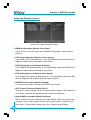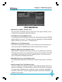
1
Statement:
This manual is the intellectual property of Foxconn Inc. Although the
information in this manual may be changed or modified at any time,
Foxconn does not obligate itself to inform the user of these changes.
Trademark:
All trademarks are the property of their respective owners.
Version:
User’s Manual V1.1 in English for NF4K8MC/NF4XK8MC series motherboard.
P/N: 91-181-NF4-KX-1E
Symbol description:
Note: refers to important information that can help you to use motherboard
better.
Attention: indicates that it may damage hardware or cause data loss,
and tells you how to avoid such problems.
Warning: means that a potential risk of property damage or physical
injury exists.
More information:
If you want more information about our products, please visit the following
website: http://www.foxconnchannel.com
NF4K8MC&NF4XK8MC-manual-English-preface.p651
2005-4-18, 15:13
Declaration of conformity
HON HAI PRECISION INDUSTRY COMPANY LTD
66 , CHUNG SHAN RD., TU-CHENG INDUSTRIAL DISTRICT,
TAIPEI HSIEN, TAIWAN, R.O.C.
declares that the product
Motherboard
NF4K8MC/NF4XK8MC
is in conformity with
(reference to the specification under which conformity is declared in
accordance with 89/336 EEC-EMC Directive)
EN 55022/A1: 2000
Limits and methods of measurements of radio disturbance
characteristics of information technology equipment
EN 61000-3-2/A14:2000 Electromagnetic compatibility (EMC)
Part 3: Limits
Section 2: Limits for harmonic current emissions
(equipment input current <= 16A per phase)
EN 61000-3-3/A1:2001
Electromagnetic compatibility (EMC)
Part 3: Limits
Section 2: Limits of voltage fluctuations and flicker in low-voltage
supply systems for equipment with rated current <= 16A
EN 55024/A1:2001
Information technology equipment-Immunity characteristics limits
and methods of measurement
Signature :
Printed Name :
Place / Date :
James Liang
NF4K8MC&NF4XK8MC-manual-English-preface.p652
Position/ Title :
TAIPEI/2005
Assistant President
2005-4-18, 15:13
Declaration of conformity
Supplementary Information:
This device complies with Part 15 of the FCC Rules. Operation is subject to the
following two conditions : (1) this device may not cause harmful interference, and (2)
this device must accept any interference received, including interference that may
cause undesired operation.
Tested to comply with FCC standards.
Signature :
NF4K8MC&NF4XK8MC-manual-English-preface.p653
Date :
2005
2005-4-18, 15:13
Table of Contents
Chapter
Product Introduction
Main Features .............................................................................................. 2
Motherboard Layout .................................................................................... 4
Chapter
Installation Instructions
CPU .............................................................................................................. 7
Memory ....................................................................................................... 11
Power Supply ............................................................................................ 13
Rear Panel Connectors .............................................................................. 14
Other Connectors ...................................................................................... 16
Expansion Slots ......................................................................................... 20
Jumpers ..................................................................................................... 22
Chapter
BIOS Description
Enter BIOS Setup .......................................................................................
Main menu .................................................................................................
Standard CMOS Features ..........................................................................
BIOS Feature .............................................................................................
26
26
28
31
Advanced BIOS Features .......................................................................... 32
Advanced Chipset Features ...................................................................... 34
Integrated Peripherals ................................................................................ 36
Power Management Setup ......................................................................... 39
PnP/PCI Configurations ............................................................................... 41
PC Health Status ........................................................................................ 42
Load Fail-Safe Defaults ............................................................................. 43
Load Optimized Defaults ............................................................................ 43
Set Supervisor/User Password ................................................................. 43
Save & Exit Setup ...................................................................................... 44
Exit Without Saving .................................................................................... 44
NF4K8MC&NF4XK8MC-manual-English-preface.p654
2005-4-18, 15:13
Table of Contents
Chapter
Driver CD Introduction
Utility CD content ........................................................................................
Start to install drivers .................................................................................
Chapter
NVIDIA RAID Introduction
NVIDIA RAID .............................................................................................
NF4K8MC&NF4XK8MC-manual-English-preface.p655
2005-4-18, 15:13
Warning:
1. Attach the CPU and heatsink using silica gel to ensure full contact.
2. It is suggested to select high-quality, certified fans in order to avoid
damage to the motherboard and CPU due to high temperature.
3. Never turn on the machine if the CPU fan is not properly installed.
4. Ensure that the DC power supply is turned off before inserting or re
moving expansion cards or other peripherals, especially when you
insert or remove a memory module. Failure to switch off the DC
power supply may result in serious damage to your system or
memory module.
Warning:
We cannot guarantee that your system will operate normally while
overclocked. Normal operation depends on the overclock capacity of
your device.
Attention:
Since BIOS programs are upgraded from time to time, the BIOS description in this manual is just for reference. We do not guarantee that
the content of this manual will remain consistent with the actual BIOS
version at any given time in the future.
Attention:
The pictures of objects used in this manual are just for your reference.
Please refer to the physical motherboard.
NF4K8MC&NF4XK8MC-manual-English-preface.p656
2005-4-18, 15:13
This manual is suitable for motherboard of NF4K8MC/
NF4XK8MC series. Each motherboard is carefully designed
for the PC user who wants diverse features.
-L
-K
with onboard 10M/100M LAN
with onboard 1Giga LAN
-6
-8
with 6-channel audio
with 8-channel audio
-E
-S
with 1394 function
with SATA function
-R
with RAID function
You can find PPID label on the motherboard. It indicates the
functions that the motherboard has.
For example:
On the blue mark of the PPID label, it means the
motherboard supports 6-channel Audio (-6), 1394 port (-E),
onboard 10M/100M LAN (-L), SATA function (-S).
NF4K8MC&NF4XK8MC-manual-English-preface.p657
2005-4-18, 15:13
Chapter
1
Thank you for buying WinFast NF4K8MC/NF4XK8MC series
motherboard. This series of motherboard is one of our new
products, and offers superior performance, reliability and
quality, at a reasonable price. This motherboard adopts the
advanced nForce 4 chipset, providing users a computer platform with a high integration-compatibility-performance price
ratio.
This chapter includes the following information:
Main Features
Motherboard Layout
Chapter 1 Product Introduction
Main Features
Size:
mATX form factor of 9.6” x 9.6”
Microprocessor:
Supports Socket-939 for AMD AthlonTM 64/AthlonTM 64 FX processors
Supports HyperTransport technology
Chipset:
NVIDIA chipset: nForce 4
System Memory
Two 184-pin DDR DIMM slots
Supports DDR 266/333/400 memory
Supports 128/256/512/1024Mb technology up to 2GB
USB 2.0 Port
Supports hot-plug
Eight USB 2.0 ports (four rear panel ports, two onboard USB headers
providing four extra ports)
Supports wake-up from S1 and S3 mode
Supports USB 2.0 protocol up to 480Mbps transmission rate
Onboard Serial ATA (optional)
150MBps transfer rate
Supports four S-ATA devices
Onboard 1394 (optional)
Supports hot-plug
With rate of transmission at 400Mbps
Self-configured addressing
Supports two independent 1394 units synchronously at most, such as HDD,
CD-ROM
2
Chapter 1 Product Introduction
Onboard LAN(-L/-K) (optional)
Supports10/100/1000(-L/-K)Mbps Ethernet
LAN interface built-in on board
Onboard Audio
AC’ 97 2.3 Specification Compliant
Supports S/PDIF output
Onboard Line-in jack, Microphone jack, Line-out jack
Supports 6-channel audio (setting via software)
BIOS
Licensed advanced AWARD (Phoenix) BIOS, supports flash ROM, Plug-andPlay
Supports HDD, Floppy, CD-ROM, SCSI HDD or USB device boot up
Green Function
Supports ACPI (Advanced Configuration and Power Interface)
Supports S0 (normal), S1 (power on suspend), S3 (suspend to RAM), S4
(suspend to disk-depends on OS), and S5 (soft-off) ACPI state
Expansion Slots
Two PCI slots
One PCI Express x1 slot
One PCI Express x16 Graphics slot
Advanced Features
PCI 2.3 Specification Compliant
Supports PC Health function (capable of monitoring system voltage, CPU/
system temperature, and fan speed)
3
Chapter 1 Product Introduction
Motherboard Layout
1.
15.COM2 Connector
2.Front Audio Connector
16.Boot Block Jumper
3.CD_IN Connector
17.SATA Connectors
4.AUX_IN Connector
18.ATA 133/100/66/33 IDE Connectors
5.SPDIF_OUT Connector
19.FDD Connector
6.Speaker Connector
20.IrDA Connector
7.PCI Expansion Slots
21.24-pin ATX Power Connector
8.Chipset Fan Connector
22.184-pin DIMM Slots
9.Chipset: NVIDIA nForce4
23.CPU_FAN Connector
10.USB2.0 Connectors
24.Socket 939
11.Chassis Intruder Connector
25.PCI Express x16 Slot
12.Front Panel Connector
26.PCI Express x1 Slot
13.BIOS Write-Protection Jumper
27.4-pin Power Connector
14.Clear CMOS Jumper
System Fan Connector
Note: The above motherboard layout is provided for reference only; please
refer to the physical motherboard.
4
Chapter 1 Product Introduction
Chapter
This chapter introduces the hardware installation process,
including the installation of the CPU and memory. It also
addresses the connection of your power supply, use of the
rear panel connectors, connection of hard drive and floppy
drive data cables, and setting up various other feature of the
motherboard. Caution should be exercised during the installation process. Please refer to the motherboard layout
prior to any installation and read the contents in this chapter
carefully.
This chapter includes the following information:
CPU
Memory
Power Supply
Rear Panel Connectors
Other Connectors
Expansion Slots
Jumpers
5
Chapter 2 Installation Instructions
Take note of the following precautions before you install components
or change settings.
1. Use a grounded wrist strap or touch a safely grounded object, such
as an attached power supply, before handling components to avoid
damaging them due to static electricity.
2. Unplug the power cord before opening your chassis or touching any
components.
3. Hold components by their edges to avoid touching any exposed
integrated circuits (ICs).
4. Whenever you uninstall a component, place it on a grounded antistatic pad or into the anti-static bag that it came in.
6
Chapter 2 Installation Instructions
This motherboard supports Athlon TM 64, Athlon TM 64FX family processors with
HyperTransport TM Technology.
Attention:
The CPU pins must be properly aligned with the holes in the
socket, otherwise the CPU may be damaged.
Installation of CPU
Follow these steps to install the CPU.
1. Unlock the socket by pressing the lever sideways, then lift it up to a 90 o
angle.
Gap in the base
2. Align the cut edge to the gap in the
base of the socket. Carefully insert the
CPU into the socket until it fits in place.
Cut edge
Push down the socket
lever to secure the CPU.
When the CPU is in place, press it
firmly on the socket while you push
down the socket lever to secure the
CPU. The lever clicks on the side tab
to indicate that it is locked.
7
Chapter 2 Installation Instructions
Installation of CPU Fan
New technology allows processors to run at higher and higher frequencies.
To avoid problems arising from high-speed operation, for example,
overheating, you need to install the proper fan. The following procedure is
provided for reference only, please refer to your CPU fan user guide for the
actual procedure.
CPU Fan
CPU Heatsink
CPU Retention
Mechanism
CPU Retention Bracket
CPU Retention Lock
1.Locate the CPU retention mechanism base (surrounds the CPU
2. If required, apply a light coating of
silica gel to the top of the CPU.
socket).
NOTE: The CPU heatsink may have
a pre-applied thermal compound. In
that case, the silica gel is not required.
8
Chapter 2 Installation Instructions
3. Place the cooling set onto the re-
4. Align the other end of the reten-
tention mechanism. Attach one end
of the retention bracket to retention
tion bracket to fasten the cooling
set on the top of the retention
mechanism.
mechanism.
5. Push down the retention bracket lock on the retention mechanism to secure
the heatsink and fan to module base.
6. Connect the fan’s power cable to the appropriate 3-pin terminal on the
motherboard.
9
Chapter 2 Installation Instructions
CPU Qualified Vendor List
The following table lists the CPUs that have been tested and qualified for use
with this motherboard.
Vendor
10
Description
AMD
Athlon 64 3500+
AMD
Athlon 64 3800+
AMD
Athlon 64 4000+
AMD
Athlon 64 FX-55
AMD
Athlon 64 FX-53
Chapter 2 Installation Instructions
Memory
This motherboard includes two 184-pin slots with 266/333/400 MHz Dual Channel DDR DRAM interface, You must install at least one memory module to
ensure normal operation and install to DIMM1 at first. If you install two modules,
they must be the same speed. Mixing memory modules from different manufactures are not recommended.
Installation of DDR Memory
1. There is only one gap in the center of the DIMM slot, and the memory module
can be fixed in one direction only.
2. Align the memory module to the DIMM slot, and insert the module vertically into the DIMM slot.
3. The plastic clips at both sides of the DIMM slot will lock automatically.
Note:
Be sure to unplug the AC power supply before adding or removing
expansion cards or other system peripherals, especially the
memory devices, otherwise your motherboard or the system
memory might be seriously damaged.
11
Chapter 2 Installation Instructions
Memory Qualified Vendor List
The following table list is the memory modules that have been tested and
qualified for use with this motherboard.
12
Vendor
Type
Size
CORSAIR
CORSAIR
CORSAIR
LPT
HLX
KINGMAX
CRL
NANYA
GEIL
TWINMOS
INFINEON
K-DATA
SAMSUNG
NANYA
SAMSUNG
SAMSUNG
INFINEON
INFINEON
MT
MT
MT
HYNIX
HYNIX
INFINEON
SAMSUNG
SAMSUNG
CORSAIR
CROTALUS
KINGSTON
APACER
APACER
KINGSTEK
KINGSTEK
NANYA
MT
DDR466
DDR500
DDR400
DDR500
DDR266
DDR266
DDR333
DDR333
DDR400
DDR400
DDR333
DDR400
DDR400
DDR266
DDR400
DDR333
DDR400
DDR333
DDR333
DDR333
DDR333
DDR333
DDR400
DDR400
DDR333
DDR333
DDR400
DDR400
DDR400
DDR333
DDR400
DDR400
DDR333
DDR333
DDR333
256MB
256MB
512MB
256MB
256MB
256MB
512MB
1GB
512MB
1GB
1GB
512MB
128MB
128MB
256MB
512MB
128MB
128MB
256MB
128MB
512MB
128MB
128MB
256MB
256MB
128MB
512MB
512MB
256MB
256MB
256MB
512MB
512MB
512MB
256MB
Chapter 2 Installation Instructions
Power Supply
This motherboard uses an ATX power supply. In order to avoid damaging any
devices, make sure that they have been installed properly prior to connecting
the power supply.
24-pin ATX Power Connector
24-pin ATX Power Connector: PWR1
PWR1 is the ATX power supply connector.
Make sure that the power supply cable
and pins are properly aligned with the
connector on the motherboard. Firmly
plug the power supply cable into the connector and make sure it is secure.
+5V
+5V
GND
+5V
PSON
RSVD GND
GND GND
GND +3.3V
-12V
13
24
12
1
GND
GND
+3.3V +12V
+12V
PWROK +5V
GND
+5V
+5V_AUX
4-pin ATX 12V Power Connector: PWR2
The 4 pin ATX 12V power supply connects
to PWR2 and provides power to the CPU.
4-pin ATX 12V Power Connector
GND
12V
GND
12V
Attention:
We strongly recommend you use 24-pin
power supply. If you want to use 20-pin
power supply, you need to align the ATX
power connector according to the right
picture.
13
Chapter 2 Installation Instructions
Rear Panel Connectors
This motherboard provides the following ports as below:
4 Parallel Port
(Printer Port)
6
1394 Port
(optional)
7
LAN Port
(optional)
Line-in jack
1 PS/2 Mouse
Connector
Line-out jack
2 PS/2 Keyboard
Connector
Microphone
jack
3 Serial Port
(COM1)
1
8
5 USB 2.0 Ports
PS/2 Mouse Connector
This green 6-pin connector is for a PS/2 mouse.
2
PS/2 Keyboard Connector
This purple 6-pin connector is for a PS/2 keyboard.
Serial Port (COM1)
This 9-pin COM1 port is for pointing devices or other serial devices.
3
Parallel Port (Printer Port)
This 25-pin port connects a parallel printer, a scanner, or other devices.
4
5
USB 2.0 Ports
These four Universal Serial Bus (USB) ports are available for connecting USB
2.0/1.1 devices.
6
1394 Port (optional)
This digital interface supports electronic devices such as digital cameras,
scanners, and printers.
7
LAN Port (optional)
This port allows connection to a Local Area Network (LAN) through a network hub.
8
Line-in jack, Line-out jack, Microphone jack
When using a two-channel sound source, the Line-out jack is used to connect
to speakers or headphones; the Line-in jack connects to an external CD player,
tape player or other audio device. The Microphone jack is used to connect to the
microphone.
14
Chapter 2 Installation Instructions
Line-in
Line-out
Microphone
When using a 6-channel sound source, connect the front speaker to the green
audio output; connect the surround sound speaker to the blue audio output;
connect the center speaker/subwoofer to the red Microphone output, as shown
in the following figure:
Blue
Green
Center
Red
Front Left
Front Right
Rear Right
Rear Left
Subwoofer
15
Chapter 2 Installation Instructions
Other Connectors
This motherboard includes connectors for FDD, IDE devices, SATA devices,
USB devices, IR module, CPU fan, system fan, and others.
Floppy Connector: FLOPPY
This motherboard includes a standard floppy connector, supporting 360 K, 720 K,
1.2 M, 1.44 M, and 2.88 M FDDs.
HDD Connector: IDE1&IDE2
These connectors support the provided UltraDMA 133/100/66/33 IDE hard disk
ribbon cable. Connect the cable’s blue connector to the primary (recommended)
or secondary IDE connector, then connect the gray connector to the UltraDMA
133/100/66/33 slave device (hard disk drive) and the black connector to the
UltraDMA 133/100/66/33 master device. If you install two hard disks, you must
configure the second drive as a slave device by setting its jumper accordingly.
Refer to the hard disk documentation for the jumper settings.
Attention:
Ribbon cables are directional, therefore, make sure to always connect with the cable on the same side as pin 1 of the PIDE/SIDE or
FLOPPY connector on the motherboard.
Front Panel Connector: JFP1
Attach the power LED, IDE LED, reset switch
and power switch connectors to the corresponding pins.
1
IDE_LED
+
-
+
-
RESET
PLED
PWRBTN#
NC
JFP1
Hard Disk LED Connector (IDELED)
Attach the connector to the IDELED on the front panel of the case; the LED will
flash while the HDD is in operation.
Reset Switch (RESET)
Attach the connector to the Reset switch on the front panel of the case; the
system will restart when the switch is pressed.
16
Chapter 2 Installation Instructions
Power LED Connector (PLED)
Attach the connector to the Power LED on the front panel of the case. The Power
LED indicates the power supply status. When the system is in S0 status, the
LED is on. When the system is in S1 status, the LED is blinking. When the
system is in S3, S4, S5 staus, the LED is off.
Power Switch Connector (PWRBTN#)
Attach the connector to the power button of the case. Pushing this switch allows
the system to be turned on and off rather than using the power supply button.
USB Connectors: F_USB 1, F_USB 2
Besides four USB ports on the rear panel, the series of motherboards also
have two 10-pin headers on board which may connect to the front panel USB
cable to provide additional four USB ports.
10
10
9
Empty
NC
9
NC
Empty
GND
GND
GND
GND
D4+
D5+
D2+
D3+
D4-
D5-
D2-
D3-
VCC
VCC
VCC
2
VCC
2
1
1
F_USB2
F_USB1
FAN Connectors: CPU_FAN1, SYS_FAN, CHIP_ FAN
Connect the CPU cooling fan cable into the 3-pin CPU_FAN1 on the motherboard.
Connect the system cooling fan cable into the 3-pin SYS_FAN on the motherboard.
Connect the chipset fan cable into the 3-pin CHIP_FAN connector on the
motherboard.
CPU_FAN1
SYS_FAN
CHIP_ FAN
IrDA Connector: JIR1
The IrDA infrared transmission allows your computer to send and receive data via an infrared ray.
The relevant parameters in the BIOS “Integrated
Peripherals” should be set prior to using this
GND Empty
1
IRTX
IRRX +5V
function.
17
Chapter 2 Installation Instructions
S-ATA Connectors: SATA0, SATA1, SATA2, SATA3 (optional)
The Serial ATA connectors are used to connect the
Serial ATA devices to the motherboard. These connectors support the thin Serial ATA cables for pri-
GND
RXTXGND
RX+
GND
TX+
mary internal storage devices. The current Serial
ATA interface allows up to 150MB/s data transfer
SATA0/1/2/3
rate.
Front Audio Connector: F_AUDIO1
The audio port includes two parts – the Front
Audio and Rear Audio. Their priority is sequenced from high to low (Front Audio to Rear
Audio). If headphones are plugged into the
front panel of the chassis (using the Front
Audio), then the Line-Out (Rear Audio) on the
rear panel will not work. If you do not want to
use the Front Audio, pin 5 and 6, pin 9 and 10
1
2
MIC_IN
MIC_GND
MIC_PWR
+5VAC
AUD_OUT_R
AUD_RET_R
NC
EMPTY
AUD_RET_L
AUD_OUT_L
9
10
F_AUDIO1
must be short, and then the signal will be
sent to the rear audio port.
CD_L
Audio Connectors: CD_IN1, AUX_IN1 (optional)
GND
CD_IN, AUX_IN are Sony standard CD audio
connectors. These connectors allow you to receive
CD_IN1
CD_R
AUX_R
stereo audio input from sound sources such as CDROM. Attach its audio connector to the CD_IN/AUX_IN
GND
audio connectors on the motherboard.
AUX_IN1
AUX_L
Speaker Connector: SPK1 (optional)
SPK (pull high)
The speaker connector is used to connect
speaker of the chassis.
Empty
NC
SPKJ
SPK
18
Chapter 2 Installation Instructions
S/PDIF Out Connector: SPDIF_O1
The S/PDIF out connector is capable of providing
3.3V
digital audio to external speaker or compressed
AC3 data to an external Dolby digital decoder.
SPDIF OUT
GND
SPDIF_O1
COM2 Connector: COM2 (optional)
This connector accommodates a second serial port
RI
RTS SOUT
GND RLSD
using an optional serial port bracket. Connect the
bracket cable to this connector, then install the
bracket into a slot opening at the back of the system
chassis.
Empty DSR SIN
CTS DTR
COM2
Chassis Intruder Connector: INTRUDER (optional)
The connector connects to the chassis security
switch on the case. The system can detect the chassis intrusion through the status of this connector. If
the connector has been closed once, the system
will send a message. To utilize this function, set
the “Intruder# Detection” in the “Power Management
Setup” section of the CMOS Setup.Save and exit,
then boot the operating system once to make sure
this function takes effect.
INTRUDERJ
GND
INTRUDER
1394 Connector: F_1394 (optional)
The 1394 expansion cable can be connected to
either the front (provided that the front panel of your
chassis is equipped with the appropriate interface)
or the rear panel of the chassis.
10
9
GND
+12V
+12V
TPB-
TPB+
GND
GND
TPA-
TPA+
2
1
F_1394
19
Chapter 2 Installation Instructions
Expansion Slots
This motherboard includes two 32-bit Master PCI bus slots and one PCI Express x1 slot, and one PCI Express x16 slot.
PCI Slots
The expansion cards can be installed in the two PCI slots. When you install or
remove such cards, please make sure that the power cord has been unplugged
from the power supply. Please read carefully the instructions provided for such
cards, then install and set the necessary hardware and software for such cards,
such as the jumper or BIOS settings.
PCI Express Slots
PCI Express will offer the following design advantages over the PCI and AGP
interface:
-Compatible with existing PCI drivers and software and Operating Systems.
-High Bandwidth per Pin. Low overhead. Low latency.
-PCI Express supports a raw bit-rate of 2.5Gb/s on the data pins. This results in a real bandwidth per pair of 250MB/s.
-A point to point connection, allows each device to have a dedicated connection without sharing bandwidth.
-Ability to comprehend different data structure.
-Low power consumption and power management features.
PCI Express will take two forms, x16 and x1 PCI Express slots. Whereas the x16
slot is reserved for graphic/video cards, the x1 slots are designed to accommodate less bandwidth-intensive cards, such as a modem or LAN card.
The difference in bandwidth between the x16 and x1 slots are notable to be
sure, with the x16 slot pushing 4 GB/sec (8 GB/sec concurrent) of bandwidth,
and the x1 PCI Express slot offering 250 MB/sec.
Warning:
If a performance graphics card was installed to 16x PCI Express slot, 2x12 pin power supply was strongly recommended,
since that card maybe drawn 75W power.
20
Chapter 2 Installation Instructions
Installing an expansion card
1. Before installing the expansion card, read the documentation that came with
it and make the necessary hardware settings for the card.
2. Make sure to unplug the power cord before adding or removing expansion
cards.
3. Align the card connector with the slot and press firmly until the card is
completely seated on the slot.
4. Secure the card to the chassis with the screw you removed earlier.
PCI Express x16 Graphics Cards Qualified Vendor List
The following table lists the PCI Express x16 graphics cards that have been
tested and qualified for use with this motherboard.
Vendor
Type
Video Memory
WINFAST
ATI
NVIDAI GEFORCE X6600
REDION X300 SE
128MB
128MB
NVIDIA
NVIDIA
GEFORCEX 5750
GeForce PCX 5300
128MB
128MB
ASUS
ASUS
GeForce PCX 5300
GeForce En5900
128MB
128MB
ASUS
ASUS
AX600XT-TD
Radeon X600SE
128MB
128MB
21
Chapter 2 Installation Instructions
Jumpers
Users can change the jumper settings on this motherboard if necessary. This
section explains how to use the various functions of this motherboard by changing the jumper settings. Users should read the following contents carefully prior
to modifying any jumper settings.
Description of Jumpers
For the jumpers on this motherboard, pin 1 can be identified by the silkscreen printed
next to it. However, in this manual, pin 1 is simply labeled
as “1”.
The following table provides some explanations of the jumper pin settings.
Users should refer to the table while adjusting jumper settings.
Jumper
Diagram
Definition
Description
Set pin 1 and pin 2 closed
Set pin 2 and pin 3 closed
Closed
Set the pin closed
Open
Set the pin opened
Clear CMOS Jumper: JCMS1
This motherboard uses the CMOS RAM to store all
the set parameters. The CMOS can be cleared by
1
removing the CMOS jumper.
Normal
(Default)
1. Turn off the AC power supply and short pins 1 and
2 on the jumper.
2. Return the jumper to the normal setting (locking
pins 2 and 3 together with the jumper cap).
1
Clear
JCMS1
3. Turn on the system. The BIOS is returned to the
default settings.
Warning:
1. Disconnect the power cable before adjusting the jumper
settings.
2. DO NOT clear the CMOS while the system is turned on.
22
Chapter 2 Installation Instructions
BIOS Writer-Protection Jumper: JWP1
If the jumper JWP1 is set as enable (pin 2 & pin 3),
the system BIOS is protected from being attacked
by a serious virus, such as the CIH virus. You will
be unable to flash the BIOS to the motherboard
when the system BIOS is protected.
1
EN WP
1
Normal
(Default)
JWP1
BIOS Boot Block Jumper: JBB1
The system cannot boot if the BIOS fails to be
flashed in conventional flash BIOS process. You
will no such worry when you use the BIOS boot
block jumper. It is used to protect BIOS ”Top Boot
Block”. The system still can boot by using this function and show some information to recover the BIOS
even if flash BIOS fail. To utilize this function, you
1
Enable
1
Normal
JBB1
just set this jumper as enable (pin 1 & pin 2).
23
Chapter 2 Installation Instructions
Starting up for the first time
1. After making all the connections, replace the system case cover.
2. Make sure that all switches are turned off.
3. Turn on the devices in the following order.
a. Monitor
b.
c.
External SCSI devices (starting with the last device on the chain)
System power
4. After powering on, LED on the system front panel case lights up. For ATX
power supplies, the system LED lights up when you press the ATX power
switch. If your monitor complies with green standards or if it has a power
standby feature, the monitor LED may light up or switch between orange and
green after the system LED turns on. The system then enters the Power-On
Self Test (POST) routines. While the tests are running, the BIOS beeps or
additional messages appear on the screen. If you do not see anything within
30 seconds from the time you turned on the power, the system may have
failed a power-on test. Check the jumper settings and connections or call
your retailer for assistance.
5. After the POST routines are completed, press the <Del> key to access the
BIOS Setup Utility. For detailed instructions, please refer to Chapter 3.
Powering off the computer
1. Using the OS shut down function
If you use windows 98/ME/2000/XP, click Start and select Shut Down, then
click the OK button to shut down the computer. The power supply should
turn off after Windows shuts down.
2. Using the dual function power switch
While the system is ON, pressing the power switch for less than 4 seconds puts the system in sleep mode or soft-off mode, depending on the
BIOS setting. Pressing the power switch for more than 4 seconds lets the
system enter the soft-off mode regardless of the BIOS setting.
24
Chapter
This chapter tells how to change system settings through the
BIOS Setup menus. Detailed descriptions of the BIOS parameters are also provided.
You have to run the Setup Program when the following cases
occur:
1. An error message appears on the screen during the
system POST process.
2. You want to change the default CMOS settings.
This chapter includes the following information:
Enter BIOS Setup
Main Menu
Standard CMOS Features
BIOS Feature
Advanced BIOS Features
Advanced Chipset Features
Integrated Peripherals
Power Management Setup
PnP/PCI Configurations
PC Health Status
Load Fail-Safe Defaults
Load Optimized Defaults
Set Supervisor/User Password
Save & Exit Setup
Exit Without Saving
Chapter 3 BIOS Description
Enter BIOS Setup
The BIOS is the communication bridge between hardware and software,
correctly setting up the BIOS parameters is critical to maintain optimal system
performance. Power on the computer, when the following message briefly
appears at the bottom of the screen during the POST (Power On Self Test),
press the <Del> key to enter the Award BIOS CMOS Setup Utility.
Press TAB to show POST screen, DEL to enter SETUP.
Note:
We do not suggest that you change the default parameters in the
BIOS Setup, and we shall not be responsible for any damage that
results from any changes that you make.
Main Menu
The main menu allows you to select from the list of setup functions and two exit
choices. Use the arrow keys to select among the items and press <Enter> to
accept or go to the sub-menu.
The items in the BIOS Setup main menu are explained below:
Standard CMOS Features
The basic system configuration can be set up through this menu.
BIOS Feature
The general system feature can be set up through this menu.
26
Chapter 3 BIOS Description
Advanced BIOS Features
The advanced system features can be set up through this menu.
Advanced Chipset Features
The values for the chipset can be changed through this menu, and the system performance can be optimized.
Integrated Peripherals
All onboard peripherals can be set up through this menu.
Power Management Setup
All the items of Green function features can be set up through this menu.
PnP/PCI Configurations
The system’s PnP/PCI settings and parameters can be modified through
this menu.
PC Health Status
This will display the current status of your PC.
Load Fail-Safe Defaults
The default BIOS settings can be loaded through this menu.
Load Optimized Defaults
The optimal performance settings can be loaded through this menu,
however, the stable default values may be affected.
Set Supervisor/User Password
The supervisor/user password can be set up through this menu.
Save & Exit Setup
Save CMOS value settings to CMOS and exit setup.
Exit Without Saving
Abandon all CMOS value changes and exit setup.
27
Chapter 3 BIOS Description
Standard CMOS Features
This sub-menu is used to set up the standard CMOS features, such as the
date, time, HDD model and so on. Use the arrow keys select the item to set
up, and then use the <PgUp> or <PgDn> key to choose the setting values.
Standard CMOS Features Menu
Date
This option allows you to set the desired date (usually as the current date) with
the <day><month><date><year> format.
day
month
date
year
weekday from Sun. to Sat., defined by BIOS (read-only).
month from Jan. to Dec.
date from 1st to 31st, can be changed by using the keyboard.
year, set up by users.
Time
This option allows you to set up the desired time (usually as the current time)
with <hour><minute><second> format.
IDE Channel 0/1 Master/Slave & IDE Channel 2/3/4/5 Master
These categories identify the HDD types of 6 IDE channels installed in the
computer system. There are three choices provided for the Enhanced IDE BIOS:
None, Auto, and Manual. “None” means no HDD device is installed or set; “Auto”
indicates the system can automatically detect and configure the hard disk when
booting up; If it fails to find a device, choose “Manual” and change Access Mode
to “CHS”, then manually configure the drive by entering the characteristics of the
drive directly from the keyboard and pressing < Enter>:
Cylinder number of cylinders
Head
Precomp write pre-compensation Landing Zone
Sector
28
number of sectors
number of heads
Landing Zone
Chapter 3 BIOS Description
Award (Phoenix) BIOS can support 4 HDD modes: CHS, LBA and Large or
Auto mode.
CHS
For HDD<528MB
LBA
For HDD>528MB & supporting LBA (Logical Block Addressing)
Large
For HDD>528MB but not supporting LBA
Auto
Recommended mode
Drive A/B (optional)
This option allows you to select the kind of FDD to be installed, including
[None], [360K, 5.25in], [1.2M, 5.25in], [720K, 3.5in], [1.44M, 3.5in] and [2.88
M, 3.5in].
Video
The following table is provided for your reference in setting the display mode for
your system.
EGA/ VGA
CGA 40
CGA 80
MONO
Enhanced Graphics Adapter / Video Graphic Array. For EGA,
VGA, SEGA, SVGA, or PGA monitor adapters.
Color Graphic Adapter, powering up in 40 column mode.
Color Graphic Adapter, powering up in 80 column mode.
Monochrome adapter, including high resolution monochrome
adapters.
Halt On
This category determines whether or not the computer will stop if an error is
detected during powering up.
All Errors
No Errors
All, But Keyboard
All, But Diskette
All, But Disk/Key
Whenever the BIOS detects a nonfatal error, the
system will stop and you will be prompted.
The system boot will not stop for any errors that may
be detected.
The system boot will not stop for a keyboard error;
but it will stop for all other errors.
The system boot will not stop for a diskette error; but
it will stop for all other errors.
The system boot will not stop for a keyboard or a
disk error, but it will stop for all other errors.
29
Chapter 3 BIOS Description
Memory
This is a Displays-Only Category, determined by POST (Power On Self Test)
of the BIOS.
Base Memory
Extended Memory
Total Memory
30
The BIOS POST will determine the amount of base
(or conventional) memory installed in the system.
The BIOS determines how much extended
memory is present during the POST.
Total memory of the system.
Chapter 3 BIOS Description
BIOS Feature
BIOS Feature Menu
[SuperBoot] SuperBoot (Default: Disabled)
SuperBoot allows system-relevant information to be stored in CMOS upon
the first normal start-up of your PC, and the relevant parameters will be
restored to help the system start up more quickly on each subsequent start-up.
The available setting values are: Disabled and Enabled.
[SuperBIOS-Protect] SuperBIOS-Protect (Default: Disabled)
SuperBIOS-Protect function protects your PC from being affected by viruses,
e.g. CIH. The available setting values are: Disabled and Enabled.
[SuperRecovery] SuperRecovery Hotkey (Default: LSHIFT+F12)
SuperRecovery provides the users with an excellent data protection and HDD
recovery function. There are 12 optional hotkeys and the default hotkey is
LSHIFT+F12.
[SuperSpeed]
PCIE Clock (Depending on the specification of the PCIE)
It is used to set PCI express clock.
CPU Frequency (Depending on the specification of the CPU)
The conventional overclock method uses the jumpers on the motherboard,
and it is both troublesome and apt to errors. By using SuperSpeed, a CPU
can be overclocked by keying in the desired in the CPU frequency range.
Warning:Make sure your selection is right. Overclocking CPU/PCI Express
can adversely affect the reliability of the system and introduce errors into
your system. We will not be responsible for any damages caused.
31
Chapter 3 BIOS Description
Advanced BIOS Features
Advanced BIOS Features Menu
Removable Device Priority
This option is used to select the priority for removable device start-up. After
pressing <Enter>, you can select the removable device using the <PageUp>/
<PageDn> or Up/Down arrow keys, and change the removable device priority
using <+> or <->. To exit this option, press <Esc>.
Hard Disk Boot Priority
This option is used to select the priority for HDD start-up. After pressing
<Enter>, you can select the HDD using the <PageUp>/<PageDn> or Up/Down
arrow keys, and change the HDD priority using <+> or <->. To exit this option,
press <Esc>.
CDROM Boot Priority
This option is used to select the priority for CDROM start-up. After pressing
<Enter>, you can select the CDROM using the <PageUp>/<PageDn> or Up/
Down arrow keys, and change the CDROM priority using <+> or <->. To exit
this option, press <Esc>.
CPU Internal Cache (Default: Enabled)
This item is used to turn on or off the CPU internal cache. Leave this item
at the default value for better performance.
First/Second/Third Boot Device (Default: Removable/Hard Disk/CDROM)
This option allows you to set the boot device sequence. The available setting
values are: Removable, Hard Disk, CDROM, Legacy LAN, NVIDIA Boot Age
and Disabled.
32
Chapter 3 BIOS Description
Boot Other Device (Default: Enabled)
With this function set to Enabled, the system will boot from some other
devices if the first/second/third boot devices failed. The available setting values are: Disabled and Enabled.
Security Option (Default: Setup)
When it is set to Setup, a password is required to enter the CMOS Setup
screen; when it is set to System, a password is required not only to enter
CMOS Setup, but also to start up your PC.
33
Chapter 3 BIOS Description
Advanced Chipset Features
Advanced Chipset Features Menu
DRAM Configuration (Default: Press Enter)
Press <Enter> to set the items about DRAM Configuration. Please refer to
page 35.
CPU Spread Spectrum (Default: Center Spread)
If you enable CPU spread spectrum, it can significantly reduce the EMI (ElectroMagnetic Interference) generated by the system.
SATA Spread Spectrum (Default: Disabled)
If you enable SATA spread spectrum, it can significantly reduce the EMI (ElectroMagnetic Interference) generated by the system.
PCIE Spread Spectrum (Default: Down Speed)
If you enable PCI express spread spectrum, it can significantly reduce the EMI
(Electro-Magnetic Interference) generated by the system.
SSE/SSE2 Instructions (Default: Enabled)
It is used to set enable or disable SSE/SSE2 instructions.
CPU Thermal-Throttling (Default: 50.0%)
This item is used to specify the CPU speed (at percentage) to slow down the
CPU when it reaches the predetermined overheat temperature.
System BIOS Cacheable (Default: Disabled)
Select “Enabled” to allow caching of the system BIOS which may improve performance. If any other program writes to this memory area, a system error
may result. The available setting values are: Disabled and Enabled.
34
Chapter 3 BIOS Description
Max Memclock (MHz) (Default: Auto)
User can place an artificial memory clock limit on the system. Memory is prevented from running faster than this frequency.
1T/2T Memory Timing (Default: Auto)
This setting controls the SDRAM command rate. Selecting [Auto] allows SDRAM
signal controller to run at 1T (T=clock cycles) rate. Selecting [1T] makes SDRAM
signal controller run at 2T rate. 1T is faster than 2T.
CAS# latency (Tcl) (Default: Auto)
This option controls the CAS latency, which determines the timing delay (in
clock cycles) before SDRAM starts a read command after receiving it.
RAS# to CAS# delay (Trcd) (Default: Auto)
When DRAM is refreshed, both rows and columns are addressed separately.
This setup item allows you to determine the timing of the transition from RAS
(row address strobe) to CAS (column address strobe). The less the clock
cycles, the faster the DRAM performance.
Min RAS# active time (Tras) (Default: Auto)
This setting determines the time RAS takes to read from and write to a memory
cell.
Row Precharge Time (Trp) (Default: Auto)
This item controls the number of cycles for Row Address Strobe (RAS) to be
allowed to precharge. If insufficient time is allowed for the RAS to accumulate
its charge before DRAM refresh, refreshing may be incomplete and DRAM
may fail to retain data. This item applies only when synchronous DRAM is
installed in the system.
35
Chapter 3 BIOS Description
Integrated Peripherals
Integrated Peripherals Menu
IDE Function Setup
Press <Enter> to set the items about IDE function. Please refer to page 37.
RAID Config
Press <Enter> to set the items of RAID configuration function. Please refer to
page 38.
OnChip USB (Default: V1.1+V2.0)
This option is used to enable or disable the onboard USB controller. Selecting V1.1+V2.0 enables the system to support both USB 1.1 and USB 2.0
specification. The available setting are: Disabled, V1.1+V2.0, V1.1.
USB Keyboard Support (Default: Enabled)
This option is used to enable or disable USB keyboard under legacy OS.
AC97 Audio (Default: Auto)
This option is used to set whether onboard AC97 Audio is enabled. Disabled the controller if you want to use other controller cards to connect an
audio device.
MAC Lan (Default: Auto)
Setting to “Auto” allows the BIOS to auto-detect the NVIDIA LAN controller
and enable it. The setting options include Auto and Disabled.
36
Chapter 3 BIOS Description
IDE Function Setup Menu
Primary/Secondary Master/Slave PIO (Default: Auto)
The four IDE PIO (Programmed Input/Output) fields let you set a PIO mode
(0-4) for each of the four IDE devices that the onboard IDE interface supports.
Modes 0 through 4 provide successively increased performance. Choose
“Auto” to let the system auto detect which PIO mode is best, or select a PIO
mode from 0-4.
Primary//Secondary Master/Slave UDMA (Default: Auto)
UItraDMA technology provides faster access to IDE devices. If you install a
device that supports UItraDMA, change the appropriate items on this list to
Auto. The available setting values are: Disabled and Auto.
IDE DMA transfer access (Default: Enabled)
This option is used to enable or disable IDE DMA transfer access.
Serial-ATA 1/2 (Default: Enabled)
This option is used to enable or disable Serial-ATA 1/2.
IDE Prefetch Mode (Default: Enabled)
This option is used to enable or disable IDE Prefetch Mode.
IDE HDD Block Mode (Default: Enabled)
This option is used to set whether the IDE HDD Block Mode is allowed. The
available setting values are: Disabled and Enabled.
37
Chapter 3 BIOS Description
RAID Config Menu
RAID Enable (Default: Disabled)
This option is used to disable or enable the RAID function. When enabled,
the following grayed items will be activated.
IDE Primary/Secondary Master/Slave RAID (Default: Disabled)
This feature allows users to enable or disable the RAID function for each
IDE hard disk drive. The setting values are Enabled and Disabled.
SATA 1/2 Primary/Secondary RAID (Default: Disabled)
This feature allows users to enable or disable the RAID function for each
SATA hard disk drive. The setting values are Enabled and Disabled.
38
Chapter 3 BIOS Description
Power Management Setup
Power Management Setup Menu
ACPI function (Default: Enabled)
ACPI stands for “Advanced Configuration and Power Interface”. ACPI is a
standard that defines power and configuration management interfaces between an operating system and the BIOS. In other words, it is a standard that
describes how computer components work together to manage system
hardware. In order to use this function the ACPI specification must be supported by the OS (for example, Windows2000 or WindowsXP). The available
setting values are: Enabled and Disabled.
ACPI Suspend Type (Default: S1(POS))
This option is used to set the energy saving mode of the ACPI function.
When you select “S1 (POS)” mode, the power will not shut off and the
supply status will remain as it is, in S1 mode the computer can be resumed
at any time. When you select “S3 (STR)” mode, the power will be cut off after
a delay period. The status of the computer before it enters STR will be saved
in memory, and the computer can quickly return to the previous status when
the STR function wakes. When you select “S1 & S3” mode, the system
will automatically select the delay time.
Soft-Off by Power Button (Default: Instant-Off)
This option is used to set the power down method. This function is only valid
for systems using an ATX power supply. When “Instant-Off” is selected, press
the power switch to immediately turn off power. When “Delay 4 Sec.” is
selected, press and hold the power button for four seconds to turn off power.
WOL (PME#) From Soft-Off (Default: Disabled)
When set to Enabled, the feature allows your system to be awakened from the
power saving modes through any event on PME (Power Management Event).
39
Chapter 3 BIOS Description
WOR (RI#) From Soft-Off (Default: Disabled)
If this option is enabled, it allows the system to resume from a software power
down or power saving mode whenever there is an incoming call to an installed fax/modem. This function needs to be supported by the relevant hardware and software.
Cool N’Quiet
This feature is especially designed for AMD Athlon processor, which
provides a CPU temperature detecting function to prevent your CPU’s from
overheating due to the heavy working loading. The setting options include
Disabled and Enabled.
Power-On by Alarm (Default: Disabled)
This option is used to start up your PC by alarm. When this option is enabled,
the following two items are activated and user can set the desired alarm date
and time. The setting values are Disabled and Enabled.
Date of Month Alarm
This option is used to set the timing for the start-up date. The setting values
contain 0-31.
Time (hh:mm:ss) Alarm
This option is used to set the timing for the start-up time. The setting values
contain hh:0 – 23; mm:0 – 59; ss:0 – 59.
Power Management (Default: User Define)
This option is used to set the power management scheme. Available settings
are: User Define, Min Saving and Max Saving.
Video Off Method (Default: V/H SYNC + Blank)
This option is used to define the video off method. “Blank Screen” mode
means that after the computer enters power saving mode, only the monitor
will close, however, the vertical and horizontal scanning movement of the screen
continues. When you select the “V/H SYNC + Blank” mode the vertical and horizontal
scanning movement of screen stops when the computer enters power saving
mode. “DPMS Support” mode is a new screen power management system,
and it needs to be supported by the monitor you’re using.
HDD Power Down (Default: Disabled)
This option is used to turn off hard disk power if the hard disk is idle for a given
period of time. The setting values are Disabled and 1Min-15Min.
40
HDD Down In Suspend (Default: Enabled)
This option is used to define the continuous HDD idle time before the HDD
enters power saving mode. The setting values are Disabled and Enabled.
Chapter 3 BIOS Description
PnP/PCI Configurations
PnP/PCI Configurations Menu
Init Display First (Default: PCI Slot)
This option is used to set which display device will be used first when your PC
starts up. The available setting values are: PCI Slot, PCIEx.
Reset Configuration Data (Default: Disabled)
This option is used to set whether the system is permitted to automatically
distribute IRQ DMA and I/O addresses each time the machine is turned on.
The setting values are: Disabled and Enabled.
Resources Controlled By (Default: Auto (ESCD))
This option is used to define the system resource control scheme. If all cards
you use support PnP, then select “Auto (ESCD)” and the BIOS will automatically distribute interruption resources. If the ISA cards you installed do not
support PnP, you will need to select “Manual” and manually adjust interruption resources in the event of hardware conflicts. However, since this
motherboard has no ISA slot, this option does not apply.
IRQ Resources
Press the <Enter> key, then manually set IRQ resources.
PCI/VGA Palette Snoop (Default: Disabled)
If you use a non-standard VGA card, use this option to solve graphic acceleration card or MPEG audio card problems (e.g., colors not accurately displayed).
The setting values are: Disabled and Enabled.
Maximum Payload Size (Default:4096 )
Set maximum TLP payload size for the PCI express devices. The unit is byte.
41
Chapter 3 BIOS Description
PC Health Status
Shutdown Temperature (Default: 90oC/194oF)
This option is used to set the system temperature upper limit. When the
temperature exceeds the setting value, the motherboard will automatically
cut off power to the computer. The available setting values are: 80oC/176oF,
85oC/185oF, 90oC/194oF and 95oC/205oF.
42
Chapter 3 BIOS Description
Load Fail-Safe Defaults
Select this option and press <Enter>, it will pop up a dialogue box to allow you
to install fail-safe defaults for all appropriate items in the Setup Utility. Select
<Y> and press <Enter> to load the defaults. Select <N> and press <Enter> to not
load. The defaults set by BIOS have set the basic functions of system in order to
ensure the stability of system. But if your computer fails to properly work, you
may load the default to make the system recover normal, then carry out failure
testing in next step. If you only want to load the default for a specific option, you
can select this option and press the <F6> key.
Load Optimized Defaults
Select this option and press <Enter>, it will open a dialogue box that lets you
install the optimized defaults for all appropriate items in the Setup Utility. Select
<Y> and press <Enter> to load the optimized defaults. Select <N> and press
<Enter> to not install. The defaults set by BIOS have set the optimized performance parameters of system to improve the performances of system
components. But if the optimized performance parameters to be set cannot be
supported by your hardware devices, you can cause fatal errors or instability. If
you only want to load the optimized defaults for a specific option, you can select
this option and press the <F7> key.
Set Supervisor/User Password
The preferential grade of supervisor password is higher than user password.
You can use supervisor password to start into system or enter into CMOS setting program to amend setting. You can also use user password to start into
system, or enter into CMOS setting menu to check, but if you have set supervisor
password, you cannot amend the setting.
Highlight the item Set Supervisor / User Password on the main menu and press
<Enter>. The following password dialog box appears:
Enter Password:
Enter your password, not exceeding 8 characters, then press <Enter>, you will
be prompted to confirm the password, type in the password again and press
<Enter>.
If you are deleting a password that is already installed, just press <Enter> when
the password dialog box appears, and the screen will show a message that
indicates this password has been disabled. In this case, you can freely enter
into system and CMOS setting program.
PASS WORD DISABLED!!!
Press any key to continue...
43
Chapter 3 BIOS Description
Under the menu “Advanced BIOS Features Setup”, if you select “System” in
Security Option, the screen will prompt you to enter password once the system
is started or you want to enter CMOS setting program. If the password is wrong,
it will refuse you to continue.
Under the menu “Advanced BIOS Features Setup”, if you select “Setup” in Security Option, the screen will prompt you to enter password only when you enter
CMOS setting program.
Save & Exit Setup
Select this option and press <Enter>, the following message will appear on the
screen:
SAVE to CMOS and EXIT (Y/N)?
Press <Y> to save the changes that you have made in the Setup Utility and exit
the Setup Utility; press <N>/<ESC> to return to the main menu.
Exit Without Saving
Select this option and press <Enter>, it will show the following message on the
screen:
Quit Without Saving (Y/N)?
Press <Y> to discard any changes that you have made in the Setup Utility and
exit the Setup Utility; press <N>/<ESC> to return to the main menu.
44
Chapter
The utility CD that came with the motherboard contains useful
software and several utility drivers that enhance the motherboard features.
This chapter includes the following information:
Utility CD content
Start to install drivers
Chapter 4
Utility CD content
This motherboard comes with one Utility CD. To begin using the CD, simply insert
the CD into your CD-ROM driver. The CD will automatically display the main menu
screen.
Chapter 4
Select <Install Driver> to enter the driver installation menu (as following picture).
Click the relevant button to install nVIDIA nForce Chipset System, DirectX 9.0b.
Chapter 5 NVIDIA RAID Introduction
Chapter
5
NVIDIA brings Redundant Array of Independent Disks
(RAID) technology—which is used by the world’s leading
businesses—to the common PC desktop. This technology uses multiple drivers to either increase total disk
space or to offer data protection.
This chapter includes the following information:
Basic Configuration
Setting up BIOS
Entering the RAID BIOS Setup
NVIDIA RAID Utility Installation
Initializing and Using the Disk Array
Win2K Limitation with Bootable RAID
48
Chapter 5 NVIDIA RAID Introduction
NVIDIA RAID
RAID Arrays
This section describes the following types of RAID arrays that NVIDIA RAID
supports:
• RAID 0
RAID 0 defines a disk striping scheme that improves the disk read and write
times for many applications.
• RAID 1
RAID 1 defines techniques for mirroring data.
• RAID 0+1
RAID 0+1 combines the techniques used in RAID 0 and RAID 1 arrays.
• Spanning (JBOD)
JBOD provides a method for combining drives of different sizes into one large
disk.
Summary of RAID Configurations
Array
Advantages
RAID 0 High data throughput.
RAID 1
100% data
redundancy.
Optimized for both 100%
RAID data redundancy and
0+1 performance. Allows
spare disks.
Drawbacks
# Hard Disks Fault Tolerance
No fault tolerance.
multiple
None
Requires two drives
for the storage space
of one drive.
2
Yes
Requires two drives for
the storage space of
one drive—the same
as RAID level 1.
4+
Yes
multiple
No
Decreases perforCombines and uses the mance because of the
capacity of odd size difficulty in using drives
JBOD
concurrently or to optidrives.
mize drives for different uses.
49
Chapter 5 NVIDIA RAID Introduction
Basic Configuration Instructions
The following are the basic steps for configuring NVIDIA RAID:
Non-Bootable RAID Array
1. Choose the hard disks that are to be RAID enabled in the system BIOS.
2. Specify the RAID level, either Mirroring (RAID 1), Striping (RAID 0), Stripe
Mirroring (RAID 0+1), or Spanning (JBOD) and create the desired RAID array.
3. Install the operating system on one hard disk, then reboot the computer.
4. Run the Windows nForce Setup application and install the RAID driver.
5. Initialize the NVRAID Array.
Bootable RAID Array
1. Choose the hard disks that are to be RAID enabled in the system BIOS.
2. Specify the RAID level, either Mirroring (RAID 1), Striping (RAID 0), Stripe
Mirroring (RAID 0+1), or Spanning (JBOD) and create the desired RAID array.
3. Boot from the Windows CD, then press F6 when the Windows Setup appears.
4. Insert the RAID driver floppy to install the nForce RAID driver.
5. Initialize the NVRAID Array.
50
Chapter 5 NVIDIA RAID Introduction
Setting Up the BIOS
1. Start up the computer, then press <Delete> to enter the BIOS setup. Use the
arrow keys to select Integrated Peripherals, then press <Enter>.
2. Use the arrow keys to highlight the RAID Config, then press <Enter>.
3. From the RAID Config window, enable the RAID Enable, the other items will be
activated, then you can enable the disks that you want to use as RAID disks.
Note: Make sure to enable the SATA drives if you are setting up a RAID 0+1
array.
4. Press <F10> to save the configuration and exit.
51
Chapter 5 NVIDIA RAID Introduction
Entering the RAID BIOS Setup
1. After rebooting your PC, wait until you see the RAID software prompting you to
press <F10>. The RAID prompt appears as part of the system POST and boot
process prior to loading OS.
2. Press <F10>, and the NVIDIA RAID Utility --- Define a New Array window will
appear.
By default, RAID Mode is set to Mirroring and Striping Block is set to Optimal.
Understanding the “Define a New Array” Window
Use the Define a New Array window to
• Select the RAID Mode
• Set up the Striping Block
• Specify which disks to use for the RAID Array
Depending on the platform used, the system can have one or more channels. In
a typical system there is usually one adapter and multiple channels, and each
channel has a slave and a master.
The adapter/channel/master/slave status of each hard disk is given in the Loc
(location) columns of the Free Disks and Array Disks lists.
1.0.M
M: Master
S: Slave
0: Channel
Adapter - Typically, adapter 0 is used for
52
Parallel ATA drivers while adapter 1 and
above is used for Serial ATA drives.
Chapter 5 NVIDIA RAID Introduction
In the example above, 1.0.M means the hard drive is attached to Adapter 1,
Channel 0, and the drive is set to Master. The following is a list of all possible
combinations:
Parallel ATA
0.0.M
0.0.S
Adapter 0, Channel 0, Master
Adapter 0, Channel 0, Slave
0.1.M
0.1.S
Adapter 0, Channel 1, Master
Adapter 0, Channel 1, Slave
Serial ATA
1.0.M
Adapter 1, Channel 0, Master
1.1.M
2.0.M
Adapter 1, Channel 1, Master
Adapter 2, Channel 0, Master
2.1.M
Adapter 2, Channel 1, Master
Note: There is no such thing as Slave drive in Serial ATA. All drives are considered to be Master since there is a one to one connection between the drive and
the controller.
Using the Define a New Array Window
If necessary, press the <Tab> key to move from field to field until the appropriate
field is highlighted.
• Selecting the RAID Mode
By default, this is set to [Mirroring]. To change to a different RAID mode, press
the down arrow key until the mode that you want appears in the RAID Mode
box—either [Mirroring], [Striping], [Spanning], or [Stripe Mirroring].
• Selecting the Striping Block Size
Striping Block size is given in kilobytes, and affects how data is arranged on the
disk. It is recommended to leave this value at the default [Optimal], which is
32KB, but the values can be between [4 KB] and [128 KB].
• Assigning the Disks
The disks that you enabled from the RAID Config BIOS setup page appear in the
Free Disks block. These are the drives that are available for use as RAID array
disks.
53
Chapter 5 NVIDIA RAID Introduction
To designate a free disk to be used as a RAID array disk,
1. Tab to the Free Disks section. The first disk in the list is selected.
2. Move it from the Free Disks block to the Array Disks block by pressing the right
arrow key ( ). The first disk in the list is moved, and the next disk in the list is
selected and ready to be moved.
3. Continue pressing the right-arrow key (
) until all the disks that you want to
use as RAID array disks appear in the Array Disks block.
It shows that two disks have been assigned as RAID1 array disks in the figure
above.
Completing the RAID BIOS Setup
1. After assigning your RAID array disks, press <F7>. The Clear disk data prompt
appears.
54
Chapter 5 NVIDIA RAID Introduction
2. Press <Y> if you want to wipe out all the data from the RAID array, otherwise
press <N>. You must choose Yes if the drives were previously used as RAID
drives.
The Array List window appears, where you can review the RAID arrays that you
have set up.
3. Use the arrow keys to select the array that you want to set up, then press
<Enter>. The Array Detail window appears.
4. If you want to mark this disk as empty and wipe out all its contents then press
<C>.
5. At the prompt, press <Y> to wipe out all the data, otherwise press <N>.
6. Press <Enter> again to return to the previous window and then press <Ctrl>
+ <X> to exit the RAID setup.
55
Chapter 5 NVIDIA RAID Introduction
NVIDIA RAID Utility Installation
Installing the NVIDIA RAID Software Under Windows (for Non-bootable RAID
Array)
This section describes how to run the setup application and install the RAID
software which will upgrade the Windows IDE driver and install the RAID driver.
1. Start the nForce Setup program to open the NVIDIA Windows nForce Drivers
page.
2. Select the modules that you want to install. Select the relative options that you
have configured.
3. Click Next and then follow the on-screen instructions.
4. After the installation is completed, be sure to reboot the PC.
5. After the reboot, initialize the newly created array.
56
Chapter 5 NVIDIA RAID Introduction
Installing the RAID Driver (for bootable RAID Array)
1. After you complete the RAID BIOS setup, boot from the Windows CD, and the
Windows Setup program starts.
2. Press <F6> and wait for the Windows Setup screen to appear.
3. Specify the NVIDIA drivers:
(1) Insert the floppy that has the RAID driver, press <S>, then press <Enter>. The
Windows Setup screen appears as below:
(2) Select “NVIDIA RAID CLASS DRIVER (required)” and then press <Enter>.
(3) Press <S> again at the Specify Devices screen, then press <Enter>.
(4) Select “NVIDIA nForce Storage Controller (required)” and then press <Enter>.
The following Windows Setup screen appears listing both drivers:
57
Chapter 5 NVIDIA RAID Introduction
4. Press <Enter> to continue with operating system installation. Be sure that
copying files from the floppy is completed, then take out the floppy.
5. Follow the instructions on how to install operating system. During the GUI
portion of the install you might be prompted to click Yes to install the RAID driver.
Click Yes as many times as needed in order to finish the installation. This will
not be an issue with a signed driver.
Note: Each time you add a new hard drive to a RAID array, the RAID driver will
have to be installed under Windows once for that hard drive. After that, the driver
will not have to be installed.
58
Chapter 5 NVIDIA RAID Introduction
Initializing and Using the Disk Array
The RAID array is now ready to be initialized under Windows.
1. Launch Computer Management by clicking “Start” —> “Settings” —> “Control
Panel”, then open the “Administrative Tools” folder and double click on “Computer Management”.
2. Follow on-screen instructions to install. While finished, the “Computer Management” window appears.
The actual disks listed will depend on your system, and the unallocated partition is the total combined storage of two hard disks. You must format the
unallocated disk space in order to use it.
7. Format the unallocated disk space. Right click “Unallocated space”, select
“New Partition…” and follow the wizard. After the drive has been formatted, it is
ready for use.
59
Chapter 5 NVIDIA RAID Introduction
Win2K Limitation with Bootable RAID
In Windows 2000 (Service Pack 2 or previous versions), the end user cannot
install this operating system to a bootable RAID volume.
Solution
There are two solutions to resolve this issue.
I) Use the NVRAID Tool (nForce Driver Version 5.xx) to convert the
boot volume to a RAID array. Here are the detailed step by step
instructions:
1. Install Windows 2000 on a selected hard drive.
2. Download and install Windows 2000 Service Pack 4 from Microsoft’s
website.
3. Reboot the system. Press the <DEL> key as the system is rebooting to
enter into the system BIOS.
4. Select Integrated Peripherals RAID Config.
5. Enable RAID for the selected drive (the one containing the Windows 2000
operating system). Then press <F10> to exit and save settings in the system
BIOS. This action reboots the system.
6. Press <F10> as the system is rebooting to go into the RAID ROM. The
system directs you into the NVIDIA RAID Utility.
7. Select Striping under RAID Mode. Press <Tab> to go into the Free Disk
menu, then use the Right Arrow key to add the desired disk.
8. Press <F7> to finish. Select <N> (NO) when asked to Clear Disk Data.
9. Press Ctrl-X to exit. The system reboots into Windows 2000.
10. Install the NVIDIA nForce Driver Package while in Windows 2000. Then
reboot the system.
11. Go to START>Programs>Nvidia Corporation and select NVRAID Manager.
You should see the single disk RAID array (in striping mode) that was created
from the boot disk.
12. Select the single boot disk RAID Array by clicking on it.
60
Chapter 5 NVIDIA RAID Introduction
13. Select Convert Array under the System Tasks. The Convert Array wizard
is displayed. Then select Next.
14. Select the desired type of RAID array you want to convert. Then select
Next.
15. You are prompted to select the desired Free Disk(s) to add to the
bootable RAID array.
16. Click Finish.
At this point, NVRAID starts converting the single disk RAID array into a multidisk RAID array in a bootable format.
Note: Conversion may take 1-2 hours depending on disk size.
II) The user must create a combination installation CD that includes Windows 2000 and SP3 or SP4 fixes integrated in. To create the combination
installation CD, refer to the following website:
http://www.microsoft.com/windows2000/downloads/servicepacks/sp4/
HFdeploy.htm
Note: If the end user chooses not to install Windows 2000 Service Pack 3 or
4, RAID is still supported on Windows 2000. However, the end user will not
be able to create a bootable RAID volume.
61