1
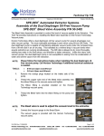
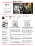
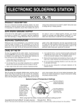
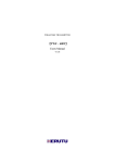
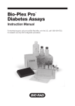
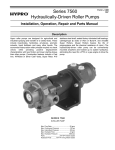
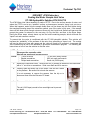
Technical Tip T68
SPE-DEX® 4790 Extractors
Coating the Water Sample Inlet Valve
ST-100 Hydrophilic Solution P/N 165-0712
The 4790 Water Inlet Valve assembly is made of PTFE. Due to the surface tension of water, and
where the PTFE is not a very “wettable” surface, a phenomenon termed a Vapor Lock can occur.
When this happens, water from the sample bottle does not flow down into the Disk Holder during
the sample-processing step of the extraction method, even if the valve is fully open. If the sample
does not flow down quick enough or does not flow at all, the Liquid Level Sensors will warm-up and
prompt the system to advance to the next step, Air Dry the disk, and then to the Rinse steps.
During the Rinse steps, solvent shoots up into the bottle containing sample, which will break the
Vapor Lock and cause an overflow.
To prevent this, the valve is conditioned with the ST-100 hydrophilic solution. This solution will
increase the “wettability” of the surfaces of the valve, thus preventing a Vapor Lock. The coating
will lose its effect over time with usage and the valve will need to be recoated. Incorporate the
valve conditioning as part of the laboratory’s preventive maintenance program. The following are
instructions on how to use the solution to coat the valve.
NOTE: Turn the controller off.
Disconnect the controller cable.
Shut off gas supply and vacuum source.
• 5/32 inch Hex (Allen) wrench
TOOLS: • ¼ inch nut driver
• 9/32 inch open end wrench
• Bladed screwdriver
• Small vial (19/22 taper)
• Philips head screwdriver.
1.
Remove the instrument cover. Remove the five (5) screws on the back of the instrument
with a ¼” nut driver or screwdriver. Slide cover back and lift to remove.
2.
Carefully slide the sensor clip off the Down Tube and set it aside
on the platform. Be careful not to knock the sensors.
It is not necessary to remove the sensors from the clip or to
disconnect them from the Extractor PC board.
3.
Place a small vial over the end of the Down Tube.
The vial (19/22 taper) needs to form an airtight seal to prevent
any leaks.
T-68 Rev B 07APR09
Page 1 of 2
Horizon Technology, Inc. 45 Northwestern Drive
[email protected]
Salem, NH 03079
[email protected]
Tel: +1.603.893.3663
Fax: +1.603.893.4994
www.horizontechinc.com
Technical Tip T68
4.
Locate the black actuator inside the front panel of the extractor.
Facing the back of the Extractor and using a 9/32” open-end
wrench, turn the shaft on the actuator counterclockwise until the
flat side is in the vertical position.
The flat side will be on the left when looking at the actuator from
the back.
The valve is now in the open position.
5.
Pour the STD-100 Hydrophilic Solution down the valve from the Bottle Holder. Pour
enough solution to fill the narrow opening to the top, where the Bottle Holder begins.
6.
Using the open-end wrench, turn the actuator shaft back to the closed position (flat side
of shaft horizontal). Turn it back to the fully open position. Repeat two or three times.
7.
Turn the actuator shaft approximately ¼ of the way to slightly open the valve. Leave the
valve in this position.
8.
Pour more hydrophilic solution into the valve if the level has dropped below the top
narrow opening of the Bottle Holder.
9.
Let the water inlet valve sit overnight with the solution.
10. Using the open-end wrench, turn the actuator shaft to completely open the valve. The flat
side of the key will be on the left when facing the back of the extractor. Place a large
beaker on the platform below the Down Tube to prevent the solution from spilling onto the
extractor. Remove the vial and allow the solution to completely drain into the beaker.
11. Turn the actuator shaft back in the horizontal position to completely close the valve.
12. Carefully slide the Thermistor clip onto the Down tube
and up to a middle position on the Down tube while
holding the platform down. Be careful not to knock the
sensors as this could cause damage.
13. Adjust Sensor Heights. The sensors should be
staggered by a distance of one sensor bead.
The sensors should be placed high enough on the Down
Tube so that the disk does not go dry during the Prewet
soak. Final adjustment can be made once a Disk Holder
is in position.
14. Install the cover. Ensure the top cover tabs captures the front panel and the cover side
tabs are inside the front panel. Fasten with five (5) screws.
15. Reconnect the Controller cable. Follow Start Up procedure in User’s Manual
Replacement parts available from Horizon Technology Inc.
50-2457
Sample Bottle Holder
48-2608
Rinse Tube (quantity 2) Service Kit
48-2606
Dispense Ring/Tube Assembly Service Kit
T-68 Rev B 07APR09
Page 2 of 2
Horizon Technology, Inc. 45 Northwestern Drive
[email protected]
Salem, NH 03079
[email protected]
Tel: +1.603.893.3663
Fax: +1.603.893.4994
www.horizontechinc.com