1
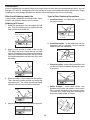
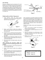
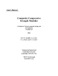
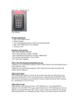
ELECTRONIC SOLDERING STATION
MODEL SL-75
PRODUCT DESCRIPTION
The SL-75 Electronic-Controlled Soldering Station has been
developed to meet the present needs of the electronics industry.
It incorporates an electronic circuit which enables the user to
change the tip temperature from 350OF to 900OF without the need
to change the tip or heating element.
ANTI-STATIC GROUND OUTPUT
At the back of the solder station is a ground output binding post.
Its purpose is to protect IC’s, transistors, and other equipment
from static discharge or voltage differentials. When you think you
are going to work on voltage-sensitive devices, you should
connect an anti-static wrist strap (Elenco® model WS-1) or antistatic work mats (Elenco® model WS-2) to the binding post.
WORKING TEMPERATURE
Soldering at the correct temperature is very important to ensure
a perfect solder connection. If the temperature is too low, the
solder will not flow correctly and will cause cold solder joints. If the
temperature is too high, the flux will be burned and not allow the
solder to flow. High temperature can also cause damage to the
PC board and other sensitive components. When the tip working
temperature is set within the correct parameters suited to the
particular solder being used, a good joint is assured.
CARE OF THE TIP
4. If an oxide film forms, it can be cleaned by lightly rubbing with
a 600-800 grit emery cloth. Then, immediately reheat and retin the tip to prevent oxidation of the wettable surface.
Two tips are supplied with this solder station. A general-purpose
conical tip SR-1NT to do most of your soldering requirements and
is installed in the soldering iron. For heavier duty soldering, we
have enclosed an extra wedge-type tip SL-75T2.
5. Remove the tip and clean every twenty-four hours of use, or at
least once a week. Remove any loose build-up in the barrel.
1. Always keep tips tinned before switching off or storing for any
period of time. Wipe only before use.
6. Do not use fluxes containing chloride or acid. Use only rosin
or activated resin fluxes.
2. Do not keep the iron set at high temperature for an extended
period of time as this will break down the surface of the tip.
7. Do not use any compound or anti-seize materials on the
wettable surface.
3. Never clean the tip with coarse, abrasive materials like files.
OPERATION
Wet the sponge with preferably distilled water, and then place it
into the tray. Plug the soldering iron line cord into AC receptacle.
Make sure the control knob is in the OFF position. Turn the control
knob to the ON position, setting it midway. Allow the iron to heat
up for a few minutes. Now set it to the desired temperature. See
the chart for relative temperatures. Using the lowest power setting
will protect sensitive devices.
General Areas of Temperature Settings
450
Park Position
In these settings,
temperatures are too
low for soldering. Set
the station in these
positions when not
using it to reduce
oxidation of the
soldering iron tip.
Use these settings for
soldering temperature
sensitive components.
350
600
700
Use these settings for
general soldering and
connections that
require more heat.
When using lead-free solder, increase all temperature settings by 50°F.
Copyright © 2012 by ELENCO® All rights reserved.
Revised 2012
REV-C
No part of this book shall be reproduced by any means; electronic, photocopying, or otherwise without written permission from the publisher.
753001
SAFETY PRECAUTIONS
• Always assume that the tip is hot to avoid burns.
Like all electrical devices, the solder station must be
handled with care. The soldering iron and tip can reach
high temperatures and these simple safety rules should
be followed.
• Work in an area that is well ventilated.
• Be careful that the hot soldering iron tip or the barrel
of the iron does not come in contact with any electrical
cord.
• Keep children out of reach of the soldering station.
• To protect your eyes, use safety goggles.
• Do not hold solder in your mouth. Wash your hands
thoroughly after handling solder.
• Keep flammable material away from the soldering iron.
• DO NOT cool iron by dipping it into any liquid or water.
• Locate soldering iron in an area where you do not have
to go around it or reach over it.
INTRODUCTION TO SOLDERING
Almost every electronic device today has a printed circuit
board. Whether you are assembling a PC board or
repairing it, you must understand the basics of working
with these boards.
Use these procedures to increase the life of your
soldering iron tip when using lead-free solder:
• Keep the iron tinned at all times.
• Use the correct tip size for best heat transfer. The
conical tip is the most commonly used.
A poorly soldered joint can greatly affect small current
flow in circuits and can cause equipment failure. You can
damage a PC board or a component with too much heat
or cause a cold solder joint with insufficient heat. Sloppy
soldering can cause bridges between two adjacent foils
preventing the circuit from functioning.
• Turn off iron when not in use or reduce temperature
setting when using a soldering station.
• Tips should be cleaned frequently to remove
oxidation before it becomes impossible to remove.
Use Dry Tip Cleaner (Elenco® #SH-1025) or Tip
Cleaner (Elenco® #TTC1). If you use a sponge to
clean your tip, then use distilled water (tap water has
impurities that accelerate corrosion).
Good soldering requires practice and an understanding
of soldering principles. This solder practice project will
help you achieve good soldering techniques, help you to
become familiar with a variety of electronic components,
and provide you with dynamic results.
Flux
Solder
Most solder contains flux in the hollow core of the solder
allowing it to be applied automatically when you heat the
solder. The flux will remove any oxide film on the metals
soldered creating a good metal-to-metal contact. This
is called “wetting the metal”. There are three types of
solder fluxes: chloride, organic and rosin. In the
electronics industry, only the rosin type is used. Rosin
flux comes in two types, pure and active. The most
reliable is the pure type, since it doesn’t cause dendrites
between tracks on the PC board as the active type does.
Due to the highly corrosive and moisture attracting
characteristics of the chloride and organic type fluxes,
they should not be used in electronics.
For many years leaded solder was the most common
type of solder used by the electronics industry, but it is
now being replaced by lead-free solder for health
reasons. Lead-free solder contains 99.3% tin, 0.7%
copper, and has a rosin-flux core.
Lead-free solder is different from lead solder: It has a
higher melting point than lead solder, so you need higher
temperature for the solder to flow properly.
Recommended tip temperature is approximately 700°F;
higher temperatures improve solder flow but accelerate
tip decay. An increase in soldering time may be required
to achieve good results. Soldering iron tips wear out
faster since lead-free solders are more corrosive and the
higher soldering temperatures accelerate corrosion, so
proper tip care is important. The solder joint finish will
look slightly duller with lead-free solders.
Surface Preparation
In order for the solder to adhere to the connection, the
metals must be clean and free of nonmetallic materials.
Flux in the solder can remove oxides from metal but not
other materials like dirt or grease. To remove these, use
a small steel brush or fine emery cloth.
-2-
SOLDERING
A poorly soldered joint can greatly affect small current flow in circuits and can cause equipment failure. You can
damage a PC board or a component with too much heat or cause a cold solder joint with insufficient heat. Sloppy
soldering can cause bridges between two adjacent foils preventing the circuit from functioning.
What Good Soldering Looks Like
Types of Poor Soldering Connections
A good solder connection should be bright, shiny,
smooth, and uniformly flowed over all surfaces.
1. Insufficient heat - the solder will not flow onto
the lead as shown.
Soldering a PC board
Rosin
1. Solder all components from the copper foil side
only. Push the soldering iron tip against both the
lead and the circuit board foil.
Soldering Iron
Component Lead
Soldering iron positioned
incorrectly.
Foil
2. Insufficient solder - let the solder flow over the
connection until it is covered. Use just enough
solder to cover the connection.
Circuit Board
2. Apply a small amount of solder to the iron tip.
This allows the heat to leave the iron and onto
the foil. Immediately apply solder to the opposite
side of the connection, away from the iron. Allow
the heated component and the circuit foil to melt
the solder.
Solder
Gap
Component Lead
Soldering Iron
Solder
3. Excessive solder - could make connections that
you did not intend to between adjacent foil areas
or terminals.
Foil
Solder
3. Allow the solder to flow around the connection.
Then, remove the solder and the iron and let the
connection cool. The solder should have flowed
smoothly and not lump around the wire lead.
Solder
4. Solder bridges - occur when solder runs
between circuit paths and creates a short circuit.
This is usually caused by using too much solder.
To correct this, simply drag your soldering iron
across the solder bridge as shown.
Soldering Iron
Foil
Soldering Iron
4. Here is what a good solder connection looks like.
Foil
-3-
Drag
Heat Sinking
Electronic components such as transistors, IC’s, and
diodes can be damaged by the heat during soldering.
Heat sinking is a way of reducing the heat on the
components while soldering. Dissipating the heat can
be achieved by using long nose pliers, an alligator clip,
or a special heat dissipating clip. The heat sink should
be held on the component lead between the part and
the solder joint.
Soldering iron
Solder
PC board
Heat sink
(this can be ordered as part of
Elenco’s Solder Ease Kit Model SE-1).
Heat sensitive
component (diode)
Figure 1
Soldering Surface Mount Components
After a component is completely soldered, each solder
joint should be inspected with a magnifying glass. If the
solder has not flowed smoothly, a bad solder joint is
indicated. This occurs when the component and pad
have not been heated sufficiently. To correct, reheat the
connection and if necessary add a small amount of
additional solder.
1. Using tweezers, place the surface mount
component on the PC board pads and secure in
place with tape (see Figure 2).
Tape
Iron
Another way to solder surface mount components is
as follows:
Figure 2
1. Apply a small amount of solder to the soldering
iron tip as shown in Figure 3.
Solder
2. Apply a small amount of solder to the soldering
iron tip. This allows the heat to leave the iron and
flow onto the foil.
2. Using tweezers, hold the component on the PC
board pads.
3. Apply the soldering iron simultaneously to the
component and pad and allow the solder to flow
around the component.
3. Place the iron in contact with the PC board foil.
Apply a small amount of solder simultaneously to
the foil and the component and allow them to melt
the solder.
4. Remove the soldering iron and allow the
connection to cool.
4. Remove the iron and allow the solder to cool. The
solder should have flowed freely and not lump up
around the component.
Tweezers or pliers
5. Remove the tape and solder the other side of the
component.
Soldering iron
When soldering the transistors, diodes and
integrated circuits, the following procedure may
be used:
Surface mount component
Solder
1. Place the component on the PC board pads and
secure in place with tape.
Figure 3
2. Apply a small amount of solder to the soldering
iron tip.
3. Place the soldering iron tip to the component lead
to be soldered and apply solder simultaneously to
the pad and the PC board foil.
Replacement Tips for Solder Station
SR-1NT - Conical Tip
SL-75T2 - Wedge Tip
4. Remove the iron and allow the solder to cool. The
solder should have flowed freely and not lump up
around the component.
-4-