1
SAFETY INSTRUCTIONS
(Always read these instructions before using this equipment.)
Before using this product, please read this manual and the relevant manuals introduced in this manual
carefully and pay full attention to safety to handle the product correctly.
The instructions given in this manual are concerned with this product. For the safety instructions of the
programmable controller system, please read the CPU module user's manual.
In this manual, the safety instructions are ranked as "DANGER" and "CAUTION".
DANGER
Indicates that incorrect handling may cause hazardous conditions,
resulting in death or severe injury.
! CAUTION
Indicates that incorrect handling may cause hazardous conditions,
resulting in medium or slight personal injury or physical damage.
!
Note that the ! CAUTION level may lead to a serious consequence according to the circumstances.
Always follow the instructions of both levels because they are important to personal safety.
Please save this manual to make it accessible when required and always forward it to the end user.
[Design Instructions]
!
DANGER
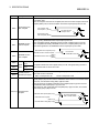
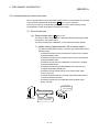
If a communication error occurs in the data link, the following will occur in the station having the
communication error.
Use the communication status information, and configure an interlock circuit in the sequence
program so that the system will operate safely.
Incorrect outputs and incorrect operations can lead to accidents.
(1) All points of the general-purpose input from this module will turn OFF.
(2) All points of the general-purpose output from this module will turn OFF.
The input/output may turn ON or OFF depending on the module trouble.
Provide a circuit that externally monitors input/output signals that could lead to serious trouble.
A-1
!
CAUTION
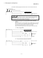
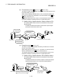
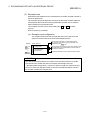
Do not bind the control wire or communication cable with the main circuit or power wire, or
place the control wire near these.
Separate by at least 100mm or more.
Failure to observe this could lead to malfunctions caused by noise.
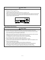
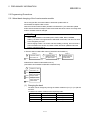
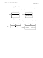
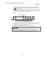
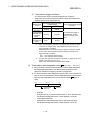
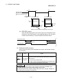
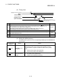
Always connect the master module and CC-Link dedicated cable at the data link terminal block.
If the data link terminal block and general-purpose input/output terminal block are incorrectly
inserted, module trouble could occur.
General-purpose input/
output terminal block
Data link terminal
block
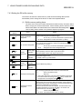
[Mounting Instructions]
!
CAUTION
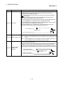
Use this module within the general specification environment described in the manual.
Use in an environment outside the general specification range could lead to electric shocks,
fires, malfunctioning, product damage or deterioration.
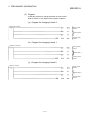
Always connect the crimp, press-fit or solder the connector wire connections with the makerdesignated tools, and securely connect the connector to the module.
An incomplete connection could lead to short-circuits or malfunctioning.
Do not directly touch the conductive section of the module.
Failure to observe this could lead to module malfunctioning or trouble.
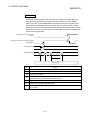
Securely fix the module with the DIN rail or installation screw. Tighten the installation screw
within the designated torque range.
A loose screw could lead to dropping, short-circuiting or malfunctioning.
If the screw is too tight, dropping or short-circuiting could occur due to screw damage.
Securely mount the connector of each connection cable to the mounting section.
An incomplete connection could lead to malfunctioning caused by an incorrect contact.
A-2
[Wiring Instructions]
!
CAUTION
Before starting installation or wiring work, be sure to shut off all phases of external power supply
used by the system.
Failure to shut off all phases could lead to electric shocks, product damage or malfunctioning.
Always install the terminal covers enclosed with the product before turning ON the power or
operating the product after installation or wiring work.
Failure to install the terminal cover could lead to electric shocks.
Always ground the FG terminal with Class D grounding (Class 3 grounding) dedicated of the
programmable controller.
Failure to do so could lead to malfunctioning.
Always confirm the product's rated voltage and terminal layout before wiring the module.
Connecting with a power supply other than the rated power supply, or incorrect wiring could
lead to fires or trouble.
Tighten the terminal screws within the specified torque range.
A loose terminal screw could lead to short-circuiting or malfunctioning.
If the terminal screw is too tight, dropping or short-circuiting could occur due to screw damage.
Make sure that foreign matter, such as cutting chips or wire scraps, do not enter the module.
Failure to observe this could lead to fires, trouble or malfunctioning.
The communication cables and power supply cable connected to the module must be placed in
a conduit or fixed with a clamp.
If the cable is not placed in a conduit or fixed with a clamp, the module or cable could be
damaged by the cable variation, movement or unintentional pulling leading to malfunctioning
caused by an improper cable connection.
Do not install the control lines together with the communication cables, or bring them close to
each other. Failure to do so may cause malfunctions due to noise.
Do not remove the communication cable or power supply cable connected to the module by
pulling on the cable section.
If the cable has a connector, hold the connector at the section connected to the module, and
remove.
If the cable does not have a connector, loosen the screws at the section connected to the
module, and remove.
Pulling on the cable while connected to the module could lead to module or cable damage, or
malfunctioning caused by an improper cable connection.
A-3
[Startup/Maintenance Instructions]
!
CAUTION
When power is ON, do not touch the terminals.
Doing so can cause an electric shock or malfunction.
Before cleaning or tightening the terminal screws and module mounting screws, be sure to shut
off all phases of external power supply used by the system.
Failure to shut off all phases could lead to module trouble or malfunctioning.
Do not touch the connector inside the lid at the front of the module.
Failure to observe this could lead to module trouble or malfunctioning.
Never disassemble or modify the module.
Failure to observe this could lead to trouble, malfunctioning, injuries or fires.
Do not drop or apply any strong impact to the module. Doing so may damage the module.
Before installing or removing the module on the panel, be sure to shut off all phases of external
power supply used by the system.
Failure to shut off all phases could lead to module trouble or malfunctioning.
Do not install/remove the terminal block more than 50 times after the first use of the product.
(IEC 61131-2 compliant)
[Disposal Instructions]
!
CAUTION
When disposing of the product, handle it as industrial waste.
A-4
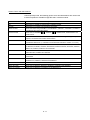
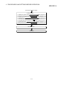
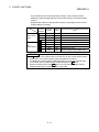
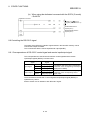
REVISIONS
* The instruction manual No. is described on the lower left of the back cover of this instruction manual.
Date of print * Instruction manual No.
Jul., 1997
Apr., 1999
Sep., 2002
IB (NA)-66781-A
IB (NA)-66781-B
IB (NA)-66781-C
Nov., 2005
IB (NA)-66781-D
Oct., 2006
IB (NA)-66781-E
Nov., 2007
IB (NA)-66781-F
Revision details
Initial print
Complete review
Equivalent to Japanese version D
Addition of description for use of the QCPU (Q mode)
Addition
Compliance with the EMC/Low Voltage Directive, Section 4.5.1,
Section 5.2.2
Deletion
Section 2.3
Partial Correction
SAFETY INSTRUCTIONS, About Manuals, Chapter 1, Section 2.1,
Section 2.2, Section 3.1, Section 3.2, Section 3.3, Section 3.4, Section
3.7, Section 4.1, Section 4.2, Section 4.4, Section 4.5.2, Section 4.5.3,
Section 4.6, Section 5.2, Section 5.6.2, Section 8.3, Section 9.1,
Section 9.2.4, Section 10.1.2, Section 10.2
Partial Correction
SAFETY INSTRUCTIONS, About Manuals, Generic Terms and
Abbreviations, Definitions and Details of Terms, Section 1.1, Section
2.1, 2.2, Section 3.1, 3.2, 3.4, 3.6.1, 3.6.2, 3.7, 3.8, 3.9.1, 3.9.2,
Section 4.2, 4.4, 4.5.2, 4.5.3, Section 5.2.1, 5.3, 5.4, 5.5.1, 5.5.2,
5.7.1, 5.7.2, 5.7.3, 5.7.4, Section 6.3.1, 6.3.2, 6.4.1, 6.4.2, Section
7.3.1, 7.4.3, 7.5.2, Section 8.2, 8.3, 8.4, 8.5, 8.9.2, Section 9.1, 9.2.1,
9.2.2, 9.2.3, 9.2.4, 9.3.2, 9.3.3, Section 10.1.2, 10.3
Addition
INDEX
Partial Correction
SAFETY INSTRUCTIONS, Section 3.2, 3.4, 4.4, 7.3
Change of a term
"PLC" was changed to "programmable controller".
Partial Correction
Section 4.2, 4.4, Section 5.1, 5.2.1, 5.5.1, 5.6.2, 5.7.3, Section 6.2,
6.3, 6.4.1, 6.4.2, Section 7.4.3, Section 8.10, Section 9.2.1, 9.2.2,
9.2.4, 9.3.1, 9.3.3, Section 10.1.2, 10.3, 10.4
Japanese Manual Version SH-3633-G
This manual does not guarantee the implementation of industrial rights or other rights, and does not authorize the
implementation rights. Mitsubishi shall not be held liable for any problems regarding industrial rights that occur through
the use of the contents given in this manual.
© 1997 MITSUBISHI ELECTRIC CORPORATION
A-5
INTRODUCTION
Thank you for purchasing the Mitsubishi general-purpose programmable controller MELSEC-A.
Always read through this manual, and fully comprehend the functions and performance of the A Series
programmable controller before starting use to ensure correct usage of this product.
Make sure that this manual is delivered to the final user.
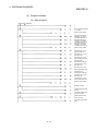
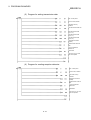
CONTENTS
Safety Instructions..........................................................................................................................................A- 1
Revisions ........................................................................................................................................................A- 5
About Manuals ...............................................................................................................................................A- 9
Compliance with the EMC/Low Voltage Directive.........................................................................................A- 9
Using This Manual.........................................................................................................................................A- 10
Generic Terms and Abbreviations ................................................................................................................A- 11
Definitions and Details of Terms...................................................................................................................A- 12
1. OUTLINE
1- 1 to 1- 4
1.1 Features ................................................................................................................................................... 1- 2
2. SYSTEM CONFIGURATION
2- 1 to 2- 2
2.1 System configuration ............................................................................................................................... 2- 1
2.2 Applicable systems .................................................................................................................................. 2- 2
3. SPECIFICATIONS
3- 1 to 3- 26
3.1 General specifications.............................................................................................................................. 3- 1
3.2 Performance specifications...................................................................................................................... 3- 2
3.3 RS-232-C interface specifications ........................................................................................................... 3- 3
3.4 General-purpose input/output specifications........................................................................................... 3- 4
3.5 List of functions ........................................................................................................................................ 3- 6
3.6 Input/output signals for master module ................................................................................................... 3- 7
3.6.1 List of input/output signals................................................................................................................. 3- 7
3.6.2 Details of input/output signals ........................................................................................................... 3- 8
3.7 R2 buffer memory list.............................................................................................................................. 3- 13
3.8 Transmission delay time ......................................................................................................................... 3- 19
3.9 Transmission/reception time................................................................................................................... 3- 20
3.9.1 When using buffer memory automatic update function .................................................................. 3- 20
3.9.2 When using transmission/reception buffer ...................................................................................... 3- 23
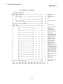
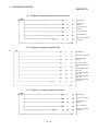
4. PROCEDURES AND SETTINGS BEFORE OPERATIION
4- 1 to 4- 12
4.1 Procedures before operation ................................................................................................................... 44.2 Precautions for handling .......................................................................................................................... 44.3 Installation environment ........................................................................................................................... 44.4 Names of each part, and settings............................................................................................................ 44.5 Wiring........................................................................................................................................................ 4A-6
1
3
5
6
8
4.5.1 Precautions for handling the CC-Link dedicated cables.................................................................. 4- 8
4.5.2 Connection of the CC-Link dedicated cables ................................................................................... 4- 8
4.5.3 Connection with external device ....................................................................................................... 4- 9
4.6 Checking the module’s state (Hardware test) ........................................................................................ 4- 11
5. PRELIMINARY INFORMATION
5- 1 to 5- 46
5.1 System used in this manual..................................................................................................................... 5- 1
5.2 Programming Precautions ....................................................................................................................... 5- 3
5.2.1 About bank changing of the A series master module ...................................................................... 5- 3
5.2.2 About dedicated commands for use of the buffer memory automatic update function .................. 5- 5
5.3 Program basic format............................................................................................................................... 5- 6
5.4 Initializing the master station.................................................................................................................... 5- 9
5.5 Initializing the R2 ..................................................................................................................................... 5- 12
5.5.1 Using the buffer memory automatic update function ...................................................................... 5- 12
5.5.2 Using the transmission/reception buffer .......................................................................................... 5- 15
5.6 Reading and writing the buffer memory (using the buffer memory automatic update function) .......... 5- 18
5.6.1 Outline............................................................................................................................................... 5- 18
5.6.2 Understanding the roles of each area ............................................................................................. 5- 19
5.7 Reading and writing the buffer memory (using the transmission/reception buffer) .............................. 5- 28
5.7.1 Outline............................................................................................................................................... 5- 28
5.7.2 About control data ............................................................................................................................ 5- 29
5.7.3 Reading the R2 buffer memory........................................................................................................ 5- 40
5.7.4 Writing to the R2 buffer memory...................................................................................................... 5- 43
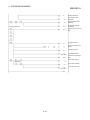
6. EXCHANGING DATA WITH AN EXTERNAL DEVICE
6- 1 to 6- 30
6.1 Matters to understand before transmitting data ...................................................................................... 6- 1
6.2 Matters to know before receiving data .................................................................................................... 6- 5
6.3 Exchanging data using the buffer memory automatic update function .................................................. 6- 9
6.3.1 Transmitting data to an external device .......................................................................................... 6- 9
6.3.2 Receiving data from an external device .......................................................................................... 6- 14
6.4 Exchanging data using the transmission/reception buffer..................................................................... 6- 18
6.4.1 Transmitting data to an external device .......................................................................................... 6- 18
6.4.2 Receiving data from an external device .......................................................................................... 6- 24
7. USING FRAMES WHEN EXCHANGING DATA
7- 1 to 7- 38
7.1 What are frames?..................................................................................................................................... 7- 1
7.2 Transmitting data using frames ............................................................................................................... 7- 2
7.2.1 Transmitting using transmission frame 1 area ................................................................................. 7- 2
7.2.2 Transmitting using the transmission frame 2 area ........................................................................... 7- 4
7.3 Receiving data using frames ................................................................................................................... 7- 6
7.3.1 Reception data .................................................................................................................................. 7- 8
7.3.2 Reading the reception data.............................................................................................................. 7- 10
7.4 Transmitting data at the device and status change ............................................................................... 7- 13
7.4.1 Outline............................................................................................................................................... 7- 13
7.4.2 Devices and statuses that can be designated................................................................................. 7- 14
7.4.3 Setting the R2 buffer memory.......................................................................................................... 7- 15
A-7
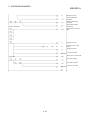
7.4.4 Precautions....................................................................................................................................... 7- 21
7.5 Registration frames................................................................................................................................. 7- 22
7.5.1 List of default registration frames..................................................................................................... 7- 23
7.5.2 Details of user registration frames................................................................................................... 7- 25
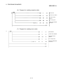
8. OTHER FUNCTIONS
8- 1 to 8- 24
8.1 Canceling data communication to an external device ............................................................................ 8- 1
8.2 Forcibly completing reception .................................................................................................................. 8- 3
8.3 Flow control .............................................................................................................................................. 8- 6
8.4 ASCII-BIN conversion of transmission data........................................................................................... 8- 10
8.5 RW update function ................................................................................................................................ 8- 12
8.6 Initializing the R2 ..................................................................................................................................... 8- 15
8.7 Clearing the OS reception area .............................................................................................................. 8- 16
8.8 Registering and initializing the R2 EEPROM ......................................................................................... 8- 19
8.9 Controlling the RS-232-C signal ............................................................................................................. 8- 22
8.9.1 Correspondence of RS-232-C control signal and remote input/output signal ............................... 8- 22
8.9.2 Precautions for using RS-232-C control signal read/write function................................................ 8- 23
8.10 Confirming the R2 switch states and software version........................................................................ 8- 24
9. PROGRAM EXAMPLES
9- 1 to 9- 48
9.1 Conditions for program examples ........................................................................................................... 9- 1
9.2 Example of program for using buffer memory automatic update function ............................................. 9- 2
9.2.1 When using FROM/TO command with ACPU / QCPU-A (A mode) ............................................... 9- 2
9.2.2 When using dedicated commands with ACPU / QCPU-A (A mode) .............................................. 9- 6
9.2.3 When using dedicated commands with QCPU (Q mode) / QnACPU............................................ 9- 11
9.2.4 When using the FROM/TO commands with ACPU / QCPU-A (A mode)
(Three R2 modules connected) ...................................................................................................... 9- 14
9.3 Example of program for using transmission/reception buffer................................................................ 9- 28
9.3.1 When using FROM/TO command with ACPU / QCPU-A (A mode) .............................................. 9- 28
9.3.2 When using dedicated commands with ACPU / QCPU-A (A mode) ............................................. 9- 37
9.3.3 When using dedicated commands with QCPU (Q mode) / QnACPU............................................ 9- 43
10. TROUBLESHOOTING
10- 1 to 10- 12
10.1 Error codes........................................................................................................................................... 10- 1
10.1.1 Error code storage area ................................................................................................................ 10- 1
10.1.2 List of error codes.......................................................................................................................... 10- 2
10.2 Confirming the error with the LED ....................................................................................................... 10- 5
10.3 Examples of trouble in general-purpose input circuit.......................................................................... 10- 7
10.4 Troubleshooting per symptom ............................................................................................................. 10- 9
10.5 Troubleshooting when the master station's ERR. LED flashes......................................................... 10- 10
APPENDIX
Appendix- 1 to Appendix- 2
Appendix 1 Outline dimension drawing ............................................................................................Appendix- 1
INDEX
INDEX- 1 to INDEX 3
A-8
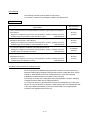
About Manuals
The following manuals are also related to this product.
In necessary, order them by quoting the details in the tables below.
Related Manuals
Manual Number
Manual Name
(Model Code)
Control & Communication Link System Master/Local Module Type AJ61BT11/A1SJ61BT11
User's Manual
IB-66721
Explains the configuration, performance and specifications, functions, handling, wiring and
(13J872)
troubleshooting of the AJ61BT11 and A1SJ61BT11 system.
(Sold separately)
Control & Communication Link System Master/Local Module Type
AJ61QBT11/A1SJ61QBT11 User's Manual
IB-66722
Explains the configuration, performance and specifications, functions, handling, wiring and
troubleshooting of the AJ61QBT11 and A1SJ61QBT11 system.
CC-Link System Master/Local Module User's Manual QJ61BT11N
Explains the configuration, performance and specifications, functions, handling, wiring and
troubleshooting of the QJ61BT11N system.
(13J873)
(Sold separately)
(Sold separately)
SH-080394E
(13JR64)
AnSHCPU/AnACPU/AnUCPU/QCPU-A (A mode) Programming Manual QJ61BT11
(Dedicated Instructions)
IB-66251
Explains the configuration, performance and specifications, functions, handling, wiring and
troubleshooting of the QJ61BT11 system.
(13J742)
(Sold separately)
Compliance with the EMC/Low Voltage Directive
When incorporating the Mitsubishi programmable controller into other machinery or
equipment and keeping compliance with the EMC and low voltage directives, refer to
Chapter 3, "EMC Directives and Low Voltage Directives" of the User's Manual
(Hardware) included with the CPU module or base unit used.
The CE logo is printed on the rating plate of the programmable controller, indicating
compliance with the EMC and low voltage directives.
To conform this product to the EMC Directive and Low Voltage Directive, refer to the
Section of "CC-Link Modules" in Chapter 3 "EMC Directive and Low Voltage Directive"
in the User’s Manual (Hardware) of the CPU module used or the programmable
controller CPU supplied with the base unit.
A-9
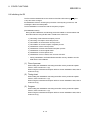
Using This Manual
This section "Using this manual" describes the R2 usage in categories of purpose.
Refer to the following details when using this manual.
(1) To find the characteristics of R2 (Section 1.1)
The features are described in section 1.1.
(2) To find the system configuration (Section 2.1)
The configuration of a system using R2 is explained in section 2.1.
(3) To find the master module that can use R2, and the CPU version that can use the
CC-Link dedicated commands (Section 2.2)
The master module that can use R2, and the CPU version that can use the CCLink dedicated commands are explained in section 2.2.
(4) To find the R2 specifications (Chapter 3)
The R2 specifications are described in Chapter 3.
(5) To find the time for transmitting/receiving data with R2 (Sections 3.8, 3.9)
The R2 transmission delay time and transmission/reception time are explained in
sections 3.8 and 3.9.
(6) To find the procedures for operating R2 (Chapter 4)
The procedures for operating the R2, and the methods of checking the module
state are explained in Chapter 4.
(7) To find how to access the R2 buffer memory (Sections 5.6, 5.7)
The methods of accessing the buffer memory are described in sections 5.6 and
5.7.
(8) To exchange data with an external device (Chapter 6)
The methods of exchanging data with an external device are explained in Chapter
6.
(9) To add a frame when exchanging data (Chapter 7)
The details of the frame, and the methods of adding a frame are explained in
Chapter 7.
(10) To find sample programs (Chapter 9)
Sample programs are described in Chapter 9.
(11) When trouble occurs (Chapter 10)
The error code list and troubleshooting are described in Chapter 10.
"How to Use This Manual" is described by purposes of using CSKP.
Refer to the following and use this manual.
A - 10
Generic Terms and Abbreviations
Unless specially noted, the following generic terms and abbreviations are used in this
manual to explain the AJ65BT-R2 type RS-232-C interface module.
Generic term/abbreviation
Details of generic term/abbreviation
R2
Abbreviation for AJ65BT-R2 type RS-232-C interface module.
CC-Link
Abbreviation for Control & Communication Link system.
Master module
Generic term when using AJ61QBT11, A1SJ61QBT11, AJ61BT11, A1SJ61BT11, QJ61BT11
and QJ61BT11N as the master station.
Remote module
Generic term for AJ65BTB -
, AJ65BTC -
, AJ65BT-64AD, AJ65BT-64DAV and
AJ65BT-64DAI.
External device
Generic term for devices such as ID controller, bar code reader and general-purpose personal
computer, connected to R2 for data communication.
GPPW
Generic term for model names: SWnD5C-GPPW, SWnD5C-GPPW-A, SWnD5C-GPPW-V
and SWnD5C-GPPW-VA. (“n” included in the model name indicates a number “4” or more.)
AnNCPU
Abbreviation of A0J2HCPU, A1SCPU, A1SCPUC24-R2, A1SHCPU, A1SJCPU, A1SJCPUS3, ASJHCPU, A1NCPU, A2CCPU, A2CCPUC24, A2CCPUC24-PRF, A2CJCPU, A2NCPU,
A2NCPU-S1, A2SCPU, A2SHCPU and A2FXCPU
AnACPU
Abbreviation of A2ACPU, A2ACPU-S1, A2ACPUP21/R21, A2ACPUP21/R21-S1,
A3ACPUP21/R21, A3NCPU and A3ACPU
AnUCPU
Abbreviation of A2UCPU, A2UCPU-S1, A2USCPU, A2USCPU-S1, A2USHCPU-S1, A3UCPU
and A4UCPU
QnACPU
Abbreviation of Q2ACPU, Q2ACPU-S1, Q2ASCPU, Q2ASCPU-S1, Q2ASHCPU,
Q2ASHCPU-S1, Q3ACPU, Q4ACPU and Q4ARCPU
ACPU
Abbreviation of AnNCPU, AnACPU and AnUCPU
QCPU (Q mode)
Generic term for Q02CPU, Q02HCPU, Q06HCPU, Q12HCPU and Q25HCPU
QCPU-A (A mode)
Generic term for Q02CPU-A, Q02HCPU-A and Q06HCPU-A
A - 11
Definitions and Details of Terms
The definitions and details of terms used in this manual are explained below.
(1)
M
H
This indicates the buffer memory address of the master station.
(2)
R2
H
This indicates the buffer memory address of R2.
(3) Master station
The station that controls the remote station, local station and intelligent device
station.
(4) Intelligent device station
Slave station on CC-Link system that can carry out transient transmission with R2,
etc.
(5) Transient transmission
Function that communicates data with a designated station when access is
requested from the programmable controller CPU, etc.
(6) Buffer memory automatic update function
Function that automatically updates the data between the R2 buffer memory and
master stations' automatic update buffer.
(7) Automatic update buffer
Buffer memory in master station used for the buffer memory automatic update
function in respect to R2.
(8) Registration frame
Row of data targeted for the fixed format section of the statement transmitted and
received between the external device and R2.
The registration frames include the default registration frame registered in the R2,
and the user registration frame registered by the user using EEPROM.
(9) Transmission frame 1 area
Buffer memory address R 2 118H to 119H.
With frame transmission that uses the transmission frame 1 area, a frame can be
added each to the head and end of a random data item when transmitting the
data.
(10) Transmission frame 2 area
Buffer memory address R 2 120H to 185H.
With frame transmission that uses the transmission frame 2 area, up to 100
frames can be added when transmitting the data.
A - 12
1 OUTLINE
MELSEC-A
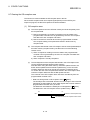
1. OUTLINE
1
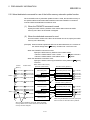
This User's Manual explains the features and specifications of the R2 used as the
intelligent device station of the CC-Link, communication with an external device, and
the special specifications, etc.
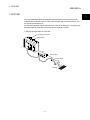
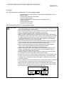
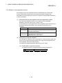
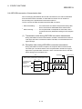
R2 can exchange data with an external device, such as an RS-232-C connection type
barcode reader, ID controller or general-purpose personal computer.
When a barcode reader is connected
Programmable controller
Master station
R2
Data reception
Barcode reader
Reading!
1-1
1 OUTLINE
MELSEC-A
1.1 Features
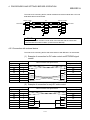
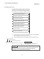
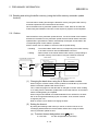
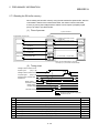
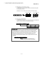
(1) Easy communication by using the buffer memory automatic update
function.
This function automatically updates the buffer memory between the R2 and
master station at the timing set in R2.
With this, a program to read and write between the R2 and master station can be
eliminated. As the data can be read and written with just the FROM/TO
command, the program is simplified.
(This can be used with all CPUs.)
Carried out with sequence program
Programable controller CPU
Master station
Automatically updated
R2
1)
TO
2)
Buffer memory
(Automatic
update
buffer *1)
FROM
4)
Buffer
memory
3)
*1 The address differs as shown below
for the A Series and Q/QnA Series.
A Series
: Bank 2 M 0H to FFFH
Q/QnA Series : M 2000H to 2FFFH
1)
2)
3)
4)
The data to be stored in the R2 buffer memory is written into the master
station's automatic update buffer.
The data is automatically written in at the R2 timing.
The data is automatically read at the R2 timing.
The corresponding master station's buffer memory is read to the data in the
R2 buffer memory to be read out.
1-2
1 OUTLINE
MELSEC-A
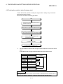
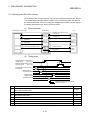
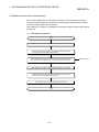
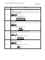
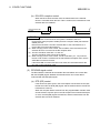
(2) Addition of frame during data transmission/reception with external
device
By adding a frame to the head and end, a statement format matching the
specifications of the external device, such as the barcode reader or ID controller,
can be created and communicated.
The frames include those that are set as the default, and the frames that can be
randomly created by the user (user registration frame).
A random frame can be added!
Random data
Data transmission
Random data
R2
External device such as barcode reader,
ID controller, general-purpose personal computer
Data reception
(3) Automatic transmission possible when user-set transmission
conditions are established
When the user-designated transmission conditions (changes in RX, RY, RW,
etc.), are established, data can be automatically transmitted to the external
device.
Master station
Monitors the status
of RX, RY and RW,
etc.
Final frame
Head frame
Random data
R2
Transmit data after conditions
are established!
External device such as barcode reader,
ID controller, general-purpose personal computer
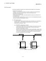
(4) Two general-purpose input/output points each provided as a
standard
Two points each are provided for the general-purpose input and output so the
synchronous signal with the barcode reader and ID controller, etc., can be
directly input and output without providing a separate remote I/O module.
1-3
1 OUTLINE
MELSEC-A
MEMO
1-4
2 SYSTEM CONFIGURATION
MELSEC-A
2. SYSTEM CONFIGURATION
The system configuration for using R2 is shown explained in this section.
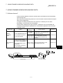
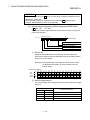
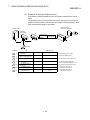
2.1 System configuration
2
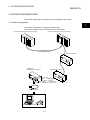
The system configuration for using R2 is shown below.
Up to 26 R2 modules can be connected to one master station.
CC-Link master/local station (master station)
CC-Link master/local station (local station)
CC-Link dedicated cable
Remote I/O station
AJ65BT-R2
(Intelligent device station)
Remote device station
1-station occupation
RX/RY
32 points each
RWr/RWw 4 points each
RS-232-C cable
Personal computer Bar code reader
External device
2-1
2 SYSTEM CONFIGURATION
MELSEC-A
2.2 Applicable systems
The master module of the CC-Link system that can use R2, and the programmable
controller CPU that can use the CC-Link dedicated commands are explained in this
section.
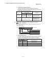
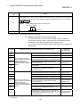
(1) Applicable master modules
The following indicates the master modules that can use the R2.
AJ61BT11
A1SJ61BT11
AJ61QBT11
A1SJ61QBT11
QJ61BT11N
QJ61BT11
POINT
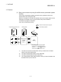
When using any of the AJ61BT11, A1SJ61BT11, AJ61QBT11 and A1SJ61QBT11,
use the one that has the following number (9707 B or later) in the DATE field of the
rating plate.
The module that does not have "9707 B" in the DATE field cannot use the R2.
<Large type>
<Compact type>
Date of
Function version
manufacture
Date of
Function version
manufacture
(2) Restrictions on use of CC-Link dedicated commands
Depending on the used programmable controller CPU and master module, the
CC-Link dedicated commands may be unusable.
For details of the restrictions, refer to the A Series Master Module User's Manual
(Details) and AnSHCPU/AnACPU/AnUCPU Programming Manual (Dedicated
Instructions).
For program examples using the dedicated commands, refer to Section 9.2.2,
Section 9.2.3, Section 9.3.2 and Section 9.3.3.
2-2
3 SPECIFICATIONS
MELSEC-A
3. SPECIFICATIONS
3.1 General specifications
The general specifications of the R2 are shown below.
Item
Specifications
Working ambient
0 to 55°C
temperature
Storage ambient
-20 to 75°C
temperature
3
Working ambient humidity
10 to 90%RH, with no dew condensation
Storage ambient humidity
10 to 90%RH, with no dew condensation
When there is
JIS B 3502,
Vibration resistance
intermittent
IEC 61131-2 vibration
compliant
When there is
continuous
vibration
Impact resistance
Frequency
Acceleration
Amplitude
10 to 57Hz
–
0.075mm
57 to 150Hz
9.8m/s
–
10 to 57Hz
–
0.035mm
57 to 150Hz
4.9m/s
2
2
–
No. of sweeps
10 times each in
X, Y and Z
directions
(for 80 minutes)
2
JIS B 3502, IEC 61131-2 compliant (147m/s , 3 times each in X, Y and Z directions)
Working atmosphere
Working altitude *3
No corrosive gases
Installation place
Overvoltage category *1
Inside control panel
2000m or less
II or less
Degree of contamination
*2
2 or less
*1 Indicates to which power distribution section, from the public power distribution network to the in-plant
machine device, the device is assumed to be connected.
Category II applies to a device fed power from a fixed facility.
The withstand surge voltage level for a device with a rating up to 300V is 2500V.
*2 Exponential indicating the degree of conductive matter generated in the environment where device is
used.
In the degree of contamination level 2, only non-conductive contaminants are generated. However,
temporary conductivity could occur due to rare condensation.
*3 Do not use or store the programmable controller in the environment where the pressure is higher than the
atmospheric pressure at sea level. Otherwise, malfunction may result. To use the programmable controller
in high-pressure environment, contact your nearest Mitsubishi representative.
3-1
3 SPECIFICATIONS
MELSEC-A
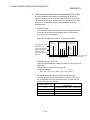
3.2 Performance specifications
The R2 performance specifications are shown below.
(1) RS-232-C specifications
Item
Specifications
Interface specifications
RS-232-C compliant, 1 channel (Refer to section 3.3)
Transmission method
Full duplex communication method
Synchronization method
Start-stop synchronization method
Transmission speed
300, 600, 1200, 2400, 4800, 9600, 19200bps
(Select with RS-232-C transmission specification setting switch)
Data format
Star bit
1
Data bit
7/8
Parity bit
1 (Yes)/0 (No)
Stop bit
1/2
Error detection
With parity check (even/odd)/None
Communication control
DTR/DSR (ER/DR) control
(flow control)
DC1/DC3 control
Transmission distance
15m
OS reception area
5120 bytes
(2) Data link specifications
Item
Specifications
General-purpose input/output Input side
specifications
: 24VDC (Positive common/negative common shared type) 2 points
Output side : Transistor output (sink type) 12/24VDC 2 points Terminal block (Refer to
section 3.4)
Transmission path
Bus (RS-485)
EEPROM writing life
100,000 times
CC-Link station type
No. of occupied stations
Intelligent device station
1 station (RX/RY 32 points each, RWw/RWr 4 points each)
Connection cable
Withstand voltage
Insulation resistance
CC-Link dedicated cable
One minute at 500VAC between DC external terminal batch and grounding
10MΩ or more with 500VDC insulation resistance meter between DC external terminal
batch and grounding
Noise withstand level
DC type noise voltage 500Vp-p
With noise width 1μs, noise frequency 25 to 60Hz noise simulator
Module installation screw
M4 × 0.7mm × 16mm or more screw
(Tightening torque range 0.78 to 1.18N⋅ m)
Applicable DIN rail
External power supply
TH35-7.5Fe, TH35-7.5Al, TH35-15Fe (JIS C 2812 compliant)
24VDC
Current consumption: 0.11A
Tolerable instantaneous
1ms
power failure time
Weight
0.40kg
3-2
3 SPECIFICATIONS
MELSEC-A
3.3 RS-232-C interface specifications
The specifications of the RS-232-C interface for connection with an external device are
shown below.
1
2
3
4
5
Pin
No.
6
7
8
Name
Signal
abbrev.
9
The following type of connector
is mounted on the R2 side, so
use a mate connector that
matches this type.
9-pin D-SUB (female) screwfixed type
DDK Ltd.
17L-10090-27-D9AC
1
Reception carrier
detection
Signal direction
R2
external
device
CD
2
Reception data
RD(RXD)
3
Transmission data
SD(TXD)
4
Data terminal ready
ER(DTR)
5
Signal ground
SG
6
Data set ready
DR(DSR)
7
Transmission request RS(RTS)
8
Transmission enable
9
Not used
CS(CTS)
–
–
The details of each signal are explained below.
CD.................. The CD signal status can be read with the input signal RXnB.
ER (DTR)....... When using DTR/DSR control, this is turned ON and OFF according
to the empty size of the OS reception area for storing the received
data.
(The DTR signal turns ON when the RS can receive data.)
When not using DTR/DSR control, the output signal RYnA is followed.
DR (DSR) ...... When using DTR/DSR control, if this is OFF, data will not be
transmitted from R2 to the external device.
Set this to be always ON when the external device is in the reception
enabled state.
When not using DTR/DSR control, the DSR signal status will be
ignored.
RS .................. This follows the R 2 101H setting and output signal RYn9.
CS .................. When the CS signal is OFF, data will not be transmitted from R2 to
the external device.
Set this to be always ON when the external device is in the reception
enabled state.
A standard connection example of the RS-232-C cable is given in section 4.5.2.
3-3
3 SPECIFICATIONS
MELSEC-A
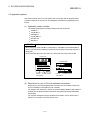
3.4 General-purpose input/output specifications
The general-purpose input/output specifications of the R2 are shown below.
(1) General-purpose input specifications
DC input (Positive common/negative common shared type)
R2
No. of input points
External connection view
2 points
Insulation method
Photo coupler insulation
Rated input voltage
24VDC
Rated input current
Approx. 7mA
Working voltage range
19.2 to 28.8VDC (ripple rate within 5%)
Max. No. of simultaneous
input points
1 XC
24VDC
100%
ON voltage/ON current
14V or more/3.5mA or more
OFF voltage/OFF current
6V or less/1.7mA or less
Input resistance
Approx. 3.3kΩ
Response
OFF
ON
10ms or less
time
ON
OFF
10ms or less
Internal
circuit
2 COM1
3 XD
2 points/common (COM1)
Common method
Positive common/negative common shared
type
External connection
method
Applicable wire size
Applicable crimp terminal
7-point terminal block (M3.5 screw)
2
0.75 to 2mm
RAV1.25-3.5, RAV2-3.5 (JIS C 2805
compliant)
3-4
Terminal
Signal
Terminal
Signal
No.
name
No.
name
TB1
XC
TB3
XD
TB2
COM1
TB4
NC
3 SPECIFICATIONS
MELSEC-A
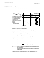
(2) General-purpose output specifications
Transistor output (sink type)
R2
No. of output points
2 points
Insulation method
Photo coupler insulation
Rated load voltage
12/24VDC
Working load voltage
10.2 to 28.8VDC (ripple rate within 5%)
Max. load current
0.1A/point 0.2A/common
Max. rush current
0.4A 10ms or less
Leakage current at OFF
0.1mA or less
Max. voltage drop at ON
1.5VDC or less (MAX) 0.1A
Output type
Sink type
OFF
time
ON
L
12/24VDC
6
ON 2ms or less
L
COM2
7 YD
OFF 2ms or less (resistance load)
Output section Voltage
externally
10.2 to 28.8VDC (ripple rate within 5%)
supplied
50mA or less (TYP. 24VDC, per common)
power
5 YC
Internal
circuit
range
Response
External connection view
Current
Not including external load current.
Surge killer
Zener diode
Common method
2 points/common (COM2)
External connection
method
Applicable wire size
Applicable crimp terminal
7-point terminal block (M3.5 screw)
2
0.75 to 2mm
RAV1.25-3.5, RAV2-3.5 (JIS C 2805
compliant)
3-5
Terminal
Signal
Terminal
Signal
No.
name
No.
name
TB5
YC
TB7
YD
TB6
COM2
3 SPECIFICATIONS
MELSEC-A
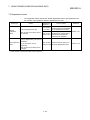
3.5 List of functions
The R2 functions are shown below.
Function
Main
function
Explanation
Non-procedural Non-procedural data transmission/reception with external
communication device such as barcode reader, ID controller, generalfunction
purpose personal computer.
Relation with
main function
Trans- Recepmission
tion
–
–
Buffer memory Automatically updates the buffer memory between the R2
automatic
and master station at the update timing set in each area of
update
the R2 buffer memory.
Reference
Chapter 6
Section 5.6
Frame addition
Adds a frame registered for R2 at the head and end of the
transmission data when transmitting data.
Chapter 7
Monitor
transmission
Automatically transmits data to the external device when the
user-designated transmission conditions (changes in RX, RY,
RW and status) are established.
Section 7.4
Transmission
cancellation
After transmission request is issued from the master station
to R2, forcibly cancels the transmission before R2 completes
transmission to external device.
Section 8.1
Forced
reception
complete
Forcibly completes the reception when reception data from
external device has not reached the reception complete data
size, etc., and reads out the currently received data.
Section 8.2
Flow control
Auxiliary
functions
Stops/resumes transmission of data from external device
according to open space in R2 OS reception area.
Section 8.3
Stops/resumes transmission of data from R2 according to
requests from external device.
ASCII-BIN
conversion
Carries out ASCII-BIN conversion on the
transmitted/received data.
Section 8.4
RW update
Assigns master station remote register (RW) and R2 side
area to be automatically updated in the buffer memory.
Section 8.5
R2 initialization Initializes the R2.
Section 8.6
OS reception
area clear
Section 8.7
Registration to
RS EEPROM
RS-232-C
signal control
Clears the received data stored in the R2 OS reception area.
Registers a setting value for the R2 buffer memory's specific
application area in the EEPROM, or returns the value
registered in the EEPROM to the R2 default value.
Section 8.8
The value for the R2 buffer memory registered in the
EEPROM (including the setting values changed by the user)
is used as an initial value at the time of the R2 startup.
Reads the status of the RS-232-C interface signal
stored in the R2 buffer memory, and controls the
output.
Section 8.9
: Related,
3-6
: Not related
3 SPECIFICATIONS
MELSEC-A
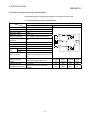
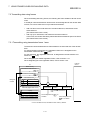
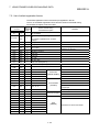
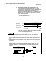
3.6 Input/output signals for master module
The input/output signals (RX/RY) for the R2 master module are explained in this
section.
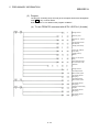
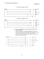
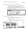
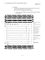
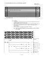
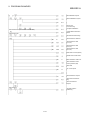
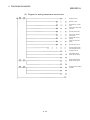
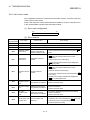
3.6.1 List of input/output signals
A list of the R2 input/output signals is shown below.
Signal direction Master module
R2
Device No. (input)
Signal name
RXn0
RXn1
RXn2
RXn3
RXn4
RXn5
RXn6
RXn7
RXn8
Transmission normal complete
Transmission error complete
Reception normal read request
Reception error read request
Initialization normal complete
Initialization error complete
OS reception area clear complete
EEPROM function normal complete
EEPROM function error complete
RXn9
RXnA
RXnB
RXnC to RXnD
RXnE to RX(n+1)8
RX(n+1)9
RX(n+1)A
RX(n+1)B
RX(n+1)C to
RX(n+1)D
RX(n+1)E
RX(n+1)F
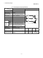
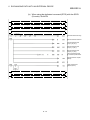
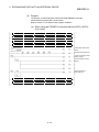
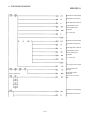
Signal direction Master module
R2
Device No. (output)
Signal name
Signal status
RYn0
RYn1
RYn2
RYn3
RYn4
RYn5
RYn6
RYn7
RYn8
CS (CTS) signal
RYn9
DR (DSR) signal
RYnA
CD signal
General-purpose external input signal
Use prohibited
Initial data read complete
Error state
Remote station ready
RYnB
RYnC to RYnD
RYnE to RY(n+1)8
RY(n+1)9
RY(n+1)A
Transmission request
Transmission cancel request
Reception read complete
Forced reception complete request
Initialization request
Use prohibited
OS reception area clear request
EEPROM function request
Use prohibited
RS (RST) signal *1
Signal setting
ER (DTR) signal *2
Use prohibited
General-purpose external output signal
Use prohibited
Initial data read request
Error reset request
RY(n+1)B to RY(n+1)D Use prohibited
Use prohibited
Intelligent device station access complete
Use prohibited
RY(n+1)E
RY(n+1)F
Intelligent device station access request
Use prohibited
n: Address assigned to master module with station No. setting.
*1
The RS signal setting is valid when the "RS signal status designation ( R 2 101H)" is set to "Follow
*2
RYn9 ON/OFF (1)". (Refer to section 8.9.)
The ER signal setting is invalid when the "Flow control designation ( R 2 100H)" is set to "Carry out
flow control. (DTR/DSR/ (ER/DR) control) (1)".
Important
Do not designate the RXn0 to RXn8, RXnE to RX(n+1)F, RYn0 to RYn9, RYnB, or RYnE to
RY (N+1)F signals to the following functions.
Monitor target RX/RY for monitor transmission function
Reference RX/RY for registration frame RX/RY/RW reference special character.
Do not output (turn ON) the usage-prohibited signals.
If an output is carried out to a usage-prohibited signal, the programmable controller system
could malfunction.
3-7
3 SPECIFICATIONS
MELSEC-A
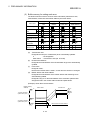
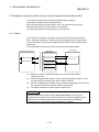
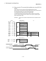
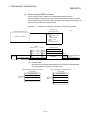
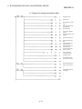
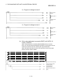
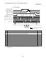
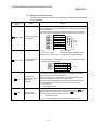
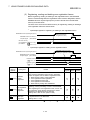
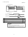
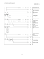
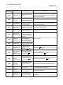
3.6.2 Details of input/output signals
A detailed explanation of the R2 input/output signals is given below.
The lines in the timing chart indicate the following details.
(1) Remote input (RX)
Device No.
RXn0
Signal name
Details
When transmitting data to an external device connected to R2, after the transmission
data is written into the R2 transmission area, the transmission request (RYn0) is
turned ON.
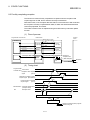
Transmission normal When the transmission is completed normally, transmission normal complete (RXn0)
turns ON, and if the transmission is completed abnormally, transmission error
complete
complete (RXn1) turns ON.
The transmission request (RYn0) turns OFF when these signals turn ON.
Transmission request (RYn0)
RXn1
RXn2
RXn3
RXn4
Transmission error
complete
Reception normal
read request
Reception error read
request
Initialization normal
complete
Transmission normal complete
(RXn0)
or Transmission error complete
(RXn1)
R2 transmits contents
of transmission area to
external device.
When data is received from an external device connected to R2 and the transmission
is completed normally, reception normal read request (RXn2) turns ON. If the
transmission is completed abnormally, reception error read request (RXn3) turns ON.
The reception data is stored in the R2 reception area at this time.
The data in the R2 reception area is read out when these signals turn ON, and read
complete (RYn2) turns OFF when the reading is completed.
Reception normal read request
(RXn2)
or Reception error read request
(RXn3)
Reception area is read
with sequence program.
Reception read complete (RYn2)
The initialization request (RYn4) is turned ON to initialize R2.
When the R2 is correctly initialized, initialization correct complete (RXn4) turns ON,
and when the process ends abnormally, initialization error complete (RXn5) turns ON.
The initialization request signal (RYn4) turns OFF when these signals turn ON.
Initialization request (RYn4)
RXn5
Initialization error
complete
Initialization normal complete
(RXn4)
or Initialization error complete
(RXn5)
3-8
R2 is initialized.
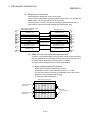
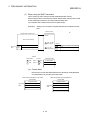
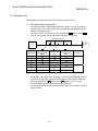
3 SPECIFICATIONS
Device No.
MELSEC-A
Signal name
Details
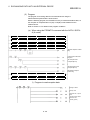
The OS reception area clear request (RYn6) is turned ON to abort the data in the R2
OS reception area.
When OS reception area clear is completed, the R2 turns the OS reception area clear
complete (RXn6) ON, so the OS reception area clear request (RYn6) will turn OFF.
RXn6
OS reception area
clear complete
OS reception area
clear request (RYn6)
R2 clears the OS
reception area.
OS reception area
clear complete (RXn6)
RXn7
EEPROM function
normal complete
When the R2 EEPROM function is executed, after the data is read into the R2 buffer
memory (1C0H), EEPROM function request (RYn7) turns ON.
When completed normally, EEPROM function normal complete (RXn7) turns ON.
When completed abnormally, EEPROM function error complete (RXn8) turns ON.
When these signals turn ON, EEPROM function request (RYn7) turns OFF.
EEPROM function request (RYn7)
RXn8
EEPROM function
error complete
RXn9
CS (CTS)
signal
RXnA
Signal
DR (DSR)
status
signal
RXnB
CD signal
RXnC
RXnD
General-purpose
external input signal
EEPROM function normal complete
(RXn7)
or EEPROM function error complete
(RXn8)
R2 executes
EEPROM function.
This signal indicates the control signal status (CS, DR, CD signal) during RS-232-C
communication with an ON or OFF state.
This signal indicates the status of the R2 general-purpose external input (XC, XD)
status with an ON or OFF state.
RXnC: Corresponds to XC
RXnD: corresponds to XD
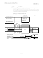
When writing in the initialization data before executing initialization, the initial data read
request (RY(N+1)9) turns ON, and the initialization data is written to the master station.
At this time, remote station ready (RX(n+1)B) turns OFF.
When the writing is completed, initial data read complete (RX(n+1)9) turns ON, and
the initial data read request (RY(n+1)9) turns OFF.
When these turn OFF, initial data read complete (RX(n+1)9) turns OFF, and remote
station ready (RX(n+1)B) turns ON.
RX(n+1)9
Initial data read
complete
Initial data read request (RY(n+1)9)
Initial data read complete
(RX(n+1)9)
Remote station ready (RX(n+1)B)
3-9
R2 writes initialization
data to master station.
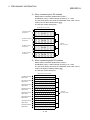
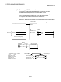
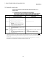
3 SPECIFICATIONS
Device No.
MELSEC-A
Signal name
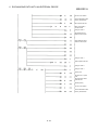
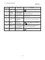
RX(n+1)A Error state
Details
This signal indicates the R2 error state.
If the R2 ERR.LED is lit, the error status (RX(n+1)A) turns ON, and when the
ERR.LED is OFF, the status turns OFF.
When an error occurs, the R2 stores the error code in the error code storage area
( R 2 1A8H to 1B2H).
When the error reset request (RY(n+1)A) is turned ON after remedying the error
cause, the error status (RX(n+1)A) can be turned OFF.
When the initialization error complete (RXn5) is ON, review the R2 initial setting and
turn ON the initialization request (RYn4) again to reinitialize the setting.
When the reinitialization is completed normally and the initialization normal complete
(RXn4) turns ON, the error state (RX(n+1)A) turns OFF.
(When the initialization error complete (RXn5) is ON, turning ON the error reset
request (RY(n+1)A) will not turn OFF the error state (RX(n+1)A).)
Error state (RX(n+1)A)
Any error cause
Error reset request (RY(n+1)A)
This signal indicates that the R2 can operate. (Refer to the section for RX(n+1)9.)
ON : The R2 is in the operatable state, and the initial data read request (RY(n+1)9)
RX(n+1)B Remote station ready
is OFF.
OFF : An R2 initialization error occurred (R2 buffer memory setting value error), or
when the initial data read request (RY(n+1)9) is turned ON.
Intelligent device
RX(n+1)E station access
complete
This signal indicates the R2 access complete state in response to the intelligent device
station access request (RY(n+1)E).
If not using dedicated commands and directly reading/writing from the programmable
controller CPU to the master station buffer memory, when accessing to the R2 is
completed, the R2 will turn intelligent device station access complete (RX(n+1)E) ON.
With this signal, the intelligent device station access request (RY(n+1)E) will turn OFF.
Intelligent device station
access request (RY(n+1)E)
Intelligent device station
access complete (RX(n+1)E)
3 - 10
Access to the intelligent
device station
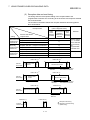
3 SPECIFICATIONS
MELSEC-A
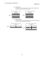
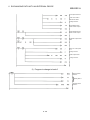
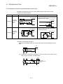
(2) Remote output (RY)
Device No.
RYn0
Signal name
Details
Transmission request Refer to the sections on RXn0 and RXn1.
To cancel the transmission after requesting transmission from R2, the transmission
will be canceled when the transmission cancel request (RYn1) turns ON.
When the transmission is forcibly canceled, the transmission normal complete (RXn0)
or transmission error complete (RXn1) will turn ON.
When these turn ON, the transmission request (RYn0) and transmission cancel
request (RYn1) will turn OFF.
RYn1
Transmission cancel
request
Transmission request (RYn0)
R2 is transmitting
contents of transmission
area to external device.
Transmission normal complete
(RXn0)
or Transmission error complete
(RXn1)
Forcibly cancels transmission.
Transmission cancel request
(RYn1)
RYn2
Reception read
complete
Refer to the sections on RXn2 and RXn3.
When the forced reception complete request (RYn3) turns ON, reception from the
external device will be forcibly completed.
When the forced reception is completed, the reception normal read request (RXn2)
and reception error read request (RXn3) will turn ON.
When these turn ON, forced reception complete request (RYn3) will turn OFF and
reception read complete (RYn2) will turn ON.
When the reception read complete (RYn2) turns ON, the reception normal read
request (RXn2) and reception error read request (RXn3) will turn OFF.
When this turns OFF, reception read complete (RYn2) will turn OFF.
RYn3
Forced reception
complete request
Forced reception complete
request
(RYn3) Forcibly completes
Reception normal read request
(RXn2)
or Reception error read request
(RXn3)
the reception.
Receiving data
Reception read complete (RYn2)
Reads reception area with program.
RYn4
Initialization request
Refer to the sections on RXn4 and RXn5.
RYn6
OS reception area
clear request
Refer to the section on RXn6.
RYn7
EEPROM function
request
Refer to the sections on RXn7 and RXn8.
3 - 11
3 SPECIFICATIONS
Device No.
Signal name
RS(RTS)
signal *1
RYn9
Signal
setting
RYnA
RYnC
RYnD
RY(n+1)9
MELSEC-A
ER(DTR)
signal *2
Details
This signal turns the RS (RTS) signal of the RS-232-C line ON or OFF.
Note that when "RS (RTS) signal status designation ( R 2 101H)" is set to "Always ON
(0)", the signal will remain ON even if the RS signal setting (RYn9) is turned ON or
OFF.
When controlling the RS signal with the RS (RTS) signal, set the above buffer memory
to "Follow RYn9 ON/OFF (1)".
This signal turns the ER (DTR) signal of the RS-232-C line ON or OFF.
When using DTR/DSR (ER/DR) control, even if the ER (DTR) signal (RYnA) is turned
ON or OFF, the process will follow the flow control designation ( R 2 100H) setting.
If the ER signal is being controlled with the ER (DTR) signal (RYnA) set the above
buffer memory to "No flow control (0)" or "Executing flow control by the DC code
control (2)".
This signal indicates the status of the R2 general-purpose output (YC, YD) with an ON
General-purpose
or OFF state.
external output signal
RYnC: Corresponds to YC
RYnD: Corresponds to YD
Initial data read
request
Refer to the section on RX(n+1)9.
RY(n+1)A Error reset request
Refer to the section on RX(n+1)A.
Intelligent device
RY(n+1)E station access
request
Refer to the section on RX(n+1)E.
3 - 12
3 SPECIFICATIONS
MELSEC-A
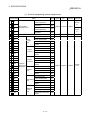
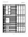
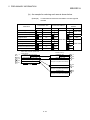
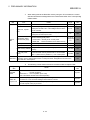
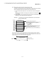
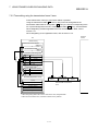
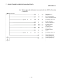
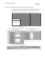
3.7 R2 buffer memory list
The entire configuration of the R2 buffer memory is explained in this section.
The contents of the R2 buffer memory are cleared to the default values when the
power is turned OFF.
However, if the user has registered the default values in the R2 EEPROM, the
EEPROM default values will be written in when the power is turned ON.
Refer to section 8.8 for details on writing to the R2 EEPROM.
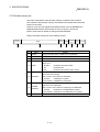
Refer to the buffer memory list in the following manner.
Address
Default
Initializavalue Update
tion
Name
(hexadecimal)
(1)
(2)
No.
(3)
Name
(4)
(5)
EEPROM
registra- Reference
tion
(6)
(7)
Details
(1) Address
Indicates R2 buffer memory address as a hexadecimal.
(2) Name
Indicates the name of the R2 buffer memory.
(3) Default value
Indicates the default value at R2 shipment.
Indicates whether the R2 buffer memory value is updated by the master
station or R2.
(4) Update
M station
: Updated by the master station
R2
: Updated by R2
Both
: Updated by both master station and R2
Indicates whether initialization is required when the R2 buffer memory
values have been changed.
(5) Initialization
Refer to section 8.6 for details on initialization.
Required
: Initialization is required.
Not required : Initialization is not required.
Indicates whether the contents of the R2 buffer memory can be
(6)
EEPROM
registration
registered in the R2 EEPROM.
Refer to section 8.8 for details on registering to the EEPROM.
Possible
: Registration to the EEPROM is possible.
Not possible : Registration to the EEPROM is not possible.
(7) Reference
Indicates the chapter, section or page containing detailed explanations.
3 - 13
3 SPECIFICATIONS
MELSEC-A
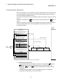
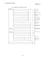
(1) Area for designating various assignments
Address
(hexadecimal)
Default
Update
value
Name
R 2 0H
Transmission area head
address designation
200H
R 2 1H
Transmission area size
designation
200H
Reception area head
address designation
400H
Reception area size
designation
200H
R 2 2H
Head address
designation area
R 2 3H
R 2 4H to FH System area (Use prohibited)
R 2 10H
R 2 11H
1A0H
(Fixed value: 4004H)
4004H
R 2 13H
Master station side offset
address
1A0H
R 2 14H
Transmission size
R 2 15H
R 2 17H
R 2 18H
Transmission size
R 2 19H
R 2 1AH
R 2 1CH
Automatic
update area
designation
R2 side head address
200H
Transmis4004H
sion area 2 (Fixed value: 4004H)
Master station side offset
200H
address
R2 side head address
400H
(Fixed value: 4004H)
4004H
R 2 1FH
Master station side offset
address
400H
R 2 20H
Transmission size
1A0H
R 2 21H
R2 side head address
R 2 22H
R 2 23H
Reception
area
0H
Initial setting
(Fixed value: 4004H)
4004H
area
Master station side offset
0H
address
R 2 24H
Transmission size
R 2 25H
R2 side head address
1C0H
(Fixed value: 4004H)
4004H
Master station side offset
address
1C0H
R 2 26H
R 2 27H
–
–
–
Possible
Section
5.6.2
200H
200H
R 2 1EH
–
88H
Transmission size
R 2 1DH
Section
6.2
R2 side head address
118H
Transmis4004H
sion area 1 (Fixed value: 4004H)
Master station side offset
118H
address
R 2 16H
R 2 1BH
Possible
20H
R2 side head address
Status
storage
area
R 2 12H
Section
6.1
M station Required
–
Transmission size
Initializa- EEPROM
Reference
tion
registration
EEPROM
function
area
3 - 14
30H
M station Required
3 SPECIFICATIONS
MELSEC-A
Address
(hexadecimal)
Default
Update
value
Name
R 2 28H
Transmission size
R 2 29H
R2 side head address
R 2 2AH
R 2 2BH
29H
1C7H
User
registration (Fixed value: 4004H)
4004H
frame area
Master station side offset
1C7H
address
R 2 2CH
Transmission size
88H
R 2 2DH
R2 side head address
118H
R 2 2EH
R 2 2FH
Automatic Monitor
update area transmis(Fixed value: 4004H)
4004H M station Required
designation sion area 1
Master station side offset
118H
address
R 2 30H
R 2 31H
R 2 32H
R 2 33H
R 2 34H to
Transmission size
R 2 40H
RW update interval time designation
1
R 2 41H
RWw update validity designation
0
R 2 42H
RWr update validity designation
–
–
Master station R2
(RWw0)
118H
R 2 44H
R2
(RWr0)
1B0H
R 2 45H
Master station R2
(RWw1)
119H M station Required
R 2 46H
(RWr1)
1B1H
(RWw2)
120H
R 2 48H
RW refresh
R 2 Master station
destination address
Master station R2
designation
R 2 Master station
(RWr2)
1B2H
R 2 49H
Master station R2
(RWw3)
121H
R 2 4AH
R2
(RWr3)
1B6H
Master station
Master station
System area (Use prohibited)
–
R 2 70H
Monitor interval time designation
0
R 2 71H
No. of monitor designation
0
System area (Use prohibited)
–
6FH
R 2 72H to
77H
R 2 78H
R 2 79H
R 2 7AH
R 2 7BH
Monitor
designation –1
Monitor
designation –2
Monitor target designation
0
Transmission data designation
0
Monitor target designation
0
Transmission data designation
0
R 2 7CH to
R 2 F7H
R 2 F8H to
FFH
–
Possible
Section
8.5
–
–
–
–
M station Required
Possible
Section
7.4
–
–
–
–
M station Required
Possible
Section
7.4
–
–
0
F5H
R 2 F6H
–
1
R 2 43H
R 2 4BH to
Section
5.6.2
R2 side head address
200H
Monitor
transmis(Fixed value: 4004H)
4004H
sion area 2
Master station side offset
200H
address
–
R 2 47H
Possible
200H
System area (Use prohibited)
3FH
Initializa- EEPROM
Reference
tion
registration
Monitor
designation –64
Monitor target designation
0
Transmission data designation
0
System area (Use prohibited)
–
3 - 15
–
–
3 SPECIFICATIONS
MELSEC-A
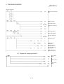
(2) Parameter area
Address
(hexadecimal)
Default
Update
value
Name
Initializa- EEPROM
Reference
tion
registration
R 2 100H
Flow control designation
1
Section
8.3
R 2 101H
RS (RTS) signal status designation
0
Section
8.9
R 2 102H
Word/byte unit designation
0
R 2 103H
ASCII-BIN conversion designation
0
Section
8.4
R 2 105H
Transient timeout time designation
0
Section
5.6.1
System area (Use prohibited)
–
R 2 106H to
107H
R 2 108H
R 2 109H
R 2 10AH
0
DH
Reception end frame No.
Reception head frame/reception end frame abort
designation
1
R 2 111H
Reception end data size designation
0
R 2 112H
Reception timeout time designation
0
System area (Use prohibited)
–
Transmission head frame No.
0
Transmission end frame No.
0
R 2 119H
Transmission
frame - 1 area
R 2 11AH
Transmission timeout time designation
0
System area (Use prohibited)
–
R 2 11BH to
11FH
R 2 120H
R 2 121H
R 2 122H
R 2 123H to
184H
Transmission table head No.
designation
0
No. of transmission tables
0
Transmission
frame - 2 area
No. 1
Transmission table
designation
R 2 185H
R 2 186H to
18FH
R 2 19DH to
19FH
Section
7.3
M station Required
Possible
0
R 2 110H
R 2 118H
–
0
R 2 10FH
R 2 113H to
–
0
AH
117H
–
Section
6.1, 6.2
0
Reception head frame No.
R 2 10CH
R 2 10EH
–
Possible
0
R 2 10BH
R 2 10DH
M station Required
Section
6.2
–
–
–
–
Section
7.2.1
Not
required
Possible
–
–
–
–
M station
Not
required
Possible
Section
7.2.2
M station
Section
6.1
0
No.100
System area (Use prohibited)
–
–
–
–
–
System area (Use prohibited)
–
–
–
–
–
3 - 16
3 SPECIFICATIONS
MELSEC-A
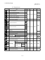
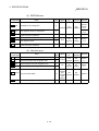
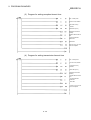
(3) Setting status storage area
Address
(hexadecimal)
Default
Update
value
Name
R 2 1A0H
Station No. setting switch
R 2 1A1H
Data link transmission speed setting switch
R 2 1A2H
Mode setting switch
R 2 1A3H
RS-232-C transmission speed
R 2 1A4H
RS-232-C data bit length
R 2 1A5H
RS-232-C parity bit presence
R 2 1A6H
RS-232-C stop bit length
R 2 1A7H
Buffer memory default value setting status storage
*1
R2
Initializa- EEPROM
Reference
tion
registration
Not
required
Not
possible
Section
8.10
Section
8.8
0
*1 Follows switch setting
(4) Communication status storage area
Address
(hexadecimal)
R 2 1A8H to
1AFH
R 2 1B0H
R 2 1B1H
R 2 1B2H
Default
value
Name
Error code
storage area
Error code history
0
General error code
0
Error code at transmission
0
Error code at reception
0
Update
Initializa- EEPROM
Reference
tion
registration
R2
Not
required
Not
possible
Section
10.1.1
–
–
–
–
R 2 1B3H
System area (Use prohibited)
–
R 2 1B4H
Actual transmission data size storage
0
R 2 1B5H
Reception frame index No. storage
0
R 2 1B6H
No. of data items in OS reception area data size
storage
0
System area (Use prohibited)
–
–
–
–
–
Follows
version
R2
Not
required
Not
possible
Section
8.10
R 2 1B7H to
1BEH
R 2 1BFH
Software version storage
3 - 17
Section
6.1
R2
Not
required
Not
possible
Section
7.3
Section
6.2
3 SPECIFICATIONS
MELSEC-A
(5) EEPROM area
Address
(hexadecimal)
R 2 1C0H
Default
value
Name
EEPROM function designation
Update
0
M station
R 2 1C1H
R 2 1C2H to
1C6H
R 2 1C7H
R 2 1C8H to
1EFH
R 2 1F0H to
1FFH
User-registered frame No. designation
0
System area (Use prohibited)
–
User-registered frame byte designation
0
User-registered frame
0
System area (Use prohibited)
–
Initializa- EEPROM
Reference
tion
registration
Not
required
Not
possible
Section
8.8 and
Section
7.5.2
Section
7.5.2
–
–
–
–
Both
Not
required
Not
possible
Section
7.5.2
–
–
–
–
(6) User free area
Address
(hexadecimal)
R 2 200H
R 2 201H to
3FFH
R 2 400H
R 2 401H to
5FFH
R 2 600H to
7FFH
R 2 800H to
F1FH
Default
Update
value
Name
Default transmission data size designation area
0
Default transmission data designation area
0
Default reception data size designation area
0
Default reception data designation area
0
Area not used at default
0
System area (Use prohibited)
–
3 - 18
Initializa- EEPROM
Reference
tion
registration
M station
Not
required
Not
possible
Section
6.1
R2
Not
required
Not
possible
Section
6.2
Follows
transmission/
Not
reception required
area
setting
Not
possible
Chapter 6
–
–
–
–
3 SPECIFICATIONS
MELSEC-A
3.8 Transmission delay time
The transmission delay time (time for data to be conveyed) is shown below.
(1) Calculation expressions
Calculation expression (unit: ms)
When the master
Details
When the master
station is the A/QnA
station is the Q Series
Series
Master station (RX/RWr)
Master station (RY/RWw)
Master station (RX)
R2 (RX/RWr)
R2 (RY/RWw)
G eneral-purpose input
G eneral-purpose output
SM + LS × 3 + 2
(RYnC, RYnD)
SM :
LS :
RS :
SM + LS × 2 + RS
SM + LS × 3 + 10
(RXnC, RXnD)
Master station
SM + LS × 3 + RS
SM + LS × 3 + RS
Master station sequence program's scan time
Link scan time (Refer to Master Module User's Manual)
R2 internal processing time *1
*1 R2 internal processing time
The R2 internal processing time is calculated with the following equation.
R2 internal processing time (R2) = LS × K (constant)
Transmission
speed
K (constant)
156kbps
625kbps
2.5Mbps
5Mbps
10Mbps
2
2
4
8
32
(2) Calculation example
An example for calculating the transmission delay time from the master station
(RX/RWr) to R2 (RX/RWr).
When only one R2 is connected with SM: 20ms, and transmission speed:
156kbps
(a) When the master station is the A/QnA Series
LS : 51.2 {29.4 + (8 × 4.8) + (8 × 9.6) + (1 + 32.4) + (1 × 4.8) + (1 × 9.6)} +
1300 = 11100µs (11.1ms)
20 + 11.1 × 3 + 11.1 × 2 = 75.5ms
(b) When the master station is the Q Series
LS : 51.2 {27 + (8 × 4.8) + (8 × 9.6) + (1 × 30) + (1 × 4.8) + (1 × 9.6)} +
1300 + 0 + 0 = 10854µs (10.9ms)
20 + 10.9 × 2 + 10.9 × 2 = 63.6ms
3 - 19
3 SPECIFICATIONS
MELSEC-A
3.9 Transmission/reception time
The transmission/reception time is shown below.
3.9.1 When using buffer memory automatic update function
The transmission time is the time from when the transmission request (RYn0) turns ON
to when the R2 turns the transmission normal complete (RXn0) ON.
The reception time is the time from when the R2 starts receiving the data to when the
reception normal read request (RXn2) and reception error read request (RXn3) are
turned ON by the R2.
(1) Calculation expressions
Details
Calculation expression (unit: ms)
SM × 2 + LS × 6 + RS + data transmission time *1 + request/response
When the master station
is the A/QnA Series
Transmission time
scan time of area to be updated at transmission *2
SM + LS × 3 + RS + data reception time *1 + request/response scan
Reception time
time of area to be updated at reception *2
SM × 2 + LS × 4 + RS + data transmission time *1 + request/response
When the master station
is the Q Series
Transmission time
scan time of area to be updated at transmission *2
SM + LS × 2 + RS + data reception time *1 + request/response scan
Reception time
SM :
LS :
RS :
time of area to be updated at reception *2
Master station sequence program's scan time
Link scan time (Refer to Master Module User's Manual.)
R2 internal processing time (Refer to section 3.8 (1).)
*1 Data transmission (reception) time
This time is obtained with the data size and RS-232-C transmission speed.
(Example) Data size: 200 bytes, Transmission speed: 9600bps (data bit length:
8, stop bit length: 1, parity bit: even)
200 × 10/9600 = 0.208s
*2 Request/response scan of area to be updated at transmission (reception)
This is the response/request scan of each area automatically updated during
transmission (reception).
With the default value for transmission, the status storage area and transmission
area 1 and 2 are updated. With the reception default value, the status storage
area and reception area are updated.
<Request/response scan of area where data is written from master station to R2>
(Size of data to be automatically updated + 16)/72 × LS [ms]
Decimal point rounded up
<Request/response scan of area where data is written from R2 to master station>
(Size of data to be automatically updated + 16)/16 × LS [ms]
Decimal point rounded up
3 - 20
3 SPECIFICATIONS
MELSEC-A
(2) Calculation example
(a) Transmission time
An example of calculating the transmission time for transmitting 10 words
(20 bytes) of data is shown below.
Item
Setting details
Transmission size of each area
Default value
Transmission speed
156kbps
No. of connected modules
Only one R2 module
Master station sequence program scan time
20ms (Hypothetical)
Transmission speed
9600bps
Data bit length
8
Stop bit length
1
Parity bit
Even
1) When the master station is the A/QnA series
LS = 51.2 {29.4 + (8 × 4.8) + (8 × 9.6) + (1 × 32.4) + (1 × 4.8) + (1 × 9.6)}
+ 1300 = 11100µs (11.1ms)
Data transmission time = 20 × 10/9600 = 0.0208s (20.8ms)
Transmission time = 20 × 2 + 11.1 × 6 + (11.1 × 2) *1 + 20.8 *2
+ {(136 + 16)/72 × 11.1} *3 + {(512 + 16)/72 × 11.1} *4
+ {(32 + 16)/16 × 11.1} *5
= 149.6 + 3 × 11.1 + 8 × 11.1 + 3 × 11.1
= 305ms
2) When the master station is the Q series
LS = 51.2 {27 + (8 × 4.8) + (8 × 9.6) + (1 × 30) + (1 × 4.8) + (1 × 9.6)}
+ 1300 +0 +0 = 10854µs (10.9ms)
Data transmission time = 20 × 10/9600 = 0.0208s (20.8ms)
Transmission time = 20 × 2 + 10.9 × 4 + (10.9 × 2) *1 + 20.8 *2
+ {(136 + 16)/72 × 10.9} *3 + {(512 + 16)/72 × 10.9} *4
+ {(32 + 16)/16 × 10.9} *5
= 126.2 + 3 × 10.9 + 8 × 10.9 + 3 × 10.9
= 278.8ms
*1
*2
*3
R2 (R2 internal processing time)
Data transmission time
Transmission area 1 request/response scan (88H (136 words)
*4
worth)
Transmission area 2 request/response scan (200H (512 words)
*5
worth)
Status storage area request/response scan (20H (32 words)
worth)
3 - 21
3 SPECIFICATIONS
MELSEC-A
(b) Reception time
An example for calculating the reception time when receiving 10 words (20
bytes) of data is shown below.
Item
Setting details
Transmission size of each area
Default value
Transmission speed
156kbps
No. of connected modules
Only one R2 module
Master station sequence program scan time
20ms (Hypothetical)
Transmission speed
9600bps
Data bit length
8
Stop bit length
1
Parity bit
Even
1) When the master station is the A/QnA series
LS = 51.2 {29.4 + (8 × 4.8) + (8 × 9.6) + (1 × 32.4) + (1 × 4.8) + (1 × 9.6)}
+ 1300 = 11100µs (11.1ms)
Data reception time = 20 × 10/9600 = 0.0208s (20.8ms)
Reception time
= 20 + 11.1 × 3 + (11.1 × 2) *1 + 20.8 *2
+ {(32 + 16)/16 × 11.1} *3 + {(512 + 16)/16 × 11.1} *4
= 96.3 + 3 × 11.1 + 33 × 11.1 = 495.9ms
2) When the master station is the Q series
LS = 51.2 {27 + (8 × 4.8) + (8 × 9.6) + (1 × 30) + (1 × 4.8) + (1 × 9.6)}
+ 1300 + 0 + 0 = 10854µs (10.9ms)
Data reception time = 20 × 10/9600 = 0.0208s (20.8ms)
Reception time
= 20 + 10.9 × 2 + (10.9 × 2) *1 + 20.8 *2
+ {(32 + 16)/16 × 10.9} *3 + {(512 + 16)/16 × 10.9} *4
= 84.4 + 3 × 10.9 + 33 × 10.9 = 476.8ms
*1 RS (R2 internal processing time)
*2 Data transmission time
*3 Status storage area request/response scan (20H (32 words)
worth)
*4 Reception area request/response scan (200H (512 words)
worth)
3 - 22
3 SPECIFICATIONS
MELSEC-A
3.9.2 When using transmission/reception buffer
The transmission time is the time from when the transmission data is stored in the R2,
the transmission request (RYn0) is turned ON to when the transmission normal
complete (RXn0) is turned ON by the R2.
The reception time is the time from when the R2 starts receiving the data, the reception
normal read request (RXn2) and reception error read request (RXn3) are turned ON by
the R2, to when the data is received.
(1) Calculation expression
Details
Calculation expression (unit: ms)
SM + 2 + LS × 6 + RS + data transmission time *1 + transient
When the master station
is the A/QnA Series
Transmission time
transmission time*2
SM + LS × 3 + RS + data reception time *1 + transient transmission
Reception time
time*2
SM + 2 + LS × 4 + RS + data transmission time *1 + transient
When the master station
is the Q Series
Transmission time
transmission time*2
SM + LS × 2 + RS + data reception time *1 + transient transmission
Reception time
SM :
LS :
RS :
time*2
Master station sequence program's scan time
Link scan time (Refer to Master Module User's Manual)
R2 internal processing time (Refer to section 3.8 (1))
*1
Data transmission (reception) time
This time is obtained with the data size and RS-232-C transmission speed.
(Example) Data size: 200 bytes, transmission speed: 9600bps (data bit length:
8, stop bit length: 1, parity bit: even)
200 × 10/9600 = 0.208s
*2
Transient transmission time
During transmission, this is the time for the data to be written from the master
station to the R2.
During reception, this is the time for reading the data from the R2 to the master
station.
Refer to section 5.4.3 in the Q Series Master Module User's Manual for the
calculation expressions.
3 - 23
3 SPECIFICATIONS
MELSEC-A
(2) Calculation example
(a) Transmission time
An example of calculating the transmission time for transmitting 10 words
(20 bytes) of data is shown below.
Item
Setting details
Transmission speed
156kbps
No. of connected modules
Only one R2 module
Master station sequence program scan time
20ms (Hypothetical)
Transmission speed
9600bps
Data bit length
8
Stop bit length
1
Parity bit
Even
1) When the master station is the A/QnA series
LS = 51.2 {29.4 + (8 × 4.8) + (8 × 9.6) + (1 × 32.4) + (1 × 4.8) + (1 × 9.6)}
+ 1300 = 11100µs (11.1ms)
Data transmission time = 20 × 10/9600 = 0.0208s (20.8ms)
Transmission time = 20 × 2 + 11.1 × 6 + (11.1 × 2) *1 + 20.8 *2
+ {20 + 11.1 + (11 + 16)/72 × 11.1 + 11.1 + 20
+ 11.1 × 2 + 11.1 + 11.1 + 11.1} × 1 *3
= 149.6 + (20 + 11.1 + 11.1 + 11.1 + 20 + 22.2 + 11.1
+ 11.1 + 11.1)
= 149.6 + 128.8
= 278.4ms
2) When the master station is the Q series
LS = 51.2 {27 + (8 × 4.8) + (8 × 9.6) + (1 × 30) + (1 × 4.8) + (1 × 9.6)}
+ 1300 + 0 + 0 = 10854µs (10.9 ms)
Data transmission time = 20 × 10/9600 = 0.0208s (20.8ms)
Transmission time = 20 × 2 + 10.9 × 4 + (10.9 × 2) *1 + 20.8 *2
+ 1 + 10.9 × [ 6 + {(11 + 16) / 72} × 1.13] *3
= 126.2 + 78.717
= 204.917
= 205.0ms
*1 R2 (R2 internal processing time)
*2 Data transmission time
*3 Transient transmission time (10 words + 1 word (transmission
data size) worth)
3 - 24
3 SPECIFICATIONS
MELSEC-A
(b) Reception time
An example for calculating the reception time when receiving 10 words (20
bytes) of data is shown below.
Item
Setting details
Transmission speed
156kbps
No. of connected modules
Only one R2 module
Master station sequence program scan time
20ms (Hypothetical)
Transmission speed
9600bps
Data bit length
8
Stop bit length
1
Parity bit
Even
1) When the master station is the A/QnA series
LS = 51.2 {29.4 + (8 × 4.8) + (8 × 9.6) + (1 × 32.4) + (1 × 4.8) + (1 × 9.6)}
+ 1300 = 11100µs (11.1ms)
Data reception time = 20 × 10/9600 = 0.0208s (20.8ms)
Reception time
= 20 + 11.1 × 3 + (11.1 × 2) *1 + 20.8 *2
+ {20 + 11.1 + 11.1 + 11.1 + 20 + 11.1 × 2 + (10
+ 16)/16 × 11.1 + 11.1 + 11.1} × 1 *3
= 96.3 + (20 + 11.1 + 11.1 + 11.1 + 20 + 22.2 + 11.1
+ 11.1)
= 96.3 + 139.9
= 236.2ms
2) When the master station is the Q series
LS = 51.2 {27 + (8 × 4.8) + (8 × 9.6) + (1 × 30) + (1 × 4.8) + (1 × 9.6)}
+ 1300 + 0 + 0 = 10854µs (10.9 ms)
Data transmission time = 20 × 10/9600 = 0.0208s (20.8ms)
Transmission time = 20 × 2 + 10.9 × 2 + (10.9 × 2) *1 + 20.8 *2
+ 1 + 10.9 × [ 6 + {(10 + 16) / 16} × 1.067] *3
= 84.4 + 89.6606
= 174.0606
= 174.1ms
*1 R2 (R2 internal processing time)
*2 Data transmission time
*3 Transient transmission time (10 words worth)
3 - 25
3 SPECIFICATIONS
MELSEC-A
MEMO
3 - 26
4 PROCEDURES AND SETTINGS BEFORE OPERATION
MELSEC-A
4. PROCEDURES AND SETTINGS BEFORE OPERATION
The operation procedures before starting the R2 operation, names and settings of
each R2 section, wiring method and hardware test are described in this section.
4.1 Procedures before operation
The procedures before operating the R2 are explained below.
Start
Test the R2 hardware.
Refer to section 4.6.
Hardware test normal
4
Test the master module hardware.
Hardware test normal
Connect the master module and module, such as the R2, with a CC-Link
dedicated cable.
Connect the R2 and external device with an RS-232-C cable.
Set each switch on the master module.
* When using the AJ61BT11 or A1SJ61BT11, set SW8 of the condition setting
switch OFF (intelligent mode).
Set each switch on the R2.
Refer to section 4.5.
Refer to master module manual.
Refer to section 4.4.
Turn the power ON in the order of the external device, R2 and master module.
Test the data link line with the master module.
Refer to master module manual.
Line test normal
(Continued on next page)
4-1
4 PROCEDURES AND SETTINGS BEFORE OPERATION
(Continued from previous page)
Create a program.
1. Initializing the master module
2. Reading the remote input (RX)
3. Confirming the R2 data link state
4. Initializing the R2
5. Transmitting data to the external device
6. Exchanging data with the external device
7. Processing R2 errors
8. Writing in the remote output (RY)
Start the data link.
Completed.
4-2
(Refer to Section 5.4.)
(Refer to Section 5.3 (2).)
(Refer to Section 5.3 (3).)
(Refer to Section 5.5.)
(Refer to Section 6.3.1, 6.4.1.)
(Refer to Section 6.3.2, 6.4.2.)
(Refer to Section 5.3 (7).)
(Refer to Section 5.3 (8).)
MELSEC-A
4 PROCEDURES AND SETTINGS BEFORE OPERATION
MELSEC-A
4.2 Precautions for handling
The precautions for handling the R2 are shown below.
DANGER
• Do not touch the terminals or connectors while the power is ON.
Failure to observe this could lead to electric shocks or malfunctioning.
• Do not touch the connector inside the lid at the top of the module.
Failure to observe this could lead to module trouble or malfunctioning.
CAUTION
• Make sure that foreign matter, such as cutting chips or wire scraps, do not enter the
module.
Failure to observe this could lead to fires, trouble or malfunctioning.
• Never disassemble or modify the module.
Failure to observe this could lead to trouble, malfunctioning, injuries or fires.
• The module case is made of resin, so do not drop it or apply strong impacts on it.
Failure to observe this could lead to module damage.
• Tighten the terminal screws within the specified torque range.
A loose terminal screw could lead to short-circuiting or malfunctioning.
If the terminal screw is too tight, short-circuiting or malfunctioning could occur due to
screw damage.
• Dispose of this product as industrial waste.
• Use this module within the general specification environment described in the
manual.
Use in an environment outside the general specification range could lead to electric
shocks, fires, malfunctioning, product damage or deterioration.
• Securely fix the module with the DIN rail or installation screw. Tighten the installation
screw within the designated torque range.
A loose screw could lead to dropping, short-circuiting or malfunctioning.
If the screw is too tight, dropping or short-circuiting could occur due to screw
damage.
• Before installing or removing the module on the panel, be sure to shut off all phases
of external power supply used by the system.
Failure to shut off all phases could lead to module trouble or malfunctioning.
4-3
4 PROCEDURES AND SETTINGS BEFORE OPERATION
MELSEC-A
(1) Tighten the module installation screws and terminal block screws
within the following range.
Screw place
Tightening torque range
Remarks
Module installation screw (M4 screw)
0.78 to 1.18N⋅ m
-
Terminal block terminal screw (M3.5 screw)
0.59 to 0.88N⋅ m
-
Terminal block installation screw (M4 screw)
0.98 to 1.37N⋅ m
-
RS-232-C cable connector screw (M2.6 screw)
0.20 to 0.39N⋅ m
Screw hole depth: L=3.2mm or less
(Internal dimension from end face)
(2) When using the DIN rail adaptor, install the DIN rail while observing
the following points.
(a) Applicable DIN rail type (JIS C 2812 compliant)
TH35-7.5Fe
TH35-7.5Al
TH35-15Fe
(b) DIN rail installation screw pitch
When installing the DIN rail, tighten the screws at a pitch of 200mm or less.
4-4
4 PROCEDURES AND SETTINGS BEFORE OPERATION
MELSEC-A
4.3 Installation environment
When installing the programmable controller, refer to the CC-Link system master
module's User's Manual.
4-5
4 PROCEDURES AND SETTINGS BEFORE OPERATION
MELSEC-A
4.4 Names of each part, and settings
The names of the parts in the R2, the LED details, and the settings for each switch are
explained in this section.
(10)
(1)
(4)
(3)
(2)
(9)
(5)
(6)
No.
(7)
Name
(1) Operation display LEDs
(8)
Details
LED name
PW
Default
state
State
Others
ON: Power is ON.
Details
OFF: Power is OFF.
OFF: Power (24VDC) is OFF, WDT error is occurring or
the switch setting is incorrect.
ON: Communicating normally OFF: Communication stopped (Time over error) or the
L RUN
switch setting is incorrect.
ON: Any transmission speed or station number out of range is set.
Flickering at constant intervals : The transmission speed or station number has been
changed after the power is turned on.
L ERR.
Flickering not constant intervals : The terminating resistor is not connected. The module or
CC-Link dedicated cable is being affected by noise.
OFF: Communicating normally
SD
ON, Flashing: Data link Sending data
OFF: Data link Not sending data
RUN
RD
XC, XD
YC, YD
RS-232-C SD
RS-232-C RD
RS-232-C
ERR.
ON: Operating normally
ON, Flashing: Data link Receiving data
OFF: Data link Not receiving data
ON: General-purpose input (XC, XD) is ON.
OFF: General-purpose input (XC, XD) is OFF.
ON: General-purpose output (YC, YD) is ON.
OFF: General-purpose output (YC, YD) is OFF.
ON, Flashing: Sending RS-232-C data
OFF: Not sending RS-232-C data
ON, Flashing: Receiving RS-232-C data
OFF: Not receiving RS-232-C data
ON: RS-232-C transmission error
4-6
OFF: No error
4 PROCEDURES AND SETTINGS BEFORE OPERATION
No.
Name
(2) Station No. setting switch
MELSEC-A
Details
Set the module's station No. (Default setting: 0)
Setting range: 1 to 64 (0: Master module)
" 10" sets the 10th place of the station No..
" 1" sets the 1st place of the station No..
(3) Data link transmission speed
Setting
Transmission speed
0
156kbps
1
625kbps
2
2.5Mbps
setting switch
(4) Mode setting switch
3
5Mbps
4
10Mbps
-
Setting error
Set the module's transmission speed (for data
link)
(Default setting: 0)
Set the module's operation state. (Default setting: 0)
No.
Name
On-line mode (using
transmission/reception buffer)
On-line mode (using buffer memory
1
automatic update function)
2 Not used
Setting details
Mode for on-line communication.
Set when using the transmission/reception buffer.
Mode for on-line communication.
Set when using the buffer memory automatic update function.
Setting error ("RUN" LED turns OFF.)
3 Not used
Setting error ("RUN" LED turns OFF.)
0
4 Use not possible
(5) RS-232-C transmission
specifications setting switch
–
5 Not used
Setting error ("RUN" LED turns OFF.)
6 Not used
Setting error ("RUN" LED turns OFF.)
7 Not used
Setting error ("RUN" LED turns OFF.)
8 Not used
Setting error ("RUN" LED turns OFF.)
9 Not used
Setting error ("RUN" LED turns OFF.)
A Not used
Setting error ("RUN" LED turns OFF.)
B Not used
Setting error ("RUN" LED turns OFF.)
C Not used
Setting error ("RUN" LED turns OFF.)
D Hardware test mode
Mode for confirming that module runs independently.
E Not used
Setting error ("RUN" LED turns OFF.)
F Not used
Setting error ("RUN" LED turns OFF.)
Set the RS-232-C transmission specifications.
No.
Setting switch state
Setting details
ON
SW
SW1 to 3 Transmission speed
SW4
SW5
SW6
SW7
SW8
(6) Data link terminal block
1
0
1
0
1
0
1
0
Not used
8
Yes
Even
2
Data bit length
Parity bit
Stop bit length
2
0
0
1
1
0
0
1
0:OFF 1:ON
3
0
0
0
0
1
1
1
300bps
600bps
1200bps
2400bps
4800bps
9600bps
19200bps
7
No
Odd
1
OFF
ON
OFF
Connect a CC-Link dedicated cable for power supply and data link. (2-piece terminal
block)
(7) RS-232-C interface
Default
setting
OFF
Connect an RS-232-C cable for connection with external device.
(8) General-purpose input/output Connect the input/output wire.
terminal block.
(9) Reset switch
Returns to the power ON status.
(10) Connector
Use prohibited.
4-7
4 PROCEDURES AND SETTINGS BEFORE OPERATION
MELSEC-A
4.5 Wiring
4.5.1 Precautions for handling the CC-Link dedicated cables
Avoid the following extreme handling. Such handling will damage the CC-Link
dedicated cables.
• Compress the cable with a sharp edge.
• Twist the cable extremely.
• Pull the cable extremely hard. (More than permissible tension)
• Step on the cable.
• Put an object on the cable.
• Scratch the cable sheath.
4.5.2 Connection of the CC-Link dedicated cables
CAUTION
• Before starting installation or wiring work, be sure to shut off all phases of external
power supply used by the system. Failure to shut off all phases could lead to electric
shocks, product damage or malfunctioning.
• Always install the terminal covers enclosed with the product before turning ON the
power or operating the product after installation or wiring work.
Failure to install the terminal cover could lead to electric shocks.
• Before cleaning or tightening the terminal screws, be sure to shut off all phases of
external power supply used by the system. Failure to shut off all phases could lead
to module trouble or malfunctioning. A loose screw could lead to dropping, shortcircuiting or malfunctioning. If the screw is too tight, dropping or short-circuiting
malfunctioning could occur due to screw damage.
• Do not bind the control wire or communication cable with the main circuit or power
wire, or place the control wire near these. Separate by at least 100mm or more.
Failure to observe this could lead to malfunctions caused by noise.
• Always ground the FG terminal with Class D grounding (grounding resistance :
100Ω or less) or higher dedicated of the programmable controller.
Failure to do so could lead to electric shock or malfunctioning.
• Always confirm the product's rated voltage and terminal layout before wiring the
module. Connecting with a power supply other than the rated power supply, or
incorrect wiring could lead to fires or trouble.
• Securely mount the connector of each connection cable to the mounting section.
An incomplete connection could lead to malfunctioning causes.
• Be sure to fix the wires or cables by ducts or clamps when connecting them to the
module. Failure to do so may cause damage of the module or the cables due to
accidental pull or unintentional shifting of the cables, or malfunctions due to poor
contact of the cable.
• Do not install the control lines together with the communication cables, or bring them
close to each other. Failure to do so may cause malfunctions due to noise.
• Always connect the master module and CC-Link dedicated cable at the data link
terminal block. If the data link terminal block and general-purpose output terminal
block are incorrectly inserted, module trouble could occur.
Data link terminal block
4-8
General-purpose input/
output terminal block
4 PROCEDURES AND SETTINGS BEFORE OPERATION
MELSEC-A
The method of connecting the R2, master module and remote module with a CC-Link
dedicated cable is shown below.
Master module
DA
Terminator
DB
DG
(B)
(W)
(Y)
SLD
FG
R2
Remote module
DA
DA
DB
DB
DG
CC-Link dedicated
cable
SLD
24V
Terminator
DG
CC-Link dedicated
cable
SLD
24V
24G
24G
FG
FG
POINT
Always connect the modules on both ends of the data link with the "terminator"
enclosed with the master module. (Connect across DA-DB)
4.5.3 Connection with external device
The method of connecting the R2 and external device with RS-232-C is show below.
(1) Example of connection for DC code control and DTR/DSR signal
control
R2 side (DTE)
Cable connection and signal method
External device (DTE)
Signal abbrev.
Pin No.
Signal abbrev.
SD
3
SD
RD
2
RD
RS
7
RS
CS
8
CS
DR
6
DR
SG
5
SG
CD
1
CD
ER
4
ER
(2) Example of connection for only DC code control
R2 side (DTE)
Signal abbrev.
Pin No.
Cable connection and signal method
External device (DTE)
Signal abbrev.
SD
3
SD
RD
2
RD
RS
7
RS
CS
8
CS
DR
6
DR
SG
5
SG
CD
1
CD
ER
4
ER
4-9
4 PROCEDURES AND SETTINGS BEFORE OPERATION
MELSEC-A
(3) Precautions for connections
(a)
R2 does not use the CD signal as a control signal in sending/receiving data
to/from an external device.
(b)
Handle the connection cable's FG signal and shield as described below.
Connection method
FG signal Connect to the body of the
Shield
(c)
Remarks
Do not short circuit the FG signal and
R2 connector.
SG signal of the connection cable.
Connect to the body of the
When the FG signal and SG signal are
R2 connector.
connected internally on the external
(Do not connect with the
device side, do not connect the R2 side
external device.)
FG signal with the external device.
If the data cannot be communicated due to noise from the external device,
even when the above wiring and connection are used, wire and connect as
shown below.
1)
Connect across the FG of each station with the connection cable's
shield.
For an external device, connect as explained in the instruction manual
for the external device.
2)
Connect the signals other than the connection cable's SG and FG as a
pair with SG.
(R2 side)
Shield
(Partner device side)
FG
Connector body section
SD
RD
RD
SD
DSR
SG
.....
DTR
.....
DTR
.....
DSR
SG
* The R2 FG is connected with the screw fixing section of the connector, and
is the FG for the module body.
(d)
Do not connect the RS-232-C interface with an RS-422 device.
If connected with an RS-422 device, the hardware of the connected
devices's RS-422 interface could be damaged and communication
inhibited.
4 - 10
4 PROCEDURES AND SETTINGS BEFORE OPERATION
MELSEC-A
4.6 Checking the module's state (Hardware test)
Confirm that the R2 operates normally as a single module. Always carry out this test
before structuring the system.
Execute the test with the following procedure.
Start
Disconnect the CC-Link dedicated cable for
the data link from R2.
Mount an RS-232-C single module loopback connector.*1
Set the data link related hardware.
· Set the data link transmission speed setting switch.
Set the mode setting switch to "D".
(hardware test mode)
Turn ON the R2 power.
Confirm the RS-232-C ERR. LED *2
*1
The specifications of the RS-232-C single module loopback connector are shown
below.
Create the RS-232-C single module loopback connector shown below.
R2 side (DTE)
Single module loopback
Signal abbrev.
Pin No.
CD
1
RD (RXD)
2
SD (TXD)
3
DTR (ER)
4
SG
5
DSR (DR)
6
RS (RTS)
7
CS (CTS)
8
–
9
connector
IMPORTANT
During the hardware test mode, the check data is transmitted to the data link when
checking the data link loopback, so always disconnect the data link wiring.
4 - 11
4 PROCEDURES AND SETTINGS BEFORE OPERATION
*2
When normal
:
When abnormal :
LED state
MELSEC-A
The RS-232-C ERR.LED flickers.
The state is normal if the LED flickers for 30 seconds or
more.
The RS-232-C ERR.LED turns ON.
The error cause is indicated with the YC LED and YD LED
states.
Details
Measures
ROM check error
The hardware may be faulty, so contact your
nearest dealer or Mitsubishi branch.
RAM check error
Disconnect the CC-Link dedicated cable.
Hardware error, or CC-Link dedicated
cable is still connected.
If the ERR.LED does not flicker even when the
CC-Link dedicated cable is disconnected, the
hardware may be faulty, so contact your
nearest dealer or Mitsubishi branch.
Mount the loopback counter.
Hardware error, or RS-232-C loopback
connector is not connected.
If the ERR.LED does not flicker even when
loopback connector is connected, the hardware
may be faulty, so contact your nearest dealer or
Mitsubishi branch.
: OFF,
: ON
4 - 12
5 PRELIMINARY INFORMATION
MELSEC-A
5. PRELIMINARY INFORMATION
5.1 System used in this manual
An example of the sequence program explained in this manual is described for the
following system.
Refer to the CC-Link Master Module User's Manual (Details) for details on the
sequence program for the entire CC-Link system.
(1) System configuration for program example
Programmable controller CPU
Master station (X0 to X1F/Y0 to Y1F)
5
R2 (Station No. 1)
(2) Relation of programmable controller CPU, master station and R2
The contents of RXn0 to RX(n+1)F are read to X100 to X11F, and the contents
of Y100 to Y11F are written into RYn0 to RY(n+1)F and used.
Master station
Programmable controler CPU
R2
Device X
Address
Remote input (RX)
Remote input (RX)
X100 to X10F
E0H
RXn0 to RXnF
RXn0 to RXnF
X110 to X11F
E1H
RX(n+1)0 to RX(n+1)F
RX(n+1)0 to RX(n+1)F
Remote output (RY)
Device Y
Remote output (RY)
Y100 to Y10F
160H
RYn0 to RYnF
RYn0 to RYnF
Y110 to Y11F
161H
RY(n+1)0 to RY(n+1)F
RY(n+1)0 to RY(n+1)F
5-1
5 PRELIMINARY INFORMATION
MELSEC-A
(3) Master station buffer memory settings (buffer memory size)
Transmission buffer
Reception buffer
Automatic update
buffer
0H
0H
600H
200H
200H
0H
When using the buffer memory
automatic update function
When using the
transmission/reception buffer
(4) R2 buffer memory setting
The R2 buffer memory is used with the factory-set state (default values).
5-2
5 PRELIMINARY INFORMATION
MELSEC-A
5.2 Programming Precautions
5.2.1 About bank changing of the A series master module
When using the R2, the master station's automatic update buffer or
transmission/reception buffer is used.
With the A Series master module (AJ61BT11/A1SJ61BT11), the automatic update
buffer and transmission/reception buffer are divided with banks. When accessing these
buffers, the bank must be changed.
POINT
•
•
When using dedicated commands (RITO, RIFR, RIRD, RIWT, RISEND,
RIRCV), the bank is changed with the dedicated commands, and does not need
to be changed by the user.
After changing to bank 1 or bank 2 and then reading or writing, return to bank 0.
The information such as RX, RY, RWw or RWr will not be updated unless the
bank is changed to bank 0.
A Series master module buffer memory (AJ61BT11/A1SJ61BT11)
Bank 0
M 0H
Parameter, status
information, etc.
M FFFH
Bank 1
M 0H
Bank 2
M 0H
Intelligent device
station transmission
/reception buffer
M FFFH
M FFFH
Intelligent device
station automatic
update buffer
Q/QnA Series master module buffer memory
(AJ61QBT11/A1SJ61QBT11/QJ61BT11/QJ61BT11N)
M 0H
M FFFH
Parameter, status
information, etc.
M 1000H
Intelligent device
station transmission
M 1FFFH /reception buffer
M 2000H
M 2FFFH
Intelligent device
station automatic
update buffer
(1) Changing the bank
The bank can be changed by turning the master module's Y(n+1)C, Y(n+1)D ON
and OFF.
n indicates the master module's head input/output No.
Y (n+1) C
Y (n+1) D
Details
OFF
OFF
Change to bank 0
ON
OFF
Change to bank 1
OFF
ON
Change to bank 2
5-3
5 PRELIMINARY INFORMATION
MELSEC-A
(2) Program
Create the program for changing the bank as shown below.
Refer to section 5.1 for details on the program conditions.
(a) Program for changing to bank 0
Changeover execution
Specify partial
refresh
Specify bank 0
Execute partial
refresh
(b) Program for changing to bank 1
Changeover execution
Specify partial
refresh
Specify bank 1
Execute partial
refresh
(c) Program for changing to bank 2
Changeover execution
Specify partial
refresh
Specify bank 2
Execute partial
refresh
5-4
5 PRELIMINARY INFORMATION
MELSEC-A
5.2.2 About dedicated commands for use of the buffer memory automatic update function
When the buffer memory automatic update function is used, the R2 buffer memory to
be specified differs as described below between when the FROM/TO command is
used and when the dedicated command is used.
(1) When the FROM/TO command is used
Specify the buffer memory address of the master station where the buffer
memory of the R2 to be accessed is assigned.
(2) When the dedicated command is used
Since the station number of the R2 to be accessed can be set, specify the buffer
memory of the R2 directly.
(Example) When automatic update has been set as described below, the contents of
the "status storage area ( R 2 1A0H)" of station No. 2 are to be read.
When the FROM/TO command is used:
Specify the buffer memory address of the master station.
• When the master station is the A series ............... M 560H of bank 2
• When the master station is the Q/QnA series ...... M 2560H
When the dedicated command is used:
Specify the station number (2) and buffer memory address ( R 2 1A0H)
of the R2.
A series
(Bank 2)
M
Station 1
Station 2
Q/QnA series
Master station buffer memory
(Automatic update buffer)
R2 buffer memory (Station 1)
Initial setting area
Initial setting area (for 1A0H)
0H to 19FH M 2000H to 219FH
M 118H to 19FH M 2118H to 219FH
M 1A0H to 1BFH M 21A0H to 21BFH
Sending area 1
Status storage area
M 1C0H to 2BFH M 21C0H to 22BFH
Sending area 2
M 2C0H to 3BFH M 22C0H to 23BFH
Receiving area
M 3C0H to 55FH M 23C0H to 255FH
Initial setting area
M 4D8H to 55FH M 24D8H to 255FH
M 560H to 57FH M 2560H to 257FH
Sending area 1
Status storage area
M 580H to 67FH M 2580H to 267FH
Sending area 2
M 680H to 77FH M 2680H to 277FH
Receiving area
When using the FROM/TO commands, specify the buffer
memory address of the master station where the R2 buffer
memory has been assigned.
5-5
R2
0H to 19FH
Sending area 1 (for 88H)
Status storage area (for 20H)
R2 118H to 19FH
R2 1A0H to 1BFH
Sending area 2 (for 100H)
R2 200H to 2FFH
Receiving area (for 100H)
R2 300H to 3FFH
R2 buffer memory (Station 2)
Initial setting area (for 1A0H)
R2
0H to 19FH
Sending area 1 (for 88H)
Status storage area (for 20H)
R2 118H to 19FH
R2 1A0H to 1BFH
Sending area 2 (for 100H)
R2 200H to 2FFH
Receiving area (for 100H)
R2 300H to 3FFH
When using the dedicated commands, specify the
station number and R2 buffer memory address.
5 PRELIMINARY INFORMATION
MELSEC-A
5.3 Program basic format
The basic format for creating a program is shown below.
The program is created with the following arrangement.
Refer to section 5.1 for details on the program conditions.
(1) Master station initialization (Refer to section 5.4.)
(Parameter settings, start of data link)
(2) Reading of remote input (RX)
(3) Confirmation of R2 data link state
(4) R2 initialization (Refer to section 5.5)
(5) Transmission of data to external device
(Refer to sections 6.3.1 and 6.4.1.)
(6) Reception of data from external device
(Refer to sections 6.3.2 and 6.4.2)
(7) R2 error processing
(8) Writing of remote output (RY)
(1)
Create a program that instructs CC-Link refreshing and then starts the data link
after the parameters are set. (Refer to section 5.4.)
(2)
Create the following program, and read RXn0 to RX(n+1)F into X100 to X11F.
Module error (master station)
Module ready (master station)
Local station data link state (master station)
Changeover to bank 0
Read 'RXn0 to RX(n+1)F'
to 'X100 to X11F'
POINT
When using QCPU (Q mode) or QnACPU, setting automatic refresh parameters
refreshes the contents of the remote input (RX) and remote output (RY)
automatically. Thus, the above program is not required.
5-6
5 PRELIMINARY INFORMATION
(3)
MELSEC-A
Create a program that detects the R2 data link state and establishes an interlock.
Read R2 data link state
R2 data link normal
Program for R2 error
R2 data link error
(4)
Create a program that initializes the R2. (Refer to section 5.5)
(5)
Create a program that transmits data to the external device. (Refer to sections
6.3.1 and 6.4.1.)
(6)
Create a program that receives data from the external device. (Refer to sections
6.3.2 and 6.4.2.)
(7)
Create the following program to process the R2 error (reset the error).
Transmission error complete (RXn1)
R2
normal
Set the error
occurrence flag
Reception error read request (RXn3)
Initialization error complete (RXn5)
EEPROM function error complete (RXn8)
Process program for error
Required when using
transmission/reception
buffer
Error reset
Reset the error
occurrence flag
Error reset
5-7
5 PRELIMINARY INFORMATION
MELSEC-A
(8) Create the following program and write Y100 to Y11F into RYn0 to RY(n+1)F.
Module error (master station)
Module ready (master station)
Local station data link state (master station)
Changeover to bank 0
Write 'Y100 to Y11F' to
'RYn0 to RY(n+1)F'
POINT
When using QCPU (Q mode) or QnACPU, setting automatic refresh parameters
refreshes the contents of the remote input (RX) and remote output (RY)
automatically. Thus, the above program is not required.
(a) Using the dedicated commands (RIRD, RIWT, RISEND,
RIRCV)
When the dedicated commands (RIRD, RIWT, RISEND, RIRCV) are used,
RY(n+1)E, RY(n+1)F are used with the dedicated commands, so the user
must make sure that this signal information is not rewritten.
When the QCPU(Q mode) is used, such provisions need not be mode.
1) When using ACPU
Changeover to bank 0
Read RY new information
Retrieve RY(n+1)E,
RY(n+1)F state
Write to RYn0
to RY(n+1)F
2) To set automatic refresh with QnACPU
Read RY new information
Retrieve RY(n+1)E,
RY(n+1)F state
5-8
5 PRELIMINARY INFORMATION
MELSEC-A
5.4 Initializing the master station
Create the following program to initialize (set the parameters, start the data link) the
master station.
Refer to section 5.1 for details on the program conditions.
(Example) No. of connected modules: One module, Connected station: R2 (Station
No. 1, one station occupied)
(1) Set the No. of
connected modules
(2) Set the station
information
(3) Set the master
station buffer memory
Refresh indication
Start data link with buffer
memory
If normal, reset start
request signal
If error, read parameter state
Reset start request signal
POINT
When setting the information (1) to (3) as parameters when using QCPU (Q mode)
or QnACPU, the above program is not required.
(1) No. of connected modules ( M 1H)
Set the No. of remote I/O stations, remote device stations, intelligent device
stations and local stations connected to the master station. (Including the
reserved stations.)
5-9
5 PRELIMINARY INFORMATION
MELSEC-A
(2) Station information ( M 20H (1st module) to M 5FH (64th module))
Set the type of remote I/O station, remote device station, intelligent device station
and local station connected to the master station.
This must be set for each module connected.
15 14 13 12 11 10 9
Station type
8
7
N o . o f o c cu p ie d
sta tio n s
6
5
4
3
2
1
0 (bit)
Station No.
1: 1 station occupied 1(01H) to 64(40H)
2: 2 stations occupied
3: 3 stations occupied
0: Remote I/O station 4: 4 stations occupied
1: Remote device station
2: Intelligent device station
(Example) To set R2 to station No. 30
2 1 1 EH
Station No. 30 (1EH)
No. of occupied stations (R2 occupies one station.)
Station type (R2 is an intelligent device station.)
(3) Master station buffer size
Details
Default
value
M 80H
Transmission buffer
40H
M 81H
Reception buffer
40H
Address
80H
∼
∼
∼
M 82H Automatic update buffer
1st station intelligent
device station
M CBH
Transmission buffer
40H
M CCH
Reception buffer
40H
M CDH Automatic update buffer
26th station intelligent
device station
80H
Set the buffer memory size assignment to be used for transient transmission to
the intelligent device station.
This must be set for each connected device.
Set so that the total of the transmission buffer, reception buffer and automatic
update buffer is within the range of 80H to 1000H.
(a) Transmission buffer, reception buffer
Set this when communicating with R2 using the transmission/reception
buffer.
Designate as the transmission/reception data size plus seven words.
5 - 10
5 PRELIMINARY INFORMATION
MELSEC-A
(b) Automatic update buffer
Set this when communicating with R2 using the buffer memory automatic
update function.
When using the R2 automatic update area with the default value, "600H " is
required.
Even if the automatic update area size is set to the minimum, the default
setting area amount (1A0H) + the status storage area amount (20H) must be
ensured, so set "1C0H + transmission/reception size" or more.
Refer to section 5.6.2 for details on the automatic update area.
5 - 11
5 PRELIMINARY INFORMATION
MELSEC-A
5.5 Initializing the R2
The methods for initializing the R2 are described below.
5.5.1 Using the buffer memory automatic update function
Initialization when using the buffer memory automatic update function changes the
contents of R 2 0H to 19FH.
The values of the initialization area ( R 2 0H to 19FH) can be changed by using this
operation.
The transmission/reception area address, size, range of buffer memory to be
automatically updated and the parameters, etc., can be set.
(1) Before initializing
1) Secure the automatic update buffer size (1C0H or more) by initializing the
master station. (To write R 2 0H to 1BFH into the master station)
2) Set the R2 mode setting switch to "1" (automatic update function enabled).
(2) Flow of process
Programmable controller CPU
R2
Master station
2) Remote station ready OFF
4) Initial data read complete ON
Remote
input (RX)
6) Initial data read complete OFF
7) Remote station ready ON
Remote
input (RX)
11) Initialization normal/error complete ON
Bit device
13) Initialization normal/error complete OFF
1) Initial data read request ON
5) Initial data read request OFF
9) Initialization request ON
Remote
output (RY)
Remote
output (RY)
12) Initialization request OFF
3) R2 default value
Word
device
8) Initialization data
Automatic
update
buffer
Steps 1), 5), 8), 9) and 12) are carried out
with the sequence program.
10) Initialization data
Steps 2), 3), 4), 6), 7), 10) and 13)
are carried out by R2.
5 - 12
Buffer
memory
(initialization
area)
5 PRELIMINARY INFORMATION
MELSEC-A
(3) Timing chart
Initial data read request signal
(RY(n+1)9)
1)
Initial data read complete
signal
(RX(n+1)9)
5)
6)
2)
7)
Remote station READY
(RX(n+1)B)
4)
Initialization request signal
(RYn4)
Initialization normal/error
complete signal (RXn4/RXn5)
Master station automatic
update buffer
8)
12)
3)
13)
9)
10)
11)
3)
R2 initialization area
Carried out with sequence program
Carried out by R2
No.
Details
Control side
1)
The initial data read request signal (RY(n+1)9) turns ON.
Program
2)
The remote station READY (RX(n+1)B) turns OFF.
R2
3)
The initialization area ( R 2 0H to 19FH) and status storage area ( R 2 1A0H to 1BFH) are stored in
the master station's automatic update buffer.
R2
4)
The initial data read complete signal (RX(n+1)9) turns ON.
R2
5)
The initial data read request signal (RY(n+1)9) turns OFF.
Program
6)
The initial data read complete signal (RX(n+1)9) turns OFF.
R2
7)
The remote station READY (RX(n+1)B) turns ON.
R2
8)
The values to be changed are written to the master station's automatic update buffer.
Program
9)
The initialization request signal (RYn4) turns ON.
Program
10)
The contents of the master station's automatic update buffer are stored in the initialization area
( R 2 0H to 19FH).
11) The initialization normal/error complete signal (RXn4/RXn5) turns ON.
12) The initialization request signal (RYn4) turns OFF.
13) The initialization normal/error complete signal (RXn4/RXn5) turns OFF.
R2
R2
Program
R2
POINT
If the R2 initialization is completed with an error, remove the cause of the error, and
repeat the initialization request until the process ends normally.
R2 will not accept other requests until the initialization is completed normally.
(If an initialization error occurs, the remote station READY signal (RX(n+1)B) will
turn OFF.)
5 - 13
5 PRELIMINARY INFORMATION
MELSEC-A
(4) Program
Refer to section 5.1 for details on the program conditions.
Master station initialization (parameter setting, data link setting) (Refer to section 5.4.)
Reading of remote input (RX) (Refer to section 5.3 (2).)
Confirmation of R2 data link status (Refer to section 5.3 (3).)
Set initial data
read request
R2 normal
Reset initial data
read request
Initial data read
complete
Write initialization data to automatic update buffer (Refer to section 5.6.)
Set initialization data
write complete flag
Set initialization request
Reset initialization request
Set the error
occurrence flag
Initialization complete
Transmission of data to external device (Refer to section 6.3.1.)
Receiption of data from external device (Refer to section 6.3.2.)
R2 error processing (Refer to section 5.3 (7).)
Writing of remote output (RY) (Refer to section 5.3 (8).)
POINT
Create the following interlock circuit so that the initialization request is made after all
request signals (RY) are turned OFF.
Transmission cancel
TransmisInitialization sion request request
(RYn1)
command (RYn0)
Reception
read output
complete
(RYn2)
Forced
reception
complete
request
(RYn3)
OS
reception
buffer clear
request
(RYn6)
EEPROM
function Initialization Error reset
request
request request
(RY(n+1)9) (RY(n+1)A)
(RYn7)
SET (RYn4)
If initialization is carried out while RX or RY is ON, the current process will be canceled.
Start initialization after turning all RY, other than RYn4, OFF.
5 - 14
5 PRELIMINARY INFORMATION
MELSEC-A
5.5.2 Using the transmission/reception buffer
Initialization using the transmission/reception buffer changes the contents of the R2
buffer memory using the transmission/reception buffer.
By using this operation, the transmission/reception area address and size, the range of
the buffer memory to be automatically updated, and the parameters, etc., can be
changed from the default values.
(1) Before initializing
1) Secure the transmission/reception buffer size by initializing the master
station.
Transmission buffer: Secure the transmission data size + seven words
Reception buffer: Secure the reception data size + seven words
2) Set the R2 mode setting switch to "0" (no automatic update function)
(2) Flow of process
R2
Master station
Programmable controller CPU
5) Intelligent device station access
complete ON
Remote
input (RX)
7) Intelligent device station access
complete OFF
9) Initialization normal/error complete ON
Remote
input (RX)
11) Initialization normal/error complete OFF
Bit device
2) Intelligent device station access
request ON
6) Intelligent device station access
request OFF
8) Initialization request ON
Remote
output (RY)
Remote
output (RY)
10) Initialization request OFF
1) Control data + initialization data
Word device
Transmission
buffer
Reception
buffer
Steps 1), 2), 6), 8) and 10) are carried out
with the sequence program.
3) Initialization data
4) Control data
Buffer
memory
Steps 3), 4), 5), 7), 9) and 11) are carried out by R2.
∗ When using the RIWT (RISEND) command,
the steps 2) to 7) are carried out automatically.
POINT
(1) Steps 1) to 7) are carried out for one write operation.
If writing is to be carried out multiple times because the addresses of the
buffer memories to be written are separated, etc., carry out the steps for each
write operation.
(2) Steps 8) to 11) (initialization) must be carried out when changing R 2 0H to
112 H.
Initialization is not required to change the other buffer memories.
5 - 15
5 PRELIMINARY INFORMATION
MELSEC-A
(3) Timing chart
Remote station read signal
(RX(n+1)B)
Intelligent device station access
request signal
(RY(n+1)E)
Intelligent device station access
complete signal
(RX(n+1)E)
6)
8)
1)
Initialization request signal
(RYn4)
2)
9)
Initialization normal/error
complete signal (RXn4/RXn5)
Programmable controller CPU
word device
7)
3)
10)
11)
5)
1)
Master station
transmission buffer
Master station
reception buffer
4)
R2 buffer memory
One write operation
Required to change R 2 0H to 112H
Carried out with sequence program
Carried out by R2
No.
Details
Control side
1)
The value of buffer memory to be changed and control data is written to master station's
transmission buffer.
Program
2)
The intelligent device station access request signal (RY(n+1)E) turns ON.
Program
3)
The contents of the master station transmission buffer are stored in the R2 buffer memory.
R2
4)
The control data is stored in the master station reception buffer.
R2
5)
The intelligent device station access complete signal (RX(n+1)E) turns ON.
R2
6)
The intelligent device station access request signal (RY(n+1)E) turns OFF.
Program
7)
The intelligent device station access complete signal (RX(n+1)E) turns OFF.
8)
The initialization request signal (RYn4) turns ON.
9)
Initialization is carried out by R2, and when completed, the initialization normal signal (RXn4) or
error complete signal (RXn5) turns ON.
R2
Program
10) The initialization request signal (RYn4) turns OFF.
11) The signal turned ON in step 9) turns OFF.
R2
Program
R2
POINT
If the R2 initialization is completed with an error, remove the cause of the error, and
repeat the initialization request until the process ends normally.
R2 will not accept other requests until the initialization is completed normally.
(If an initialization error occurs, the remote station READY signal (RX(n+1)B) will
turn OFF.)
5 - 16
5 PRELIMINARY INFORMATION
MELSEC-A
(4) Program
Refer to section 5.7.4 for details on writing the data using the
transmission/reception buffer.
Refer to section 5.1 for details on the program conditions.
Master station initialization (parameter setting, data link setting) (Refer to section 5.4.)
Reading of remote input (RX) (Refer to section 5.3 (2).)
Confirmation of R2 data link status (Refer to section 5.3 (3).)
Write initialization data to R2 (Refer to section 5.7.4.)
R2 normal
Writing to R2 completed
Set initialization data
write complete flag
Set initialization request
(RYn4)
Reset initialization request
(RYn4)
Set the error
occurrence flag
Initialization complete
Transmission of data to external device (Refer to section 6.4.1.)
Receiption of data from external device (Refer to section 6.4.2.)
R2 error processing (Refer to section 5.3 (7).)
Writing of remote output (RY) (Refer to section 5.3 (8).)
POINT
Create the following interlock circuit so that the initialization request is made after all
request signals (RY) are turned OFF.
Transmission cancel
TransmisInitialization sion request request
(RYn1)
command (RYn0)
Reception
read output
complete
(RYn2)
Forced
reception
complete
request
(RYn3)
OS
reception
buffer clear
request
(RYn6)
EEPROM
function Initialization Error reset
request
request request
(RY(n+1)9) (RY(n+1)A)
(RYn7)
SET (RYn4)
If initialization is carried out while RX or RY is ON, the current process will be canceled.
Start initialization after turning all RY, other than RYn4, OFF.
5 - 17
5 PRELIMINARY INFORMATION
MELSEC-A
5.6 Reading and writing the buffer memory (using the buffer memory automatic update
function)
The methods for reading and writing the R2 buffer memory using the buffer memory
automatic update function is described in this section.
When the buffer memory automatic update function is used, data can be read and
written using the FROM/TO command, so the sequence program can be simplified.
5.6.1 Outline
With the buffer memory automatic update function, if a cause of data communication
between the R2 buffer memory automatic update area and master station automatic
update buffer is generated, the data is automatically exchanged, and the data in the
corresponding area of each station is updated.
Refer to section 5.6.2 for details on each area and the update timing.
Reading
• Writing
: The master station buffer memory corresponding to the buffer memory
to be read is read out with the FROM/RIFR command.
: Data is written to the master station buffer memory corresponding to
the buffer memory to be written in using the TO/RITO command.
R2 (1st station)
Master station
Programmable controller CPU
Buffer memory
(automatic update area)
FROM(RIFR)
1st station's
automatic
update
buffer
Status storage area
Transmission area
Transmission area
.....
TO(RITO)
Buffer memory
Status storage area
Monitor transmission area
Automatic update
.....
•
Monitor transmission area
.....
2nd station automatic
update area
If a cause of automatic update, explained in section 5.6.2,
occurs, the area is automatically updated.
(1) Changing the bank when using the A Series master module
When using the A Series master module (AJ61BT11/A1SJ61BT11), the master
station's automatic update buffer will be "bank 2".
Thus, create the program so that the bank is changed to "bank 2" when reading
to or writing from the automatic update buffer, and so that "bank 0" is returned to
after the reading/writing is completed.
When using the RITO/RIFR commands dedicated for the AnSHCPU, the bank
will not be changed automatically by the commands. Thus, the bank must be
changed by the user.
Refer to section 5.2 for details on changing the bank.
(2) Setting the timeout
By setting the following buffer memory in the R2, a timeout can be set for
exchanging data between the R2 and master station when using the buffer
memory automatic update function.
(a) Transient timeout designation area ( R 2 105H)
0: 5 seconds
1 to 360: designated time (seconds)
5 - 18
5 PRELIMINARY INFORMATION
MELSEC-A
5.6.2 Understanding the roles of each area
When using the buffer memory automatic update function, the information of each area
in the automatic update area designation ( R 2 10H to 33H) is important.
The timing for carrying out automatic update in each area is determined by the R2.
The application of each area differs according to the timing.
(1) Role of each area
(a) Status storage area ( R 2 10H to 13H)
This area is used to store the error codes and transmission/reception data
information in the master station.
This area is required for initialization, so use it with the default settings.
1) Update timing (Update direction: R2 to master station)
The data in the R2 buffer memory is stored in the master station at the
following timing.
• Just before the R2 turns the transmission normal (error) complete
signal (RXn0/RXn1) ON.
• Just before the R2 turns the reception normal (error) read request
signal (RXn2/RXn3) ON.
• Just before the R2 turns the initialization normal (error) complete
signal (RXn4/RXn5) ON.
• Just before the R2 turns the EEPROM function normal (error)
complete signal (RXn7/RXn8) ON.
• Just before the R2 detects that the error reset request signal
(RY(n+1)A) is ON.
• Just after the R2 detects an error when transmitting data with the
monitor transmission function.
• Just before the R2 turns the initial data read complete signal
(RX(n+1)9) ON.
1) Transmission
error complete!
2) Error code, transmission/
reception data information
Master station
Transmitted at timing set
in status storage area!
5 - 19
R2
5 PRELIMINARY INFORMATION
MELSEC-A
(b) Transmission area ( R 2 14H to 17H,
R 2 18H to 1BH)
This area is used to store the data transmitted to the external device from
the master station to the R2.
When using a reading dedicated device, such as a barcode reader, the
data does not need to be transmitted, so the transmission size ( R 2 14H,
R 2 18H) can be set to "0".
The default transmission size is 200H, so the transmission side can be
reduced by setting it according to the No. of words being used.
1) Update timing (Update direction: Master station to R2)
The master station data is stored in the R2 buffer memory at the
following timing.
• Just after the R2 detects that the transmission request signal
(RYn0) has turned from OFF to ON.
1) Transmission
request ON!
2) Transmission request
ON confirmed!
3) Transmission
data
Master station
3) Transmission
data
Transmit after R2
detects transmission request ON!
External device such as ID controller
R2
(c) Reception area ( R 2 1CH to 1FH)
This area is used to store the data received by the R2 from an external
device to the master station.
When writing with an ID controller, etc., and there is no need to receive
data, the transmission size ( R 2 1CH ) can be set to "0".
The default transmission size is 200H, so the transmission side can be
reduced by setting it according to the No. of words being used.
1) Update timing (Update direction: R2 to Master station)
The master station data is stored in the R2 buffer memory at the
following timing.
• Just before the R2 turns ON the reception normal read request
signal (RXn2)/reception error read request signal (RXn3).
3) Reception normal (error)
read request ON!
2) Reception data
Master station Transmit just before reception
normal (error) read turns ON!
1) Reception data
R2
5 - 20
External device such
as ID controller or
barcode reader
5 PRELIMINARY INFORMATION
MELSEC-A
(d) Initialization area ( R 2 20H to 23H)
This area is used to store the initialization parameters in the master station,
or to read them from the master station.
This area is required during initialization, so use the default values.
1) Update timing
The data is updated at the following timing.
• Immediately after the R2 detects that the initial data read request
signal (RY(n+1)9) has turned from OFF to ON.
(Update direction: R2 to master station)
1) Initial data read
request ON!
2) Initial data read request
ON confirmed!
3) Initialization data
Master station
Transmit immediately after
R2 detects initial data read
request ON!
•
R2
Immediately after R2 detects that the initialization request signal
(RYn4) has turned from OFF to ON.
(Update direction: master station to R2)
1) Initialization
request ON!
2) Initialization request
ON confirmed!
3) Initialization data
Master station
Transmit after R2 detects
initialization request ON!
5 - 21
R2
5 PRELIMINARY INFORMATION
MELSEC-A
(e) EEPROM function area ( R 2 24H to 27H)
This area is used to initialize the EEPROM, and to register, call and delete
the user registration frames.
When the EEPROM is not to be initialized, or when the user registration
frames are not to be registered, called or deleted, the transmission size
( R 2 24H) can be set to "0".
1) Update timing (Update direction: Master station to R2)
The master station data is stored in the R2 buffer memory at the
following timing.
• Immediately after the R2 detects that the EEPROM function
request signal (RYn7) has turned from OFF to ON.
1) EEPROM function
request ON!
2) EEPROM function
request ON confirmed!
3) User registration frame
data, etc.
Master station
Transmit after R2 detects
EEPROM function request ON!
R2
(f) User registration frame area ( R 2 28H to 2BH)
This area is used to store the user registration frame data after the
EEPROM has been initialized, or the user registration frames have been
registered, called or deleted with the EEPROM function area.
If the user registration frame state is not to be confirmed, the transmission
size ( R 2 28H) can be set to "0".
1) Update timing (Update direction: R2 to master station)
The R2 buffer memory data is stored in the master station at the
following timing.
• Just before the R2 turns the EEPROM function normal complete
signal (RXn7)/EEPROM function error complete signal (RXn8) ON.
2) EEPROM function normal
(error) complete ON!
1) User registration frame
data
Master station
Transmit just before EEPROM
function normal (error) complete
turns ON!
5 - 22
R2
5 PRELIMINARY INFORMATION
MELSEC-A
(g) Monitor transmission area ( R 2 2CH to 2FH,
R 2 30H to 33H)
This area is used to store the data transmitted from the external device
using the monitor transmission function, from the master station to R2.
When not using the monitor transmission function, the transmission size
( R 2 2CH, R 2 30H) can be set to "0".
The default transmission size is 200H, so the transmission size can be
reduced by setting it according to the No. of words being used.
1) Update timing (Update direction: Master station to R2)
The master station data is stored in the R2 buffer memory at the
following timing.
• Just after the conditions are established in the monitor transmission
function.
1) Monitor conditions
established!
2) Transmission
data
Master station Transmit after R2
detects monitor
condition establishment!
3) Transmission
data
External device, such as ID controller
R2
5 - 23
5 PRELIMINARY INFORMATION
MELSEC-A
(2) Buffer memory for setting each area
The buffer memories used to set each area's information (transmission size,
head address, master side head offset address) are shown below.
(a)
(b)
(c)
(d)
Area name
Transmission
size
R2 side head
address
Fixed value
Master station side
offset address
Status storage area
R 2 10H
R 2 11H
R 2 12H
R 2 13H
1)
R 2 14H
R 2 15H
R 2 16H
R 2 17H
2)
R 2 18H
R 2 19H
R 2 1AH
R 2 1BH
Reception area
R 2 1CH
R 2 1DH
R 2 1EH
R 2 1FH
Initialization area
R 2 20H
R 2 21H
R 2 22H
R 2 23H
EEPROM function
area
R 2 24H
R 2 25H
R 2 26H
R 2 27H
User registration
frame area
R 2 28H
R 2 29H
R 2 2AH
R 2 2BH
1)
R 2 2CH
R 2 2DH
R 2 2EH
R 2 2FH
2)
R 2 30H
R 2 31H
R 2 32H
R 2 33H
Transmission
area
Monitor transmission area
(a)
Transmission size
Designate the size (No. of addresses) to be automatically updated.
0
: No designation
Other than 0 : Transmission size (No. of words)
R2 side head address
Designate the head address of the R2 side data range to be automatically
updated.
Fixed value
Designate 4004H.
Note that the default value is 4004H, so this does not need to be changed.
Master station side offset address
Designate the head address of the master station side data range to be
automatically updated.
Designate using 0H for the head address of the automatic update buffer
assigned for R2 in the master station automatic update buffer.
(b)
(c)
(d)
(Example) When R2 is the 2nd station
Buffer memory
address
M
0H
Master station
2nd station R2
Initialization area
1st station automatic
update buffer (600H)
Status storage area
M 600H
2nd station automatic
update buffer (600H)
0H
Initialization area
Status storage area
19FH
1A0H
Master station side offset address
M BFFH
5 - 24
R2
0H
R2 19FH
R2 1A0H
5 PRELIMINARY INFORMATION
MELSEC-A
(3) Default size of each area
When totaled the default size of each area is 600H.
The size of the master station automatic update area is 1000H, so if used with the
default setting, only two R2 modules can be connected.
Users using three or more R2 modules must reduce and delete the areas not
being used to reduce the automatic update size (transmission size).
M
Master station automatic update
buffer (Offset address)
R2 buffer memory
Initialization area
Initialization area
R2
0H
M 118H
M 1A0H
M 1C0H
M 1C7H
M 1F0H
M 200H
Transmission, monitor transmission area 1)
Transmission, monitor transmission area 1)
Status storage area
EEPROM function area
User registration frame area
Blank
Transmission, monitor
transmission area 2)
Status storage area
Update at timing
for each area.
EEPROM function area
User registration frame area
Blank
Transmission, monitor
transmission area 2)
M 400H
0H
R2 118H
R2 1A0H
R2 1C0H
R2 1C7H
R2 1F0H
R2 200H
R2 400H
Reception area
Reception area
R2 600H
M 600H
(a) Relation of No. of modules and each area size
As the No. of R2 modules being used increases, the size of the areas other
than the initialization area and status storage area must be reduced or else
the master station buffer memory (1000H) will be exceeded.
The sizes of the areas that can be set are described below.
1) When connecting two R2 modules
Master station automatic update buffer (1000H) –
(Initialization (1A0H) + Status storage area (20H)) × 2 = C80H
The size of the areas, other than the initialization area, which can be
used by the two R2 modules will be C80H.
The size per module will be 640H.
Master station (1000H worth)
Initialization, status storage area (1C0H worth)
1st station automatic
update buffer
Other area
Initialization, status storage area (1C0H worth)
2nd station automatic
update buffer
Other area
5 - 25
Total C80H
(640H per module)
5 PRELIMINARY INFORMATION
MELSEC-A
2) When connecting four R2 modules
Master station automatic update buffer (1000H) –
(Initialization (1A0H) + Status storage area (20H)) × 4 = 900H
The size of the areas, other than the initialization area, which can be
used by the four R2 modules will be 900H.
The size per module will be 240H.
Master station (1000H worth)
Initialization, status storage area (1C0H worth)
1st station automatic
update buffer
Other area
Initialization, status storage area (1C0H worth)
2nd station automatic
update buffer
Other area
Initialization, status storage area (1C0H worth)
3rd station automatic
update buffer
Total 900H
(240H per module)
Other area
Initialization, status storage area (1C0H worth)
4th station automatic
update buffer
Other area
3) When connecting eight R2 modules
Master station automatic update buffer (1000H) –
(Initialization (1A0H) + Status storage area (20H)) × 8 = 200H
The size of the areas, other than the initialization area, which can be
used by the eight R2 modules will be 200H.
The size per module will be 40H.
Master station (1000H worth)
1st station automatic
update buffer
2nd station automatic
update buffer
Initialization, status storage area (1C0H worth)
Other area
Initialization, status storage area (1C0H worth)
Other area
3rd station automatic
update buffer
Initialization, status storage area (1C0H worth)
4th station automatic
update buffer
Initialization, status storage area (1C0H worth)
5th station automatic
update buffer
Initialization, status storage area (1C0H worth)
6th station automatic
update buffer
Initialization, status storage area (1C0H worth)
7th station automatic
update buffer
Initialization, status storage area (1C0H worth)
8th station automatic
update buffer
Initialization, status storage area (1C0H worth)
Other area
Other area
Other area
Other area
Other area
Other area
5 - 26
Total 200H
(40H per module)
5 PRELIMINARY INFORMATION
MELSEC-A
(b) An example for reducing each area is shown below.
(Example)
To transmit and receive 20-word data to connect eight R2
modules
Transmission size
Area name
Address
M
Value
R2 side head address
Address
Master station side offset
address
Value
Address
Value
Status storage area
R 2 10H Default value
R 2 11H
R 2 13H
Transmission area 1)
R 2 14H Default value
R 2 15H
R 2 17H
Transmission area 2)
R 2 18H
14H
R 2 19H
R 2 1BH
1C0H
Reception area
R 2 1CH
14H
R 2 1DH
R 2 1FH
1D4H
Initialization area
R 2 20H Default value
R 2 21H Default value
R 2 23H
EEPROM function area
R 2 24H
0H
R 2 25H
R 2 27H
User registration frame area
R 2 28H
0H
R 2 29H
R 2 2BH Default value
Monitor transmission area 1)
R 2 2CH
0H
R 2 2DH
R 2 2FH
Monitor transmission area 2)
R 2 30H
0H
R 2 31H
R 2 33H
0H
M 1A0H
M 1C0H
M 1D4H
M 1E7H
Master station automatic update buffer
(offset address)
R2 buffer memory
Initialization area (1A0H worth)
Initialization area
Transmission area 1)
Transmission area 1)
Status storage area
Status storage area (20H worth)
Transmission area 2) (14H worth)
Reception area (14H worth)
R2
Default value
0H
R2 19FH
R2 1BFH
Blank (Area not updated automatically)
Reduce area to 1E8H!
Transmission area 2) area
R2 200H
R2 213H
Blank (Area not updated automatically)
Reception area
Blank (Area not updated automatically)
5 - 27
R2 400H
R2 413H
5 PRELIMINARY INFORMATION
MELSEC-A
5.7 Reading and writing the buffer memory (using the transmission/reception buffer)
The method for reading and writing the R2 buffer memory using the
transmission/reception buffer is described below.
When the transmission/reception buffer is used, the required size only can be
adequately transmitted so excess data is not transmitted.
This allows the transmission path efficiency to be improved.
5.7.1 Outline
When reading and writing the R2 buffer memory using the transmission/reception
buffer, reading and writing are carried out using the intelligent device station access
request signal (RY(n+1)E) and the intelligent device station access complete signal
(RX(n+1)E).
The master station buffer memory uses the transmission/reception buffer.
FROM(RIRD,RIRCV)
(1)
(2)
(3)
(4)
1)
4)
Buffer memory
(Transmission/reception area)
Transmission area
2)
Buffer memory
Reception area
3)
2nd station transmission/
reception area
...
TO(RIWT,RISEND)
R2 (1st station)
Master station
1st station transmission/reception area
Programmable controller CPU
Data (control data + transmission data) is stored in the master station
transmission area.
When the intelligent device station access request signal (RY(n+1)E) turns ON,
the data stored in the transmission area is stored in the R2.
When the intelligent device station access complete signal (RX(n+1)E) turns ON,
the response is stored in the master station reception area.
The data is read from the master station reception area.
POINT
When the dedicated commands RIWT/RIRD/RISEND/RIRCV are used, the
intelligent device station access request signal (RY(n+1)E) and intelligent device
station access complete signal (RX(n+1)E) are controlled by the dedicated
commands, so the user does not need to establish an interlock.
5 - 28
5 PRELIMINARY INFORMATION
MELSEC-A
(1) Changing the bank when using the A Series master module
When using the A series master module (AJ61BT11/A1SJ61BT11), the master
station's automatic transmission/reception buffer will be "bank 1".
Thus, create a program that changes to "bank 1"when reading or writing to the
transmission/reception buffer, and returns to "bank 0" when the reading/writing is
completed.
When using the dedicated commands RIWT/RIRD/RISEND/RIRCV, the bank will
be changed automatically by the dedicated commands, so the user does not
need to change the bank.
Refer to section 5.2 for details on changing the bank.
5.7.2 Control data
When transmitting data using the transmission/reception buffer, the control data must
be added to the transmission data before transmitting.
When receiving data, the control data will be added to the head of the reception data.
The following examples are explained in this section for the control data.
•
Transmission buffer address (200H worth)
When using A Series master station
: Bank 1 M 0H to 1FFH
When using Q/QnA Series master station:
M 1000H to 11FFH
• Reception buffer address (200H worth)
When using A Series master station
: Bank 1 M 200H to 3FFH
When using Q/QnA Series master station:
M 1200H to 13FFH
POINT
Refer to the following manuals for details on the control data when using the
dedicated commands (RIWT/RISEND/RIRD/RIRCV).
• When using ACPU/QCPU-A (A mode) : AnSHCPU/AnACPU/AnUCPU
Programming Manual (Dedicated
Commands)
• When using QnACPU : QnACPU Programming Manual (Special Function
Module)
• When using QCPU (Q mode) : QJ61BT11N/QJ61BT11 User's Manual
5 - 29
5 PRELIMINARY INFORMATION
MELSEC-A
(1) When using the RIWT command
This is used only when writing to the R2-designated buffer memory.
When using the RIWT command, the master station buffer memory will be used
as the transmission buffer for the control data and write data.
The complete status will be stored in the reception buffer.
(Example)
Writing in the reception complete data size and reception timeout
time
Master module
(Transmission buffer)
Programmable controller CPU
R2
Address
Refer to control data (a)
M 1000H to 11FFH
of Q/QnA Series
One word
each
Address
R2 111H Reception complete data size designation
Reception complete data size designation
Write
data Reception timeout time designation
area
M 0H to 1FFH
of A Series bank 1
R2 112H
Reception timeout time designation area
Address
Q/QnA Series
A Series
(Reception buffer)
M 1200H
Bank 1 + M 200H
Complete status
M 1201H
Bank 1 + M 201H
Station No., request code
(a) Control data
Note that the control data differs between the QCPU (Q mode)/QnACPU
and ACPU/QCPU-A (A mode) as shown below.
When using ACPU/QCPU-A (A mode)
One word
each
When using QCPU (Q mode)/QnACPU
Control data
Control data
Complete status
Complete status
No. of write points (words)
Access code, attribute
Station No.
One word
each
Access code, attribute
Buffer memory address
Buffer memory address
No. of write points (words)
5 - 30
5 PRELIMINARY INFORMATION
MELSEC-A
(2) When using RISEND command
This is used to write to a R2-designated buffer memory with executing
handshake automatically between the master station and R2.
When using the RISEND command, the master station buffer memory will be
used as the transmission buffer for the control data and write data.
The complete status will be stored in the reception buffer.
(Example)
Writing and transmitting 2-word transmission data to master station
Master module
(Transmission buffer)
Programmable controller CPU
R2
Address
Refer to control data (a)
M 1000H to 11FFH
of Q/QnA Series
R2 200H
Reception data size
One word
each
Write data
Address
M 0H to 1FFH
of A Series bank 1
Transmission data 1
R2 201H
R2 202H
Transmission data 2
Transmission data size
Transmission
area
Transmission data 1
Transmission data 2
Refer to interlock signal (b)
Address
Q/QnA Series
Transmission request
signal
(RYn0)
Transmission normal
complete signal (RXn0)
Transmission error
complete signal (RXn1)
A Series
(Reception buffer)
M 1200H
Bank 1 + M 200H
Complete status
M 1201H
Bank 1 + M 201H
Station No., request code
RISEND command
execution
Writing to
buffer memory
At transmission
normal completion
At transmission
error completion
5 - 31
RISEND command
execution complete
5 PRELIMINARY INFORMATION
MELSEC-A
(a) Control data
Note that the control data differs between the QCPU (Q mode)/QnACPU
and ACPU/QCPU-A (A mode) as shown below.
When using ACPU/QCPU-A (A mode)
When using QCPU (Q mode)/QnACPU
Control data
Control data
Complete status
Complete status
No. of write points (word)
One word
each
Station No.
One word
each
Fixed to 0004H
Access code, attribute
Buffer memory address
Error confirmation
No. of write points (word)
Buffer memory address
(b) Interlock signal
Note that the interlock signal differs between the QCPU (Q mode)/QnACPU
and ACPU/QCPU-A (A mode) as shown below.
When using QCPU (Q mode)/QnACPU
When using ACPU/QCPU-A (A mode)
Interlock signal
b15
One word
each
to
b8b7
to
Interlock signal
b0
b15
RWr (Error code storage device)
b8b7
to
0
RX (Complete device) RY (Request device)
One word
each
to
RWr
(Error code
storage device)
RX (Complete device)
Complete mode
5 - 32
b0
RY (Request device)
5 PRELIMINARY INFORMATION
MELSEC-A
(3) When using the TO command (Not available when using QCPU (Q
mode))
This is used only when writing to the R2-designated buffer memory.
When using the TO command, the master station buffer memory will be used as
the transmission buffer for the control data and write data.
The complete status will be stored in the reception buffer.
The data designated with the transmission buffer is written to the R2 buffer
memory using the intelligent device station access request (complete) signal
(RY(n+1)E and RX(n+1)E).
(Example)
Address
QnA Series
Writing in the reception complete data size and reception timeout
time
Dummy area
M 1000H
Bank 1 + M 0H
M 1001H
Bank 1 + M 1H
M 1002H
Bank 1 + M 2H
M 1003H
Bank 1 + M 3H
M 1004H
Bank 1 + M 4H
Access code, attribute
M 1005H
Bank 1 + M 5H
Buffer memory address
M 1006H
Bank 1 + M 6H
No. of write points (word)
M 1007H
Bank 1 + M 7H
M 1008H
Bank 1 + M 8H
M 1009H
Bank 1 + M 9H
R2
Master module
(Transmission buffer) *1
A Series
Station No., request code
Transmission buffer write
data size (byte)
Control
data
Quantity
Reception complete data
size designation
Reception timeout time
designation
Write
data
Address
R2 111H
R2 112H
Reception complete data
size designation area
Reception timeout time
designation area
(Reception buffer) *2
M 1200H
M 1201H
Bank 1 + M 200H
Bank 2 + M 201H
Intelligent device station
access request signal
(RY(n+1)E)
Intelligent device station
access complete signal
(RX(n+1)E)
Complete status
Control
data
T0 command
execution
Station No., request code
Request writing to
R2 buffer memory
Completion of writing
to R2 buffer memory
5 - 33
Write process
complete
5 PRELIMINARY INFORMATION
MELSEC-A
*1 When writing data to the R2 buffer memory using the TO command, the control
data and write data are designated in the transmission buffer of the corresponding
master station.
Designated
data
Item
Details
Setting
range
Setting
side
–
Dummy area
Station No., request
code
Control
data
Transmission buffer
write data size (byte)
–
System
Station No. (designate with high-order bytes (bits 8 to 15)
Designate the station No. of the intelligent device station
to be accessed.
0 to 64
User
Request code (designate with low-order bytes (bits 0 to 7)
Designate the write request code.
12H
User
8 + No. of
write points
×2
User
Designate the total No. of bytes of the designated data
from the following quality items.
• Control data : Quantity to No. of write points
• Write data
: Data to be written into R2 buffer memory
Quantity
(Fixed value)
1
User
Access code, attribute
(Fixed value)
0004H
User
0H to 5FFH
User
1 to 480
User
Designate the head address (0H or higher) of the buffer
Buffer memory address
memory.
No. of write points
(word)
Designate the data size (No. of words) to be written in so
that the R2 buffer memory address 5FFH is not exceeded.
5FFH ≥ (buffer memory address -1) + No. of write points
Designate the data to be written into the target R2 buffer memory designated with the control
Write data data buffer memory address items and No. of write point items. Designate the amount for the
control data No. of write points.
User
*2 The following control data is stored in the master module reception buffer.
Designated
data
Complete
status
Station No.,
request code
Details
Setting
side
The status when the command is completed is stored.
0
: Normal completion
Other than 0 : Error completion (error code)
Refer to the Master Module User's Manual (Details)
System
Station No. (designate with high-order bytes (bits 8 to 15))
The station No. of the accessed intelligent device station is stored.
System
Request code (designate with low-order bytes (bits 0 to 7))
The write request code (12H) is stored.
System
5 - 34
5 PRELIMINARY INFORMATION
MELSEC-A
(4) When using the RIRD command
This is used only when reading to the R2-designated buffer memory.
When the RIRD command is used, the master station buffer memory is used for
the control data size transmission buffer, and the master station buffer memory is
used for the read data size reception buffer.
(Example)
To read error code during transmission and during reception
Master module
(Transmission buffer)
Programmable controller CPU
R2
Address
M 1000H to 11FFH
of Q/QnA Series
Refer to control data (a)
R2 0H to 1FFH
of A Series bank 1
Address
Q/QnA Series
A Series
M 1200H
Read data
(Reception buffer)
Complete status
Bank 1 + M 200H
M 1201H
Bank 1 + M 201H
Station No., request code
M 1202H
Bank 1 + M 202H
No. of read data (byte)
Error code during transmission
M 1203H
Bank 1 + M 203H
Error code during reception
M 1204H
Address
Error code during transmission
Read data
Bank 1 + M 204H
R2 1B1H storage area
Error code during reception
R2 1B2H storage area
(a) Control data
Note that the control data differs between the QCPU (Q mode)/QnACPU
and ACPU/QCPU-A (A mode) as shown below.
When using ACPU/QCPU-A (A mode)
One word
each
When using QCPU (Q mode)/QnACPU
Control data
Control data
Complete status
Complete status
Station No.
No. of read points (word)
Access code, attribute
One word
each
Access code, attribute
Buffer memory address
Buffer memory address
No. of read points (word)
5 - 35
5 PRELIMINARY INFORMATION
MELSEC-A
(5) When using the RIRCV command
This is used to read a R2-designated buffer memory with executing handshake
automatically between the master station and R2.
When the RIRCV command is used, the master station buffer memory is used for
the control data size transmission buffer, and the master station buffer memory is
used for the read data size reception buffer.
(Example)
Reading the reception data
Master module
(Transmission buffer)
Programmable controller CPU
R2
Address
M 1000H to 11FFH
of Q/QnA Series
Refer to control data (a)
R2 0H to 1FFH
of A Series bank 1
Refer to interlock signal (b)
Address
Q/QnA Series
A Series
M 1200H
Reception data size
Complete status
Bank 1 + M 200H
M 1201H
Bank 1 + M 201H
Station No., request code
M 1202H
Bank 1 + M 202H
No. of read data (byte)
M 1203H
Bank 1 + M 203H
Reception error read
request signal
(RXn3)
Reception data size
designation area
R2 401H
Reception data storage
area
Read data
Reception data n
Reception normal read
request signal
(RXn2)
Address
R2 400H
Reception data 1
...
Read data
(Reception buffer)
~
~
R2 401+nH
M 13FFH
Bank 1 + M 3FFH
RIRCV command
execution
At reception
normal completion
At reception
error completion
Reading of buffer
memory
Reception read complete
signal
(RYn2)
5 - 36
RIRCV command
execution completion
5 PRELIMINARY INFORMATION
MELSEC-A
(a) Control data
Note that the control data differs between the QCPU (Q mode)/QnACPU
and ACPU/QCPU-A (A mode) as shown below.
When using ACPU/QCPU-A (A mode)
When using QCPU (Q mode)/QnACPU
Control data
Control data
Complete status
Complete status
No. of read points (word)
One word
each
Station No.
One word
each
Fixed to 0004H
Access code, attribute
Error confirmation
Buffer memory address
Buffer memory address
No. of read points (word)
(b) Interlock signal
Note that the interlock signal differs between the QCPU (Q mode)/QnACPU
and ACPU/QCPU (A mode) as shown below.
When using QCPU (Q mode)/QnACPU
When using ACPU/QCPU-A (A mode)
Interlock signal
b15
One word
each
to
b8b7
to
Interlock signal
b0
b15
RWr (Error code storage device)
b8b7
to
0
RX (Complete device) RY (Request device)
One word
each
to
RWr
(Error code
storage device)
RX (Complete device)
Complete mode
5 - 37
b0
RY (Request device)
5 PRELIMINARY INFORMATION
MELSEC-A
(6) Using the FROM command (Not available when using QCPU (Q
mode))
This is used to read the R2-designated buffer memory.
When the FROM command is used, the transmission buffer (master module
buffer memory) for the control data size, and the reception buffer (master module
buffer memory) for the read data size are used.
The data designated with the transmission buffer is read from the R2 buffer
memory using the intelligent device station access request signal and complete
signal (RY(n+1)E and RX(n+1)E).
(Example)
Address
QnA Series
Reading the error information
Master module
(Transmission buffer) *1
A Series
M 1000H
Bank 1 + M 0H
Dummy area
M 1001H
Bank 1 + M 1H
Station No., request code
M 1002H
Bank 1 + M 2H
Transmission buffer write
data size (byte)
M 1003H
Bank 1 + M 3H
M 1004H
Bank 1 + M 4H
Access code, attribute
M 1005H
Bank 1 + M 5H
Buffer memory address
M 1006H
Bank 1 + M 6H
No. of write points (word)
Control
data
R2
Quantity
(Reception buffer) *2
M 1200H
Bank 1 + M 200H
Complete status
Control
data
M 1201H
Bank 1 + M 201H
M 1202H
Bank 1 + M 202H
No. of read data (byte)
M 1203H
Bank 1 + M 203H
Error code history
R2 1A8H
M 1204H
Bank 1 + M 204H
Error code history
R2 1A9H
Address
....
Bank 1 + M 212H
Error code during transmission
R2 1B1H
Error code during transmission
storage area
M 1213H
Bank 1 + M 213H
Error code during reception
R2 1B2H
....
....
Error code history storage
area
M 1212H
Intelligent device station
access request signal
(RY(n+1)E)
Intelligent device station
access complete signal
(RX(n+1)E)
FROM command
execution
....
Read data
Station No., request code
R2 buffer memory
read request
R2 buffer memory
read completion
5 - 38
Error code during reception
storage area
Read process
completion
5 PRELIMINARY INFORMATION
MELSEC-A
*1 When reading data from the R2 buffer memory using the FROM command, the
control data is designated in the transmission buffer of the corresponding master
module.
Designated
data
Item
Details
Setting
range
Setting
side
–
Dummy area
Station No., request
code
Control
data
Transmission buffer
write data size (byte)
–
System
Station No. (designate with high-order bytes (bits 8 to 15))
Designate the station No. of the intelligent device station
to be accessed.
0 to 64
User
Request code (designate with low-order bytes (bits 0 to 7))
Designate the read request code.
10H
User
8
User
(Fixed value)
Quantity
(Fixed value)
1
User
Access code, attribute
(Fixed value)
0004H
User
Buffer memory address
Designate the head address (0H or higher) of the buffer
memory.
0H to 5FFH
User
1 to 480
User
No. of read points
(word)
Designate the data size (No. of words) to be written in so
that the R2 buffer memory address 5FFH is not exceeded.
5FFH ≥ (buffer memory address -1) + No. of read points
*2 The same details as the data read from the R2 buffer memory with the FROM
command is stored in the reception buffer of the corresponding master module.
Designated
data
Complete
status
Station No.,
request code
Details
Setting
side
The status when the command is completed is stored.
0
: Normal completion
Other than 0 : Error completion (error code)
Refer to the Master Module User's Manual (Details).
System
Station No. (designate with high-order bytes (bits 8 to 15))
The station No. of the accessed intelligent device station is stored.
System
Request code (designate with low-order bytes (bits 0 to 7))
The read request code (10H) is stored.
System
Read data size
The total No. of bytes of the read data is stored.
(byte)
System
Read data
(byte)
System
The target R2 buffer memory data designated with the control data buffer memory address
items and No. of read points is stored.
5 - 39
5 PRELIMINARY INFORMATION
MELSEC-A
5.7.3 Reading the R2 buffer memory
When reading the R2 buffer memory using the transmission/reception buffer, after the
control data is written to the transmission buffer, the data is read from the buffer
memory by turning the intelligent device station access request (complete) signal
(RY(n+1)E, RX(n+1)E) ON and OFF.
(1) Flow of process
3) Read command
Programmable controller CPU
Master station
R2
5) Intelligent device station access
complete ON
7) Intelligent device station access
complete OFF
Remote
input (RX)
Bit device
2) Intelligent device station access
request ON
Remote
output (RY)
Remote
output (RY)
6) Intelligent device station access
request OFF
1) Control data
Word device
Remote
input (RX)
Transmission
buffer
8) Reception data
4) Control data + reception data
Reception
buffer
Buffer
memory
* When using the RIRD (RIRCV) command,
the steps 2) to 7) are carried out automatically.
(2) Timing chart
Intelligent device station access
request signal
(RY(n+1)E)
6)
Intelligent device station access
complete signal
(RX(n+1)E)
Programmable controller CPU
word device
Master station
transmission buffer
2)
7)
8)
1)
3)
Master station
reception buffer
5)
4)
R2 buffer memory
Carried out with sequence program
Carried out by R2
No.
Details
Control side
1)
The control data is written to the master station transmission buffer.
Program
2)
The intelligent device station access request signal (RY(n+1)E) turns ON.
Program
3)
The contents set in the control data are conveyed to the R2.
R2
4)
The control data is stored in the master station reception buffer.
R2
5)
The intelligent device station access complete signal (RX(n+1)E) turns ON.
R2
6)
The intelligent device station access request signal (RY(n+1)E) turns OFF.
Program
7)
The intelligent device station access complete signal (RX(n+1)E) turns OFF.
8)
The reception data is read from the master station reception buffer.
5 - 40
R2
Program
5 PRELIMINARY INFORMATION
MELSEC-A
(3) Program
The program for reading the error codes ( R 2 1B0H to R 2 1B2H) is shown
below.
Refer to section 5.1 for details on the program conditions.
(a) To use FROM/TO command with ACPU / QCPU-A (A mode)
Change to bank 1
Set dummy area
Set station No., request
code
Transmission buffer write
data size
Quantity (Fixed)
Access code, attribute
Access destination R2
buffer memory address
No. of read points
Write to transmission buffer
Change to bank 0
Set intelligent device
station access request
Set error read flag 1
Reset intelligent device
station access request
Set error read flag 2
Error read completion
Reset error read flag 2
Reset error read flag 1
Change to bank 1
Read from reception buffer
Change to bank 0
5 - 41
5 PRELIMINARY INFORMATION
MELSEC-A
1) Program to change to bank 0
Specify partial
refresh
Specify bank 0
Execute partial
refresh
2) Program to change to bank 1
Specify partial
refresh
Specify bank 1
Execute partial
refresh
(b) When using dedicated commands (RIRD) with QCPU (Q
mode) / QnACPU
When using dedicated commands (RIRD/RIRCV), RY(n+1)E and RY(n+1)F
are used with the dedicated commands, so provisions must be made to
prevent the user from rewriting this signal information.
When the QCPU (Q mode) is used, such provisions need not be made.
Refer to section 5.3(8) for details.
Read execution
Set R2 station No.
Access code, attribute
R2 buffer memory
address
Reception data size
Read execution
5 - 42
5 PRELIMINARY INFORMATION
MELSEC-A
5.7.4 Writing to the R2 buffer memory
When writing to the R2 buffer memory using the transmission/reception buffer, after the
control data and transmission data are written to the transmission buffer, the data can
be written to the buffer memory by turning the intelligent device station access request
(complete) signal (RY(n+1)E, RX(n+1)E) ON and OFF.
(1) Flow of process
R2
Master station
Programmable controller CPU
5) Intelligent device station access
complete ON
Remote
input (RX)
Bit device
7) Intelligent device station access
complete OFF
Remote
input (RX)
2) Intelligent device station access
request ON
Remote
output (RY)
Remote
output (RY)
6) Intelligent device station access
request OFF
1) Control data + transmission data
3) Transmission data
Transmission
buffer
Word device
Buffer
memory
4) Control data
Reception
buffer
(2) Timing chart
Intelligent device station access
request signal
(RY(n+1)E)
6)
Intelligent device station access
complete signal
(RX(n+1)E)
Programmable controller CPU
word device
Master station
transmission buffer
7)
2)
1)
3)
Master station
reception buffer
5)
4)
R2 buffer memory
Carried out with sequence program
Carried out by R2
No.
Details
Control side
1)
The control data and buffer memory value to be changed are written to the master
station transmission buffer.
Program
2)
The intelligent device station access request signal (RY(n+1)E) turns ON.
Program
3)
The contents of the master station transmission buffer are stored in the R2 buffer memory.
(Only transmission data)
R2
4)
The control data is stored in the master station reception buffer.
5)
The intelligent device station access complete signal (RX(n+1)E) turns ON.
R2
6)
The intelligent device station access request signal (RY(n+1)E) turns OFF.
Program
7)
The intelligent device station access complete signal (RX(n+1)E) turns OFF.
5 - 43
R2
R2
5 PRELIMINARY INFORMATION
MELSEC-A
(3) Program
The program for writing 20 (2 seconds) to the reception timeout time designation
area ( R 2 112H) is shown below.
Refer to section 5.1 for details on the program conditions.
(a) To use FROM/TO command with ACPU / QCPU-A (A mode)
Change to bank 1
Set dummy area
Set station No., request
code
Set transmission buffer
write data size
Quantity (Fixed value)
Access code, attribute
(Fixed value)
R2 buffer memory
address
Set No. of write points
(word)
Store transmission data
into transmission buffer
Write data
Change to bank 0
Set intelligent device
station access request
Set reception timeout
setting flag 1
Set intelligent device
station access request
Set reception timeout
setting flag 2
Reception timeout setting
complete
Set reception timeout
setting flag 2
Set reception timeout
setting flag 1
5 - 44
5 PRELIMINARY INFORMATION
MELSEC-A
1) Program to change to bank 0
Specify partial
refresh
Specify bank 0
Execute partial
refresh
2) Program to change to bank 1
Specify partial
refresh
Specify bank 1
Execute partial
refresh
(b) When using dedicated commands (RIWT) with QCPU (Q
mode) / QnACPU
When using dedicated commands (RIWT/RISEND), RY(n+1)E and
RY(n+1)F are used with the dedicated commands, so provisions must be
made to prevent the user from rewriting this signal information.
When the QCPU (Q mode) is used, such provisions need not be made.
Refer to section 5.3(8) for details.
Write execution
Set R2 station No.
Access code, attribute
R2 buffer memory address
No. of write points
Write data
Write execution
5 - 45
5 PRELIMINARY INFORMATION
MELSEC-A
MEMO
5 - 46
6 EXCHANGING DATA WITH AN EXTERNAL DEVICE
MELSEC-A
6. EXCHANGING DATA WITH AN EXTERNAL DEVICE
The methods of exchanging data with an external device are described in this section.
6.1 Matters to understand before transmitting data
When transmitting data to an external device, the data is first stored in the R2
transmission area. It is then transmitted when the transmission request signal (RYn0)
turns ON.
(1) Transmission procedures
Start
Write the transmission data size and transmission data into the R2
transmission area using the buffer memory automatic update function
or transmission/reception buffer.
Sections 5.6, 5.7.
Turn ON the transmission request signal (RYn0).
The data will be transmitted, and after completed, the transmission
normal complete signal (RXn0) or transmission error complete signal
(RXn1) will turn ON.
Turn OFF the transmission request signal (RYn0).
Turn OFF the transmission normal complete signal (RXn0) or transmission
error complete signal (RXn1).
End
6-1
6
6 EXCHANGING DATA WITH AN EXTERNAL DEVICE
MELSEC-A
(2) Transmission area
When transmitting data to an external device, the transmission data is stored in
the R2 transmission area. This transmission area is an R2 buffer memory area
used to write the transmission data size and transmission data to be transmitted
to the external device.
The transmission area size can be set by setting the R 2 0H and R 2 1H buffer
memories.
Refer to section (4) for details.
(a) Transmission area configuration
The transmission area stores the data size to be transmitted in the head
word, and stores the transmission data in the second and following words.
R2 200H
~
R2 201H
R2 3FFH
Buffer memory
Transmission area
Address
Transmission data
size designation area
Transmission data
designation area
The transmission data size unit (word/byte)
follows the value set in the buffer memory
word/byte unit designation area ( R2 102H ).
Designate the data size to be transmitted.
Sequentially stores the transmission data
from the smaller addresses.
(At default)
POINT
The data amount transmitted in one session from the programmable controller
CPU to the external device must be set to be smaller than the R2 transmission
data storage area size.
(Transmission data storage area) ≥ (Data amount to be transmitted)
Thus, if an amount of data that cannot be stored in the default transmission area is
to be transmitted, increase the transmission area.
6-2
6 EXCHANGING DATA WITH AN EXTERNAL DEVICE
MELSEC-A
(3) Designating and writing the transmission data
The data to be transmitted from the programmable controller CPU to the external
device is designated with the R2 buffer memory transmission area.
1) Write the transmission data size in the transmission data size designation
area.
The data size unit differs according to the word/byte unit designation ( R 2
102H) setting.
2) Write the data to be transmitted (random data section in transmission
statement) in the transmission data storage area.
(Example)
Address
To transmit the ten characters "ABCDEFG123" (the transmission
area is the default value)
Buffer memory
5 or 10
R2 200H
R2 201H
(B)
42H
,
(A)
41H
R2 202H
(D)
44H
,
(C)
43H
R2 203H
(F)
46H
,
(E)
45H
R2 204H
(1)
31H
,
(G)
47H
R2 205H
(3)
33H
,
(2)
32H
R2 206H
(5)
35H
,
(4)
34H
(H)
,
(L)
Transmission data size storage area
Write the transmission data size (10 characters worth)
with the designated value to the word/byte unit
designation ( R2 102H ).
For word unit ... 5
For byte unit .... 10
Transmission data storage area designated with the
transmission data size storage area.
The transmission data is stored in the order of the
smaller addresses (L) to (H), and next address (L) to
(H).
When the transmission request signal (RYn0) is turned ON after storing the data as
shown above, the R2 will sequentially transmit the designated data size in order of the
smaller addresses in the transmission data storage area.
Random data section
To external
device
A
B
C
D
E
F
G
1
2
3
41H 42H 43H 44H 45H 46H 47H 31H 32H 33H
6-3
When not using
ASCII-BIN conversion
6 EXCHANGING DATA WITH AN EXTERNAL DEVICE
MELSEC-A
(4) Setting the buffer memory
The following buffer memories are related to the transmission of data.
R2 buffer
memory address
R 2 0H
R 2 1H
R 2 102H
R 2 11AH
Name
Transmission area
head address
designation
Details
Designate the head address of the R2 buffer memory to be used as the
transmission area.
Always designate R 2 200H or above, which is the user free area.
Set so that the area is not duplicated with areas used by other functions.
Setting range: 200H to 7FEH (Default value: 200H)
Designate the size of the R2 buffer memory used as the transmission area.
Transmission area size (Transmission data size designation area + transmission data designation
designation
area size)
Set the transmission area size to be 2H or more.
Word/byte unit
designation
Transmission timeout
time designation
Set the transmission data and reception data unit (word/byte) for when
exchanging data between the R2 and external device.
0 : Word unit (default value)
1 : Byte unit
∗ This is also used as the unit of the values handled in the actual transmission
data size storage area ( R 2 1B4H) and OS reception area data size
storage area ( R 2 1B6H).
Designate the timeout time from when the transmission request signal
(RYn0) turns ON (a trigger is generated during monitor transmission), the
transmission starts to when the transmission ends.
When the transmission timeout is applied, the transmission error complete
signal (RXn1) turns ON, and the BB11H is stored in the transmission error
code area ( R 2 1B1H).
0
: Unlimited wait
1 to 32767 : Transmission timeout time (× 100ms)
R 2 1B4H
Actual transmission
data size storage
The actually transmitted data size is stored when transmission is completed.
When transmitting frames, the head and end frames will also be included in
the transmission data size.
If ASCII-BIN conversion is carried out, the transmission data size after
conversion will be stored.
The data size unit follows the word/byte unit designation ( R 2 102H).
6-4
6 EXCHANGING DATA WITH AN EXTERNAL DEVICE
MELSEC-A
6.2 Matters to know before receiving data
When receiving data from an external device, first it is confirmed that the reception
normal read request (RXn2) or reception error read (RXn3) is ON, and then the data
stored in the R2 reception area is read out.
After reading, the reception is completed by turning the reception read complete signal
(RYn2) ON.
(1) Reception procedures
Start
The reception data is stored from the OS reception area to the reception area.
The R2 turns ON the reception normal read request signal (RXn2)
or reception error read request signal (RXn3).
The reception data is read from the R2 reception area using the buffer
memory automatic update function or transmission/reception buffer.
After reading, the reception read complete signal (RYn2) turns ON
The R2 turns OFF the reception normal read request signal (RYn2)
or reception error read request signal (RYn3).
The reception read complete signal (RYn2) turns OFF
End
6-5
Sections 5.6, 5.7.
6 EXCHANGING DATA WITH AN EXTERNAL DEVICE
MELSEC-A
(2) Reception area
When data is transmitted from the external device to the R2, the data is stored in
the R2 reception area.
This reception area is the R2 buffer memory area where the reception data size
and reception data is stored for the programmable controller CPU to read the
data received from the external device.
The reception area size can be set by setting the R 2 2H, R 2 3H buffer
memory.
Refer to section (4) for details.
(a) Reception area configuration
The reception area stores the received data size in the head word, and
stores the received data in the second and following words.
R2 400H
~
R2 401H
R2 5FFH
(At default)
Buffer memory
Reception area
Address
The reception data size unit (word/byte) follows
the value set in the buffer memory word/byte unit
designation area ( R2 102H ).
Reception data size
storage area
Reception data
storage area
The reception data storage size for when reading of the
received data to the programmable controller CPU is
requested is written in.
A random data section of the received data is stored.
POINT
The data amount transmitted in one session from the external device to the R2
must be set to be smaller than the R2 reception data storage area size.
(Reception data storage area) ≥ (Amount of data received from external device)
Thus, if an amount of data that cannot be stored in the default reception area is to
be received, increase the reception area.
6-6
6 EXCHANGING DATA WITH AN EXTERNAL DEVICE
MELSEC-A
(3) Arrangement of reception data
The arrangement of the data received from the external device when stored in
the reception area is shown below.
1) A random data section of the received statement is stored in the R2 buffer
memory (reception data storage area).
2) When ASCII-BIN conversion is carried out, the data converted into binary
data is stored.
3) The data is stored into the reception data storage area in the order of the
smaller addresses (L) to (H) received, and then the next address (L) to (H).
(Example)
To store the ten characters "ABCDEFG123" of the received random
data
(The reception area is the default value)
Address
Buffer memory
5 or 10
R2 400H
Head
↓
From external
device
R2 401H
(B)
42H
,
(A)
41H
R2 402H
(D)
44H
,
(C)
43H
R2 403H
(F)
46H
,
(E)
45H
R2 404H
(1)
31H
,
(G)
47H
R2 405H
(3)
33H
,
(2)
32H
″321GFEDCBA″
Reception data size storage area
The received data size (10 characters worth)
is stored according to the word/byte unit
designation ( R2 102H) .
Reception data storage area
The received data is stored in the order of
smaller addresses (L) to (H) received, and
then the next address (L) to (H).
R2 406H
When the reception complete data size data has been received, the R2 turns the
reception normal read request signal (RXn2) or reception error read request
signal (RXn3) ON.
(4) Setting the buffer memory
The following buffer memories are related to the reception of data.
R2 buffer
memory address
R 2 2H
R 2 3H
Name
Reception area head
address designation
Reception area size
designation
Details
Designate the head address of the R2 buffer memory to be used as the
reception area.
Always designate R 2 200H or above, which is the user free area.
Set so that the area is not duplicated with areas used by other functions.
Setting range: 200H to 7FEH (Default value: 400H)
Designate the size of the R2 buffer memory used as the reception area.
(Reception data size storage area + reception data storage area size)
Set the reception area size to be 2H or more.
6-7
6 EXCHANGING DATA WITH AN EXTERNAL DEVICE
R2 buffer
memory address
R 2 102H
Name
Word/byte unit
designation
MELSEC-A
Details
Set the transmission data and reception data unit (word/byte) for when
exchanging data between the R2 and external device.
0 : Word unit (default value)
1 : Byte unit
* This is also used as the unit of the values handled in the actual
transmission data size storage area ( R 2 1B4H) and OS reception area
data size storage area ( R 2 1B6H).
Designate the reception complete data size for setting the reception data
("random data" when receiving frames" read to a fixed length.
Designate the reception complete data size value so that it is smaller than
the reception data storage area size.
(The reception data storage area size is the reception area size minus 1.)
• For word unit: Reception complete data size
• For byte unit : Reception complete data size
R 2 111H
Reception complete
data size designation
≤ (Reception area size -1)
≤ (Reception area size -1) × 2
When receiving non-procedural data, always set the reception complete
data size (1 or more). When receiving data with frames, the reception
complete data size (0 or more) can be set.
If the reception complete data size is 0, the reception will be completed
when the reception head/end frame designated in R 2 108H to 10FH is
received. (Refer to section 7.3.)
The data size unit follows the word/byte unit designation ( R 2 102H).
0
: Do not designate reception complete data size (default
value)
Other than 0 : Reception complete data size
Set the timeout time from when the first valid reception data is received to
when the reception is completed during data reception.
When the reception timeout is applied, the reception error read request
signal (RXn3) will turn ON, and BB21H will be stored in the reception error
code area ( R 2 1B2H).
0
: Unlimited wait (default value)
1 to 32767 : Reception timeout time ( × 100ms)
1: For non-procedural reception
The time from when the head data is received to when the reception
complete data size data is received.
2: When receiving with frames
"When reception head frame and reception end frame are set"
Time from when head frame head data is received to when
reception end frame end data is received.
"When only reception head frame is set"
Time from when head frame head data is received to when
reception end data size data is received.
"When only reception end frame is set"
Time from when random data section head data is received to
when reception end frame end data is received.
R 2 112H
Reception timeout time
designation
R 2 1B6H
The word/byte size of the data stored in the R2 OS reception area
(remaining reception data for which read has not been requested to
OS reception area data
programmable controller CPU) is stored.
size storage
This is updated every 100ms.
The data size unit follows the word/byte unit designation ( R 2 102H).
6-8
6 EXCHANGING DATA WITH AN EXTERNAL DEVICE
MELSEC-A
6.3 Exchanging data using the buffer memory automatic update function
When using the buffer memory automatic update function, data is transmitted and
received via the master station automatic update buffer (transmission area) using the
FROM/TO command or CC-Link dedicated command RITO/RIFR.
To use the buffer memory automatic update function, set the mode setting switch to "1"
(buffer memory automatic update function enable), and initialize the automatic update
buffer (refer to section 5.5.1 for details).
POINT
(1) The address for the automatic update buffer differs for the A Series master
module and Q/QnA Series master module as follows.
Refer to section 5.2 for details on changing the banks.
• A Series master module
: Bank 2 M 0H to FFFH
• Q/QnA Series master module : M 2000H to 2FFFH
(2) When using the RITO/RIFR command, the bank is changed automatically, so it
does not need to be changed by the user.
6.3.1 Transmitting data to an external device
The method for transmitting data to an external device using the buffer memory
automatic update function is explained in this section.
(1) Flow of process
The flow of the process for transmitting data to an external device using the
buffer memory automatic update function is shown below.
Programmable controller CPU
External
device
R2
Master station
5) Transmission normal
/error complete ON
Bit device
Remote
input (RX)
2) Transmission
request ON
6) Transmission
request OFF
7) Transmission normal
/error complete OFF
Remote
output (RY)
Remote
input (RX)
Remote
output (RY)
Word device
1) Transmission
data write
Automatic
update
buffer
(transmission area)
3) Automatic read
6-9
Transmission
area
Random area
4) Data transmission
RS-232-C
Transmission
6 EXCHANGING DATA WITH AN EXTERNAL DEVICE
MELSEC-A
(2) Timing chart
Programmable
controller CPU
Word device
Transmission request
signal (RYn0)
Transmission data
1)
2)
6)
Transmission normal/error
complete signal
(RXn0/RXn1)
Master station
R2
7)
Automatic update area
(transmission area)
5)
3)
Transmission area
Transmission complete
Transmission
4)
External device
Carried out with sequence program
Carried out by R2
No.
Details
Control side
1)
The transmission data is written into the master station automatic update buffer (transmission
area).
Program
2)
The transmission request signal (RYn0) turns ON.
Program
3)
The master station automatic update buffer (transmission area) data is read out and stored in the
R2 transmission area.
R2
4)
The data is transmitted from the transmission area to the external device.
R2
5)
When the transmission to the external device is completed, the transmission normal complete
signal (RXn0) or transmission error complete signal (RXn1) turns ON.
R2
6)
The transmission request signal (RYn0) turns OFF.
7)
The signal turned ON in step 5) turns OFF.
Program
R2
6 - 10
6 EXCHANGING DATA WITH AN EXTERNAL DEVICE
MELSEC-A
(3) Program
The program for transmitting the transmission data (ABCDEF) using the buffer
memory automatic update function is shown below.
Refer to section 5.1 for details on the program conditions.
(a) When using the FROM/TO command with the ACPU / QCPUA (A mode)
Master station initialization (parameter setting, data link setting) (Refer to section 5.4.)
Reading of remote input (RX) (Refer to section 5.3 (2).)
Confirmation of R2 data link status (Refer to section 5.3 (3).)
R2 initialization (Refer to section 5.5.1 (4).)
Transmission execution
Pulsate data transmission
switch
Initialization
R2 normal complete
Set data transmission flag
Set transmission data size
Set transmission data
(A (41H), B (42H))
Set transmission data
(C (43H), D (44H))
Set transmission data
(E (45H), F (46H))
Change to bank 2
Store transmission data
in automatic update buffer
Change to bank 0
Set transmission request
(RYn0)
Reset transmission
request (RYn0)
R2 error processing (Refer to section 5.3 (7).)
Writing of remote output (RY) (Refer to section 5.3 (8).)
6 - 11
6 EXCHANGING DATA WITH AN EXTERNAL DEVICE
MELSEC-A
1) Program to change to bank 0
Specify partial
refresh
Specify bank 0
Execute partial
refresh
2) Program to change to bank 1
Specify partial
refresh
Specify bank 1
Execute partial
refresh
6 - 12
6 EXCHANGING DATA WITH AN EXTERNAL DEVICE
MELSEC-A
(b) When using the dedicated command (RITO) with the QCPU
(Q mode) / QnACPU
Master station initialization (parameter setting, data link setting) (Refer to section 5.4.)
Reading of remote input (RX) (Refer to section 5.3 (2).)
Confirmation of R2 data link status (Refer to section 5.3 (3).)
R2 initialization (Refer to section 5.5.1 (4).)
R2 normal
In itia liz a tio n
c o m p le te
Transmission execution
Set data transmission flag
Set transmission data size
Set transmission data
(A (41H), B (42H))
Set transmission data
(C (43H), D (44H))
Set transmission data
(E (45H), F (46H))
Store transmission data
in automatic update buffer
Set transmission request
(RYn0)
Reset transmission
request (RYn0)
R2 error processing (Refer to section 5.3 (7).)
Writing of remote output (RY) (Refer to section 5.3 (8).)
6 - 13
6 EXCHANGING DATA WITH AN EXTERNAL DEVICE
MELSEC-A
6.3.2 Receiving data from an external device
The method for receiving data from an external device using the buffer memory
automatic update function is explained in this section.
(1) Flow of process
The flow of the process for reading data received from an external device using
the buffer memory automatic update function is shown below.
Programmable controller CPU
Master station
External
device
R2
3) Reception normal/
error read request
ON
Bit device
Remote
input (RX)
5) Reception read
complete ON
7) Reception read
complete OFF
6) Reception normal/
error read request
OFF
Remote
input (RX)
Remote
output (RY)
Remote
output (RY)
Word device
4) Reception data
read
Automatic
update
buffer
(reception
area)
Reception
area
2) Automatic write
OS reception
area
Random area
1) Data reception
RS-232-C
Transmission
(2) Timing chart
Programmable
controller CPU
Word device
4)
Reception read complete
signal (RYn2)
5)
6)
Reception normal/error
read request signal
(RXn2/RXn3)
7)
3)
Master station
R2
Automatic update area
(transmission area)
2)
Reception area
1)
OS reception area
External device
Carried out with sequence program
Carried out by R2
6 - 14
6 EXCHANGING DATA WITH AN EXTERNAL DEVICE
No.
1)
MELSEC-A
Details
Control side
The reception data is stored in the reception area via the OS reception area.
R2
(*1)
2)
When the reception is completed , the contents of the reception area are written into the master
station automatic update buffer (reception area).
R2
3)
The reception normal read request signal (RXn2) or reception error read request signal (RXn3)
turns ON.
R2
4)
The reception data is read from the master station automatic update buffer (reception area).
Program
5)
The reception read complete signal (RYn2) turns ON.
Program
6)
The signal turned ON in step 3) turns OFF.
7)
The reception read complete signal (RYn2) turns OFF.
R2
Program
*1 Indicates the storage of the reception end data size data or the data to the reception end frame into
the reception area.
(3) Program
The program for receiving data from an external device using the buffer memory
automatic update function is shown below.
With the following program, the R2 buffer memory is used at the default value, so
the reception is completed when LF(AH) or CR(DH) is transmitted from the
external device.
Refer to section 5.1 for details on the program conditions.
(a) When using the FROM/TO command with the ACPU / QCPUA (A mode)
Master station initialization (parameter setting, data link setting) (Refer to section 5.4.)
Reading of remote input (RX) (Refer to section 5.3 (2).)
Confirmation of R2 data link status (Refer to section 5.3 (3).)
R2 initialization (Refer to section 5.5.1 (4).)
R2 normal
In itia liz a tio n
c o m p le te
Set the data reception
enable flag
Change to bank 2
Read the reception data
size
Store the reception data
size in Z
Read the reception data
Change to bank 0
Set reception read
complete (RYn2)
6 - 15
6 EXCHANGING DATA WITH AN EXTERNAL DEVICE
MELSEC-A
Reset reception read
complete (RYn2)
Reset the data reception
enable flag
R2 error processing (Refer to section 5.3 (7).)
Writing of remote output (RY) (Refer to section 5.3 (8).)
1) Program to change to bank 0
Specify partial
refresh
Specify bank 0
Execute partial
refresh
2) Program to change to bank 2
Specify partial
refresh
Specify bank 2
Execute partial
refresh
6 - 16
6 EXCHANGING DATA WITH AN EXTERNAL DEVICE
MELSEC-A
(b) When using the dedicated command (RIFR) with the QCPU (Q
mode) / QnACPU
Master station initialization (parameter setting, data link setting) (Refer to section 5.4.)
Reading of remote input (RX) (Refer to section 5.3 (2).)
Confirmation of R2 data link status (Refer to section 5.3 (3).)
R2 initialization (Refer to section 5.5.1 (4).)
R2 normal
Initialization
com plete
Set the data reception
enable flag
Read the reception data
size
Read the reception data
Set reception read
complete (RYn2)
Reset reception read
complete (RYn2)
Reset the data reception
enable flag
R2 error processing (Refer to section 5.3 (7).)
Writing of remote output (RY) (Refer to section 5.3 (8).)
6 - 17
6 EXCHANGING DATA WITH AN EXTERNAL DEVICE
MELSEC-A
6.4 Exchanging data using the transmission/reception buffer
When using the transmission/reception buffer, data is transmitted and received via the
master station transmission/reception buffer using the FROM/TO command or CC-Link
dedicated commands RIWT(RISEND)/RIRD(RIRCV).
POINT
(1) The address for the transmission/reception buffer differs for the A Series
master module and Q/QnA Series master module.
Refer to section 5.2 for details on changing the banks.
• A Series master module
: Bank 1 M 0H to FFFH
• Q/QnA Series master module : M 1000H to 1FFFH
(2) When using the RIWT(RISEND)/RIRD(RIRCV) command, the bank is changed
automatically, so it does not need to be changed by the user.
6.4.1 Transmitting data to an external device
The method for transmitting data to an external device using the
transmission/reception buffer is explained in this section.
(1) Flow of process
The flow of the process for transmitting data to an external device using the
transmission buffer is shown below.
Programmable controller CPU
Master station
External
device
R2
5) Intelligent device
station access
complete ON
Bit device
Remote
input (RX)
7) Intelligent device
station access
complete OFF
Remote
input (RX)
10) Transmission complete ON
12) Transmission complete OFF
2) Intelligent device
station access
request ON
6) Intelligent device
station access
request OFF
8) Transmission request ON
Remote
output (RY)
Remote
output (RY)
11) Transmission request OFF
Word device
1) Control data +
transmission data
Transmission
buffer
3) Transmission data
Reception
buffer
4) Control data
Random data
Transmission
area
9) Data reception RS-232-C
* When using the RIWT (RISEND) command, the steps 2) to 7) are carried out automatically.
6 - 18
Transmission
6 EXCHANGING DATA WITH AN EXTERNAL DEVICE
MELSEC-A
(2) Timing chart
Intelligent device station
access request (RY(n+1)E)
6)
7)
Intelligent device station
access complete (RX(n+1)E)
8)
Transmission request signal
(RYn0)
11)
2)
Transmission normal/error
complete signal (RXn0/RXn1)
12)
3)
5)
Programmable
controller CPU Word device
1)
9)
10)
Master station Transmission buffer
Master station Reception buffer
4)
R2
Transmission area
Transmission
External device
Carried out with sequence program
Carried out by R2
No.
Details
Control side
1)
The transmission data is written into the master station transmission buffer.
Program
2)
The intelligent device station access request (RY(n+1)E) turns ON.
Program
3)
The data in the master station transmission buffer is written into the R2 transmission area.
R2
4)
The control data is stored in the reception buffer.
R2
5)
When the writing is completed, the intelligent device station access complete (RX(n+1)E) turns
ON.
R2
6)
The intelligent device station access request (RY(n+1)E) turns OFF.
7)
The intelligent device station access complete (RX(n+1)E) turns OFF.
8)
The transmission request signal (RYn0) turns ON.
9)
The data is transmission from the R2 transmission area to the external device.
R2
10)
The transmission normal complete signal (RXn0) or transmission error complete signal (RXn1)
turns ON.
R2
11) The transmission request signal (RYn0) turns OFF.
12) The signal turned ON in step 9) turns OFF.
Program
R2
Program
Program
R2
6 - 19
6 EXCHANGING DATA WITH AN EXTERNAL DEVICE
MELSEC-A
(3) Program
The program for transmitting the transmission data (ABCDEF) using the
transmission/reception buffer is shown below.
Refer to section 5.1 for details on the program conditions.
(a) When using the FROM/TO command with the ACPU / QCPUA (A mode)
Master station initialization (parameter setting, data link setting) (Refer to section 5.4.)
Reading of remote input (RX) (Refer to section 5.3 (2).)
Confirmation of R2 data link status (Refer to section 5.3 (3).)
R2 initialization (Refer to section 5.5.2 (4).)
Transmission execution
Pulsate data transmission
switch
Initialization
R2 normal complete
Set data transmission flag
Call the transmission data
setting program
Set transmission request
(RYn0)
Reset transmission
request (RYn0)
R2 error processing (Refer to section 5.3 (7).)
Writing of remote output (RY) (Refer to section 5.3 (8).)
6 - 20
6 EXCHANGING DATA WITH AN EXTERNAL DEVICE
MELSEC-A
1) Program for setting transmission data
Change to bank 1
Dummy area
Set station No., request
code
Set transmission buffer
write data size
Quantity (Fixed)
Access code, attribute
(Fixed)
Set R2 transmission area
address
Set No. of write points
Set transmission data
size
Set transmission data
(A(41H), B(42H))
Set transmission data
(C(43H), D(44H))
Set transmission data
(E(45H), F(46H))
Store control data
+ transmission data
Change to bank 0
Set intelligent device
station access request
Reset intelligent device
station access request
Complete transmission
data setting
6 - 21
6 EXCHANGING DATA WITH AN EXTERNAL DEVICE
MELSEC-A
2) Program to change to bank 0
Specify partial
refresh
Specify bank 0
Execute partial
refresh
3) Program to change to bank 1
Specify partial
refresh
Specify bank 1
Execute partial
refresh
(b) When using dedicated commands (RIWT) with QCPU (Q
mode) / QnACPU
When using dedicated commands (RIWT/RISEND), RY(n+1)E and
RY(n+1)F are used with the dedicated commands, so provisions must be
made to prevent the user from rewriting this signal information.
When the QCPU (Q mode) is used, such provisions need not be made.
Refer to section 5.3(8) for details.
Master station initialization (parameter setting, data link setting) (Refer to section 5.4.)
Reading of remote input (RX) (Refer to section 5.3 (2).)
Confirmation of R2 data link status (Refer to section 5.3 (3).)
R2 initialization (Refer to section 5.5.2 (4).)
R2 normal
Initialization
complete
Transmission execution
Set data transmission flag
Call transmission data
setting program
Set transmission
request (RYn0)
Reset data transmission
flag
6 - 22
6 EXCHANGING DATA WITH AN EXTERNAL DEVICE
MELSEC-A
Reset transmission
request (RYn0)
R2 error processing (Refer to section 5.3 (7).)
Writing of remote output (RY) (Refer to section 5.3 (8).)
1) Program for setting transmission data
Set R2 station No.
Access code, attribute
R2 buffer memory address
Set No. of write points
Set transmission data size
Set transmission data
(A(41H),B(42H))
Set transmission data
(C(43H),D(44H))
Set transmission data
(E(45H),F(46H))
Write data in R2
transmission area
6 - 23
6 EXCHANGING DATA WITH AN EXTERNAL DEVICE
MELSEC-A
6.4.2 Receiving data from an external device
The method for receiving data from an external device using the
transmission/reception buffer is explained in this section.
(1) Flow of process
The flow of the process for receiving data from an external device using the
transmission/reception buffer is shown below.
5) Read command
Programmable controller CPU
Master station
External
device
R2
2) Reception normal/
error read request
ON
Bit device
7) Intelligent device
station access
complete ON
Remote
input (RX)
9) Intelligent device
station access
complete OFF
Remote
input (RX)
12) Reception normal/
error read request
OFF
4) Intelligent device
station access
request ON
8) Intelligent device
station access
request OFF
11) Reception read
complete ON
13) Reception read
complete OFF
Remote
output (RY)
Remote
output (RY)
Word device
3) Control data
10) Reception data
Transmission
buffer
Reception
buffer
OS reception
area
6) Control data +
reception data
Reception
area
Random data
1) Data reception
* When using the RIRD (RIRCV) command, the steps 4) to 9) are carried out automatically.
6 - 24
RS-232-C
Transmission
6 EXCHANGING DATA WITH AN EXTERNAL DEVICE
MELSEC-A
(2) Timing chart
Intelligent device station
access request (RY(n+1)E)
8)
Intelligent device station
access complete (RX(n+1)E)
Reception read complete
signal
(RYn2)
9)
4)
12)
Reception normal/error read
request signal (RXn2/RXn3)
5)
3)
7)
10)
13)
11)
Programmable
Word device
controller CPU
Master station Transmission buffer
2)
Master station Reception buffer
6)
R2
Reception area
1)
OS reception area
External device
Carried out with sequence program
Carried out by R2
No.
1)
Details
Control side
The reception data is stored in the reception area via the OS reception area.
R2
( 1)
2)
When the reception from the external device is completed * , the reception normal read request
signal (RXn2) or reception error read request signal (RXn3) turns ON.
3)
The read control data is stored in the master station transmission buffer.
Program
4)
The intelligent device station access request signal (RY(n+1)E) turns ON.
Program
R2
5)
The contents set in the control data are conveyed to R2.
R2
6)
The control data and reception data are stored in the master station reception buffer.
R2
7)
The intelligent device station access complete signal (RX(n+1)E) turns ON.
R2
8)
The intelligent device station access request signal (RY(n+1)E) turns OFF.
Program
9)
The intelligent device station access complete signal (RX(n+1)E) turns OFF
R2
10) The reception data is read from the master station reception buffer.
Program
11) The reception read complete signal (RYn2) turns ON.
Program
12) The signal turned ON in step 2) turns OFF.
R2
13) The reception read complete signal (RYn2) turns OFF.
Program
*1 Indicates the storage of the reception end data size data or the data to the reception end frame into the
reception area.
6 - 25
6 EXCHANGING DATA WITH AN EXTERNAL DEVICE
MELSEC-A
(3) Program
The program for receiving data from an external device using the
transmission/reception buffer is shown below.
With the following program, the R2 buffer memory is used at the default value, so
the reception is completed when LF(AH) or CR(DH) is transmitted from the
external device.
Refer to section 5.1 for details on the program conditions.
(a) When using the FROM/TO command with the ACPU / QCPUA (A mode)
Master station initialization (parameter setting, data link setting) (Refer to section 5.4.)
Reading of remote input (RX) (Refer to section 5.3 (2).)
Confirmation of R2 data link status (Refer to section 5.3 (3).)
R2 initialization (Refer to section 5.5.2 (4).)
In itia liz a tio n
R2 normal c o m p le te
Set data reception enable
flag
Call reception data read
program
Set reception read
complete (RYn2)
Reset reception read
complete (RYn2)
Reset data reception
enable flag
R2 error processing (Refer to section 5.3 (7).)
Writing of remote output (RY) (Refer to section 5.3 (8).)
1) Program to read reception data
Change to bank 1
Dummy area
Set station No., request
code
Set transmission buffer
write data size
Quantity (Fixed)
6 - 26
6 EXCHANGING DATA WITH AN EXTERNAL DEVICE
MELSEC-A
Access code, attribute
R2 read destination buffer
memory head address
Set reception data size
Write control data to
reception buffer
Change to bank 0
Set intelligent device
station access request
Reset intelligent device
station access request
Change to bank 1
Read reception data size
Change to bank 0
Change to bank 1
Dummy area
Set station No., request
code
Set transmission buffer
write data size
Quantity (Fixed)
Access code, attribute
R2 read destination buffer
memory head address
6 - 27
6 EXCHANGING DATA WITH AN EXTERNAL DEVICE
MELSEC-A
Set reception data size
Write control code to
transmission buffer
Change to bank 0
Set intelligent device
station access request
Reset intelligent device
station access request
Complete reception data
read
Store No. of read points
in Z
Change to bank 1
Read reception data
Change to bank 0
2) Program to change to bank 0
Specify partial
refresh
Specify bank 0
Execute partial
refresh
6 - 28
6 EXCHANGING DATA WITH AN EXTERNAL DEVICE
MELSEC-A
3) Program to change to bank 1
Specify partial
refresh
Specify bank 1
Execute partial
refresh
(b) When using dedicated commands (RIRD) with QCPU (Q
mode) / QnACPU
When using dedicated commands (RIRD/RIRCV), RY(n+1)E and RY(n+1)F
are used with the dedicated commands, so provisions must be made to
prevent the user from rewriting this signal information.
When the QCPU (Q mode) is used, such provisions need not be made.
Refer to section 5.3(8) for details.
Master station initialization (parameter setting, data link setting) (Refer to section 5.4.)
Reading of remote input (RX) (Refer to section 5.3 (2).)
Confirmation of R2 data link status (Refer to section 5.3 (3).)
R2 initialization (Refer to section 5.5.2 (4).)
R2 normal
Initialization
complete
Set data reception enable
flag
Call reception data size
read program
Call reception data read
program
Reset reception read
complete (RYn2)
Reset reception read
complete (RYn2)
Reset data reception
enable flag
R2 error processing (Refer to section 5.3 (7).)
Writing of remote output (RY) (Refer to section 5.3 (8).)
6 - 29
6 EXCHANGING DATA WITH AN EXTERNAL DEVICE
MELSEC-A
1) Program for reading reception data size
Set R2 station No.
Access code, attribute
R2 read destination buffer
memory head address
No. of read points
Read reception data size
2) Program for reading reception data
Set R2 station No.
Access code, attribute
R2 read destination buffer
memory head address
No. of read points
Read reception data
6 - 30
7 USING FRAMES WHEN EXCHANGING DATA
MELSEC-A
7. USING FRAMES WHEN EXCHANGING DATA
7.1 What are frames?
Frames are data added to match the external device specifications when transmitting
and receiving data.
When data is transmitted using frames, the end and head of the transmission/reception
data can be judged easily.
A program for adding the frame does not need to be created by the user when
transmitting, so the program can be simplified.
The R2 has the following two types of frames. A statement can be transmitted and
received by designating the registration No. of the default registration frame and user
registration frame.
Frame type
Default
registration
frame
Outline
• Frame preregistered in R2.
• The contents of the frame
cannot be changed.
Registration
frame No. *1
Frame contents
01H to FEH
(1 to 254)
The data for codes 01H to FEH,
corresponding to the registration No. is
registered as one byte.
The arrangement of the data handled
100H to 161H by the external device, and data
(256 to 353) assuming special characters are
registered.
Reference
Section 7.5.1
• Frame in which random
character string is registered
by user into R2 EEPROM.
User registration
• Up to 200 frames can be
frame
registered.
3E8H to 4AFH Random character string (1 to 80
(1000 to 1199) bytes) designated by user.
Section 7.5.2
• The contents of the frame
can be changed.
7
*1 Note that this is not the R2 buffer memory address.
R2 adds frame
Frame
Frame
Random data
Frame
R2
Frame
External device,
such as ID controller
R2 adds frame
7-1
7 USING FRAMES WHEN EXCHANGING DATA
MELSEC-A
7.2 Transmitting data using frames
When transmitting data using frames, the following two frame addition methods can be
used.
A word/byte unit and transmission timeout time can be designated for the random data
section, in the same manner as non-procedural transmission.
•
•
Add one frame to the head and end of a random data item, and transmit to the
external device.
(Use transmission frame 1 area)
Add only up to 100 frames, and transmit to the external device.
In this case, the random data being transmitted will be handled as part of the frame.
(Use transmission frame 2 area)
7.2.1 Transmitting using transmission frame 1 area
The data can be transmitted with one frame added to the head and end of the random
data.
For the transmission head frame, the registration frame No. is designated in the
transmission head frame No. ( R 2 118H).
For the end frame, the registration frame No. is designated in the transmission end
frame No. ( R 2 119H).
When designating the default registration frame, refer to section 7.5.1.
When designating the user registration frame, refer to section 7.5.2.
External
device
R2
Buffer memory
Transmission head frame No.
( R2 118H)
2H
Transmission end frame No.
( R2 119H)
3H
Transmission area *1
R2 200H Transmission data size
...
R2 201H Transmission data
...
R2 3FFH Transmission data
EEPROM (Registration frame)
ETX
(End frame)
1H (SOH)
2H (STX)
3H (ETX)
...
Designate
a frame!
4AFH (User registration frame)
Random data
section
STX
(Head frame)
Data stored in transmission
area
Frame designated with R2 119H
is added!
Frame designated with
R2 118H is added!
*1 If R2 is the default value, indicates the buffer memory address.
7-2
7 USING FRAMES WHEN EXCHANGING DATA
MELSEC-A
(1) Transmitting with a frame added
By designating the No. of the frame to be added in R 2 118H and R 2 119H, the
frame will be automatically added when transmitting.
The data transmission method is the same as when a frame is not added (nonprocedural communication), so refer to Chapter 6.
POINT
Make sure not to include data with the same arrangement as the transmission
head frame and transmission end frame in the random data section.
If data with the same arrangement as the transmission head frame or
transmission end frame is contained in the random data section, the partner
device may incorrectly recognize that data as the transmission head frame or
transmission end frame.
(2) Setting the buffer memory
The items to be set for the buffer memory used when transmitting data using the
transmission frame 1 area are shown below.
R2 buffer memory
address
R 2 118H
R 2 119H
Name
Details
Transmission head
frame No.
When transmitting frames using the transmission frame 1 area, designate
the No. of the frame for the data to be transmitted as the head frame.
0H (0)
: No designation (default value)
1H to 161H (1 to 353)
: Designate default registration frame
3E8H to 4AFH (1000 to 1199) : Designate user registration frame
Transmission end
frame No.
When transmitting frames using the transmission frame 1 area, designate
the No. of the frame for the data to be transmitted as the end frame.
0H (0)
: No designation (default value)
1H to 161H (1 to 353)
: Designate default registration frame
3E8H to 4AFH (1000 to 1199) : Designate user registration frame
7-3
7 USING FRAMES WHEN EXCHANGING DATA
MELSEC-A
7.2.2 Transmitting using the transmission frame 2 area
Frame transmission, with up to 100 frames added, is possible.
Using the transmission table ( R 2 122H to 185H) of the No. designated in the
transmission table head No. designation ( R 2 120H), the frames corresponding to the
No. of points designated in the No. of transmission table ( R 2 121H) are transmitted.
When designating a default registration frame for the transmission table, refer to
section 7.5.1.
When designating a user registration frame, refer to section 7.5.2.
External
device
R2
Buffer memory
Transmission table head No.
( R2 120H)
2
No. of transmission table
( R2 121H)
3
Transmission table designation
R2 122H
R2 123H
R2 124H
...
...
R2 125H
No. 1
No. 2 (2H)
No. 3 (8000H) *1
No. 4 (107H)
R2 185H
No. 100
Transmission area *2
R2 200H Transmission data size
...
...
R2 201H Transmission data
R2 3FFH Transmission data
EEPROM (Registration frame)
ETX, FFF1H
(No.4)
Random data
section (No.3)
STX
(No.2)
1H (SOH)
2H (STX)
...
Data stored in transmission
area
...
107H (ETX, FFF1H)
4AFH (User registration frame)
*1 When designating data written into the transmission area, designate 8000H.
*2 When R2 is the default value, indicates the buffer memory address.
7-4
7 USING FRAMES WHEN EXCHANGING DATA
MELSEC-A
(1) Transmitting with a frame added
Using the transmission table ( R 2 122H to 185H) of the No. designated in the
transmission table head No. designation ( R 2 120H), the frames having the No.
of points designated in the No. of transmission table ( R 2 121H) are transmitted.
The data transmission method is the same as when a frame is not added (nonprocedural communication), so refer to Chapter 6.
(2) Designating the transmission data in the transmission area
When using the transmission data in the transmission area, designate the frame
No. (8000H).
The data equivalent to the word/byte size designated in the transmission data
size designation area will be transmitted from the transmission area.
(3) Setting the buffer memory
The items to be set for the buffer memory used when transmitting data using the
transmission frame 2 area are shown below.
R2 buffer memory
address
R 2 120H
R 2 121H
Name
When transmitting frames using the transmission frame 2 area, designate
the head No. of the transmission table in which the data to be transmitted
is designated.
Transmission table
head No. designation
0
: Do not transmit with frame 2 area (default value)
1 to 100 : Head No. of transmission data designation destination in
transmission table
No. of transmission
table
Transmission table
R 2 122H to 185H designation
(No. 1 to No. 100)
(Example)
Details
When transmitting frames using the transmission frame 2 area, designate
the No. of transmission tables as 1 to 100 from the table position
designated in the transmission table head No. designation ( R 2 120H).
0
: Do not transmit with frame 2 area (default value)
1 to 100 : No. of transmission table
For frame transmission or monitor transmission using the transmission
frame 2 area, designate the No. of the data frame to be transmitted from
the frames registered in R2.
: No designation (default value)
0H (0)
: Designate default registration frame
1H to 161H (1 to 353)
3E8H to 4AFH (1000 to 1199) : Designate user registration frame
8000H (–32768)
: Designate transmission area data
Transmission table head No. designation: 5, transmission table size: 3,
Transmission table designation (No. 5, 6,7): 02H (STX), 138H (RD), 107H (ETX, FFF1H)
Transmission
table head No.!
ETX, FFF1H
(No.7)
R2
'RD'
(No.6)
STX
(No.5)
Transmission table size
7-5
External device,
such as ID controller
7 USING FRAMES WHEN EXCHANGING DATA
MELSEC-A
7.3 Receiving data using frames
With frame reception, when a statement containing data with the same arrangement as
the frame registered in R2, the R2 checks the reception statement frame, and stores
the received data in the buffer memory.
The frames checked consist of one head frame and one end frame. Up to four sets can
be set.
(Reception head frame No.: R 2 108H to 10BH, reception end frame No.: R 2 10CH to
10FH)
With frame reception, the word/byte unit, reception timeout time or reception end data
size for a random data section can be designated in the same manner as nonprocedural reception.
External
device
R2
Buffer memory
Reception head frame No.
...
No.1 (2H)
...
R2 108H
R2 10BH
No.4
Reception end frame No.
Check end frame!
...
No.1 (107H)
...
R2 10CH
R2 10FH
No.4
Check head frame!
...
R2 5FFH Reception data
EEPROM (Registration frame)
STX
(Head 1)
Random data
section
ETX, FFF1H
(End 1)
1H (SOH)
...
2H (STX)
107H (ETX, FFF1H)
...
Data
reception!
...
Transmission area *1
R2 400H Reception data size
R2 401H Reception data
4AFH (User registration frame)
*1 When R2 is the default value, indicates the buffer memory address.
(1) Receiving using frames
The head frame set in the reception head frame No. designation ( R 2 108H to
R 2 10BH) and the end frame designated in the reception end frame No.
designation ( R 2 10CH to R 2 10FH) are checked, and the reception data is
recognized.
The data reception method is the same as when a frame is not used (nonprocedural communication), so refer to Chapter 6.
7-6
7 USING FRAMES WHEN EXCHANGING DATA
MELSEC-A
(2) Setting the buffer memory
The items to be set for the buffer memory used when receiving data using frames
are shown below.
R2 buffer memory
address
Name
Details
When receiving data using frames, designate the statement's head/end
frames. Designate the No. of the default (user) registration frame registered
in the R2 EEPROM.
Up to four sets, each containing a reception head/end frame, can be set.
For the initial value of the reception head/end frame No, refer to section 3.7.
R 2 108H to 10BH
Reception head frame
No. designation
R2 108H
R2 109H
R2 10AH
R2 10BH
R2 10CH
R2 10DH
R2 10EH
R2 10FH
Head frame No. 1
Head frame No. 2
Head frame No. 3
Head frame No. 4
End frame No. 1
End frame No. 2
End frame No. 3
End frame No. 4
1st set
2nd set
3rd set
4th set
0H (0)
: No designation
1H to 161H (1 to 353)
: Designate default registration frame
3E8H to 4AFH (1000 to 1199) : Designate user registration frame
R 2 10CH to 10FH
Reception end frame
No. designation
* When the reception head frame No. is set to 0, the following reception
head frame Nos. will be invalid
R2 108H
R2 109H
R2 10AH
R2 10BH
R 2 110H
R 2 1B5H
Head frame No. 1
Head frame No. 2
Head frame No. 3
Head frame No. 4
1H
0H
3H
5H
Invalid
Reception head
frame/reception end
frame abort
designation
Designate whether the store the data at the received head frame and end
frame sections in the received order into the R2 reception area in the
same manner as the random data section.
When "Do not abort (0)" is designated, the reception head/end frame
section data will also be stored in the reception area.
When "Abort (1)" is designated, the reception head/end frame section
data will be aborted, and will not be stored in the reception area.
0 : Do not abort
1 : Abort (default value)
Reception frame
index No. storage
During frame reception, the No. of registration frame set (1 to 4),
designated with the reception head frame No. designation ( R 2 108H to
10BH) and reception end frame No. designation ( R 2 10CH to 10FH),
used for reception and read request is stored.
0
: Do not use frames
1 to 4 : nth set designated with reception head/end frame No.
7-7
7 USING FRAMES WHEN EXCHANGING DATA
MELSEC-A
7.3.1 Reception data
The arrangement of data when frames are received is shown below.
(1) Reception data arrangement
The statement when receiving data with frame reception, can be received only
with the group 1 (1) to 4)) or group 2 (5) to 7)) data arrangement shown in the
following combination table.
Thus, the reception head/end frame No. designation ( R 2 108H to 10BH, R 2
10CH to 10FH) setting must be carried out with group 1 or group 2.
Reception statement
Head frame Random data
End frame
External
device
R2
Combination
Registration frame
(reception head
frame)
Random data
section
Registration frame
(reception end
frame)
Group No.
1)
2)
–
3)
–
4)
–
5)
–
6)
–
7)
–
1
–
–
2
–
: Data received
– : No data received
If both group 1 and group 2 (for example, 1), 2) and 5)) are designated with the
head frame or end frame combination designated for the reception head/end
frame No. designation ( R 2 108H to 10BH, R 2 10CH to 10FH), only the
reception data for group 1 will be received and processed.
The reception data for group 2 will be ignored or may not be correctly received
and processed.
7-8
7 USING FRAMES WHEN EXCHANGING DATA
MELSEC-A
POINT
(1) If there are one or more combinations (1) to 4) in combination table) with a reception head frame
designated, set the reception end data size ( R 2 111H) to match the length of the random data
section to be received.
If the reception head frame is designated, the data between the received end frame or the reception
end data size data and the next head frame will not be stored in the R2 reception area. (The data will
be ignored.)
Reception
data
Registration frame
(reception head frame)
Random data section
or reception end frame
Not stored in
reception area
Reception
data
Not stored in
reception area
(2) Make sure not to include data with the same arrangement as the reception head frame and reception
end frame in the random data section.
If data with the same arrangement as the reception head frame or reception end frame is contained
in the random data section, the R2 may incorrectly recognize that data as the reception head frame
or reception end frame.
(3) The length of the statement that can be received with frame reception must be shorter than the
reception data storage area size.
If the length of the statement to be received exceeds the size of the reception data storage area,
"reception data size over error (BBA2H)" will occur.
If the reception head frame/reception end frame abort designation ( R 2 110H) is set to "Do not abort
(0)", the reception head frame/end frame size will be contained in the reception data size when the
process is completed.
In this case, the reception data size when reading of the reception data to the programmable
controller CPU is requested will be as follows.
Reception data size
= Reception end data size + (data size of the received frame data)
Thus, the reception end data size designation and reception data size will not match.
7-9
7 USING FRAMES WHEN EXCHANGING DATA
MELSEC-A
7.3.2 Reading the reception data
The method for reading the reception data during data reception with frame is
explained below.
(1) Comparison with non-procedural communication
Each timing for the start and completion of reception when receiving data with
frame reception and with non-procedural communication is shown below.
For frame reception
(Refer to (2) for each timing)
When receiving data with non-procedural
communication
(1) When reception head frame and reception end
frame are set.
When head frame is received.
(2) When only reception head frame is set.
When head frame is received.
Reception start
When head data is received.
(3) When only reception end frame is set.
When head data of random data section is
received.
(If there is no random data section, when
reception end frame is received.)
Reception
completion
(1) When reception end data size is received.
(1) When reception end data size is received or
end frame is received.
(Follows preset conditions. Refer to section
(2).)
(2) When reception error (reception timeout, etc.) (2) When reception error (reception timeout, etc.)
occurs.
occurs.
* All of the received data is stored in the
* The data to the above reception or error
reception area of the buffer memory.
occurrence is stored in the reception area of the
( )
buffer memory. *1
*1 The received statement is stored with the reception head frame/reception end frame abort designation ( R 2
110H).
If the reception head frame/reception end frame is not designated, only the random data section is stored in the
reception area.
If not even one reception head frame/reception end frame is designated, the designated frame section and
random data section are stored in the reception area with the received order.
7 - 10
7 USING FRAMES WHEN EXCHANGING DATA
MELSEC-A
(2) Reception data and read timing
The timing when the R2 requests reading of the reception data to the
programmable controller CPU according to the end frame and reception end data
size is shown below.
The numbers in the tables indicate the reception statement and timing pattern
Nos. shown below.
Timing pattern No.
(refer to diagrams below)
Reception data
When random
When
When
data section in
head
end
reception
frame is
frame is
statement is
received
received
received
Random data section
reception data
When reception Reception data size > reception end data size
head frame and
Reception data size ≤ reception end data size
reception end
When
reception end data size is 0
frame are set
When only
reception end
frame is set
1)
Reception data size > reception end data size
4)
Reception data size ≤ reception end data size
3)
When reception end data size is 0
7)
Reception data size > reception end data size
6)
Reception data size ≤ reception end data size
5)
When reception end data size is 0
8)
R2 side
R2 side
1
Random data
section
Reception end data size
Pattern No. 6)
End frame
Random data section
Random data section
R2 side
Reception end
data size
Pattern No. 8)
End frame
Head
frame
Pattern No. 7)
External
device side
Random data section
Reception end Interpreted as data other
data size
than frame and aborted
Pattern No. 5)
External
device side
Interpreted as data other
than frame and aborted
Pattern No. 4)
Head
frame
Head
frame
External
device side
Random data section
Reception end
data size
Pattern No. 3) *
–
Pattern No. 2)* 1
Head
frame
Random data
section
End frame
External
device side
Head
frame
Pattern No. 1) *2
Refer to section
(1) *1 for details
on the data that
can be read by
the
programmable
controller CPU.
End frame
When only
reception head
frame is set
2)
End frame
Setting
Remarks
R2 side
7 - 11
: Reception start timing
: Reception complete timing
(Read timing)
7 USING FRAMES WHEN EXCHANGING DATA
*1
MELSEC-A
If only the reception head frame is designated, the frame reception will be
completed when the data size set in the reception end data size designation
( R 2 111H) is received.
If both the reception head frame and reception end frame are designated, the
frame reception is completed when the reception end data size is reached. The
data until the next head frame is received is invalid.
(Example)
Reception end data size
*2
Reception
head frame
Reception
data
Random data section
Reception
end frame
Reception
head frame
Completion of frame reception
The data until the head frame
is received is invalid.
If the reception head frame and reception end frame are designated, and 0 is
designated for the reception end data size, when the reception end frame is
received, the frame reception will be completed.
This allows the random data section to have a varied length.
POINT
If the R2 detects an error during data reception, the random data section of the
data received until immediately before is stored in the reception area of the buffer
memory, and the reception error read request signal (RXn3) turns ON.
7 - 12
7 USING FRAMES WHEN EXCHANGING DATA
MELSEC-A
7.4 Transmitting data at the device and status change
7.4.1 Outline
With this function, the R2 monitors the device and status according to the details
preset by the user. When the data transmission command (data transmission timing) is
detected, the contents of the user-designated transmission table are transmission to
the external device. (Monitor transmission function)
When the user transmits data with this function, the R2 process can be randomly
designated by the user.
1) Device of master station or status of master station and programmable controller
CPU monitored by the R2 to detect the data transmission timing
2) Conditions for establishing data transmission timing (Refer to section 7.4.2)
3) Monitor interval time for R2 to monitor device or status used as data
transmission timing
By using this function, the programmable controller CPU does not need to be aware of
the data transmission timing.
Master station
R2
External device
Buffer memory
~
RX0
~
RXF
~
~
RX7F0
RY0
~
RX7FF
RYF
~
RW0
RY7F0
Transmission table
1) Setting for
transmission table
Transmission
table
~
RY7FF
Buffer memory
specific
application area
1) Setting for monitor
transmission
RWFF
RS-232-C
Reception
3) Transmit data according
to details designated in
transmission table
2) Monitor of RX/RY/RW, etc.
Remote module
Remote module
ON
Generation of
transmission trigger
1) Designate the monitor transmission data in the monitor interval time
designation ( R 2 70H), No. of monitor designation ( R 2 71H), and monitor
designation 1 to 64 ( R 2 78H to F7H) areas.
Designate the No. of the registered frame to be transmitted (the transmission
area can also be designated) in the transmission table designation ( R 2 122H
to 185H).
2) R2 monitors the device or status on CC-Link.
3) When the transmission trigger is detected, the R2 follows the details of the
transmission table designated by the user, and transmits the contents of the
transmission table to the external device.
7 - 13
7 USING FRAMES WHEN EXCHANGING DATA
MELSEC-A
7.4.2 Devices and statuses that can be designated
The devices and statuses that can be monitored by the R2 to detect the timing for
transmitting the data (hereinafter transmission trigger) at the device and status change
are described below.
The targets of the transmission trigger that can designate transmission at the change
of the device or status are shown.
(1) Transmission trigger by monitoring RX/RY/RW
The R2 monitors the following user-designated data in the master module on the
CC-Link, and starts the data transmission process when the user-designated
transmission conditions are established.
1) When RX, RY changes (rising edge/falling edge).
2) When the RW value changes from 0 to a value other than 0.
(2) Transmission trigger by monitoring status
The R2 monitors the following status in the master module on the CC-Link or the
programmable controller CPU mounted on the master module, and starts the
data transmission process when the user-designated transmission conditions are
established.
1) When the CC-Link data link status (linked, stopped) changes.
2) When the programmable controller CPU operation status
(running/stopped) changes.
3) When the programmable controller CPU status (normal/error) changes.
(R2 makes a judgment with the normal/error access from the R2 to the
programmable controller CPU.)
7 - 14
7 USING FRAMES WHEN EXCHANGING DATA
MELSEC-A
7.4.3 Setting the R2 buffer memory
The items to be set for the buffer memory used when transmitting data (monitor
transmission) at the change of the device or status are explained below.
(1) Buffer memory setting items
The items to be set for the monitor transmission buffer memory are shown below.
When carrying out monitor transmission, set the following areas, and also set the
transmission table to be transmitted in the transmission table designation ( R 2
122H to 185H) (refer to section 7.2.2) with the sequence program.
R2 buffer memory
address
R 2 70H
Name
Monitor interval time
designation
Details
Designate the monitor interval that the R2 monitors the device or
status for detecting the transmission trigger.
0
: Do not carry out monitor transmission (default value)
1 to 32767 : Designate the monitor interval time (× 100ms)
R 2 71H
R 2 78H
R 2 79H
No. of monitor designation
Set the No. of the set in the monitor designation –1 to 64 ( R 2 78H
to F7H) by the user for the R2 to monitor the transmission trigger
detection device or status.
0
: Do not carry out monitor transmission (default value)
1 to 64
: Designate the monitor designation size
Designate a device or status for transmission trigger detection.
Monitor target
When specifying a device, refer to (a) in this section.
designation
When specifying a status, refer to (b) in this section.
Monitor
designation
Transmission
–1
data
designation
Designate which data are to be sent by the AJ65BT-R2 when a
transmission trigger occurs.
For details, refer to (c) in this section.
R 2 7AH to F5H
R 2 F6H
R 2 F7H
R 2 102H
R 2 11AH
Monitor target
designation
Monitor
Same as Monitoring setting - 1
designation Transmission
–64
data
designation
Set the unit (word/byte) of the transmission data and reception data
when exchanging data between the R2 and external device.
0
: Word unit (default value)
Word/byte unit designation
1
: Byte unit
* This is also used as the unit of the values handled by the actual
transmission data size storage area ( R 2 1B4H) and data size
storage area in OS reception area ( R 2 1B6H).
Transmission timeout
designation
Designate the timeout time from when the transmission request
signal (RYn0) turns ON during data transmission (when trigger is
generated during monitor transmission) and the transmission starts
to when the transmission is completed.
When the transmission timeout is applied, the transmission error
complete signal (RXn1) turns ON, and BB11H is stored in the
transmission error code area ( R 2 1B1H).
0
: Infinite wait (default value)
1 to 32767 : Transmission timeout time (× 100ms)
7 - 15
7 USING FRAMES WHEN EXCHANGING DATA
MELSEC-A
POINT
When the setting value for R 2 0H to 112H has been changed, initialize the R2 as
explained in section 8.6.
When the setting values for the buffer memory following R 2 113H has been
changed, the initialization process is not required.
(a) Monitor target designation (When designating RX/RY/RW)
( R 2 78H, 7AH, ⋅⋅⋅ F4H, F6H)
Set the transmission trigger detection device for the R2 when carrying out
monitor transmission.
~
b15 b14 b13 b12 b11
b0
78H… F7H
(Monitor target)
Monitor target (RX/RY/RW)
1) Device No.
2) Monitor target device
3) Transmission trigger conditions
0
1) Device No.
Designate the RX/RY/RW No. monitored by the R2 to detect the
transmission trigger using the RX/RY/RW stored in the master station
buffer memory as a target.
(Example) To designate RX5 of first station's remote module: H005
To designate RX5 (RX25) of second station's remote
module: H025
Master station address
b15
b14
b13
RXE
RXD RXC RXB
b12
b11
b10
b9
b8
b7
b6
b5
b4
b3
b2
b1
b0
RXA
RX9
RX8
RX7
RX6
RX5
RX4
RX3
RX2
RX1
RX0
First
station
E0H RXF
Second
station
E2H RX2F RX2E RX2D RX2C RX2B RX2A RX29 RX28 RX27 RX26 RX25 RX24 RX23 RX22 RX21 RX20
E1H RX1F RX1E RX1D RX1C RX1B RX1A RX19 RX18 RX17 RX16 RX15 RX14 RX13 RX12 RX11 RX10
E3H RX3F RX3E RX3D RX3C RX3B RX3A RX39 RX38 RX37 RX36 RX35 RX34 RX33 RX32 RX31 RX30
2) Monitor target device
The monitor target device designates what the above device No. target
device is.
Bit position
Monitor target device
b13
b12
0
0
RY
0
1
RX
1
0
RWw
1
1
RWr
7 - 16
7 USING FRAMES WHEN EXCHANGING DATA
MELSEC-A
3) Transmission trigger conditions
The transmission trigger conditions designate the conditions
interpreted by the R2 as a data transmission trigger generation when
monitoring the monitor target devices.
Monitor target
RX, RY
RWw, RWr
Transmission trigger generation
condition setting
b14 = OFF
b14 = ON
At rising edge
detection
At falling edge
detection
Timing of transmission trigger
generation
The transmission trigger is
generated when the R2
detects a change from ON to
OFF.
The transmission trigger is
generated when the
designated RW value changes
to a value other than "0".
(b14 state is invalid)
(b) Monitor target designation (When designating a status)
( R 2 78H, 7AH, ⋅⋅⋅ F4H, F6H)
Set the transmission trigger detection status for the R2 when carrying out
monitor transmission.
~
b15 b14 b13 b12 b11
78H …F7H
b0
(Monitor target)
Monitor target (status)
0
1) Monitor target status
2) Transmission trigger conditions
1
1) Monitor target status
The monitor target status designates the status information monitored
by the R2 for detecting the transmission trigger in respect to the
information held by the master station/programmable controller CPU.
Bit position
Monitor target status
b13
b12
0
0
0
1
CC-Link data link status
1
0
Programmable controller CPU operation status
1
1
Programmable controller CPU status
7 - 17
(Setting prohibited)
7 USING FRAMES WHEN EXCHANGING DATA
MELSEC-A
2) Transmission trigger conditions
The transmission trigger conditions designate the conditions
interpreted by the R2 as a data transmission trigger generation when
monitoring the monitor target statuses.
Monitor target
status
Transmission trigger generation
condition setting
b14 = OFF
b14 = ON
CC-Link data
link status
Stopped
Linked
Programmable
controller CPU
operation
status *1
Running
Stopped
Programmable
controller CPU
status
Error *2
Normal
*1
*2
Timing of transmission trigger
generation
The transmission trigger is
generated when the R2
detects a change in each
status.
When the parameters have been set with the GPP function or RLPA
command, the master station CPU's RUN/STOP status will be the
trigger generation conditions.
If the parameters have been set with the sequence program, the ON
or OFF of the master module's refresh indication (Yn0) will be the
trigger generation condition.
ON : CPU operation status running
OFF : CPU operation status stopped
The CPU error will be the condition of generating a trigger for an error
related to the stopping of the CPU.
Refer to the CPU module User's Manual for details.
(c) Transmission data designation area ( R 2 79H, 7BH, ⋅⋅⋅ F5H, F7H)
1) When monitoring the device/status with the monitor target designation,
the designation destination of the data to be transmitted if the R2
detects the transmission trigger generation is designated.
2) For the transmission data designation, the head No. of the transmission
table in which the transmission data is designated and the transmission
table size are designated for the R2 transmission table ( R 2 122H to
185H).
b15
~
b8 b7
Transmission
table size
~
b0
Head No.
•
Head No.
Designate the No. of the transmission table, in which the data to be
transmitted is designated, with a number between 1 and 100.
•
Transmission table size
Designate the transmission table size, in which the data to be
transmitted is designated, with a number between 1 and 100.
7 - 18
7 USING FRAMES WHEN EXCHANGING DATA
MELSEC-A
(Example of setting transmission data)
To transmit the data designated in the transmission tables No. 2
to No. 4 when a transmission trigger is generated.
External
device
R2 buffer memory
Transmission table
R2 122H Transmission table No.1
R2 123H Transmission table No.2
Transmission Transmission Transmission
table No. 4
table No. 3
table No. 2
data
data
data
R2 124H Transmission table No.3
R2 125H Transmission table No.4
Transmission
RS-232-C
In this case, set "0302H" for the transmission data designation area.
0302
H
Designate head No. of transmission table!
Designate transmission table size!
7 - 19
7 USING FRAMES WHEN EXCHANGING DATA
MELSEC-A
(2) Example of setting to buffer memory
An example of setting the buffer memory for monitor transmission is shown
below.
The R2 buffer memory is set as follows to monitor the RX5 in the remote I/O
module of the first station, and transmits the contents of the transmission table
when a transmission trigger is generated.
External device,
such as ID controller
Master station
Remote
I/O module
R2
Transmission
Registration
area data
frame No.: 2H
(8000H)
RX5 ON!
Address
R2
70H
R2
71H
R2
78H
R2
Setting value
Monitor interval time
designation
Monitor designation size
2
..... Monitor interval time : 200ms
1
..... Monitor designation size : 1
1005H
..... Monitor target: Rising edge of RX5
Transmission data
designation 1
0201H
..... Transmission data designation :
Data to transmission table (No. 1 to 2)
R2 11AH
Transmission timeout
designation
5
..... Transmission timeout time : 500ms
R2 122H
Transmission table
designation (No. 1)
2H
..... Transmission table (No. 1) :
Registration frame No. 2H
R2 123H
Transmission table
designation (No. 2)
8000H
..... Transmission table (No. 2) :
Transmission area data
R2
79H
Monitor target designation 1
7 - 20
7 USING FRAMES WHEN EXCHANGING DATA
MELSEC-A
7.4.4 Precautions
Precautions for using the monitor transmission function are explained below.
(1) The device/status for transmission trigger storage is monitored at the interval
designated with the buffer memory monitor interval time designation ( R 2 70H).
The ON/OFF status, value, status state that act as the transmission trigger
generation condition must be held for longer than the monitor interval time
(+100ms).
If the ON/OFF status, value, status state that act as the transmission trigger
generation condition are not held for longer than the monitor interval time, the R2
may not detect the transmission trigger.
(2) If the monitor transmission process and other transmission process (nonprocedural transmission/frame transmission) are overlapped, the R2 will transmit
the transmission data in order of transmission process generation.
(Example)
If a monitor transmission trigger is generated while the R2 is carrying
out non-procedural transmission/frame transmission, the monitor
transmission will be carried out after the non-procedural
transmission/frame transmission process is completed.
(3) If multiple monitor transmission triggers occur simultaneously, the monitor
transmission will be carried out in order of transmission trigger detection.
7 - 21
7 USING FRAMES WHEN EXCHANGING DATA
MELSEC-A
7.5 Registration frames
The registration frames include the "default registration frames" preregistered in the
R2, and the "user registration frames" registered by the user.
Frame type
Default
registration
frame
Outline
• Frame preregistered in R2.
• The contents of the frame cannot
be changed.
Registration
frame No. *1
Frame contents
01H to FEH
(1 to 254)
The data for codes 01H to FEH,
corresponding to the registration
No. is registered as one byte.
The arrangement of the data
100H to 161H handled by the external device,
(256 to 353) and data assuming special
characters are registered.
Reference
Section 7.5.1
• Frame in which random character
string is registered by user into R2
EEPROM.
User registration
• Up to 200 frames can be
frame
registered.
3E8H to 4AFH Random character string (1 to
(1000 to 1199) 80 bytes) designated by user.
• The contents of the frame can be
changed.
*1 Note that this is not the R2 buffer memory address.
7 - 22
Section 7.5.2
7 USING FRAMES WHEN EXCHANGING DATA
MELSEC-A
7.5.1 List of default registration frames
The default registration frames are frames preregistered in the R2.
The No. of the default registration frame and the contents of the data during
transmission/reception are shown below.
Default registration
frame No.
No. of
registered
bytes
Hexadecimal Decimal
Frame contents during
transmission/reception
0H
0
–
Use prohibited
1H to FEH
1 to
254
1
Same data (1 to FEH) as registration frame
No.
For example, registration No. 2 is data
STX(02).
Remarks
FFH
255
–
Use prohibited
100H
256
1
NUL (00H)
101H
257
2
FFH (1 byte)
102H
258
2
CR (0DH), LF (0AH)
103H
259
2
DLE, STX
104H
260
2
DLE, ETX
105H
261
2
00H, FEH
106H
262
3
00H, 00H, FEH
107H
263
3
ETX, sum check (FFF1H)
108H
264
5
ETX, sum check (FFF1H), CR, LF
109H to
12BH
265 to
299
–
Use prohibited
12CH
300
4
STX, ‘0’, ‘0’, ‘G’
12DH
301
5
STX, ‘0’, ‘0’, ‘S’, ETX
12EH
302
4
STX, ‘0’, ‘0’, ‘D’
12FH
303
4
STX, ‘0’, ‘0’, ‘E’
Head frame at barcode reader error
130H
304
4
STX, ‘B’, ‘R’, ETX
Frame at no-read
131H
305
3
STX, ‘E’, ‘R’
Head frame at error
132H
306
4
ESC, ‘A’, ‘0’, CR
The actually registered value is the special
character FFH and FFH.
Head frame for in-zone ON command
In-zone OFF command
2600 Series
(DENSEILAMBDA) Head frame of barcode data
TLMS-3500RV
(TOHKEN)
Synchronous ON command
Head frame of synchronous ON command
at edge input
133H
307
4
ESC, ‘A’, ‘0’, ‘,’
134H
308
4
ESC, ‘A’, ‘1’, CR
TOHKEN synchronous OFF command
135H
309
4
STX, CAN, CR, LF
Frame at no-read
136H
310
4
STX, BEL, CR, LF
137H
311
2
‘ ’, CR
138H
312
2
‘RD’
139H
313
2
‘WT’
13AH
314
2
‘AR’
13BH
315
2
‘AW’
13CH
316
2
‘PR’
13DH
317
2
‘PW’
13EH
318
2
‘TS’
DS50AF
(IDEC DATALOGIC) Frame at error
End frame
V620
(OMRON)
7 - 23
Head frame of various commands
7 USING FRAMES WHEN EXCHANGING DATA
Default registration
frame No.
No. of
registered
bytes
Hexadecimal Decimal
MELSEC-A
Frame contents during
transmission/reception
13FH
319
4
‘AA ’, CR
140H
320
4
‘XZ ’, CR
141H
321
3
Check sum
(FFFAH), CR
142H to
14CH
322 to
332
–
Use prohibited
14DH
333
‘ST’
14EH
334
‘WR’
14FH
335
‘CT’
150H
336
‘RD’
151H
337
152H
338
153H
339
‘WA’
154H
340
‘WP’
155H
341
‘CL’
156H
342
‘WI’
157H
343
‘SP’
158H
344
‘RD6A’, CR
159H
345
‘RP5E’, CR
15AH
346
15BH
347
15CH
348
‘RI9B’, CR
15DH
349
‘CP93’, CR
15EH
350
‘EQ96’, CR
15FH
351
‘SM0000’, CR
160H
352
161H
353
162H to
3E7H
354 to
999
Remarks
V620 (OMRON)
Various command frame
ID/R/X (SUNX)
End frame
‘RA’
2
‘RP’
Head frame of various commands
ID/R/X
(SUNX)
‘EQ6A’, CR
5
7
‘NC6F’, CR
Various command frame
‘SM0101’, CR
‘SM0202’, CR
–
Use prohibited
7 - 24
7 USING FRAMES WHEN EXCHANGING DATA
MELSEC-A
7.5.2 Details of user registration frames
By preregistering the user registration frames in the EEPROM via the R2 buffer
memory, these frames can be used to check the transmission/reception data
transmitted or received with frames, and can be used for the transmission data during
monitor transmission.
(1) Characters that can be registered as user registration frames
Up to 200 user registration frames can be registered in the EEPROM.
(Register in frame No. 3E8H to 4AFH (1000 to 1199)
The characters that can be registered as user registration frames include normal
characters and special characters. Up to 80 bytes of characters can be
registered.
Character
Details
One byte of data for data code 00H to FEH.
Normal character These are the registration codes for the data codes to transmit and
receive the 00H to FEH data.
This is a special code designated with the registration code FFH and
Special character a special character code shown in (2).
(Combination of FFH + 00H to FFH)
(2) Designating a special character
Up to 80 bytes of characters, with a combination of normal characters (data code
01H to FEH) and special characters (refer to (a) to (d)) can be designated in the
user registration frame area (3E8H to 4AFH).
The method for designating special characters is shown below.
(a) Confirmation of special character
The special character is configured with the following arrangement.
FFH
Special character code
1st byte
2nd byte
7 - 25
Designated with special character code
3rd byte and following
7 USING FRAMES WHEN EXCHANGING DATA
MELSEC-A
(b) Functions of special characters, and usability during
transmission/reception
Usability
Transmission
Special
character code
0H
1H to BFH
Function during transmission/reception
During transmission:
The data code 00H (NUL) data (1 byte) is
transmitted.
During reception:
The check of the section corresponding to the
registration frame (1 byte worth) is skipped.
(Received as normal data.)
Use prohibited
–
C0H to DFH
Data in a random registration frame is transmitted
according to the RX and RY ON/OFF state and
RW value comparison.
Refer to (c) for details.
E0H to EDH
Use prohibited
EEH to FAH
The check sum corresponding to the designated
range of the statement is transmitted and received
for checking the statement to be transmitted or
received.
Refer to (d) for details.
FBH to FEH
Use prohibited
FFH
Reception
Frame
Frame
Frame
transmission
Monitor
reception
transmission
(Frame -1)
transmission
(Frame -2)
Head End
Head End
–
–
The data code FFH data (1 byte) is received.
: Usable,
: Not usable
(c) RX/RY/RW reference special characters
The RX/RY/RW reference special characters refer to the ON/OFF state of
the master station's designated remote input(RX)/remote output (RY), and
the remote register (RW) value, and transmit the designated registration
frame data according to the details.
The RX/RY/RW reference special characters are designated with the
following arrangement.
FFH
Special character code
RX/RY, RW designation
1st byte
2nd byte
3rd, 4th byte
7 - 26
(Designation of registration frame, etc.)
5th byte and followings
7 USING FRAMES WHEN EXCHANGING DATA
MELSEC-A
1) Designating to the buffer memory
The RX/RY/RW reference special characters are written directly after
the designating character.
(Example) To 123H for RW, write as follows in the buffer memory.
Previous designation data
FFH
DAH
123H
RW designation: 123H
42H
41H
DAH
FFH
01H
(H)
23H
(L)
Previous designation data
or
FFH
42H
23H
DAH
45H
(H)
01H
(L)
Previous designation data
2) Designating RX/RY/RW
The RX/RY/RW designation in the 3rd and 4th bytes of the RX/RY/RW
reference special characters are designated as follow.
b15
∼
b13 b12 b11
∼
0
0/1
Device No.
b0
Device type
For RX/RY
designation
For RW
designation
0
RY
RWw
1
RX
RWr
POINT
•
During frame transmission or monitor transmission, if the results of analyzing
and developing the user registration frame containing a special character
exceeds 2048 bytes, the "transmission data size over error (BB92H) will occur.
• When using a special character (special character code C0H, C1H, D0H) to
designate the registration frame No., if the same registration frame No. is
designated in that designated registration frame, a special character cannot be
contained.
FFH
D0H
For RX/RY, RW designation
The special character No. cannot contain the C0H,
C1H or D0H character in the registration frame indicated
by RW designated with the RX/RY and RW designation.
7 - 27
7 USING FRAMES WHEN EXCHANGING DATA
MELSEC-A
3) Details of RX/RY/RW reference special characters
Special character
code
Details
During frame transmission, the ON/OFF state of the remote input (RX)/remote output (RY) is
referred. Depending on whether the designated RX/RY is ON or OFF, the designated registration
frame's registration data is transmitted.
FFH C0H
C0H
RX/RY designation *1 Registration frame No. at ON Registration frame No. at OFF
(Example)
To transmit designated data with RX1 ON/OFF
At RX1 ON : Transmit registration frame No. 3E8H registration data
At RX1 OFF : Transmit registration frame No. 3E9H registration data
FFH C0H
0101
3E8H
3E9H
During frame transmission, the remote register (RW) value is referred to, and the designated
registration frame registration data is transmitted according to the results of the comparison with
the designated value. If the RW value referred to is 8000H, the contents of the transmission area
are transmitted.
Registration frame No.
Registration frame No.
Compari- Registration frame No.
designation *1 son value (RW = comparison value) (RW > comparison value) (RW < comparison value)
FFH C1H RW
C1H
(Example)
To refer to the RW123 value, and transmit the designated registration frame data at
the following conditions.
When RW = comparison value: Transmit registration frame No. 3E8H registration
data
When RW > comparison value: Transmit registration frame No. 3E9H registration
data
When RW < comparison value: Transmit registration frame No. 3EAH registration
data
FFH C1H
C2H to CFH
123H
5
3E8H
3E9H
3EAH
Use prohibited
During frame transmission, the remote register (RW) value is referred to, and depending on the
value, the registration frame registration data or the contents of the transmission area are
transmitted. The designated RW value is interpreted as the registration frame No. If the RW value
is 8000H, the contents of the transmission are transmitted.
RW
D0H
FFH D0H designation 1
*
(Example)
When RW value referred to is 102H
Registration frame No. 102H data
LF CR
0AH 0DH
D1H to D7H
Transmission
Use prohibited
During frame transmission, the remote register (RW) value is referred to. The value is interpreted
as an unsigned value (0 to 65535), is converted into a 5-digit decimal ASCII code, and is then
transmitted.
If the RW value referred to has less than 4 digits, the data will be converted into a "space string" +
value ASCII code and transmitted.
RW
D8H
FFH D8H designation 1
*
(Example)
When designated RW value is 1234
"1234" is transmitted as ASCII code
4
34H
3
2
1
33H 32H 31H 20H
*1 Refer to section 2) for details on designating RX/RY/RW.
7 - 28
Transmission
7 USING FRAMES WHEN EXCHANGING DATA
Special character
code
MELSEC-A
Details
During frame transmission, the remote register (RW) value is referred to. The value is interpreted
as a signed value (-32768 to 32767), is converted into a 6-digit decimal ASCII code, and is then
transmitted.
If the RW value referred to has less than 5 digits, the data will be converted into a "space string" +
value ASCII code and transmitted.
If the value is negative, it is transmitted with "–" as the head value, and if positive, it is transmitted
with a "space" as the head character.
D9H
RW
FFH D9H designation 1
*
(Example)
When designated RW value is –1234
"-1234" is transmitted as ASCII code
4
34H
3
2
1
33H 32H 31H 20H 2DH
Transmission
During frame transmission, the remote register (RW) value is referred to. The value is interpreted
as an unsigned value (0 to 65535), the last two digits are converted into a decimal ASCII code, and
is then transmitted.
If the RW value referred to has only 1 digit, the data will be converted into a "0" + value ASCII code
and transmitted.
RW
DAH
FFH DAH designation 1
*
(Example)
When designated RW value is 1234
"34" is transmitted as ASCII code
3
4
34H 33H
Transmission
During frame transmission, the remote register (RW) value is referred to. The value is converted
into a 4-digit hexadecimal value character string and transmitted.
If the converted value has less than 3 digits, the data will be converted into a "0" + value ASCII
code and transmitted.
RW
DBH
FFH DBH designation 1
*
(Example)
When designated RW value is 1234 (4D2H)
"4D2" is transmitted as ASCII code
2
D
4
0
32H 44H 34H 30H
Transmission
During frame transmission, the remote register (RW) value is referred to. The last byte of the value
will be transmitted (binary value).
(The high-order byte is not transmitted)
RW
FFH DCH designation 1
*
DCH
(Example)
When designated RW value is 16706 (4142H)
"42H" is transmitted
B
42H
Transmission
*1 Refer to section 2) for details on designating RX/RY/RW.
7 - 29
7 USING FRAMES WHEN EXCHANGING DATA
Special character
code
MELSEC-A
Details
During frame transmission, the remote register (RW) value is referred to. Two bytes of the value
are transmitted in the order of (binary value) low-order byte and high-order byte. The low-order byte
of the designated RW value is the first character, and the high-order byte is the second character.
RW
FFH DDH designation 1
*
DDH
(Example)
When designated RW value is 16706 (4142H)
"RW" value is transmitted
A
41H
DEH to DFH
B
42H
Transmission
Use prohibited
*1 Refer to section 2) for details on designating RX/RY/RW.
(d) Special characters for sum check codes
The special characters for sum check codes are used to transmit and
receive the sum check codes in a set range of the statement to enhance
the reliability of the data exchanged with an external device.
The sum check codes and details of data during transmission/reception are
shown below.
Special
character
code
Details of data during transmission/reception, and handling by R2
Transmission/
reception order
EEH
The low-order 2 bytes of the calculation sum check
Transmitted/received
code are transmitted/received as a 2-byte binary code. in order of (L) (H)
EFH
Use prohibited
–
The low-order 1 byte of the calculation sum check
code are transmitted/received as a 1-byte binary code.
–
F0H
F1H
F2H
The sum check codes in the
range, excluding the head frame
(1 frame worth) of the
transmission/reception data
(statement), are transmitted and
received.
The low-order 1 byte of the calculation sum check
code is converted into a 2-digit ASCII code and
transmitted/received.
Transmitted/received
from highest digit
Use prohibited
–
F3H
The low-order 4 bits of the calculation sum check code
is converted into a 1-digit ASCII code and
transmitted/received.
–
F4H
The low-order 2 bytes of the calculation sum check
Transmitted/received
code are transmitted/received as a 2-byte binary code. in order of (L) (H)
F5H
Use prohibited
–
F6H
The low-order 1 byte of the calculation sum check
code are transmitted/received as a 1-byte binary code.
–
F7H
F8H
F9H
FAH
The sum check codes in the
range, including the head frame
(1 frame worth) of the
transmission/reception data
(statement), are transmitted and
received. *1
The low-order 1 byte of the calculation sum check
code is converted into a 2-digit ASCII code and
transmitted/received.
Transmitted/received
from highest digit
Use prohibited
–
The low-order 4 bits of the calculation sum check code
is converted into a 1-digit ASCII code and
transmitted/received.
–
The calculation sum check code is converted into a
complement of 2, and the low-order 1 byte of the value Transmitted/received
is converted into a 2-digit ASCII code and
from highest digit
transmitted/received.
*1 If the head frame is not designated, the transmission/reception data section range will be calculated as the sum
check target.
7 - 30
7 USING FRAMES WHEN EXCHANGING DATA
MELSEC-A
1) Transmission/reception data corresponding to EEH to F3H
The user registration frame section corresponding to the special
character Nos. EEH to F3H uses the range, excluding the head frame
of the transmission/reception data (statement), to transmit/receive the
calculated sum check code as binary/ASCII data.
•
Calculation range
The calculation target is the range from the data following the
user registration frame (1 head frame worth) at the head of the
transmission/reception data to just before the sum check code is
designated.
(Example) Arrangement of data for transmission/reception
User registration frame
registration code
Transmission/reception
data corresponding to
registration code
Transmission/reception
data code
User registration
frame
(Head frame)
02H
S
T
X
10H
D
L
E
02H
10H
Random data
A
User registration
frame (End frame)
03 FFH F1H 0DH 0AH
E Sum
C L
check
1 (12ABH) T
X code
R F
41H 31H ABH 12H 03H 32H 01H 0DH 0AH
Sum check code
calculation range
The programmable controller CPU
side is calculated by the R2.
•
Calculating the sum check code
This is the value obtained by adding the data in the above range as
binary data.
(In case of example)
(H)(L)
41H + 31H + ABH + 12H + 03H = 0132H
•
The details (arrangement) when transmitting/receiving the
corresponding sum check code if a registration code FFH, EEH to
F3H is contained in the user registration frame, is shown with the
statements used in the example.
Registration code
Contents during transmission/reception
(arrangement)
FFH, EEH
Transmission/reception of 01H, 32H from 32H
FFH, F0H
Transmission/reception of 32H
FFH, F1H
Transmission/reception of "3", "2" from "3"
FFH, F3H
Transmission/reception of "2"
7 - 31
7 USING FRAMES WHEN EXCHANGING DATA
MELSEC-A
2) Transmission/reception data corresponding to F4H to F9H
The user registration frame section corresponding to the special
character codes F4H to F9H transmits/receives the sum check code
calculated using the range including the user registration frame (head
frame) of the transmission/reception data (statement) as binary
data/ASCII data.
•
Calculation range
The calculation target is the range from the user registration frame
at the head of the transmission/reception data to just before the
sum check code is designated.
(Example) Arrangement of data for transmission/reception
User registration frame
registration code
Transmission/reception
data corresponding to
registration code
Transmission/reception
data code
User registration
frame
(Head frame)
02H
S
T
X
10H
D
L
E
02H
10H
Random data
A
User registration
frame (End frame)
03H
E
1 (12ABH) T
X
FFH F4H 0DH 0AH
C L
Sum
check
code
R F
41H 31H ABH 12H 03H 44H 01H 0DH 0AH
Sum check code
calculation range
The progarmmable controller CPU
side is calculated by the R2.
•
Calculating the sum check code
This is the value obtained by adding the data in the above range as
binary data.
(The calculation method is the same as (a).)
(In case of example)
(H)(L)
02H + 10H + 41H + 31H + ABH + 12H + 03H = 0144H
•
The details (arrangement) when transmitting/receiving the
corresponding sum check code if a special character code F4H to
F9H is contained in the user registration frame, is shown with the
statements used in the example.
Special character code
Contents during transmission/reception
(arrangement)
F4H
Transmission/reception of 01H, 44H from 44H
F6H
Transmission/reception of 44H
F7H
Transmission/reception of "4", "4" from "4"
F9H
Transmission/reception of "4"
7 - 32
7 USING FRAMES WHEN EXCHANGING DATA
MELSEC-A
3) Transmission/reception data corresponding to FAH
The user registration frame section corresponding to the special
character code FAH converts the sum check code calculated using the
range including the user registration frame (head frame) of the
transmission/reception data (statement) into a complement of 2. The
low-order 1 byte of the converted value is expressed as ASCII data
and then transmitted/received.
•
Calculation range (Refer to 2).)
•
Calculating the sum check code
This is the value obtained adding the data in the above range as
binary data and converting it into a complement of 2.
(In case of example 2))
(H)(L)
02H + 10H + 41H + 31H + ABH + 12H + 03H = 0144H
15 14 13 12 11 10
9
8
7
6
5
4
3
2
1
0
0
1
0
1
0
0
0
1
0
0
14 13 12 11 10
9
8
7
6
5
4
3
2
1
0
1
1
1
0
1
0
1
1
1
0
1
1
15 14 13 12 11 10
9
8
7
6
5
4
3
2
1
0
1
0
1
0
1
1
1
1
0
0
0144H
0
Reversal
(Complement of 1)
FEBBH
1
+1
(Complement of 2)
FEBCH
Addition value
1
0
1
0
1
1
0
1
1
0
1
1
0
1
The low-order 1 byte section ("B""C") of the complement of 2 (FEBCH)
for 0144H is transmitted/received from "B".
POINT
•
•
•
•
•
When receiving a registration frame containing a sum check code, if the values of the
received sum checks do not match, a "sum check error (BB28H)" will occur.
When transmitting a registration frame containing a special character for sum check codes, it
can be used only for the end frame transmitted with the transmission frame 1 area.
The frame cannot be used for the end frame of transmission with the transmission frame 2
area.
Designation of only a special character for the sum check code in the user registration frame
is not possible.
When transmitting/receiving sum check codes, set the RS-232-C data bit length to 8 bits.
Multiple sum checks cannot be used in one user registration frame.
If ASCII/binary conversion is designated, when transmitting, the data will be converted into
ASCII data and then the sum check will be calculated with the transmission data. When
receiving, the sum check will be calculated with the reception data before binary data
conversion.
R2
External device
Buffer memory
(Transmission area/reception area)
Binary
data
Conversion
•
ASCII data
At transmission
At reception
7 - 33
7 USING FRAMES WHEN EXCHANGING DATA
MELSEC-A
(3) Registering, reading and deleting user registration frames
Before registering, reading or deleting a user registration frame, the EEPROM
function must be designated, the registration frame must be designated, and the
EEPROM function request signal (RYn7) must be turned ON in the R2 buffer
memory as shown below.
The items to be set for the R2 buffer memory for registering, reading or deleting a
user registration frame are shown below.
•
Input/output signals for registering or deleting a user registration frame
EEPROM function execution
(Registration/deletion
of registration frame)
EEPROM function request signal (RYn7)
EEPROM function normal/error
complete signal (RXn7/RXn8)
R2 buffer memory
(For registration : R2 1C0H to 1EFH)
:(For deletion
: R2 1C0H to 1C1H)
•
Input/output signals for reading a user registration frame
EEPROM function execution
(Reading of registration frame)
EEPROM function request signal (RYn7)
EEPROM function normal/error
complete signal (RXn7/RXn8)
R2 buffer memory
( R2 1C0H to 1C1H)
R2 buffer memory
( R2 1C7H to 1EFH)
R2 buffer
memory
address
Process
Setting item
EEPROM
R 2 1C0H function
designation
User-registered
R 2 1C1H frame No.
designation
User-registered
R 2 1C7H frame byte
designation
Details
Register
Read
Delete
Designate the EEPROM function.
When using the registration frame function, designate
whether to register, read or delete a registration frame.
0 : Buffer memory setting value registration
1 : User registration frame registration
2 : User registration frame read
3 : User registration frame deletion
4 : Buffer memory setting value initialization
Designate the user registration frame registration No. when
registering, reading or deleting a frame to the EEPROM.
When registering the user registration frame, if a No. of a
user registration frame already registered, the details
registered in the EEPROM can be changed.
Setting value : 3E8H to 4AFH (1000 to 1199)
Designate the total No. of bytes of the registration frame to
be registered/read to the EEPROM.
Setting value : 1 to 80
: Setting possible,
7 - 34
: Setting not possible,
: Stored
7 USING FRAMES WHEN EXCHANGING DATA
R2 buffer
memory
address
MELSEC-A
Process
Setting item
Details
Register
Read
Delete
When registering a frame, designate the data to be
registered in order of (L) and (H) from the head area of the
user registration frame area.
When reading a frame, the registered data will be stored
with the same details and arrangement as registration.
(Example)
R 2 1C8H User-registered
to 1EFH
Details designated in user registration frame
area for registering the user registration frame
into the EEPROM to transmit the ETX, sum
check code, CR and LF (registration code: 03H,
FFH, F1H, 0DH, 0AH).
frame
b15
∼
b8
∼
b7
b0
R2 1C8H
2nd byte
(FFH)
1st byte
(03H)
R2 1C9H
4th byte
(0DH)
3rd byte
(F1H)
R2 1CAH
6th byte
(0H)
5th byte
R2 1CBH
(0AH)
..... Sum check code ETX
..... CR
..... LF
(L)
(H)
Designate registration data
* In the above diagram, 5 is designated for the registration
frame byte size designation ( R 2 1C7H).
: Setting possible,
: Setting not possible,
: Stored
(4) Example of program for registering user registration frame
An example of a program for registering the user registration frame is shown
below.
The following gives a program example for registering the user registration frame.
This example assumes that the buffer memory automatic update function is
used.
Refer to Section 5.1 for program conditions.
(a) When using the FROM/TO command with the ACPU/QCPU-A
(A mode)
Registration execution
EEPROM function
designation: 1
No. of user registration
frame to be registered: 3E8H
Change to bank 2
Write setting value to R2
Change to bank 0
Byte size of data to be
registered: 5
Registration data 1
("03H", "FFH ")
Registration data 2
("F3H ", "0DH ")
Registration data 3
("0AH ")
7 - 35
7 USING FRAMES WHEN EXCHANGING DATA
MELSEC-A
Change to bank 2
Write setting value to R2
Change to bank 0
Set EEPROM function
request signal (RYn7)
Reset EEPROM function
request signal (RYn7)
1) Program for changing to bank 0
Specify partial
refresh
Specify bank 0
Execute partial
refresh
2) Program for changing to bank 2
Specify partial
refresh
Specify bank 2
Execute partial
refresh
7 - 36
7 USING FRAMES WHEN EXCHANGING DATA
MELSEC-A
(b) When using the dedicated command with the QCPU (Q mode)
/ QnACPU
Registration execution
EEPROM function
designation: 1
No. of user registration
frame to be registered: 3E8H
Write setting value to R2
Number of bytes of
data to be registered: 5
Registration data 1
("03H", "FFH")
Registration data 2
("F3H", "0DH")
Registration data 3
("0AH")
Write setting value to R2
Set EEPROM function
request signal (RYn7)
Reset EEPROM function
request signal (RYn7)
7 - 37
7 USING FRAMES WHEN EXCHANGING DATA
MEMO
7 - 38
MELSEC-A
8 OTHER FUNCTIONS
MELSEC-A
8. OTHER FUNCTIONS
R2 and functions (special functions) other than data communication with an external
device are explained in this section.
8.1 Canceling data communication to an external device
After the transmission request signal (RYn0) has been turned ON, if the transmission
cancel request signal (RYn1) is turned ON before the transmission normal/error
complete signal (RXn0/RXn1) turns ON, the transmission to the external device will be
canceled.
When this function is executed, the transmission error complete signal (RXn1) will turn
ON.
The outline of this function is explained using the buffer memory automatic update
function.
(1) Flow of process
Programmable controller CPU
Master station
External
device
R2
7) Transmission error
complete ON
9) Transmission error
complete OFF
Bit device
Remote
input (RX)
Remote
input (RX)
2) Transmission request ON
5) Transmission cancel
request ON
8) Transmission request OFF
Transmission cancel
request OFF
Remote
output (RY)
Remote
output (RY)
Word device
1) Transmission data write
3) Automatic read
Automatic
update
buffer
4) Data transmission
Transmission
area
Reception
6) Transmission cancel
RS-232-C
(2) Timing chart
Programmable
controller CPU
Word device
Transmission request
signal
(RYn0)
Transmission cancel
request signal (RYn1)
8
Transmission data
1)
2)
9)
8)
Transmission error
complete signal (RXn1)
5)
7)
Master station
Automatic update area
(transmission area)
3)
R2
Transmission area
Transmission
4)
6)
External device
Carried out with sequence program
Carried out by R2
8-1
8 OTHER FUNCTIONS
MELSEC-A
No.
Details
Control side
1)
The transmission data is written to the automatic update buffer (transmission area).
Program
2)
The transmission request signal (RYn0) turns ON.
Program
3)
The transmission data in the master station buffer memory is read out, and stored in the
transmission area.
R2
4)
The transmission data is transmitted to the external device.
R2
5)
The transmission cancel request signal (RYn1) turns ON.
6)
Transmission to the external device is canceled.
7)
When the transmission is canceled, R2 turns the transmission error complete signal (RXn1) ON.
R2
8)
The transmission request signal (RYn0) and transmission cancel request signal (RYn1) turn OFF.
Program
9)
The transmission error complete signal (RXn1) turns OFF.
Program
R2
R2
POINT
•
Transmission using the monitor transmission function cannot be canceled with the
transmission cancel function.
• To resend data that has been canceled with the transmission cancel function, carry
out the transmission process again.
The data will be transmitted from the head.
(3) Program
The program for canceling the data transmission is shown below.
Refer to section 5.1 for details on the program conditions.
Cancel
execution
Set transmission
cancel request (RYn1)
R2 normal
Reset transmission
request (RYn0)
Reset transmission
cancel request (RYn1)
POINT
•
Configure the following interlock circuit to prevent the transmission cancel request signal
from being accepted during processes other than the transmission request.
Transmission
Transm ission request
signal
cancel
(RYn0)
com m and
Transmission
normal
complete
signal (RXn0)
Transm ission
error
com plete
signal (RXn1)
SET (RYn1)
8-2
8 OTHER FUNCTIONS
MELSEC-A
8.2 Forcibly completing reception
This function is used to forcibly complete the reception when the reception read
request signal is not ON, and to read the currently received data.
With this function, if the reception data size data is not received even after a set time,
the reception is forcibly completed when data, for which the head frame/end frame
cannot be pinpointed, is received.
The outline of this function is explained using the buffer memory automatic update
function.
(1) Flow of process
Programmable controller CPU
Master station
Bit device
Remote
input (RX)
2) Forced reception complete
request ON
6) Forced reception complete
request OFF
8) Reception read complete ON
External
device
R2
5) Reception normal/
error read request
ON
9) Reception normal/
error read request
OFF
Remote
input (RX)
Remote
output (RY)
Remote
output (RY)
10) Reception read complete OFF
Word device
7) Reception data read
4) Automatic read
Automatic
update
buffer
Reception
area
OS reception
area
3) Transmit to
reception area
1) Data reception
Reception
RS-232-C
(2) Timing chart
Programmable Word device
controller CPU
Reception read complete
signal
(RYn2)
8)
7)
9)
Reception normal/error read
request signal (RXn2/RXn3)
6)
Forced reception complete
request signal
(RYn3)
5)
2)
Master station Automatic update area
(reception area)
R2
10)
4)
Reception area
3)
1)
OS reception area
External device
Carried out with sequence program
Carried out by R2
8-3
8 OTHER FUNCTIONS
No.
MELSEC-A
Details
Control side
1)
The data received from the external device is stored in the reception area via the OS reception
area.
2)
The forced reception complete request signal (RYn3) turns ON.
R2
Program
3)
The data stored in the OS reception area is stored in the reception area.
R2
4)
The data stored in the reception area is transmitted to the master station automatic update area.
R2
5)
The reception normal/error read request signal (RXn2/RXn3) turns ON.
6)
The forced reception complete request signal (RYn3) turns OFF.
Program
7)
The data stored in the master station buffer memory is read out.
Program
8)
The reception read complete signal (RYn2) turns ON.
Program
9)
The reception normal/error read request signal (RXn2/RXn3) turns OFF.
10) The reception read complete signal (RYn2) turns OFF.
R2
R2
Program
POINT
•
The forced reception complete is valid only when not even one reception head
frame No. is designated.
If the reception head frame No. is designated, the forced reception complete
request signal will be ignored.
• During forced reception complete, when transmitting the reception data stored in
the OS reception area to the reception area, if the data in the OS reception area
exceeds the reception area size, only the reception data that fits in the reception
area will be stored before completing the reception.
(3) Program
The following shows the program that completes reception forcibly.
The following program assumes that the buffer memory automatic update
function is used.
Refer to Section 5.1 for program conditions.
(a) When using the FROM/TO command with the ACPU/QCPU-A
(A mode)
Forced
reception
execution
Set forced reception
complete request (RYn3)
R2 normal
Reset forced reception
complete request (RYn3)
Change to bank 2
Read reception data size
Store reception data
size in Z
Read reception data size
Change to bank 0
Set reception read
complete (RYn2)
Reset reception read
complete (RYn2)
8-4
8 OTHER FUNCTIONS
MELSEC-A
1) Program for changing to bank 0
Specify partial refresh
Specify bank 0
Execute partial refresh
2) Program for changing to bank 2
Specify partial refresh
Specify bank 2
Execute partial refresh
(b) When using the dedicated command with the QCPU (Q mode)
/ QnACPU
Forced
reception
execution
Set forced reception
completion request (RYn3)
R2 normal
Reset forced reception
completion request (RYn3)
Read the number of
received data
Read received data
Set reception read
completion (RYn2)
Reset reception read
completion (RYn2)
POINT
•
Configure the following interlock circuit to prevent the forced reception complete
request signal from being accepted during processes other than the reception
read request.
Forced
reception
complete
command
Reception
normal
complete
signal
(RXn2)
Reception
error
complete
signal
(RXn3)
SET (RYn3)
8-5
8 OTHER FUNCTIONS
MELSEC-A
8.3 Flow control
This function notifies the partner device whether the local station can receive data.
•
When R2 is receiving data
Whether to cancel/restart transmission to the R2 is notified to the external device
according to the amount of space open in the R2 OS reception area.
•
When R2 is transmitting data
The transmission from the R2 is canceled/restarted according to the requests from
the external device.
The cancel/restart is notified with the DC code control or DTR (ER)/DSR (DR) signal
control (hereinafter DTR/DSR signal control).
(1) DC code control
The R2 notifies the external device whether the local station can receive data by
transmitting DC1, DC3. Whether the external device can receive data is
confirmed by receiving DC1, DC3.
(a) DC1/DC3 transmission control
If the amount of space open in the OS reception area is less than 64 bytes,
the R2 transmits DC3 to the external device, and the external device
cancels the transmission to the R2.
When the reception data is read out from the programmable controller CPU
and the amount of space open in the OS reception area reaches 263 bytes
or more, DC1 is transmitted to the external device, and the transmission
from the external device to R2 is restarted.
External device side
Data
Data
D
C
3
R2 side
D
C
1
R2
(OS reception area)
R2
(OS reception area)
5120
bytes
(Data storage)
Open area
5120
bytes
64 bytes
or less
(Data storage)
Open area
Reading of reception data by programmable controller CPU
8-6
263 bytes
or more
8 OTHER FUNCTIONS
MELSEC-A
(b) DC1/DC3 reception control
When the R2 receives the DC3 code, the transmission to the external
device is canceled. When the DC1 code is received, the transmission to the
external device is restarted.
External device side
R2 side
D
C
3
Data
D
C
1
Data
POINT
(1) When the power is turned ON or the system is initialized, the DC1
transmission state (reception enable) and DC1 reception state (transmission
enable) are set.
Note that the R2 does not wait to transmit DC1 to the external device, or
receive DC1 from the external device.
(2) When carrying out DC code control, the DC1/DC3 code received from the
external device is not stored in the R2 reception area.
(3) The DC1 and DC3 codes are 11H and 13H.
The DC1 and DC3 codes cannot be changed.
(4) When carrying out DC code control, if a DC code data (11H, 13H) used for
the DC code control is contained in the transmission/reception data, use the
ASCII-BIN conversion function.
If the ASCII-BIN conversion function is not used, DC code data used for the
DC code control cannot be used.
(2) DTR/DSR signal control
The R2 notifies the external device whether the local station can receive data
with the DTR(ER) signal. Whether the external device can receive data is
confirmed with the DSR (DR) signal.
(a) DTR (ER) control
If the amount of space open in the OS reception area is less than 64 bytes,
the R2 turns OFF the DTR (ER) signal, and the external device cancels the
transmission to the R2.
When the reception data is read out from the programmable controller CPU
and the amount of space open in the OS reception area reaches 263 bytes
or more, the DTR (ER) signal is turned ON, and the transmission from the
external device to R2 is restarted.
8-7
8 OTHER FUNCTIONS
MELSEC-A
ON
ON
OFF
OFF
DTR (ER) signal
Reception enabled at ON
Reception disabled at OFF
Reception ready
R2
complete
(OS reception area)
5120
bytes
(Data storage)
Open area
R2
(OS reception area)
5120
bytes
64 bytes
or less
(Data storage)
Open area
263 bytes
or more
Reading of reception data by programmable controller CPU
(b) DSR (DR) control
When the DSR (DR) signal is ON, if there is data to be transmitted, the R2
transmits it to the external device. If the DSR (DR) signal is OFF and there
is data to be transmitted, it is not transmitted to the external device.
External device side
R2 side
Data
Data
(Restart)
... from canceled point
(Cancel)
DSR (DR) signal
(3) Setting the buffer memory
When carrying out flow control, designate flow control in the R2 buffer memory
shown below.
R2 buffer
memory
address
R 2 100H
Name
Details
Designate whether to carry out flow control with DTR/DSR control
or DC code control when exchanging data between the R2 and
Flow control external device.
0 : Do not carry out flow control.
designation
1 : Carry out flow control with DTR/DSR control. (Default value)
2 : Carry out flow control with DC code control.
POINT
If the buffer memory is set to "Carry out flow control with DTR/DSR signal
control", the RYnA DTR (ER) signal setting will be invalid.
• When the above buffer memory setting values have been changed, initialize the
R2 with the process given in section 8.6.
•
8-8
8 OTHER FUNCTIONS
MELSEC-A
REMARK
In the case the OS reception area over flows (e.g. when the reception data is not
read) when the flow control is not performed, the reception error read request
(RXn3) turns ON (7)) immediately after the reception normal (error) read request
(RXn2, RXn3) that has been ON is turned OFF (6)), and the error code is stored.
In that case, data in the OS reception area are not transferred to the buffer memory.
When any over flow occurs, turn ON the reception read complete (RYn2) again and
clear the OS reception area.
Reception read complete signal
(RYn2)
5)
Reception normal/error read request signal
(RXn2/RXn3)
R2 reception area
3)
6)
7)
2)
OS reception area
OS reception area over flowing
1)
4)
External device
No.
Details
1)
Data are transferred from the external device to OS reception area.
2)
Data in the OS reception area are transferred to R2 reception area.
3)
After storing data to reception area, the reception normal/error read request signal
(RXn2/RXn3) turns ON.
4)
The OS reception area overflows since data is sent continuously from the external
device without being read out from the reception area.
5)
Turn ON the reception read complete signal (RYn2) after reception data are read.
6)
The reception normal/error read request signal (RXn2/RXn3) turns OFF with the
reception read complete signal (RYn2) ON.
7)
The reception error read request signal (RXn3) turns ON since the OS reception area
has over flown.
8-9
8 OTHER FUNCTIONS
MELSEC-A
8.4 ASCII-BIN conversion of transmission data
When exchanging data between the R2 and external device, the data is transmitted
and received as ASCII code data, so ASCII-BIN conversion can be carried out.
Set according to the specifications of the external device.
The R2 converts the data as follows with ASCII-BIN conversion.
•
When transmitting........... The transmission area data is interpreted as binary data,
and is converted into ASCII data before transmission.
• When receiving............... The reception data is interpreted as ASCII data, and is
converted into binary data before storage in the reception
area.
(1) Transmission order during ASCII-BIN conversion transmission
During ASCII-BIN conversion transmission, the data is transmitted from the loworder byte, and when converted into ASCII code data, it is transmitted from the
high-order byte.
(2) Reception order during ASCII-BIN conversion transmission
During ASCII-BIN conversion reception, the reception data is stored from the
low-order byte. The odd character of the reception data is stored as the upper
digit of the 1-byte data after conversion, and is converted into binary code data
before storage in the reception area.
Head data
R2
Buffer memory (transmission area/reception area)
(H)
Transmission data/
reception data
(0002H)
00H,02H
Random data section
C B A 3
2
0
2
1
43H 42H 41H 33H 32H 30H 32H 31H
Conversion
Transmission data
size/reception
data size
(L)
External device
(0212H)
02H,12H
(BC3AH)
BCH,3AH
Transmission
Random data section
1
2
0
2
3
A B C
31H 32H 30H 32H 33H 41H 42H 43H
Reception
(The data size is for a word unit)
8 - 10
Head data
8 OTHER FUNCTIONS
MELSEC-A
(3) Precautions for using ASCII-BIN conversion transmission/reception
function
(a) The data codes 30H to 39H ("0" to "9") and 41H to 46H ("A" to "F") data is
handled as the transmission/reception data in the conversion target range.
(b) If ASCII-BIN conversion is designated for frame transmission or monitor
transmission, only the transmission data section (contents of transmission
area) is converted into ASCII data.
The registration frame (head frame/end frame when transmitting with
transmission frame 1 area) is not converted into ASCII data.
(c) If ASCII-BIN conversion is designated for the frame reception, only the
reception data section (contents stored in the reception area) is converted
into binary data.
The reception head frame/end frame are compared with the reception data
as the registered data.
(d) If ASCII-BIN conversion is designated for the non-procedural transmission
or monitor transmission function, and the size of the binary data before
conversion exceeds 4096 bytes, the "transmission data size error (BB93H)"
will occur.
(e) If ASCII-BIN conversion is designated for frame transmission/reception
function, and the byte size of the data including the transmission/reception
data after ASCII-BIN conversion, the head frame and end frame exceeds
4096 bytes, the following errors will occur.
• When transmitting: Transmission data size error (BB93H)
• When receiving: Reception data size over error (BBA2H)
(4) Setting the buffer memory
When carrying out ASCII-BIN conversion, designate the R2 buffer memory
shown below.
R2 buffer
memory
address
R 2 103H
Name
Details
Designate whether to carry out ASCII-BIN conversion to
ASCII-BIN transmit/receive data as ASCII codes when exchanging data with
conversion the external device.
designation
0 : Do not carry out ASCII-BIN conversion. (Default value)
1 : Carry out ASCII-BIN conversion.
POINT
When the above buffer memory setting values have been changed, initialize the R2
with the process given in section 8.6.
8 - 11
8 OTHER FUNCTIONS
MELSEC-A
8.5 RW update function
The RW update function assigns part of the R2 buffer memory to the remote registers
(RW).
By using this function to assign the R2 buffer memory that constantly changes to the
RWr, the changes can be detected at a high speed on the master station side.
If assigned to RWw, part of the R2 buffer memory contents can be changed easily.
If a cause of data communication occurs between the area designated in the R2 buffer
memory's RW refresh destination address designation area ( R 2 43H to 4AH) and the
master module's remote register (RW), the R2 buffer memory data will be updated
automatically.
R2
Master station
Buffer memory
RWw0 43H
118H
RWr0 44H
1B0H
RWw1 45H
119H
RWr1 46H
1B1H
Refresh destination
designation
Remote register (RW)
RWw0
7
118H
7
RWw1
10
119H
10
RWr0
4
RWr1
2
1B0H
4
1B1H
2
Automatic
update
When a cause of automatic update
occurs in (1), it is updated automatically.
When the RW update function is used, the data will be written as follows.
•
Master station (RWw) R2
The data written from the programmable controller CPU to the master station's
remote register (RWw) is automatically written into the R2 target buffer memory
when the cause of an automatic update occurs.
•
R2 master station (RWr)
The data in the R2 target buffer memory is automatically written into the
corresponding remote register (RWr) of the master station when a cause of
automatic update occurs, and can be read to the programmable controller CPU.
8 - 12
8 OTHER FUNCTIONS
MELSEC-A
(1) Update timing for RW update function
The update of the data in the master module remote register (RW) and R2 buffer
memory is carried out at the following timing by the RW update function.
(a) Update interval set in the RW update interval time designation ( R 2 40H)
(b) All timings at which following areas shown in section 5.6.2 communicate
1) Status storage area
2) Transmission area
3) Reception area
4) Initialization area
5) EEPROM function area
6) User registration frame area
7) Monitor transmission area
POINT
When using the RW update function and buffer memory automatic update function
simultaneously, make sure that the update areas do not overlap.
(2) Setting the buffer memory
When carrying out RW update, designate in the R2 buffer memory shown below.
R2 buffer
memory
address
Name
Details
R 2 40H
Designate the data update interval time between the master
RW update station's remote register (RW) and R2 buffer memory. (Unit:
interval time 100ms)
designation
0
: Do not update RW.
1 to 32767 : Update RW.
R 2 41H
RWw update Designate the validity of the RWw update.
validity
0 : Update invalid (default value)
designation
1 : Update valid
R 2 42H
RWr update Designate the validity of the RWr update.
validity
0 : Update invalid
designation
1 : Update valid (default value)
RW refresh Designate the R2 buffer memory address corresponding to
destination the master station side remote register (RW).
R 2 43H to
address
1) RWw (remote register write area: R 2 43H, 45H, 47H, 49H)
4AH
designation
2) RWr (remote register read area: R 2 44H, 46H, 48H, 4AH)
area
8 - 13
8 OTHER FUNCTIONS
MELSEC-A
As the default value, the following buffer memory is set in the RW refresh
destination address designation area of the buffer memory for the RW update
function.
Designate the address of the R2 buffer memory to be assigned to the remote
register (RW) as necessary.
Master station
R2
R2
Master station
R2 buffer
memory
address
Remote
register
Default
value
R 2 43H
RWw0
118H
Transmission head frame No.
R 2 45H
RWw1
119H
Transmission end frame No.
R 2 47H
RWw2
120H
Transmission table head No. designation
R 2 49H
RWw3
121H
Transmission table size
R 2 44H
RWr0
1B0H
General error code
R 2 46H
RWr1
1B1H
Transmission error code
R 2 48H
RWr2
1B2H
Reception error code
R 2 4AH
RWr3
1B6H
Data size storage in OS reception area
R2 buffer memory indicated with default
value
POINT
•
The R 2 41H to 42H default values are valid only for the remote register (RWr)
assignment. (The remote register (RWw) assignment is invalid.)
To validate the remote register (RWw) assignment, change the default value
for the buffer memory RWw update validity designation ( R 2 41H).
• When the setting values of the R 2 40H to 4A H have been changed, always
initialize the R2 with the process given in section 8.6.
8 - 14
8 OTHER FUNCTIONS
MELSEC-A
8.6 Initializing the R2
The R2 must be initialized when the contents of the R2 buffer memory ( R 2 0H to
112H) have been changed.
R2 initialization refers to canceling the processes currently being carried out, and
resetting the R2 to the startup state.
The R2 initialization is carried out with the sequence program.
(R2 initialization items)
During the R2 initialization, the following processes related to communication with
the external device using the RS-232-C interface are carried out.
1)
2)
3)
4)
5)
6)
7)
8)
9)
Canceling of transmission/reception process
Canceling of reception area clear process
Cancellation of transmission cancel process
Cancellation of forced reception complete process
Initialization of flow control process
Initialization of frame transmission/reception process
Initialization of control signal status
Initialization of OS reception area
Initialization of error causes, such as error LED OFF
*
During initialization, the RX/RY/RW and buffer memory related to the R2
data link are not initialized.
(1) Flow of process
When setting the initialization data using the buffer memory automatic update
function, refer to section 5.5.1 (2).
When using the transmission/reception buffer to set the initialization data, refer to
section 5.5.2 (2).
(2) Timing chart
When setting the initialization data using the buffer memory automatic update
function, refer to section 5.5.1 (3).
When using the transmission/reception buffer to set the initialization data, refer to
section 5.5.2 (3).
(3) Program
When setting the initialization data using the buffer memory automatic update
function, refer to section 5.5.1 (4).
When using the transmission/reception buffer to set the initialization data, refer to
section 5.5.2 (4).
8 - 15
8 OTHER FUNCTIONS
MELSEC-A
8.7 Clearing the OS reception area
This function is used to initialize the OS reception area in the R2.
When the OS reception area clear request signal (RYn6) is turned OFF by the
sequence program, the R2 OS reception area will be initialized.
(1) OS reception area
(a) The OS reception area is the OS area used by the R2 to temporarily store
the reception data.
1) Data received before a request for reading out receive data to the
programmable controller CPU is generated by the user-set "reception
end data size" and "reception end frame".
2) Data received from external device when programmable controller
CPU request reading of reception data stored in buffer memory
reception area.
(b) The reception data stored in the OS reception area is stored (transmitted) to
the buffer memory reception area by the R2 when one of the following
causes occurs.
1) When a request for reading out receive data to the programmable
controller CPU is generated by the user-set "reception end data size"
and "reception end frame".
2) When reception is forcibly completed.
(c)
The word/byte size of the reception data stored in the OS reception area
can be confirmed with the following buffer memory.
Note that when using the buffer memory automatic update function, the
buffer will be updated at the automatic update timing, so the accurate
reception data size cannot be read at the reception completion timing.
To confirm the size of the reception data stored in the OS reception area,
read the reception data size with the RW update function.
The contents of the OS reception area cannot be read directly from the
programmable controller CPU.
•
Data size storage area in OS reception area ( R 2 1B6H)
The word/byte size of the data stored in the OS reception area of the R2
(remaining reception data for which read request has not been made to
programmable controller CPU) is stored.
The data size unit follows the word/byte unit designation ( R 2 102H).
The data size in the OS reception area is updated every 100ms.
∼
b15
1B6H
b0
(Data size in OS reception area)
The data size in the OS reception area is stored.
8 - 16
8 OTHER FUNCTIONS
MELSEC-A
(2) Flow of process
Programmable controllerCPU
Master station
Remote
input (RX)
Bit device
1) OS reception area clear
request ON
4) OS reception area clear
request OFF
R2
3) OS reception area clear
complete ON
5) OS reception area clear
complete OFF
Remote
output (RY)
Remote
input (RX)
Remote
output (RY)
OS reception area
2) OS reception area
clear execution
(3) Timing chart
OS reception area clear
request signal (RYn6)
1)
2) Clear OS
reception area
OS reception area clear
complete signal (RXn6)
4)
5)
3)
Carried out with sequence program
Carried out by R2
No.
Details
Control side
1)
The OS reception area clear request signal (RYn6) turns ON.
2)
Clearing of the OS reception area starts.
Program
R2
3)
When clearing of the OS reception area is completed, the OS reception area clear complete signal
(RXn6) turns ON.
R2
4)
The OS reception area clear request signal (RYn6) turns OFF.
5)
The OS reception area clear complete signal (RXn6) turns OFF.
Program
R2
POINT
•
Only the OS reception area is cleared with the OS reception area clear
function.
The R2 buffer memory reception area is not cleared.
• When using non-procedural reception or frame reception, if the OS reception
area clear function is carried out, all of the reception data stored in the OS
reception area will be cleared.
8 - 17
8 OTHER FUNCTIONS
MELSEC-A
(4) Program
The program for clearing the OS reception area clear when the reception error
read request turns ON is shown below.
Refer to section 5.1 for details on the program conditions.
Data reception from external device (Refer to section 6.3.2, 6.4.2)
Set OS reception area
clear request (RYn6)
R2 normal
Reset OS reception area
clear request (RYn6)
Set reception read
complete (RYn2)
Reset reception read
complete (RYn2)
8 - 18
8 OTHER FUNCTIONS
MELSEC-A
8.8 Registering and initializing the R2 EEPROM
The R2 buffer memory setting values can be registered in the EEPROM, and the
values registered in the EEPROM can be returned to the R2 default values.
The buffer memory setting values (including the values changed by the user)
registered in the EEPROM are used as the default values when starting up the R2.
The R2 buffer memories that can be registered in the R2 EEPROM are shown in the
"EEPROM registration" list in section 3.7.
After registering to the EEPROM, the sequence program for the section of the R2
buffer memory for which the default values have been changed is not required.
(1) Flow of process
To register or initialize the buffer memory setting values, designate whether to
register or initialize the buffer memory setting values in the EEPROM function
designation area ( R 2 1C0H), and then turn ON the EEPROM function request
signal (RYn7).
Programmable controller CPU
Master station
Remote
input (RX)
Bit device
Word
device
2) EEPROM function
request ON
4) EEPROM function
request OFF
1) Designate EEPROM
function
8 - 19
3) EEPROM function
complete ON
5) EEPROM function
complete OFF
R2
Remote
input (RX)
Remote
output
(RY)
Remote
output
(RY)
Buffer
memory
Buffer
memory
( R2 1C0H)
8 OTHER FUNCTIONS
MELSEC-A
(2) Timing chart
1)
EEPROM function designation
( R2 1C0H)
2)
EEPROM function
request signal (RYn7)
EEPROM function
normal/error complete
signal (RXn7/RXn8)
3)
4)
5)
Carried out with sequence program
Carried out by R2
No.
Details
Control side
1)
Designate the EEPROM function in the EEPROM function designation area ( R 2 1C0H).
When registering the current buffer memory values as the default values, designate "0". To
return the values to the default values, designate "4".
When writing with the buffer memory automatic update function, refer to section 5.6.
When writing with the transmission/reception buffer, refer to section 5.7.4.
Program
2)
The EEPROM function request signal (RYn7) turns ON.
Program
3)
After the EEPROM function execution is completed, the EEPROM function normal/error complete
signal (RXn7/RXn8) turns ON.
4)
The EEPROM function request signal (RYn7) turns OFF.
5)
The EEPROM function normal/error complete signal (RXn7/RXn8) turns OFF.
R2
Program
R2
(3) Setting the buffer memory
The buffer memory items to be set for registering/initializing the R2 EEPROM are
shown below.
R2 buffer memory
address
Name
Details
Designate the EEPROM function.
When using the buffer memory setting value registration function,
designate whether to register or initialize the buffer memory setting
values.
0 : Buffer memory setting value registration
4 : Buffer memory setting value initialization
R 2 1C0H
EEPROM function
designation
R 2 1A7H
Buffer memory default The status of the buffer memory when the R2 is started up is stored.
0 : R2 default values (default value)
value setting status
storage
1 : Default values registered in EEPROM
8 - 20
8 OTHER FUNCTIONS
MELSEC-A
(4) Program
The following shows the program for registration to the E2PROM of the R2.
The following program assumes that the buffer memory automatic update
function is used.
Refer to Section 5.1 for program conditions.
(a) When using the FROM/TO command with the ACPU / QCPUA (A mode)
Registration execution
Pulsate registration
execution signal
Change to bank 2
Write "0" in R2 1C0H to
register (default value is "4")
Change to bank 0
Set EEPROM function
request (RYn7)
Reset EEPROM function
request (RYn7)
1) Program to change to bank 0
Specify partial refresh
Specify bank 0
Execute partial refresh
2) Program to change to bank 2
Specify partial refresh
Specify bank 2
Execute partial refresh
8 - 21
8 OTHER FUNCTIONS
MELSEC-A
(b) When using the dedicated command with the QCPU (Q mode)
/ QnACPU
Registration execution
Write "0" in R2 1C0H to
register (default value is "4")
Set EEPROM function
request (RYn7)
Reset EEPROM function
request (RYn7)
8.9 Controlling the RS-232-C signal
The status of the RS-232-C interface signals stored in the R2 buffer memory can be
read and the output controlled.
This is carried out with the remote input/remote output (RX/RY).
8.9.1 Correspondence of RS-232-C control signal and remote input/output signal
The correspondence of the RS-232-C interface control signals and the remote
input/output signals (RX/RY) is shown below.
Remote input/output
signal
Input signal
Output signal
RS-232-C control
signal
RXn9
CS (CTS) signal
RXnA
DR (DSR) signal
RXnB
CD signal
RYn9
RS (RTS) signal
RYnA
ER (DTR) signal
Details
The ON/OFF state of the input control signal
is reflected on the corresponding remote input
signal (RXn9 to RXnB).
The ON/OFF state of the remote output signal
is reflected on the corresponding control
signal output.
The area between the RS-232-C control signal and input/output signal (RX/RY) is
updated every 100ms.
Refer to section 3.3 for details on each RS-232-C signal.
8 - 22
8 OTHER FUNCTIONS
MELSEC-A
8.9.2 Precautions for using RS-232-C control signal read/write function
The precautions for reading the control signal status and controlling the output are
given below.
(1) Controlling the RS (RTS) signal with RYn9
Designate the RS (RTS) signal status designation ( R 2 101H) to "1".
When "0" is designated for the RS (RTS) signal status designation ( R 2 101H),
the RS (RTS) signal will constantly remain ON even if RYn9 is turned ON and
OFF.
(Follows the buffer memory side settings.)
(2) Controlling the ER (DTR) signal with RYnA
Designate "0" or "2" for the flow control designation ( R 2 100H).
When "1" is designated, the RYnA ON/OFF will be ignored.
(3) Setting the buffer memory
When controlling the RS-232-C signal, designate in the R2 buffer memory shown
below.
R2 buffer memory
address
R 2 100H
R 2 101H
Name
Details
Flow control
designation
Designate whether to carry out flow control with the DTR/DSR control or
DC code control when exchanging data between the R2 and external
device.
0 : Do not carry out flow control.
1 : Carry out flow control with DTR/DSR control. (Default value)
2 : Carry out flow control with DC code control.
RS (RTS) signal
status designation
Designate whether to leave the RS signal status constantly ON or to
follow the RYn9 ON/OFF state.
When the RS signal follows the RYn9 ON/OFF state, the RS signal will be
output as follows.
RYn9 = ON
RS signal = ON, RYn9 = OFF
RS signal = OFF
0 : Always ON (RYn9 ON/OFF is invalid)
1 : Follow RYn9 ON/OFF
POINT
When the above buffer memory setting values have been changed, initialize the R2
with the process given in section 8.6.
8 - 23
8 OTHER FUNCTIONS
MELSEC-A
8.10 Confirming the R2 switch states and software version
By reading the R2 buffer memory shown below, the R2 switch state and software
version can be confirmed.
This is effective for confirming the state when the R2 switch settings are correct but the
operation is incorrect.
When using the buffer memory automatic update function to read, refer to section 5.6.
Refer to section 5.7.3 when using the transmission/reception buffer.
R2 buffer memory
address
Name
Details
The state of the R2 station No. setting switch is stored.
1 to 64 : Station No.
R 2 1A0H
Station No. setting
switch
R 2 1A1H
The state of the R2 data link transmission speed setting switch is stored.
Data link transmission
(Unit: kbps)
speed setting switch
156, 625, 2500, 5000, 10000 : Set data link transmission speed
R 2 1A2H
Mode setting switch
The state of the R2 mode setting switch is stored.
0H
: On-line mode (using transmission/reception buffer)
1H
: On-line mode (using buffer memory automatic update function)
2H to CH : Not used or Use not possible
DH
: Hardware test mode
EH, FH : Not used
R 2 1A3H
RS-232-C
transmission speed
The transmission speed set in the R2 is stored. (Unit: bps)
300, 600, 1200, 2400, 4800, 9600, 19200 : Set RS-232-C transmission
speed
R 2 1A4H
RS-232-C data bit
length
The data bit length set in the R2 is stored.
7 : 7 bits
8 : 8 bits
R 2 1A5H
RS-232-C parity bit
validity
The validity of the parity bit set in the R2 is stored.
0 : No parity bit
1 : Odd parity bit
2 : Even parity bit
R 2 1A6H
RS-232-C stop bit
length
The stop bit length set in the R2 is stored.
1 : 1 bit
2 : 2 bits
R 2 1BFH
Software version
storage
The R2 software version is stored as an ASCII code.
41H(A) to 5AH (Z) : R2 software version
8 - 24
9 PROGRAM EXAMPLES
MELSEC-A
9. PROGRAM EXAMPLES
Examples of R2 programs are given in this chapter.
9.1 Conditions for program examples
The program examples in this chapter have been created with the following conditions.
Refer to section 9.2.4 (1) for the conditions of the program examples when using three
R2 modules.
(1) System configuration
Power
supply
CPU
Master
station
R2 (Station No. 1)
AX42 AY42
Transmission data: ABCDEF
X/Y00 to X20 to Y60 to
X/Y1F
X5F Y9F
External
device
Reception data: "Random data + CR (0DH)" or
"Random data + LF (0AH)" *1
CC-Link dedicated cable
RS-232-C cable
*1 In the program example shown in this chapter, the reception completion is
detected by receiving the reception end frame (CR(0DH) or LF(0AH)).
To detect a reception completion by designating the number of reception
data, the reception end data size designation (R2 111H) setting is required.
Refer to section 6.2 for details.
(2) Relation of programmable controller CPU, master station and R2
The contents of RXn0 to RX(n+1)F are read into X100 to X11F, and the contents
of Y100 to Y11F are written into RYn0 to RY(n+1)F.
Programmable Controller CPU
Master station
R2
Device X
Address Remote input (RX)
E0H
RXn0
X110 to X11F
E1H
RX(n+1)0 to RX(n+1)F
Device Y
Remote input (RX)
RXn0
X100 to X10F
to RXnF
Remote output (RY)
Y100 to Y10F
160H
RYn0
Y110 to Y11F
161H
RY(n+1)0 to RY(n+1)F
to RXnF
RX(n+1)0 to RX(n+1)F
9
Remote output (RY)
RYn0
to RYnF
to RYnF
RY(n+1)0 to RY(n+1)F
(3) Master station buffer memory settings (buffer memory size)
When using buffer memory automatic
update function
When using transmission/reception
buffer
9-1
Transmission
buffer
Reception buffer
Automatic
update buffer
0H
0H
600H
200H
200H
0H
9 PROGRAM EXAMPLES
MELSEC-A
9.2 Example of program for using buffer memory automatic update function
An example of the program for using the buffer memory automatic update function is
given below.
9.2.1 When using FROM/TO command with ACPU / QCPU-A (A mode)
An example of the program for using the FROM/TO command with the ACPU / QCPUA (A mode) when using the buffer memory automatic update function is shown below.
Master station initialization
No. of connected modules:
1 module
Write to master station
R2 station information
(intelligent, one station
occupied, station No. 1)
Write to master station
Set transmission buffer
size
Set reception buffer size
Set automatic update
buffer size
Write to master station
Refresh indication
Start data link with buffer
memory
Turn start request signal
OFF when normal
Read parameter state
when abnormal
Turn start request signal
OFF
Read remote input (RX) (X100 to X11F)
Change to bank 0
Read RXn0 to RX(n+1)F
to X100 to X11F
Confirm R2 data link state
Read R2 data link state
(SW0080)
R2 data link normal
R2 data link error
Error LED
9-2
9 PROGRAM EXAMPLES
MELSEC-A
R2 initialization (initial data read)
Set initial data
read request
Reset initial data
read request
Complete
initialization
R2 initialization (initialization data write)
Change to bank 2
Set reception
timeout time to 2 sec.
Set transmission
timeout time to 2 sec.
Change to bank 0
Set initialization data
write complete flag
R2 initialization (initialization execution)
Set initialization
request
Reset initialization
request
Set the error
occurrence flag
Complete
initialization
Data transmission (Transmission data :ABCDEF)
Pulsate data
transmission switch
Transmission SW
Set data
transmission flag
Set transmission
data size
Set transmission
data (41H, 42H)
Set transmission
data (43H, 44H)
Set transmission
data (45H, 46H)
Change to bank 2
Store transmission
data in automatic
update buffer
9-3
9 PROGRAM EXAMPLES
MELSEC-A
Change to bank 0
Set transmission request
Reset data transmission
flag
Reset transmission
request
Data reception
Set data reception
enable flag
Change to bank 2
Read reception data size
Store reception data size
in Z
Store data received
from D201
Change to bank 0
Set reception read
complete
Reset reception read
complete
Reset data reception
enable flag
R2 error processing
Set the error occurrence
flag
Change to bank 2
Store error code in D10
to D12
Change to bank 0
Turn ON error LED
Error LED
9-4
9 PROGRAM EXAMPLES
MELSEC-A
Reset error occurrence flag
Error reset request
Reset SW
Error reset complete
Write remote output (RY) (Y100 to Y11F)
Error LED
Turn OFF error LED
Change to bank 0
Write Y100 to Y11F
in RYn0 to RY(n+1)
Change to bank 0
Change to bank 2
9-5
9 PROGRAM EXAMPLES
MELSEC-A
9.2.2 When using dedicated commands with ACPU / QCPU-A (A mode)
An example of the program for using the dedicated commands with the ACPU /
QCPU-A (A mode) when using the buffer memory automatic update function is shown
below.
Master station initialization
Synchronization mode:
invalid
No. of connected
modules: 1 module
R2 station information
(intelligent, one station
occupied, station No. 1)
Set transmission buffer
size
Set reception buffer size
Set automatic update
buffer size
Dedicated command
(RLPA)
Master station head
I/O No.
Parameter storage
head device
Device to turn one scan
ON at completion
Read parameter state
when abnormal
Read remote input (RX) (X100 to X11F)
Change to bank 0
Read RXn0 to RX(n+1)F
to X100 to X11F
Confirm R2 data link state
Read R2 data link state
(SW0080)
R2 data link normal
R2 data link error
Error LED
9-6
9 PROGRAM EXAMPLES
MELSEC-A
R2 initialization (initial data read)
Set initial data read
request
Reset initial data read
request
Complete initialization
R2 initialization (initialization data write)
Set reception timeout
time to 2 sec.
Dedicated command (RITO)
Master station head I/O No.
Write destination station No.
Write destination buffer
memory address (R2)
Write data
No. of write points
Set transmission timeout
time to 2 sec.
Set reception timeout
time to 2 sec.
Dedicated command (RITO)
Master station head I/O No.
Write destination station No.
Write destination buffer
memory address (R2)
Write data
No. of write points
Set initialization data write
complete flag
R2 initialization (initialization execution)
9-7
9 PROGRAM EXAMPLES
MELSEC-A
Set initialization request
Reset initialization request
Set the error
occurrence flag
Complete initialization
Data transmission (Transmission data :ABCDEF)
Pulsate data transmission
switch
Transmission SW
Set data transmission flag
Set transmission data size
Set transmission data
(41H, 42H)
Set transmission data
(43H, 44H)
Set transmission data
(45H, 46H)
Dedicated command (RITO)
Master station head I/O No.
Write destination station No.
Write destination buffer
memory address (R2)
Write data
No. of write points
Set transmission request
Reset data transmission
flag
Reset transmission
request
Data reception
Set data reception
enable flag
9-8
9 PROGRAM EXAMPLES
MELSEC-A
Dedicated command (RIFR)
Master station head I/O No.
Read designation station No.
Read destination buffer
memory address (R2)
Read data
No. of read point
Dedicated command (RIFR)
Master station head I/O No.
Read designation station No.
Read destination buffer
memory address (R2)
Read data
No. of read point
Set reception read complete
Reset reception read
complete
Reset data reception
enable flag
R2 error processing
Set the error occurrence
flag
Dedicated command (RIFR)
Master station head I/O No.
9-9
9 PROGRAM EXAMPLES
MELSEC-A
Read designation station
No.
Read destination buffer
memory address (R2)
Read data
No. of read point
Turn ON error LED
Error LED
Reset error occurrence flag
Error reset request
Reset SW
Error reset complete
Turn OFF error LED
Write remote output (RY) (Y100 to Y11F)
Error LED
Change to bank 0
Write Y100 to Y11F
in RYn0 to RY(n+1)
Change to bank 0
9 - 10
9 PROGRAM EXAMPLES
MELSEC-A
9.2.3 When using dedicated commands with QCPU (Q mode) / QnACPU
An example of the program for using the dedicated commands with the QCPU (Q
mode) / QnACPU when using the buffer memory automatic update function is shown
below.
With this program, it is assumed that the CC-Link parameters are set as follows.
Parameter setting item
Setting value
No. of modules
1 module
Module head input/output No.
0
Module type
Master station
Total No. of connected modules
Batch refresh device
1
Remote input (RX)
X100
Remote output (RY)
Y100
Station type
Station information
Intelligent device station
No. of occupied stations
One station occupied
Transmission buffer size
0
Reception buffer size
Automatic update buffer size
0
1536
<GPPW parameter setting screen>
When the programmable controller series is
QCPU (Q mode)
When the programmable controller series is
QnACPU
<GPPW station information setting screen>
9 - 11
9 PROGRAM EXAMPLES
MELSEC-A
Confirm R2 data link state
Read R2 data link state
(SW0080)
R2 data link normal
R2 data link error
R2 initialization (initial data read)
Error LED
Set initial data read
request
Reset initial data read
request
Complete initialization
R2 initialization (initialization data write)
Set reception timeout
time to 2 sec.
Write using dedicated
command
Set transmission timeout
time to 2 sec.
Write using dedicated
command
Set initialization data write
complete flag
R2 initialization (initialization execution)
Set initialization request
Reset initialization request
Set the error
occurrence flag
Complete initialization
Data transmission (Transmission data :ABCDEF)
Set data transmission flag
Transmission SW
Set transmission data size
Set transmission data
(41H, 42H)
Set transmission data
(43H, 44H)
Set transmission data
(45H, 46H)
9 - 12
9 PROGRAM EXAMPLES
MELSEC-A
Write transmission data
using dedicated command
Set transmission request
Reset data transmission
flag
Reset transmission
request
Data reception
Set data reception
enable flag
Read reception data size
Store data received
from D201
Set reception read
complete
Reset reception read
complete
Reset data reception
enable flag
R2 error processing
Set the error occurrence
flag
Store error code in D10
to D12
Turn ON error LED
Error LED
Reset error occurrence flag
Error reset request
Reset SW
Error reset complete
Error LED
9 - 13
Turn OFF error LED
9 PROGRAM EXAMPLES
MELSEC-A
9.2.4 When using the FROM/TO commands with ACPU / QCPU-A (A mode) (Three R2
modules connected)
An example of the program for connecting three R2 modules using the FROM/TO
command with the ACPU / QCPU-A (A mode) when using the buffer memory
automatic update function is shown below.
(1) Conditions of program example
The program examples in this chapter have been created with the following
conditions.
(a) System configuration
R2 (Station No. 1)
Power
supply
CPU
Master
station
AX42 AY42
Transmission data: ABCDEF
X/Y00 to X20 to Y60 to
X/Y1F
X5F Y9F
Reception data: "Random data + CR (0DH)" or
"Random data + LF (0AH)" *1
External
device
RS-232-C cable
CC-Link dedicated cable
R2 (Station No. 2)
Transmission data: ABCDEF
Reception data: "Random data + CR (0DH)" or
"Random data + LF (0AH)"
External
device
RS-232-C cable
R2 (Station No. 3)
Transmission data: ABCDEF
Reception data: "Random data + CR (0DH)" or
"Random data + LF (0AH)"
External
device
RS-232-C cable
*1 In the program example shown in this section, the reception completion is
detected by receiving the reception end frame (CR(0DH) or LF(0AH)).
To detect a reception completion by designating the number of reception
data, the reception end data size designation (R2 111H) setting is required.
Refer to section 6.2 for details.
9 - 14
9 PROGRAM EXAMPLES
MELSEC-A
(b) Relation of programmable controller CPU, master station and
R2
The contents of RXn0 to RX(n+5)F are read into X100 to X15F, and the
contents of Y100 to Y15F are written into RYn0 to RY(n+5)F.
Programmable
controller CPU
Device X
Master station
R2
Address Remote input (RX)
RXn0
to RXnF
X100 to X10F
E0H
RXn0
X110 to X11F
E1H
RX(n+1)0 to RX(n+1)F
RX(n+1)0 to RX(n+1)F
X120 to X12F
E2H
RX(n+2)0 to RX(n+2)F
RX(n+2)0 to RX(n+2)F
X130 to X13F
E3H
RX(n+3)0 to RX(n+3)F
RX(n+3)0 to RX(n+3)F
X140 to X14F
E4H
RX(n+4)0 to RX(n+4)F
RX(n+4)0 to RX(n+4)F
X150 to X15F
E5H
RX(n+5)0 to RX(n+5)F
RX(n+5)0 to RX(n+5)F
Device Y
to RXnF
Remote input (RX)
Remote output (RY)
Remote output (RY)
Y100 to Y10F
160H
RYn0
RYn0
Y110 to Y11F
161H
RY(n+1)0 to RY(n+1)F
RY(n+1)0 to RY(n+1)F
Y120 to Y12F
162H
RY(n+2)0 to RY(n+2)F
RY(n+2)0 to RY(n+2)F
Y130 to Y13F
163H
RY(n+3)0 to RY(n+3)F
RY(n+3)0 to RY(n+3)F
Y140 to Y14F
164H
RY(n+4)0 to RY(n+4)F
RY(n+4)0 to RY(n+4)F
Y150 to Y15F
165H
RY(n+5)0 to RY(n+5)F
RY(n+5)0 to RY(n+5)F
to RYnF
9 - 15
to RYnF
1st station
2nd station
3rd station
9 PROGRAM EXAMPLES
MELSEC-A
(2) Buffer memory configuration
The buffer memory configuration for this program example is shown below.
Master station buffer memory
(Automatic update buffer (bank 2))
M
0H to 19FH
M 118H to 19FH
1st
station
Transmission area 1)
M 1A0H to 1BFH
M 1C0H to 2BFH
Transmission area 2)
M 2C0H to 3BFH
Reception area
M 3C0H to 55FH
Initialization area
M 560H to 57FH
Transmission area 1)
Status storage area
M 680H to 77FH
Reception area
M 780H to 91FH
Initialization area
M 940H to A3FH
M A40H to B3FH
0H to 19FH
R2 118H to 19FH
Status storage area (20H worth)
R2 1A0H to 1BFH
Transmission area 2) (100H worth)
R2 200H to 2FFH
Reception area (100H worth)
Initialization area (1A0H worth)
Transmission area 2)
M 920H to 93FH
Transmission area 1) (88H worth)
R2
R2 300H to 3FFH
R2 buffer memory (2nd station)
M 580H to 67FH
M 898H to 91FH
3rd
station
Initialization area (1A0H worth)
Status storage area
M 4D8H to 55FH
2nd
station
Initialization area
R2 buffer memory (1st station)
Transmission area 1) (88H worth)
R2
0H to 19FH
R2 118H to 19FH
Status storage area (20H worth)
R2 1A0H to 1BFH
Transmission area 2) (100H worth)
R2 200H to 2FFH
Reception area (100H worth)
R2 300H to 3FFH
R2 buffer memory (3rd station)
Initialization area (1A0H worth)
Transmission area 1)
Status storage area
Transmission area 2)
Reception area
9 - 16
Transmission area 1) (88H worth)
R2
0H to 19FH
R2 118H to 19FH
Status storage area (20H worth)
R2 1A0H to 1BFH
Transmission area 2) (100H worth)
R2 200H to 2FFH
Reception area (100H worth)
R2 300H to 3FFH
9 PROGRAM EXAMPLES
MELSEC-A
(3) Program example
(a) Main program
Master station initialization
No. of connected modules:
3 modules
Write to master station
R2 station information
(intelligent, one station
occupied, station No. 1)
R2 station information
(intelligent, one station
occupied, station No. 2)
R2 station information
(intelligent, one station
occupied, station No. 3)
Write to master station
Set station No. 1 transmission buffer size
Set station No. 1 reception buffer size
Set station No. 1 automatic update buffer size
Set station No. 2
transmission buffer size
Set station No. 2 reception buffer size
Set station No. 2 automatic update buffer size
Set station No. 3
transmission buffer size
Set station No. 3 reception buffer size
Set station No. 3 automatic update buffer size
Write to master station
Refresh indication
Start data link with buffer
memory
Turn start request signal
OFF when normal
Read parameter state
when abnormal
Turn start request signal
OFF
9 - 17
9 PROGRAM EXAMPLES
MELSEC-A
Read remote input (RX) (X100 to X15F)
Change to bank 0
Read RXn0 to RX(n+5)F
to X100 to X15F
Confirm R2 data link state
Read R2 data link state
(SW0080)
Station No. 1 R2 data
link normal
Station No. 1 R2 data
Error LED link abnormal
Station No. 2 R2 data
link normal
Station No. 2 R2 data
Error LED link abnormal
Station No. 3 R2 data
link normal
Station No. 3 R2 data
Error LED link abnormal
Write remote output (RY) (Y100 to Y15F)
Change to bank 0
Write Y100 to Y15F
in RYn0 to RY(n+5)
(b) Program to change to bank 0
Specify partial
refresh
Specify bank 0
Execute partial
refresh
(c) Program to change to bank 2
Specify partial
refresh
Specify bank 2
Execute partial
refresh
9 - 18
9 PROGRAM EXAMPLES
MELSEC-A
(d) Station No. 1 program
R2 initialization (initial data read)
Set initial data read
request
Reset initial data read
request
Complete initialization
R2 initialization (initialization data write)
Change to bank 2
Set R2 transmission area
size to 100H
Set R2 reception area
head address to 300H
Set R2 transmission area
size to 100H
Set transmission area 2)
transmission size to 100H
Set transmission area 2)
M station head address
to 1C0H
Set reception area transmission size to 100H
Set R2 reception area
head address to 300H
Set reception area M
station head address
to 2C0H
Set EEPROM function area
transmission size to 0
Set user registration frame
area transmission size to 0
Set monitor transmission
area 1) transmission size
to 0
Set monitor transmission
area 2) transmission size
to 0
Set reception timeout time
to 2 sec.
Set transmission timeout
time to 2 sec.
Change to bank 0
Set initialization data write
complete flag
R2 initialization (initialization execution)
9 - 19
9 PROGRAM EXAMPLES
MELSEC-A
Set initialization request
Reset initialization request
Set the error
occurrence flag
Complete initialization
Data transmission (Transmission data :ABCDEF)
Pulsate data transmission
switch
Transmission SW
Set data transmission flag
Set transmission data size
Set transmission data
(41H, 42H)
Set transmission data
(43H, 44H)
Set transmission data
(45H, 46H)
Change to bank 2
Store transmission data in
automatic update buffer
Change to bank 0
Set transmission request
Reset data transmission
flag
Reset transmission
request
Data reception
Set data reception
enable flag
Change to bank 2
Read reception data size
Store reception data size
in Z
Store data received
from D201
9 - 20
9 PROGRAM EXAMPLES
MELSEC-A
Change to bank 0
Set reception read
complete
Reset reception read
complete
Reset data reception
enable flag
R2 error processing
Set the error occurrence
flag
Change to bank 2
Store error code in D10
to D12
Change to bank 0
Turn ON error LED
Error LED
Reset error occurrence
flag
Error reset request
Reset SW
Error reset complete
Turn OFF error LED
Error LED
9 - 21
9 PROGRAM EXAMPLES
MELSEC-A
(e) Station No. 2 program
R2 initialization (initial data read)
Set initial data read
request
Reset initial data read
request
Complete initialization
R2 initialization (initialization data write)
Change to bank 2
Set R2 transmission area
size to 100H
Set R2 reception area
head address to 300H
Set R2 reception area
size to 100H
Set transmission area 2)
transmission size to 100H
Set transmission area 2)
M station head address
to 1C0H
Set reception area transmission size to 100H
Set R2 reception area
head address to 300H
Set reception area M
station head address
to 2C0H
Set EEPROM function area
transmission size to 0
Set user registration frame
area transmission size to 0
Set monitor transmission
area 1) transmission size
to 0
Set monitor transmission
area 2) transmission size
to 0
Set reception timeout time
to 2 sec.
Set transmission timeout
time to 2 sec.
Change to bank 0
Set initialization data write
complete flag
9 - 22
9 PROGRAM EXAMPLES
MELSEC-A
Set initialization request
Reset initialization request
Set the error
occurrence flag
Complete initialization
Data transmission (Transmission data :ABCDEF)
Pulsate data transmission
switch
Transmission SW
Set data transmission flag
Set transmission data size
Set transmission data
(41H, 42H)
Set transmission data
(43H, 44H)
Set transmission data
(45H, 46H)
Change to bank 2
Store transmission data in
automatic update buffer
Change to bank 0
Set transmission request
Reset data transmission
flag
Reset transmission
request
Data reception
Set data reception
enable flag
Change to bank 2
Read reception data size
Store reception data size
in Z
Store data received
from D251
9 - 23
9 PROGRAM EXAMPLES
MELSEC-A
Change to bank 0
Set reception read
complete
Reset reception read
complete
Reset data reception
enable flag
R2 error processing
Set the error occurrence
flag
Change to bank 2
Store error code in D13
to D15
Change to bank 0
Turn ON error LED
Error LED
Reset error occurrence flag
Reset SW
Error reset request
Error reset complete
Error LED
9 - 24
Turn OFF error LED
9 PROGRAM EXAMPLES
MELSEC-A
(f) Station No. 3 program
R2 initialization (initial data read)
Set initial data read
request
Reset initial data read
request
Complete initialization
R2 initialization (initialization data write)
Change to bank 2
Set R2 transmission area
size to 100H
Set R2 reception area
head address to 300H
Set R2 transmission area
size to 100H
Set transmission area 2)
transmission size to 100H
Set transmission area 2)
M station head address
to 1C0H
Set reception area transmission size to 100H
Set R2 reception area
head address to 300H
Set reception area M
station head address
to 2C0H
Set EEPROM function area
transmission size to 0
Set user registration frame
area transmission size to 0
Set monitor transmission
area 1) transmission size
to 0
Set monitor transmission
area 2) transmission size
to 0
Set reception timeout time
to 2 sec.
Set transmission timeout
time to 2 sec.
Change to bank 0
Set initialization data write
complete flag
R2 initialization (initialization execution)
9 - 25
9 PROGRAM EXAMPLES
MELSEC-A
Set initialization request
Reset initialization request
Set the error
occurrence flag
Complete initialization
Data transmission (Transmission data :ABCDEF)
Pulsate data transmission
switch
Transmission SW
Set data transmission flag
Set transmission data size
Set transmission data
(41H, 42H)
Set transmission data
(43H, 44H)
Set transmission data
(45H, 46H)
Change to bank 2
Store transmission data in
automatic update buffer
Change to bank 0
Set transmission request
Reset data transmission
flag
Reset transmission
request
Data reception
Set data transmission
enable flag
Change to bank 2
Read reception data size
Store reception data size
in Z
Store data received
from D301
9 - 26
9 PROGRAM EXAMPLES
MELSEC-A
Change to bank 0
Set reception read
complete
Reset reception read
complete
Reset data reception
enable flag
R2 error processing
Set the error occurrence
flag
Change to bank 2
Store error code in D16
to D18
Change to bank 0
Turn ON error LED
Error LED
Reset error occurrence flag
Error reset request
Reset SW
Error reset complete
Error LED
9 - 27
Turn OFF error LED
9 PROGRAM EXAMPLES
MELSEC-A
9.3 Example of program for using transmission/reception buffer
An example of the program for using the transmission/reception buffer is given below.
9.3.1 When using FROM/TO command with ACPU / QCPU-A (A mode)
An example of the program for using the FROM/TO command with the ACPU / QCPUA (A mode) when using the transmission/reception buffer is shown below.
(1) Main program
Master station initialization
No. of connected modules:
1 module
Write to master station
R2 station information
(intelligent, one station
occupied, station No. 1)
Write to master station
Set transmission buffer
size
Set reception buffer size
Set automatic update
buffer size
Write to master station
Refresh indication
Start data link with buffer
memory
Turn start request signal
OFF when normal
Read parameter state
when abnormal
Turn start request signal
OFF
Read remote input (RX) (X100 to X11F)
Change to bank 0
Read RXn0 to RX(n+1)F
to X100 to X11F
Confirm R2 data link state
Read R2 data link state
(SW0080)
R2 data link normal
Error LED
9 - 28
R2 data link error
9 PROGRAM EXAMPLES
MELSEC-A
R2 initialization (initialization data write)
Set reception timeout time
Set transmission timeout
time
Set initialization data write
complete flag
R2 initialization (initialization execution)
Set initialization request
Reset initialization request
Set the error
occurrence flag
Complete initialization
Data transmission (Transmission data :ABCDEF)
Pulsate data transmission
switch
Transmission SW
Set data transmission flag
Set transmission data size
Set transmission request
Reset data transmission
flag
Reset transmission
request
Data reception
Set data reception
enable flag
Data reception process
Set reception read
complete
Reset reception read
complete
Reset data reception
enable flag
9 - 29
9 PROGRAM EXAMPLES
MELSEC-A
R2 error processing
Set the error occurrence
flag
Read error code
Turn ON error LED
Error LED
Reset error occurrence
flag
Error reset request
Reset SW
Error reset complete
Turn OFF error LED
Write remote output (RY) (Y100 to Y11F)
Error LED
Change to bank 0
Write Y100 to Y11F
in RYn0 to RY(n+1)
(2) Program to change to bank 0
Specify partial
refresh
Specify bank 0
Execute partial
refresh
(3) Program to change to bank 1
Specify partial
refresh
Specify bank 1
Execute partial
refresh
9 - 30
9 PROGRAM EXAMPLES
MELSEC-A
(4) Program for setting reception timeout time
Change to bank 1
Set dummy area
Set station No., request
code
Transmission buffer write
data size
Quantity (Fixed value)
Access code, attribute
(Fixed value)
Set R2 buffer memory
address
Set No. of write points
(word)
Set write value (2 sec.)
Store transmission data
into transmission buffer
Change to bank 0
Set intelligent device
station access request
Reset intelligent device
station access request
Reception timeout setting
complete
9 - 31
9 PROGRAM EXAMPLES
MELSEC-A
(5) Program for setting transmission timeout time
Change to bank 1
Set dummy area
Set station No., request
code
Transmission buffer write
data size
Quantity (Fixed value)
Access code, attribute
(Fixed value)
Set R2 buffer memory
address
Set No. of write points
(word)
Set write value (2 sec.)
Store transmission data
into transmission buffer
Change to bank 0
Set intelligent device
station access request
Reset intelligent device
station access request
Reception timeout setting
complete
9 - 32
9 PROGRAM EXAMPLES
MELSEC-A
(6) Program for setting transmission data
Change to bank 1
Set dummy area
Set station No., request
code
Transmission buffer write
data size
Quantity (Fixed)
Access code, attribute
(Fixed)
R2 buffer memory address
(Transmission area)
Set No. of write points
(word)
Set transmission data
size
Set transmission data
(41H, 42H)
Set transmission data
(43H, 44H)
Set transmission data
(45H, 46H)
Store transmission data in
transmission buffer
Change to bank 0
Set intelligent device
station access request
Reset intelligent device
station access request
Complete transmission
data setting
9 - 33
9 PROGRAM EXAMPLES
MELSEC-A
(7) Program for receiving data
Change to bank 1
Set dummy area
Set station No., request
code
Transmission buffer write
data size
Quantity (Fixed)
Access code, attribute
(Fixed)
R2 buffer memory address
(reception area)
Reception data size
Write reception data size
read request
Change to bank 0
Set intelligent device
station access request
Set intelligent device
station access request
Change to bank 1
Read reception data size
Change to bank 0
9 - 34
9 PROGRAM EXAMPLES
MELSEC-A
Change to bank 1
Set dummy area
Set station No., request
code
Transmission buffer write
data size
Quantity (Fixed)
Access code, attribute
(Fixed)
R2 buffer memory address
(Reception area)
Reception data size
Write reception data size
read request
Change to bank 0
Set intelligent device
station access request
Reset intelligent device
station access request
Data read complete
Set reception data size
in Z
Change to bank 1
Read reception data
Change to bank 0
9 - 35
9 PROGRAM EXAMPLES
MELSEC-A
(8) Program for reading error codes
Change to bank 1
Set dummy area
Set station No., request
code
Transmission buffer write
data size
Quantity (Fixed)
Access code, attribute
Access destination R2
buffer memory address
No. of read points
Write to transmission
buffer
Change to bank 0
Set intelligent device
station access request
Reset intelligent device
station access request
Error read complete
Change to bank 1
Read from reception
buffer
Change to bank 0
9 - 36
9 PROGRAM EXAMPLES
MELSEC-A
9.3.2 When using dedicated commands with ACPU / QCPU-A (A mode)
An example of the program for using the dedicated commands with the ACPU /
QCPU-A (A mode) when using the transmission/reception buffer is shown below.
(1) Main program
Master station initialization
Synchronization mode:
invalid
No. of connected
modules: 1 module
R2 station information
(intelligent, one station
occupied, station No. 1)
Set transmission buffer
size
Set reception buffer size
Set automatic update
buffer size
Dedicated command
(RLPA)
Master station head
I/O No.
Parameter storage
head device
Device to turn one scan
ON at completion
Read parameter state
when abnormal
Read remote input (RX) (X100 to X11F)
Change to bank 0
Read RXn0 to RX(n+1)F
to X100 to X11F
Confirm R2 data link state
Read R2 data link state
(SW0080)
R2 data link normal
R2 data link error
Error LED
9 - 37
9 PROGRAM EXAMPLES
MELSEC-A
R2 initialization
Set reception timeout time
Set transmission timeout
time
Set initialization data write
complete flag
Set initialization request
Reset initialization request
Set the error
occurrence flag
Complete initialization
Data transmission (Transmission data :ABCDEF)
Pulsate data transmission
switch
Transmission SW
Set data transmission flag
Set transmission data
Set transmission request
Reset data transmission
flag
Reset transmission
request
Set data reception
enable flag
Data reception
Data reception process
(read data size)
Data reception process
(read data)
Set reception read
complete
Reset reception read
complete
Reset data reception
enable flag
9 - 38
9 PROGRAM EXAMPLES
MELSEC-A
R2 error processing
Set the error occurrence
flag
Read error code
Turn ON error LED
Error LED
Reset error occurrence
flag
Error reset request
Reset SW
Error reset complete
Turn OFF error LED
Write remote output (RY) (Y100 to Y11F)
Error LED
Change to bank 0
Read latest RY
information
Retrieve RY(n+1)E,
RY(n+1)F state
Set latest RY(n+1)E,
RY(n+1) state
Write Y100 to Y11F
to RYn0 to RY(n+1)
(2) Program for changing to bank 0
Specify partial
refresh
Specify bank 0
Execute partial
refresh
9 - 39
9 PROGRAM EXAMPLES
MELSEC-A
(3) Program for setting reception timeout time
No. of write points
Access code, attribute
R2 buffer memory
address
Write data (2 sec.)
Dedicated command
(RIWT)
Master station head I/O
No.
Access destination
station No.
Write data
Device to turn one scan
ON at completion
(4) Program for setting transmission timeout time
No. of write points
Access code, attribute
R2 buffer memory
address
Write data (2 sec.)
Dedicated command
(RIWT)
Master station head I/O
No.
Access destination
station No.
Write data
Device to turn one scan
ON at completion
9 - 40
9 PROGRAM EXAMPLES
MELSEC-A
(5) Program for setting transmission data
No. of write points
Access code, attribute
R2 buffer memory
address
Set transmission data size
Set transmission data
(41H, 42H)
Set transmission data
(43H, 44H)
Set transmission data
(45H, 46H)
Dedicated command
(RIWT)
Master station head I/O
No.
Access destination
station No.
Write data
Device to turn one scan
ON at completion
(6) Program for reading reception data size
No. of read points
Access code, attribute
R2 buffer memory
address
Dedicated command
(RIRD)
Master station head I/O
No.
Access destination
station No.
Read data
Device to turn one scan
ON at completion
9 - 41
9 PROGRAM EXAMPLES
MELSEC-A
(7) Program for reading reception data
No. of read points
Access code, attribute
R2 buffer memory
address
Dedicated command
(RIRD)
Master station head I/O
No.
Access destination
station No.
Read data
Device to turn one scan
ON at completion
(8) Program for reading error codes
No. of read points
Access code, attribute
R2 buffer memory
address
Dedicated command
(RIRD)
Master station head I/O
No.
Access destination
station No.
Read data
Device to turn one scan
ON at completion
9 - 42
9 PROGRAM EXAMPLES
MELSEC-A
9.3.3 When using dedicated commands with QCPU (Q mode) / QnACPU
An example of the program for using the dedicated commands with the QCPU (Q
mode) / QnACPU when using the transmission/reception buffer is shown below.
With this program, it is assumed that the CC-Link parameters are set as follows.
Parameter setting item
Setting value
No. of modules
1 module
Module head input/output No.
0
Module type
Master station
Total No. of connected modules
Batch refresh device
1
Remote input (RX)
Remote output (RY)
Station type
Station information
X100
Y100
Intelligent device station
No. of occupied stations
One station occupied
Transmission buffer size
512
Reception buffer size
512
Automatic update buffer size
0
<GPPW parameter setting screen>
When the programmable controller series is
QCPU (Q mode)
When the programmable controller series is
QnACPU
<GPPW station information setting screen>
9 - 43
9 PROGRAM EXAMPLES
MELSEC-A
(1) Main program
Confirm R2 data link state
Read R2 data link state
(SW0080)
R2 data link normal
R2 data link error
R2 initialization
Error LED
Set reception timeout time
Set transmission timeout
time
Set initialization data write
complete flag
Set initialization request
Reset initialization request
Set the error
occurrence flag
Complete initialization
Data transmission (Transmission data :ABCDEF)
Set data transmission flag
Transmission SW
Set transmission data
Set transmission request
Reset data transmission
flag
Reset transmission
request
Data reception
Set data reception
enable flag
Data reception process
(read data size)
Data reception process
(read data)
Set reception read
complete
Reset reception read
complete
Reset data reception
enable flag
9 - 44
9 PROGRAM EXAMPLES
MELSEC-A
R2 error processing
Set the error occurrence
flag
Read error code
Turn ON error LED
Error LED
Reset error occurrence
flag
Error reset request
Reset SW
Error reset complete
Error LED
Turn OFF error LED
Read latest RY
information
Retrieve RY(n+1)E,
RY(n+1)F state
Set latest RY(n+1)E,
RY(n+1) state
* The program area enclosed by the dotted line is not required when the QCPU (Q mode) is used.
(2) Program for setting reception timeout time
R2 station No.
Access code,
attribute
R2 buffer memory
address
No. of write points
Write data (2 sec.)
Write using dedicated
command
9 - 45
9 PROGRAM EXAMPLES
MELSEC-A
(3) Program for setting transmission timeout time
R2 station No.
Access code,
attribute
R2 buffer memory
address
No. of write points
Write data (2 sec.)
Write using dedicated
command
(4) Program for setting reception data
R2 station No.
Access code, attribute
R2 buffer memory
address
No. of write points
Set transmission data
size
Set transmission data
(41H, 42H)
Set transmission data
(43H, 44H)
Set transmission data
(45H, 46H)
Write using dedicated
command
(5) Program for reading reception data size
R2 station No.
Access code, attribute
R2 buffer memory
address
No. of read points
Read using dedicated
command
9 - 46
9 PROGRAM EXAMPLES
MELSEC-A
(6) Program for reading reception data
R2 station No.
Access code, attribute
R2 buffer memory
address
No. of read points
Read using dedicated
command
(7) Program for reading error codes
R2 station No.
Access code, attribute
R2 buffer memory
address
No. of read points
Read using dedicated
command
9 - 47
9 PROGRAM EXAMPLES
MELSEC-A
MEMO
9 - 48
10 TROUBLESHOOTING
MELSEC-A
10. TROUBLESHOOTING
The details of the errors that occurs when using the R2, and the troubleshooting
methods are explained in this chapter.
10.1 Error codes
The error codes stored in the R2 buffer memory are explained.
10.1.1 Error code storage area
When an error occurs in the R2, programmable controller CPU or master module, an
error code is stored in the error code storage area of the R2, which is classified by
function, and the ERR. LED turns ON.
Up to eight error codes that have occurred in the past are stored in order of occurrence
in the error code history ( R 2 1A8H to 1AFH) (The ninth and following error codes are
not stored.)
The ERR. LED is turned OFF, and the error code storage area is cleared by turning
the error reset request signal (RY(n+1)A) ON.
Address
Name
Error code storage buffer memory
Error code history
Up to eight error codes that occurred in the past
are stored in order of occurrence.
R 2 1B0H
General error code
The error code that occurs when the initialization
error complete signal (RXn5), EEPROM function
error complete signal (RXn8) turns ON or at the
transmission timeout is stored.
R 2 1B1H
Error code at
transmission
The error code that occurs when the transmission
error complete (RXn1) turns ON is stored.
R 2 1B2H
Error code at
reception
The error code that occurs when the reception
error read request (RXn3) turns ON is stored.
R 2 1A8H to 1AFH
Error state
(RX(n+1)A)
Any error occurrence
Error reset request
(RY(n+1)A)
POINT
If an initial data read request signal (RY(n+1)9) error occurs, the error handling will
not be carried out even if the error reset request signal (RY(n+1)A) turns ON.
10 - 1
10
10 TROUBLESHOOTING
MELSEC-A
10.1.2 List of error codes
The configuration of the error codes stored in the buffer memory, and a list of the error
codes is given in this section.
Refer to the respective module User's Manual for details on the error codes that occur
in the programmable controller CPU and master module.
(1) Error code configuration
∼
b15
b0
Error code
(2) Error code list
Error code
(hexadecimal)
Error name
Cause of error
Error remedy
0000
–
Normal
0001 to 4FFF
–
Refer to programmable controller CPU User's Manual.
B000 to BAFF
–
Refer to Master Module User's Manual.
BB07
A timeout occurred when
Automatic update
using the buffer memory
timeout error
automatic update function.
• Increase the transient timeout time designation ( R 2
105H).
• Correct the flow control state, flow control designation
( R 2 100H) and external device flow control
BB11
Transmission
timeout error
A transmission timeout
occurred.
designation.
• Check the RS-232-C cable wiring.
• Increase the transmission timeout time designation
( R 2 11AH) value.
• Correct the flow control state, flow control designation
( R 2 100H) and external device flow control
designation.
BB21
• Check the RS-232-C cable wiring.
Reception timeout A reception timeout
error
occurred.
• Increase the reception timeout time designation ( R 2
112H) value.
• Decrease the reception end data size designation
( R 2 111H) designated value.
BB23
RS-232-C
An overrun error occurred • Decrease the transmission speed.
reception overrun
during RS-232-C reception. • Noise may be the cause.
error
BB24
RS-232-C framing A framing error occurred
error
during RS-232-C reception.
BB25
RS-232-C
reception parity
error
A parity error occurred
during RS-232-C reception.
• Correct the specifications for the R2 and external
device transmission.
• Noise may be the cause.
• Correct the specifications for the R2 and external
device transmission.
• Noise may be the cause.
• Carry out flow control with the external device.
BB26
OS reception area The OS reception area
overflow error
overflowed.
• Correct the flow control designation ( R 2 100H) and
external device flow control designation.
• Check the RS-232-C wiring.
10 - 2
10 TROUBLESHOOTING
Error code
(hexadecimal)
Error name
MELSEC-A
Cause of error
Error remedy
• Correct the registered frame's check sum designation.
The received check sum is
• Check the data received from the external device.
incorrect.
• Noise may be the cause.
BB28
Sum check error
BB29
A special character that
Special character cannot be used for the head
• Correct the reception head/end frame No. designation.
usage area
or end frame during frame
reception was designation.
BB2A
ASCII binary
conversion error
Data that cannot be
converted from ASCII to
binary was received.
BB41
Command error
A command (frame) that
cannot be used with the R2 • Correct the command (frame).
was used.
BB42
Reception frame
error
There is an error in the data • Correct the access code, No. of processing points and
received by the R2.
attribute, etc.
BB81
Head address
designation error
The value designated in the
transmission/reception area
head address designation
area of the buffer memory
is incorrect.
BB82
Assignment
designation error
The value designated in the • Refer to the buffer memory list in section 3.7, and set
various assignment
the correct data.
designation area of the
buffer memory is incorrect.
BB83
Parameter error
The value designated in the
parameter area of the buffer
memory is incorrect.
BB88
A value other than 0 to 4
EEPROM function was designated for the
designation error EEPROM function
designation ( R 2 1C0H).
• Check the data received from the external device.
• Noise may be the cause.
• Correct the value designated for the EEPROM function
designation ( R 2 1C0H).
BB89
User registration
frame No.
designation error
A value other than 1000 to
1199 was designated for
the user-registered frame
No. designation ( R 2
1C1H).
• Correct the value designated for the user-registered
frame No. designation ( R 2 1C1H).
BB8A
A value other than 1 to 80
Registration frame was designated for the
user-registered frame byte
byte size
designation area size designation ( R 2
1C7H).
• Correct the value designated for the user-registered
frame byte size designation ( R 2 1C7H).
BB8B
A special character that
Registration frame
cannot be used in the user
designated
registration frame was
contents error
used.
• Correct the contents of the user registration frame.
BB8C
EEPROM write
error
An EEPROM write timeout • There may be a problem in the hardware, so contact
error occurred.
your nearest dealer or branch office.
BB8D
User registration
frame not
registered error
The designated user
registration frame No. has
not been registered.
BB92
The transmission data has
Transmission data exceeded the maximum
size over error
size of the transmission
data.
10 - 3
• Check whether the designated user registration frame
No. has been registered.
• Make sure that the total of the transmission data size
during frame transmission is within 2048 bytes after JIS
conversion.
10 TROUBLESHOOTING
Error code
(hexadecimal)
Error name
MELSEC-A
Cause of error
Error remedy
BB93
The transmission data size • Correct the transmission data size designation area
Transmission data
exceeds the transmission
( R 2 200H at default) and the transmission area size
size error
area size.
( R 2 1H).
BB94
Error during
transmission
cancel request
signal ON
BB95
User registration The designated user
• Check that the designated user registration frame No.
frame
registration frame cannot be
has been registered.
transmission error transmitted.
BB96
A special character that
cannot be used for the head
Special character
• Correctly designate the transmission head frame No.
frame during frame
usage error
transmission was
designated.
BB97
Table
transmission
information error
BB98
A special character that
Registration frame
cannot be transmitted was • Correct the contents of the registration data for the
contents
used in the designated user
designated user registration frame No.
transmission error
registration frame No.
BBA2
Reception data
size over error
When the transmission was
requested, the transmission • Request the transmission after turning the transmission
cancel request signal
cancel request (RYn1) OFF.
(RYn1) was already ON.
Data that cannot be
• Correct the data designated in the transmission table
designated when
( R 2 122H to 185H) and the monitor designation 1 to
transmitting a transmission
64 ( R 2 78H to F7H).
table was designated.
The reception data exceeds • Make sure that the reception data size fits in the value
the maximum size of the
designated with the reception area size designation
reception data.
( R 2 3H).
10 - 4
10 TROUBLESHOOTING
MELSEC-A
10.2 Confirming the error with the LED
The method for confirming the error with the R2 LEDs is explained in this section.
Refer to the programmable controller CPU and master module User's Manuals for
errors related to the programmable controller CPU and master module.
(1) When the R2 RUN LED turns OFF
Cause
Remedy
Incorrect switch setting
Correct the switch setting. (Section 4.4)
A watch dog timer error has
occurred.
Turn the R2 power ON again or reset it.
If the RUN LED does not turn ON after the power is turned
ON again, there may be a problem in the hardware. Contact
your nearest dealer or sales office.
(2) When the R2 L RUN LED turns OFF
Cause
Remedy
A watch dog timer error has
occurred.
Turn the R2 power ON again or reset it.
If the RUN LED does not turn ON after the power is turned
ON again, there may be a problem in the hardware. Contact
your nearest dealer or sales office.
The cable is
disconnected/short-circuited
Find the transmission cable that is disconnected or shortcircuited, and repair.
The master station is in a link
stop
Check whether an error has occurred in the master station.
The 24V power is not supplied
to the R2, or the voltage is
insufficient.
Check the 24V power supply voltage.
The station Nos. are duplicated.
Correctly set the station No. of the duplicate stations, and then
turn the power ON again or reset it.
The setting switch is not set
within the range (station No. 0
or 65 or more, transmission
speed other than 0 to 4).
Correctly set the setting switch, and then turn the power ON
again or reset it.
10 - 5
10 TROUBLESHOOTING
MELSEC-A
(3) The R2 L ERR. LED flickers
Cause
Remedy
Return the setting to the previous station No. or transmission
The station No. or transmission
speed, and then turn the power ON again or reset it.
speed switch setting was
If the L RUN LED does not turn ON after the power is turned
changed during normal
ON again, there may be a problem in the hardware. Contact
operation
your nearest dealer or sales office.
If the L ERR. LED starts to flicker even when the switch
The station No. or transmission setting has not been changed during operation, there may be
speed switch is faulty.
a problem in the hardware. Contact your nearest dealer or
sales office.
(4) The R2 L ERR. LED turns ON
Cause
Remedy
An error occurred in the
communication between the
master station and R2.
Check the error code stored in the R2 buffer memory, and set
the correct data before turning the power ON again or
resetting it.
The setting switch is not set
within the range (station No. 0
or 65 or more, transmission
speed other than 0 to 4).
Correctly set the setting switch, and then turn the power ON
again or reset it.
The terminator is not
connected.
Check that the terminator is connected. If not connected,
connect one, and then turn the power ON again or reset it.
• Ground (Class 3 grounding) both ends of the CC-Link
The module or transmission
cable is being affected by noise.
dedicated cable's shield wire via the SLD and FG of each
module.
• Securely ground the module's FG terminal.
• Securely ground the pipe when piping and wiring.
10 - 6
10 TROUBLESHOOTING
MELSEC-A
10.3 Examples of trouble in general-purpose input circuit
Examples of trouble that can occur in the general-purpose input circuit, and the
remedies are explained below.
State
Cause
Remedy
• Connect an appropriate resistor so that the
• Drive with LED display switch
voltage across the input terminal and COM1
exceeds the OFF voltage.
DC input (sink)
The input
signal does
Example 1
not turn
OFF.
DC input (sink)
Leakage current
Module
Resistor
• Change from two to one power supply.
• Connect a lead-in prevention diode. (Refer
• Lead-in from use of two power supplies
DC input (sink)
The input
signal does
Example 2
not turn
OFF.
Module
to following drawing.)
DC input (sink)
E1
Module
E2
E1
E2
Module
E1>E2
<Example of calculating example 1>
When the LED display switch is connected to the R2, and the leakage current is
4mA
R2
Leakage current 4mA
3.6kΩ
Module
24VDC
(1) The R2 OFF current does not satisfy 1.7mA, so it does not turn OFF. In this
case, connect a resistor as shown below.
R2
3mA
IR=1.3mA
3.6kΩ
24VDC
10 - 7
R
Iz=1.7mA
Z Input impedance
3.3kΩ
10 TROUBLESHOOTING
MELSEC-A
(2) When calculating the terminator R value, connect a resistor R so that 1.3mA
or more flows to the connected resistor in order to satisfy the R2 OFF
current 1.7mA.
Therefore, a value for the resistor R can be calculated by the following
formulas.
IR : IZ = z (input impedance) : R (Resistance)
R≤
IZ
1.7
× z=
× 3.3 = 4.3 (kΩ )
IR
1.3
R < 4.3kΩ
When the resistance R is 3.9kΩ , power consumption W of the resistor R can
be calculated by the following formula.
2
2
W = (input voltage) ÷ R = 28.8 (V) ÷ 3.9k(Ω ) = 0.2 (W)
(3) The resistor power capacity is selected to be three to fives times the actual
power consumption, so connect a 3.9(kΩ )1.0(W) resistor to the problem
terminal.
10 - 8
10 TROUBLESHOOTING
MELSEC-A
10.4 Troubleshooting per symptom
The troubleshooting for symptoms that occur during communication between the R2
and external device is shown below.
When a trouble occurs, check the R2 state, and check the items for the corresponding
items below.
Symptom
Cause
The signal wire connection is incorrect.
"RD" does not flicker even when a
statement is transmitted from the
external device.
The external device side transmission control
signal is not ON.
When carrying out flow control, the R2 OS
reception area open space is less than 64 bytes.
The transmission speed settings do not match.
"RD" flickered when the statement The transmission complete condition data has not
was transmitted from the external been received.
device, but the read request did not
turn ON
The transmission speed settings do not match.
The external device reception complete condition
data has not been transmitted.
The statement was transmitted
When carrying out flow control, the open space in
from the R2, but it was not received the external device OS reception area is
by the external device.
insufficient.
The transmission speed settings do not match.
The ERR.LED turns ON
The mode setting switch or transmission
specifications setting switch setting is incorrect.
The R2 detected an error during data
transmission.
The R2 detected and error during data reception.
Communication is possible in some
cases, and not possible in other
The signal cable wiring has a contact fault.
cases.
The parity bit settings do not match.
Non-recognizable data is
transmitted or received.
The stop bit length settings do not match.
The transmission speed settings do not match.
It is not known whether the
communication error cause is on
the R2 side or external device side.
–—
10 - 9
Remedy
Check whether the RD and SD are correctly
connected to the R2 and external device.
Wire so that the transmission control signal such
as the R2 side "DSR" and "CS" are turned ON by
the external device side.
Carry out the reception process so that the open
space in the R2 OS reception area is 263 bytes
or more.
Match the R2 and external device transmission
speeds.
• Check that the data with the fixed length set
on the R2 side has been transmitted from the
external device.
• Check whether the end frame has been
transmitted when communicating with
registration frames.
Match the R2 and external device transmission
speeds.
Transmit data that satisfies the external device
reception complete conditions.
Carry out reception process with the external
device to increase the open space in the external
device OS reception area.
Match the R2 and external device transmission
speeds.
Read the error code from the buffer memory,
check the error details, and correct the setting.
Read the error code from the buffer memory, and
remedy according to the error details.
Read the error code from the buffer memory, and
remedy according to the error details.
Replace the cable, or securely fix the connection.
Match the R2 and external device parity check
settings.
Match the R2 and external device stop bit size.
Match the R2 and external device transmission
speeds.
Carry out the following test on the R2 or master
station side to check where the cause is.
1) Check the hardware.
• The R2 must be securely mounted.
• None of the module pins must be bent or
abnormal.
2) Test the R2 hardware. (Refer to section 4.6.)
• There must be no error in the hardware
test.
3) Check the CPU state.
• There must be no error to cause the CPU
operation to stop
10 TROUBLESHOOTING
MELSEC-A
10.5 Troubleshooting when the master station's ERR. LED flashes
The following explains how to troubleshoot the system when the master station's ERR.
LED flashes.
(1) Master station side troubleshooting
Master station "ERR." LED flickers
Do the parameter
settings and system
configuration match?
No
Correct the parameter settings
or mounted system configuration.
No
Master station may be faulty.
Please consult your local Mitsubishi
representative, explaining a detailed
description of the problem.
Yes
Is the master station link
special register SW0080 to SW0083
(remote station data link
state) ON?
Yes
Is the master station link
special register SW0098 to SW009B
(station No. duplicate
state) ON?
No
Check the module for which
SW0098 to SW009B is ON.
Check the module for which
SW0080 to SW0083 is ON.
End
(2) Slave station side troubleshooting (When link special register
(SW0098 to SW009B) turned ON)
Check the module for which SW0098
to SW009B is ON.
Are the station No. setting
switches set correctly?
Yes
No
Correctly set the station No. setting switches
Reapply power to or reset slave station.
The module may be faulty.
Please consult your local Mitsubishi
representative, explaining a detailed
description of the problem.
End
10 - 10
10 TROUBLESHOOTING
MELSEC-A
(3) Slave station side troubleshooting (When link special register
(SW0080 to SW0083) turned ON)
Check the module for which
SW0080 to SW0083 is ON.
Is the power ON?
No
Turn the power ON.
Yes
Is the POWER
LED ON?
No
Yes
Is the supplied
voltage within the
specified range?
No
Set the supplied voltage to
within the specified range.
Yes
The module may be faulty.
Please consult your local Mitsubishi
representative, explaining a detailed
description of the problem.
Is the RD LED
flashing?
No
No
Is RS-232-C cable
wired correctly? *1
Correct RS-232-C cable wiring.
Yes
Yes
The module may be faulty.
Please consult your local Mitsubishi
representative, explaining a detailed
description of the problem.
End
1)
(continued to next page)
10 - 11
10 TROUBLESHOOTING
MELSEC-A
(from previous page)
1)
Is the L RUN LED ON?
No
Is the SD LED flashing?
Yes
Is the SD LED flashing?
No
Yes
Is transmission
speed setting correct?
No
Yes
Correct the transmission
speed setting.
No
Reapply power to or reset
slave station.
Yes
The module may be faulty.
Please consult your local Mitsubishi
representative, explaining a detailed
description of the problem.
No
Is RS-232-C cable
wired correctly? *1
Yes
Connect RS-232-C cable
correctly.
The module (transmission speed
setting switch) may be faulty. Please
consult your local Mitsubishi
representative, explaining a detailed
description of the problem.
Are the station No.
setting switches set
correctly? (Are they
duplicated with
other station?)
No
Yes
The module (station No. setting
switches) may be faulty. Please
consult your local Mitsubishi
representative, explaining a detailed
description of the problem.
Are the station No.
setting switches set
correctly? (Are they
duplicated with
other station?)
Correctly set the station No.
Reapply power to or reset
slave station.
No
Yes
The module (station No. setting
switches) may be faulty. Please
consult your local Mitsubishi
representative, explaining a detailed
description of the problem.
Correctly set the station No.
Reapply power to or reset
slave station.
End
*1 Check for a short-circuit, reverse connection, disconnection, the terminator,
FG connection, overall distance, and distance between stations.
10 - 12
APPENDIX
MELSEC-A
APPENDIX
63.5
9.5
Appendix 1 Outline dimension drawing
4.5
80
71
4.5
2-φ4.5 installation hole
161
170
Unit: (mm)
Appendix
Appendix - 1
APPENDIX
MELSEC-A
MEMO
Appendix - 2
INDEX
Ind
[A]
Applicable systems ......................................... 2-2
Area
Buffer memory ........................................... 5-24
EEPROM function area............................. 5-22
Initialization area........................................ 5-21
Monitor transmission area......................... 5-23
Reception area .......................................... 5-20
Role............................................................ 5-19
Status storage area ................................... 5-19
Transmission area ..................................... 5-20
User registration area................................ 5-22
ASCII-BIN conversion ..................................... 8-9
Precautions................................................ 8-10
Setting the buffer memory......................... 8-10
Automatic update buffer........................A-12,5-11
Auxiliary functions ........................................... 3-6
Controlling the RS-232-C signal....................8-21
Precautions ................................................8-22
[D]
Data link ...........................................................4-8
Confirmation state ........................................5-7
Transmission speed setting switch..............4-7
DC code control ...............................................8-6
Default registration frames ..................... 7-1,7-23
Devices and statuses that can be designated
........................................................................7-14
DTR/DSR signal control ..................................8-7
[E]
EEPROM function area .................................5-22
Error code.......................................................10-2
Storage area...............................................10-1
Examples of trouble in general-purpose input
circuit ..............................................................10-7
[B]
Bank changing................................................. 5-3
Buffer memory automatic update function ...A-12
Features....................................................... 1-2
Initializing ................................................... 5-12
Reading and writing the buffer memory.... 5-18
Reception data........................................... 6-14
Transmission data ....................................... 6-9
Buffer memory list ......................................... 3-13
[F]
Flow control......................................................8-6
DC code control ...........................................8-6
DTR/DSR signal control...............................8-7
Setting the buffer memory ...........................8-8
Forced reception ..............................................8-3
Frames .............................................................7-1
Outline ..........................................................1-3
Reading the reception data........................7-10
Reception .....................................................7-6
Reception data .............................................7-8
Transmission ................................................7-2
[C]
Checking the module’s state......................... 4-11
Cleaning the OS reception area ................... 8-15
Confirm
Software version........................................ 8-23
Switch states.............................................. 8-23
Confirming software version ......................... 8-23
Confirming the error with the LED ................ 10-5
Connection with external deice....................... 4-9
Control data ................................................... 5-29
FROM command ....................................... 5-38
RIRCV command ...................................... 5-36
RIRD command ......................................... 5-35
RISEND command .................................... 5-31
RIWT command......................................... 5-30
TO command............................................. 5-33
[G]
General-purpose input/output specifications ..3-4
General specifications .....................................3-1
[H]
Hardware test.................................................4-11
[I]
Index - 1
Initialization area ............................................5-21
Initializing
Buffer memory ........................................... 8-14
EEPROM ................................................... 8-18
Master station .............................................. 5-9
R2............................................................... 5-12
Using the buffer memory automatic update
function....................................................... 5-12
Using the transmission/reception buffer ... 5-15
Initializing the master station........................... 5-9
Initializing the R2 ..................................5-12, 8-14
Input/output signals
Details .......................................................... 3-8
List................................................................ 3-7
Installation environment .................................. 4-5
RS-232-C control signal.............................8-23
Precautions for connections ..........................4-10
Precautions for handling..................................4-3
Preliminary information ....................................5-1
Procedures.......................................................4-1
Procedures before operation...........................4-1
Process the error .............................................5-7
Program basic format ......................................5-6
Program examples...........................................9-1
[R]
[L]
LED .................................................................. 4-6
List of functions................................................ 3-6
[M]
Main function ................................................... 3-6
Master modules............................................... 2-2
Master station buffer size.............................. 5-10
Mode setting switch......................................... 4-7
Monitor transmission
Devices and statuses that can be designated..
................................................................... 7-14
Precautions................................................ 7-21
Setting the buffer memory......................... 7-15
Monitor transmission area............................. 5-23
[N]
Name of each part, and setting....................... 4-6
No. of connected modules .............................. 5-9
Normal character........................................... 7-25
[O]
Operation display LEDs .................................. 4-6
Outline.............................................................. 1-1
Outline dimension drawing................. Appendix-1
[P]
Performance specifications............................. 3-2
Programmable controller CPU........................ 2-2
Precautions................................................ 4-3,4-8
ASCII-BIN conversion ............................... 8-10
Monitor transmission ................................. 7-21
Index - 2
Reading and writing the buffer memory
Using the buffer memory automatic update
function .......................................................5-18
Using the transmission/reception buffer....5-28
Reading the buffer memory
Using the buffer memory automatic update
function .......................................................5-18
Using the transmission/reception buffer....5-40
Receiving data
Matters to know............................................6-5
Using the buffer memory automatic function ...
....................................................................6-14
Using the transmission/reception buffer....6-24
Reception (Forced reception)..........................8-3
Reception area....................................... 5-20, 6-6
Reception buffer.............................................5-10
Reception data.................................................7-8
Arrangement.................................................6-7
Reception frame (setting the buffer memory) .7-7
Registering (EEPROM) .................................8-18
Registering and initializing the EEPROM......8-18
Setting the buffer memory .........................8-19
Registering frame..................................A-12,7-22
Default registration frames.........................7-23
User registration frames ............................7-25
Remote input....................................................3-8
Reading ........................................................5-6
Remote output ...............................................3-11
Write .............................................................5-8
RS-232-C interface specifications...................3-3
Precautions ................................................8-22
RS-232-C transmission specifications setting
switch................................................................4-7
RW update function .......................................8-11
Setting the buffer memory .........................8-12
RX.....................................................................3-8
Reading ........................................................5-6
Matters to know............................................6-1
Using the buffer memory automatic function6-9
Using the transmission/reception buffer....6-18
Transmission data at the device and states
change............................................................7-13
Transmission delay time................................3-19
Transmission frame 1 area..................... A-12,7-2
Setting the buffer memory ...........................7-3
Transmission frame 2 area..................... A-12,7-4
Setting the buffer memory ...........................7-5
Transmission/reception buffer .............. 5-15,5-28
Transmission/reception time .........................3-20
Troubleshooting
Confirming with the error code .................10-1
Confirming with the LED ............................10-5
Master station’s ERR.LED flashes ..........10-10
Symptom ....................................................10-9
Trouble in general-purpose input circuit....10-7
RX/RY/RW reference special characters ..... 7-26
RY .................................................................. 3-11
Write............................................................. 5-8
[S]
Setting the buffer memory
ASCII-BIN conversion ............................... 8-10
Confirming the software version ............... 8-23
Confirming the switch ................................ 8-23
Flow control.................................................. 8-8
Monitor transmission ................................. 7-15
Reception data............................................. 6-7
Reception frame .......................................... 7-7
Registering and initializing the EEPROM . 8-19
RW update function................................... 8-12
Transmission ............................................... 6-4
Transmission frame 1area .......................... 7-3
Transmission frame 2 area ......................... 7-5
User-registered frame ............................... 7-34
Setting the buffer memory at reception .......... 6-7
Setting the buffer memory at transmission....... -4
Setting the timeout ........................................ 5-18
Special character........................................... 7-25
RX/RY/RW reference ................................ 7-26
Sum check codes ...................................... 7-30
Special characters for sum check codes...... 7-30
Specifications .................................................. 3-1
Station information ........................................ 5-10
Station No. setting switch................................ 4-7
Status storage area....................................... 5-19
Switch .............................................................. 4-7
Confirming states....................................... 8-23
System configuration....................................... 2-1
System used in this manual............................ 5-1
[U]
User registration frame ........................... 7-1,7-25
Buffer memory setting................................7-34
Normal character........................................7-25
Registering, reading and deleting..............7-34
Special character .......................................7-25
User registration frame area..........................5-22
Using the transmission/reception buffer
Reception data ...........................................6-24
Transmission data......................................6-18
[W]
[T]
The master modules that can use the R2 ..... 2-2
Time
Transmission delay time ........................... 3-19
Transmission/reception time ..................... 3-20
Transmission area.................................. 5-20, 6-2
Transmission buffer....................................... 5-10
Transmission cancel ....................................... 8-1
Transmission data
ASCII-BIN conversion ............................... 8-10
Designating and writing ............................... 6-3
Index - 3
Wiring ...............................................................4-8
Writing to the buffer memory
Using the buffer memory automatic update
function .......................................................5-18
Using the transmission/reception buffer....5-43
WARRANTY
Please confirm the following product warranty details before using this product.
1. Gratis Warranty Term and Gratis Warranty Range
If any faults or defects (hereinafter "Failure") found to be the responsibility of Mitsubishi occurs during use of the product
within the gratis warranty term, the product shall be repaired at no cost via the sales representative or Mitsubishi Service
Company.
However, if repairs are required onsite at domestic or overseas location, expenses to send an engineer will be solely at
the customer’s discretion. Mitsubishi shall not be held responsible for any re-commissioning, maintenance, or testing onsite that involves replacement of the failed module.
[Gratis Warranty Term]
The gratis warranty term of the product shall be for one year after the date of purchase or delivery to a designated
place.
Note that after manufacture and shipment from Mitsubishi, the maximum distribution period shall be six (6) months, and
the longest gratis warranty term after manufacturing shall be eighteen (18) months. The gratis warranty term of repair
parts shall not exceed the gratis warranty term before repairs.
[Gratis Warranty Range]
(1) The range shall be limited to normal use within the usage state, usage methods and usage environment, etc.,
which follow the conditions and precautions, etc., given in the instruction manual, user's manual and caution labels
on the product.
(2) Even within the gratis warranty term, repairs shall be charged for in the following cases.
1. Failure occurring from inappropriate storage or handling, carelessness or negligence by the user. Failure caused
by the user's hardware or software design.
2. Failure caused by unapproved modifications, etc., to the product by the user.
3. When the Mitsubishi product is assembled into a user's device, Failure that could have been avoided if functions
or structures, judged as necessary in the legal safety measures the user's device is subject to or as necessary
by industry standards, had been provided.
4. Failure that could have been avoided if consumable parts (battery, backlight, fuse, etc.) designated in the
instruction manual had been correctly serviced or replaced.
5. Failure caused by external irresistible forces such as fires or abnormal voltages, and Failure caused by force
majeure such as earthquakes, lightning, wind and water damage.
6. Failure caused by reasons unpredictable by scientific technology standards at time of shipment from Mitsubishi.
7. Any other failure found not to be the responsibility of Mitsubishi or that admitted not to be so by the user.
2. Onerous repair term after discontinuation of production
(1) Mitsubishi shall accept onerous product repairs for seven (7) years after production of the product is discontinued.
Discontinuation of production shall be notified with Mitsubishi Technical Bulletins, etc.
(2) Product supply (including repair parts) is not available after production is discontinued.
3. Overseas service
Overseas, repairs shall be accepted by Mitsubishi's local overseas FA Center. Note that the repair conditions at each FA
Center may differ.
4. Exclusion of loss in opportunity and secondary loss from warranty liability
Regardless of the gratis warranty term, Mitsubishi shall not be liable for compensation of damages caused by any cause
found not to be the responsibility of Mitsubishi, loss in opportunity, lost profits incurred to the user by Failures of Mitsubishi
products, special damages and secondary damages whether foreseeable or not , compensation for accidents, and
compensation for damages to products other than Mitsubishi products, replacement by the user, maintenance of on-site
equipment, start-up test run and other tasks.
5. Changes in product specifications
The specifications given in the catalogs, manuals or technical documents are subject to change without prior notice.
6. Product application
(1) In using the Mitsubishi MELSEC programmable logic controller, the usage conditions shall be that the application will
not lead to a major accident even if any problem or fault should occur in the programmable logic controller device, and
that backup and fail-safe functions are systematically provided outside of the device for any problem or fault.
(2) The Mitsubishi programmable logic controller has been designed and manufactured for applications in general
industries, etc. Thus, applications in which the public could be affected such as in nuclear power plants and other
power plants operated by respective power companies, and applications in which a special quality assurance system
is required, such as for Railway companies or Public service purposes shall be excluded from the programmable logic
controller applications.
In addition, applications in which human life or property that could be greatly affected, such as in aircraft, medical
applications, incineration and fuel devices, manned transportation, equipment for recreation and amusement, and
safety devices, shall also be excluded from the programmable logic controller range of applications.
However, in certain cases, some applications may be possible, providing the user consults their local Mitsubishi
representative outlining the special requirements of the project, and providing that all parties concerned agree to the
special circumstances, solely at the users discretion.
IB (NA)-66781-F