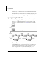
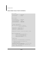
1
Release 1.1 February 2003 Cg Language Toolkit ALL NVIDIA DESIGN SPECIFICATIONS, REFERENCE BOARDS, FILES, DRAWINGS, DIAGNOSTICS, LISTS, AND OTHER DOCUMENTS (TOGETHER AND SEPARATELY, "MATERIALS") ARE BEING PROVIDED "AS IS." NVIDIA MAKES NO WARRANTIES, EXPRESSED, IMPLIED, STATUTORY, OR OTHERWISE WITH RESPECT TO THE MATERIALS, AND EXPRESSLY DISCLAIMS ALL IMPLIED WARRANTIES OF NONINFRINGEMENT, MERCHANTABILITY, AND FITNESS FOR A PARTICULAR PURPOSE. Information furnished is believed to be accurate and reliable. However, NVIDIA Corporation assumes no responsibility for the consequences of use of such information or for any infringement of patents or other rights of third parties that may result from its use. No license is granted by implication or otherwise under any patent or patent rights of NVIDIA Corporation. Specifications mentioned in this publication are subject to change without notice. This publication supersedes and replaces all information previously supplied. NVIDIA Corporation products are not authorized for use as critical components in life support devices or systems without express written approval of NVIDIA Corporation. Trademarks NVIDIA and the NVIDIA logo are trademarks of NVIDIA Corporation. Microsoft, Windows, the Windows logo, and DirectX are registered trademarks of Microsoft Corporation. OpenGL is a trademark of SGI. Other company and product names may be trademarks of the respective companies with which they are associated. Updates Any changes, additions, or corrections will be posted at the NVIDIA Cg Web site: http://developer.nvidia.com/Cg Refer to this site often to keep up on the latest changes and additions to the Cg language. Copyright Copyright NVIDIA Corporation 2002 NVIDIA Corporation 2701 San Tomas Expressway Santa Clara, CA 95050 www.nvidia.com Table of Contents Foreword. . . . . . . . . . . . . . . . . . . . . . . . . . . . . . . . . . . . . . . . . . . . . . . . . . . . . . . . . . . . xi Preface . . . . . . . . . . . . . . . . . . . . . . . . . . . . . . . . . . . . . . . . . . . . . . . . . . . . . . . . . . . . xiii Release Notes . . . . . . . . . . . . . . . . . . . . . . . . . . . . . . . . . . . . . . . . . . . . . . . . . . . . . xiv Online Updates. . . . . . . . . . . . . . . . . . . . . . . . . . . . . . . . . . . . . . . . . . . . . . . . . . . . . xiv Introduction to the Cg Language . . . . . . . . . . . . . . . . . . . . . . . . . . . . . . . . . . . . . . . . . . . . . . . . . . 1 The Cg Language . . . . . . . . . . . . . . . . . . . . . . . . . . . . . . . . . . . . . . . . . . . . . . . . . . . . 1 Cg’s Programming Model for GPUs . . . . . . . . . . . . . . . . . . . . . . . . . . . . . . . . . . . . . . 2 Cg Language Profiles . . . . . . . . . . . . . . . . . . . . . . . . . . . . . . . . . . . . . . . . . . . . . . . 3 Declaring Programs in Cg . . . . . . . . . . . . . . . . . . . . . . . . . . . . . . . . . . . . . . . . . . . . 4 Program Inputs and Outputs . . . . . . . . . . . . . . . . . . . . . . . . . . . . . . . . . . . . . . . . . . 4 Working with Data . . . . . . . . . . . . . . . . . . . . . . . . . . . . . . . . . . . . . . . . . . . . . . . . . . 10 Basic Data Types . . . . . . . . . . . . . . . . . . . . . . . . . . . . . . . . . . . . . . . . . . . . . . . . . 10 Type Conversions . . . . . . . . . . . . . . . . . . . . . . . . . . . . . . . . . . . . . . . . . . . . . . . . . 11 Structures . . . . . . . . . . . . . . . . . . . . . . . . . . . . . . . . . . . . . . . . . . . . . . . . . . . . . . 12 Arrays . . . . . . . . . . . . . . . . . . . . . . . . . . . . . . . . . . . . . . . . . . . . . . . . . . . . . . . . . 12 Statements and Operators . . . . . . . . . . . . . . . . . . . . . . . . . . . . . . . . . . . . . . . . . . . . . 13 Control Flow . . . . . . . . . . . . . . . . . . . . . . . . . . . . . . . . . . . . . . . . . . . . . . . . . . . . 13 Function Definitions and Function Overloading . . . . . . . . . . . . . . . . . . . . . . . . . . . . 14 Arithmetic Operators from C . . . . . . . . . . . . . . . . . . . . . . . . . . . . . . . . . . . . . . . . . 14 Multiplication Functions. . . . . . . . . . . . . . . . . . . . . . . . . . . . . . . . . . . . . . . . . . . . . 15 Vector Constructor . . . . . . . . . . . . . . . . . . . . . . . . . . . . . . . . . . . . . . . . . . . . . . . . 15 Boolean and Comparison Operators . . . . . . . . . . . . . . . . . . . . . . . . . . . . . . . . . . . . 15 Swizzle Operator . . . . . . . . . . . . . . . . . . . . . . . . . . . . . . . . . . . . . . . . . . . . . . . . . 16 Write Mask Operator. . . . . . . . . . . . . . . . . . . . . . . . . . . . . . . . . . . . . . . . . . . . . . . 16 Conditional Operator. . . . . . . . . . . . . . . . . . . . . . . . . . . . . . . . . . . . . . . . . . . . . . . 17 Texture Lookups in Advanced Fragment Profiles . . . . . . . . . . . . . . . . . . . . . . . . . . . 17 More Details . . . . . . . . . . . . . . . . . . . . . . . . . . . . . . . . . . . . . . . . . . . . . . . . . . . . 18 Cg Standard Library Functions . . . . . . . . . . . . . . . . . . . . . . . . . . . . . . . . . . . . . . . . . Mathematical Functions . . . . . . . . . . . . . . . . . . . . . . . . . . . . . . . . . . . . . . . . . . . . . . . Geometric Functions . . . . . . . . . . . . . . . . . . . . . . . . . . . . . . . . . . . . . . . . . . . . . . . . . Texture Map Functions . . . . . . . . . . . . . . . . . . . . . . . . . . . . . . . . . . . . . . . . . . . . . . . Derivative Functions . . . . . . . . . . . . . . . . . . . . . . . . . . . . . . . . . . . . . . . . . . . . . . . . . Debugging Function . . . . . . . . . . . . . . . . . . . . . . . . . . . . . . . . . . . . . . . . . . . . . . . . . Predefined Fragment Program Output Structures . . . . . . . . . . . . . . . . . . . . . . . . . . . . . 808-00504-0000-004 NVIDIA 19 19 24 25 27 28 28 i Cg Language Toolkit Using the Cg Runtime Library . . . . . . . . . . . . . . . . . . . . . . . . . . . . . . . . . . . . . . . . . . . . . . . . . 29 Introducing the Cg Runtime . . . . . . . . . . . . . . . . . . . . . . . . . . . . . . . . . . . . . . . . . . . . 29 Benefits of the Cg Runtime . . . . . . . . . . . . . . . . . . . . . . . . . . . . . . . . . . . . . . . . . . 29 Overview of the Cg Runtime . . . . . . . . . . . . . . . . . . . . . . . . . . . . . . . . . . . . . . . . . 30 Core Cg Runtime . . . . . . . . . . . . . . . . . . . . . . . . . . . . . . . . . . . . . . . . . . . . . . . . . . . 34 Core Cg Context . . . . . . . . . . . . . . . . . . . . . . . . . . . . . . . . . . . . . . . . . . . . . . . . . . 35 Core Cg Program . . . . . . . . . . . . . . . . . . . . . . . . . . . . . . . . . . . . . . . . . . . . . . . . . 35 Core Cg Parameter . . . . . . . . . . . . . . . . . . . . . . . . . . . . . . . . . . . . . . . . . . . . . . . . 39 Core Cg Error . . . . . . . . . . . . . . . . . . . . . . . . . . . . . . . . . . . . . . . . . . . . . . . . . . . . 44 API-Specific Cg Runtimes. . . . . . . . . . . . . . . . . . . . . . . . . . . . . . . . . . . . . . . . . . . . . . 45 Parameter Shadowing . . . . . . . . . . . . . . . . . . . . . . . . . . . . . . . . . . . . . . . . . . . . . . 46 OpenGL Cg Runtime . . . . . . . . . . . . . . . . . . . . . . . . . . . . . . . . . . . . . . . . . . . . . . . 46 Direct3D Cg Runtime . . . . . . . . . . . . . . . . . . . . . . . . . . . . . . . . . . . . . . . . . . . . . . 57 A Brief Tutorial . . . . . . . . . . . . . . . . . . . . . . . . . . . . . . . . . . . . . . . . . . . . . . . . . . . . . . 89 Loading the Workspace . . . . . . . . . . . . . . . . . . . . . . . . . . . . . . . . . . . . . . . . . . . . . . . 89 Understanding simple.cg . . . . . . . . . . . . . . . . . . . . . . . . . . . . . . . . . . . . . . . . . . . . . . 90 Program Listing for simple.cg. . . . . . . . . . . . . . . . . . . . . . . . . . . . . . . . . . . . . . . . . 91 Definitions for Structures with Varying Data . . . . . . . . . . . . . . . . . . . . . . . . . . . . . . 92 Passing Arguments . . . . . . . . . . . . . . . . . . . . . . . . . . . . . . . . . . . . . . . . . . . . . . . . 93 Basic Transformations . . . . . . . . . . . . . . . . . . . . . . . . . . . . . . . . . . . . . . . . . . . . . . 93 Prepare for Lighting . . . . . . . . . . . . . . . . . . . . . . . . . . . . . . . . . . . . . . . . . . . . . . . 94 Calculating the Vertex Color. . . . . . . . . . . . . . . . . . . . . . . . . . . . . . . . . . . . . . . . . . 94 Further Experimentation . . . . . . . . . . . . . . . . . . . . . . . . . . . . . . . . . . . . . . . . . . . . 95 Advanced Profile Sample Shaders . . . . . . . . . . . . . . . . . . . . . . . . . . . . . . . . . . . . . . . 97 Improved Skinning . . . . . . . . . . . . . . . . . . . . . . . . . . . . . . . . . . . . . . . . . . . . . . . . . . 98 Description . . . . . . . . . . . . . . . . . . . . . . . . . . . . . . . . . . . . . . . . . . . . . . . . . . . . . 98 Vertex Shader Source Code for Improved Skinning . . . . . . . . . . . . . . . . . . . . . . . . . 99 Improved Water . . . . . . . . . . . . . . . . . . . . . . . . . . . . . . . . . . . . . . . . . . . . . . . . . . . 101 Description . . . . . . . . . . . . . . . . . . . . . . . . . . . . . . . . . . . . . . . . . . . . . . . . . . . . 101 Vertex Shader Source Code for Improved Water . . . . . . . . . . . . . . . . . . . . . . . . . . 102 Pixel Shader Source Code for Improved Water. . . . . . . . . . . . . . . . . . . . . . . . . . . . 104 Melting Paint . . . . . . . . . . . . . . . . . . . . . . . . . . . . . . . . . . . . . . . . . . . . . . . . . . . . . 105 Description . . . . . . . . . . . . . . . . . . . . . . . . . . . . . . . . . . . . . . . . . . . . . . . . . . . . 105 Vertex Shader Source Code for Melting Paint. . . . . . . . . . . . . . . . . . . . . . . . . . . . . 105 Pixel Shader Source Code for Melting Paint . . . . . . . . . . . . . . . . . . . . . . . . . . . . . . 107 MultiPaint. . . . . . . . . . . . . . . . . . . . . . . . . . . . . . . . . . . . . . . . . . . . . . . . . . . . . . . . 109 Description . . . . . . . . . . . . . . . . . . . . . . . . . . . . . . . . . . . . . . . . . . . . . . . . . . . . 109 Vertex Shader Source Code for MultiPaint . . . . . . . . . . . . . . . . . . . . . . . . . . . . . . . 110 Pixel Shader Source Code for MultiPaint . . . . . . . . . . . . . . . . . . . . . . . . . . . . . . . . 111 Ray-Traced Refraction . . . . . . . . . . . . . . . . . . . . . . . . . . . . . . . . . . . . . . . . . . . . . . . 114 Description . . . . . . . . . . . . . . . . . . . . . . . . . . . . . . . . . . . . . . . . . . . . . . . . . . . . 114 Vertex Shader Source Code for Ray-Traced Refraction . . . . . . . . . . . . . . . . . . . . . . 115 Pixel Shader Source Code for Ray-Traced Refraction. . . . . . . . . . . . . . . . . . . . . . . . 116 Skin. . . . . . . . . . . . . . . . . . . . . . . . . . . . . . . . . . . . . . . . . . . . . . . . . . . . . . . . . . . . 119 ii NVIDIA 808-00504-0000-004 Description . . . . . . . . . . . . . . . . . . . . . . . . . . . . . . . . . . . . . . . . . . . . . . . . . . . . .119 Pixel Shader Source Code for Skin . . . . . . . . . . . . . . . . . . . . . . . . . . . . . . . . . . . . .119 Thin Film Effect . . . . . . . . . . . . . . . . . . . . . . . . . . . . . . . . . . . . . . . . . . . . . . . . . . . .124 Description . . . . . . . . . . . . . . . . . . . . . . . . . . . . . . . . . . . . . . . . . . . . . . . . . . . . .124 Vertex Shader Source Code for Thin Film Effect. . . . . . . . . . . . . . . . . . . . . . . . . . . .124 Pixel Shader Source Code for Thin Film Effect . . . . . . . . . . . . . . . . . . . . . . . . . . . . .126 Car Paint 9. . . . . . . . . . . . . . . . . . . . . . . . . . . . . . . . . . . . . . . . . . . . . . . . . . . . . . . .127 Description . . . . . . . . . . . . . . . . . . . . . . . . . . . . . . . . . . . . . . . . . . . . . . . . . . . . .127 Vertex Shader Source Code for Car Paint 9 . . . . . . . . . . . . . . . . . . . . . . . . . . . . . . .128 Pixel Shader Source Code for Car Paint 9 . . . . . . . . . . . . . . . . . . . . . . . . . . . . . . . .130 Basic Profile Sample Shaders . . . . . . . . . . . . . . . . . . . . . . . . . . . . . . . . . . . . . . . . . 133 Anisotropic Lighting . . . . . . . . . . . . . . . . . . . . . . . . . . . . . . . . . . . . . . . . . . . . . . . . .134 Description . . . . . . . . . . . . . . . . . . . . . . . . . . . . . . . . . . . . . . . . . . . . . . . . . . . . .134 Vertex Shader Source Code for Anisotropic Lighting. . . . . . . . . . . . . . . . . . . . . . . . .135 Bump Dot3x2 Diffuse and Specular . . . . . . . . . . . . . . . . . . . . . . . . . . . . . . . . . . . . . .136 Description . . . . . . . . . . . . . . . . . . . . . . . . . . . . . . . . . . . . . . . . . . . . . . . . . . . . .136 Vertex Shader Source Code for Bump Dot3x2 . . . . . . . . . . . . . . . . . . . . . . . . . . . . .137 Pixel Shader Source Code for Bump Dot3x2 . . . . . . . . . . . . . . . . . . . . . . . . . . . . . .138 Bump-Reflection Mapping . . . . . . . . . . . . . . . . . . . . . . . . . . . . . . . . . . . . . . . . . . . . .140 Description . . . . . . . . . . . . . . . . . . . . . . . . . . . . . . . . . . . . . . . . . . . . . . . . . . . . .140 Vertex Shader Source Code for Bump-Reflection Mapping . . . . . . . . . . . . . . . . . . . .141 Pixel Shader Source Code for Bump and Reflection Mapping. . . . . . . . . . . . . . . . . . .143 Fresnel . . . . . . . . . . . . . . . . . . . . . . . . . . . . . . . . . . . . . . . . . . . . . . . . . . . . . . . . . .144 Description . . . . . . . . . . . . . . . . . . . . . . . . . . . . . . . . . . . . . . . . . . . . . . . . . . . . .144 Vertex Shader Source Code for Fresnel. . . . . . . . . . . . . . . . . . . . . . . . . . . . . . . . . .144 Grass . . . . . . . . . . . . . . . . . . . . . . . . . . . . . . . . . . . . . . . . . . . . . . . . . . . . . . . . . . .146 Description . . . . . . . . . . . . . . . . . . . . . . . . . . . . . . . . . . . . . . . . . . . . . . . . . . . . .146 Vertex Shader Source Code for Grass . . . . . . . . . . . . . . . . . . . . . . . . . . . . . . . . . . .146 Refraction . . . . . . . . . . . . . . . . . . . . . . . . . . . . . . . . . . . . . . . . . . . . . . . . . . . . . . . .149 Description . . . . . . . . . . . . . . . . . . . . . . . . . . . . . . . . . . . . . . . . . . . . . . . . . . . . .149 Vertex Shader Source Code for Refraction. . . . . . . . . . . . . . . . . . . . . . . . . . . . . . . .150 Pixel Shader Source Code for Refraction . . . . . . . . . . . . . . . . . . . . . . . . . . . . . . . . .151 Shadow Mapping . . . . . . . . . . . . . . . . . . . . . . . . . . . . . . . . . . . . . . . . . . . . . . . . . . .152 Description . . . . . . . . . . . . . . . . . . . . . . . . . . . . . . . . . . . . . . . . . . . . . . . . . . . . .152 Vertex Shader Source Code for Shadow Mapping. . . . . . . . . . . . . . . . . . . . . . . . . . .153 Pixel Shader Source Code for Shadow Mapping . . . . . . . . . . . . . . . . . . . . . . . . . . . .154 Shadow Volume Extrusion . . . . . . . . . . . . . . . . . . . . . . . . . . . . . . . . . . . . . . . . . . . . .155 Description . . . . . . . . . . . . . . . . . . . . . . . . . . . . . . . . . . . . . . . . . . . . . . . . . . . . .155 Vertex Shader Source Code for Shadow Volume Extrusion . . . . . . . . . . . . . . . . . . . .156 Sine Wave Demo . . . . . . . . . . . . . . . . . . . . . . . . . . . . . . . . . . . . . . . . . . . . . . . . . . .158 Description . . . . . . . . . . . . . . . . . . . . . . . . . . . . . . . . . . . . . . . . . . . . . . . . . . . . .158 Vertex Shader Source Code for Sine Wave . . . . . . . . . . . . . . . . . . . . . . . . . . . . . . .159 Matrix Palette Skinning . . . . . . . . . . . . . . . . . . . . . . . . . . . . . . . . . . . . . . . . . . . . . . .161 Description . . . . . . . . . . . . . . . . . . . . . . . . . . . . . . . . . . . . . . . . . . . . . . . . . . . . .161 Vertex Shader Source Code for Matrix Palette Skinning . . . . . . . . . . . . . . . . . . . . . .162 808-00504-0000-004 NVIDIA iii Cg Language Toolkit Appendix A Cg Language Specification . . . . . . . . . . . . . . . . . . . . . . . . . . . . . . . . . . . . . . . . . . 165 Language Overview . . . . . . . . . . . . . . . . . . . . . . . . . . . . . . . . . . . . . . . . . . . . . . . . 165 Silent Incompatibilities . . . . . . . . . . . . . . . . . . . . . . . . . . . . . . . . . . . . . . . . . . . . 165 Similar Operations That Must be Expressed Differently . . . . . . . . . . . . . . . . . . . . . . 165 Differences from ANSI C . . . . . . . . . . . . . . . . . . . . . . . . . . . . . . . . . . . . . . . . . . . 166 Detailed Language Specification . . . . . . . . . . . . . . . . . . . . . . . . . . . . . . . . . . . . . . . . 168 Definitions . . . . . . . . . . . . . . . . . . . . . . . . . . . . . . . . . . . . . . . . . . . . . . . . . . . . . 168 Profiles . . . . . . . . . . . . . . . . . . . . . . . . . . . . . . . . . . . . . . . . . . . . . . . . . . . . . . . 168 The Uniform Modifier . . . . . . . . . . . . . . . . . . . . . . . . . . . . . . . . . . . . . . . . . . . . . 169 Function Declarations . . . . . . . . . . . . . . . . . . . . . . . . . . . . . . . . . . . . . . . . . . . . . 169 Overloading of Functions by Profile . . . . . . . . . . . . . . . . . . . . . . . . . . . . . . . . . . . 170 Syntax for Parameters in Function Definitions . . . . . . . . . . . . . . . . . . . . . . . . . . . . 171 Function Calls . . . . . . . . . . . . . . . . . . . . . . . . . . . . . . . . . . . . . . . . . . . . . . . . . . 171 Types . . . . . . . . . . . . . . . . . . . . . . . . . . . . . . . . . . . . . . . . . . . . . . . . . . . . . . . . 171 Partial Support of Types . . . . . . . . . . . . . . . . . . . . . . . . . . . . . . . . . . . . . . . . . . . 173 Type Categories . . . . . . . . . . . . . . . . . . . . . . . . . . . . . . . . . . . . . . . . . . . . . . . . . 174 Constants . . . . . . . . . . . . . . . . . . . . . . . . . . . . . . . . . . . . . . . . . . . . . . . . . . . . . 174 Type Qualifiers . . . . . . . . . . . . . . . . . . . . . . . . . . . . . . . . . . . . . . . . . . . . . . . . . . 175 Type Conversions . . . . . . . . . . . . . . . . . . . . . . . . . . . . . . . . . . . . . . . . . . . . . . . . 176 Type Equivalency . . . . . . . . . . . . . . . . . . . . . . . . . . . . . . . . . . . . . . . . . . . . . . . . 178 Type-Promotion Rules . . . . . . . . . . . . . . . . . . . . . . . . . . . . . . . . . . . . . . . . . . . . . 178 Namespaces . . . . . . . . . . . . . . . . . . . . . . . . . . . . . . . . . . . . . . . . . . . . . . . . . . . 179 Arrays and Subscripting . . . . . . . . . . . . . . . . . . . . . . . . . . . . . . . . . . . . . . . . . . . 179 Function Overloading . . . . . . . . . . . . . . . . . . . . . . . . . . . . . . . . . . . . . . . . . . . . . 181 Global Variables . . . . . . . . . . . . . . . . . . . . . . . . . . . . . . . . . . . . . . . . . . . . . . . . . 182 Use of Uninitialized Variables . . . . . . . . . . . . . . . . . . . . . . . . . . . . . . . . . . . . . . . . 182 Preprocessor . . . . . . . . . . . . . . . . . . . . . . . . . . . . . . . . . . . . . . . . . . . . . . . . . . . 182 Overview of Binding Semantics . . . . . . . . . . . . . . . . . . . . . . . . . . . . . . . . . . . . . . . . 183 Binding Semantics . . . . . . . . . . . . . . . . . . . . . . . . . . . . . . . . . . . . . . . . . . . . . . . 183 Aliasing of Semantics . . . . . . . . . . . . . . . . . . . . . . . . . . . . . . . . . . . . . . . . . . . . . 184 Restrictions on Semantics Within a Structure. . . . . . . . . . . . . . . . . . . . . . . . . . . . . 184 Additional Details for Binding Semantics . . . . . . . . . . . . . . . . . . . . . . . . . . . . . . . . 184 How Programs Receive and Return Data . . . . . . . . . . . . . . . . . . . . . . . . . . . . . . . . 185 Statements . . . . . . . . . . . . . . . . . . . . . . . . . . . . . . . . . . . . . . . . . . . . . . . . . . . . 185 Minimum Requirements for if, while, and for Statements . . . . . . . . . . . . . . . . . 185 New Vector Operators . . . . . . . . . . . . . . . . . . . . . . . . . . . . . . . . . . . . . . . . . . . . . 186 Arithmetic Precision and Range . . . . . . . . . . . . . . . . . . . . . . . . . . . . . . . . . . . . . . 188 Operator Precedence . . . . . . . . . . . . . . . . . . . . . . . . . . . . . . . . . . . . . . . . . . . . . 188 Operator Enhancements . . . . . . . . . . . . . . . . . . . . . . . . . . . . . . . . . . . . . . . . . . . 188 Operators . . . . . . . . . . . . . . . . . . . . . . . . . . . . . . . . . . . . . . . . . . . . . . . . . . . . . 189 Reserved Words . . . . . . . . . . . . . . . . . . . . . . . . . . . . . . . . . . . . . . . . . . . . . . . . . 191 Cg Standard Library Functions . . . . . . . . . . . . . . . . . . . . . . . . . . . . . . . . . . . . . . . . . 191 Vertex Program Profiles . . . . . . . . . . . . . . . . . . . . . . . . . . . . . . . . . . . . . . . . . . . . . . 192 Mandatory Computation of Position Output . . . . . . . . . . . . . . . . . . . . . . . . . . . . . . 192 iv NVIDIA 808-00504-0000-004 Position Invariance . . . . . . . . . . . . . . . . . . . . . . . Binding Semantics for Outputs. . . . . . . . . . . . . . . Fragment Program Profiles . . . . . . . . . . . . . . . . . . . Binding Semantics for Outputs. . . . . . . . . . . . . . . ... ... ... ... .... .... .... .... ... ... ... ... .... .... .... .... .... .... .... .... ... ... ... ... . . . .192 . . . .193 . . . .193 . . . .193 Appendix B Language Profiles . . . . . . . . . . . . . . . . . . . . . . . . . . . . . . . . . . . . . . . . . . . . . . . . . 195 DirectX Vertex Shader 2.x Profiles (vs_2_*) . . . . . . . . . . . . . . . . . . . . . . . . . . . . . . . .196 Overview. . . . . . . . . . . . . . . . . . . . . . . . . . . . . . . . . . . . . . . . . . . . . . . . . . . . . . .196 Memory. . . . . . . . . . . . . . . . . . . . . . . . . . . . . . . . . . . . . . . . . . . . . . . . . . . . . . . .196 Statements and Operators . . . . . . . . . . . . . . . . . . . . . . . . . . . . . . . . . . . . . . . . . .197 Data Types . . . . . . . . . . . . . . . . . . . . . . . . . . . . . . . . . . . . . . . . . . . . . . . . . . . . .197 Using Arrays . . . . . . . . . . . . . . . . . . . . . . . . . . . . . . . . . . . . . . . . . . . . . . . . . . . .197 Bindings . . . . . . . . . . . . . . . . . . . . . . . . . . . . . . . . . . . . . . . . . . . . . . . . . . . . . . .198 Options . . . . . . . . . . . . . . . . . . . . . . . . . . . . . . . . . . . . . . . . . . . . . . . . . . . . . . . .199 DirectX Pixel Shader 2.x Profiles (ps_2_*) . . . . . . . . . . . . . . . . . . . . . . . . . . . . . . . . .200 Memory. . . . . . . . . . . . . . . . . . . . . . . . . . . . . . . . . . . . . . . . . . . . . . . . . . . . . . . .200 Language Constructs and Support . . . . . . . . . . . . . . . . . . . . . . . . . . . . . . . . . . . . .201 Bindings . . . . . . . . . . . . . . . . . . . . . . . . . . . . . . . . . . . . . . . . . . . . . . . . . . . . . . .202 Options . . . . . . . . . . . . . . . . . . . . . . . . . . . . . . . . . . . . . . . . . . . . . . . . . . . . . . . .203 Limitations in this Implementation . . . . . . . . . . . . . . . . . . . . . . . . . . . . . . . . . . . . .203 OpenGL ARB Vertex Program Profile (arbvp1) . . . . . . . . . . . . . . . . . . . . . . . . . . . . . .204 Overview. . . . . . . . . . . . . . . . . . . . . . . . . . . . . . . . . . . . . . . . . . . . . . . . . . . . . . .204 Accessing OpenGL State . . . . . . . . . . . . . . . . . . . . . . . . . . . . . . . . . . . . . . . . . . . .204 Position Invariance . . . . . . . . . . . . . . . . . . . . . . . . . . . . . . . . . . . . . . . . . . . . . . . .206 Data Types . . . . . . . . . . . . . . . . . . . . . . . . . . . . . . . . . . . . . . . . . . . . . . . . . . . . .207 Compatibility with the vp20 Vertex Program Profile . . . . . . . . . . . . . . . . . . . . . . . . .207 Loading Constants . . . . . . . . . . . . . . . . . . . . . . . . . . . . . . . . . . . . . . . . . . . . . . . .208 Bindings . . . . . . . . . . . . . . . . . . . . . . . . . . . . . . . . . . . . . . . . . . . . . . . . . . . . . . .208 OpenGL ARB Fragment Program Profile (arbfp1) . . . . . . . . . . . . . . . . . . . . . . . . . . . .211 Memory. . . . . . . . . . . . . . . . . . . . . . . . . . . . . . . . . . . . . . . . . . . . . . . . . . . . . . . .211 Language Constructs and Support . . . . . . . . . . . . . . . . . . . . . . . . . . . . . . . . . . . . .212 Bindings . . . . . . . . . . . . . . . . . . . . . . . . . . . . . . . . . . . . . . . . . . . . . . . . . . . . . . .212 Options . . . . . . . . . . . . . . . . . . . . . . . . . . . . . . . . . . . . . . . . . . . . . . . . . . . . . . . .213 Limitations in the Implementation . . . . . . . . . . . . . . . . . . . . . . . . . . . . . . . . . . . . .213 OpenGL NV_vertex_program 2.0 Profile (vp30). . . . . . . . . . . . . . . . . . . . . . . . . . . . . .214 Position Invariance . . . . . . . . . . . . . . . . . . . . . . . . . . . . . . . . . . . . . . . . . . . . . . . .214 Language Constructs . . . . . . . . . . . . . . . . . . . . . . . . . . . . . . . . . . . . . . . . . . . . . .214 Bindings . . . . . . . . . . . . . . . . . . . . . . . . . . . . . . . . . . . . . . . . . . . . . . . . . . . . . . .215 OpenGL NV_fragment_program Profile (fp30) . . . . . . . . . . . . . . . . . . . . . . . . . . . . . .218 Language Constructs and Support . . . . . . . . . . . . . . . . . . . . . . . . . . . . . . . . . . . . .218 Bindings . . . . . . . . . . . . . . . . . . . . . . . . . . . . . . . . . . . . . . . . . . . . . . . . . . . . . . .219 Pack and Unpack Functions . . . . . . . . . . . . . . . . . . . . . . . . . . . . . . . . . . . . . . . . . .220 DirectX Vertex Shader 1.1 Profile (vs_1_1) . . . . . . . . . . . . . . . . . . . . . . . . . . . . . . . .223 Memory Restrictions . . . . . . . . . . . . . . . . . . . . . . . . . . . . . . . . . . . . . . . . . . . . . . .223 Language Constructs and Support . . . . . . . . . . . . . . . . . . . . . . . . . . . . . . . . . . . . .223 808-00504-0000-004 NVIDIA v Cg Language Toolkit Bindings . . . . . . . . . . . . . . . . . . . . . . . . . . . . . . . . . . . . . . . . . . . . . . . . . . . . . . Options . . . . . . . . . . . . . . . . . . . . . . . . . . . . . . . . . . . . . . . . . . . . . . . . . . . . . . . DirectX Pixel Shader 1.x Profiles (ps_1_*) . . . . . . . . . . . . . . . . . . . . . . . . . . . . . . . . Overview . . . . . . . . . . . . . . . . . . . . . . . . . . . . . . . . . . . . . . . . . . . . . . . . . . . . . . Modifiers . . . . . . . . . . . . . . . . . . . . . . . . . . . . . . . . . . . . . . . . . . . . . . . . . . . . . . Language Constructs and Support . . . . . . . . . . . . . . . . . . . . . . . . . . . . . . . . . . . . Standard Library Functions . . . . . . . . . . . . . . . . . . . . . . . . . . . . . . . . . . . . . . . . . Bindings . . . . . . . . . . . . . . . . . . . . . . . . . . . . . . . . . . . . . . . . . . . . . . . . . . . . . . Auxiliary Texture Functions . . . . . . . . . . . . . . . . . . . . . . . . . . . . . . . . . . . . . . . . . Examples. . . . . . . . . . . . . . . . . . . . . . . . . . . . . . . . . . . . . . . . . . . . . . . . . . . . . . OpenGL NV_vertex_program 1.0 Profile (vp20) . . . . . . . . . . . . . . . . . . . . . . . . . . . . . Overview . . . . . . . . . . . . . . . . . . . . . . . . . . . . . . . . . . . . . . . . . . . . . . . . . . . . . . Position Invariance . . . . . . . . . . . . . . . . . . . . . . . . . . . . . . . . . . . . . . . . . . . . . . . Data Types . . . . . . . . . . . . . . . . . . . . . . . . . . . . . . . . . . . . . . . . . . . . . . . . . . . . Bindings . . . . . . . . . . . . . . . . . . . . . . . . . . . . . . . . . . . . . . . . . . . . . . . . . . . . . . OpenGL NV_texture_shader and NV_register_combiners Profile (fp20) . . . . . . . . . . . . Overview . . . . . . . . . . . . . . . . . . . . . . . . . . . . . . . . . . . . . . . . . . . . . . . . . . . . . . Restrictions . . . . . . . . . . . . . . . . . . . . . . . . . . . . . . . . . . . . . . . . . . . . . . . . . . . . Modifiers . . . . . . . . . . . . . . . . . . . . . . . . . . . . . . . . . . . . . . . . . . . . . . . . . . . . . . Language Constructs and Support . . . . . . . . . . . . . . . . . . . . . . . . . . . . . . . . . . . . Standard Library Functions . . . . . . . . . . . . . . . . . . . . . . . . . . . . . . . . . . . . . . . . . Bindings . . . . . . . . . . . . . . . . . . . . . . . . . . . . . . . . . . . . . . . . . . . . . . . . . . . . . . Auxiliary Texture Functions . . . . . . . . . . . . . . . . . . . . . . . . . . . . . . . . . . . . . . . . . Examples. . . . . . . . . . . . . . . . . . . . . . . . . . . . . . . . . . . . . . . . . . . . . . . . . . . . . . 225 226 227 227 228 229 230 232 234 239 240 240 240 241 241 244 244 244 245 246 247 249 251 256 Appendix C Nine Steps to High-Performance Cg . . . . . . . . . . . . . . . . . . . . . . . . . . . . . . . . . . . 257 Appendix D Cg Compiler Options . . . . . . . . . . . . . . . . . . . . . . . . . . . . . . . . . . . . . . . . . . . . . . . 265 vi NVIDIA 808-00504-0000-004 Contents, Figures, and Tables List of Figures Figure 1 Cg’s Model of the GPU . . . . . . . . . . . . . . . . . . . . . . . . . . . . . 2 Figure 2 The Parts of the Cg Runtime API . . . . . . . . . . . . . . . . . . . . . . . .31 Figure 3 The Cg_Simple Workspace . . . . . . . . . . . . . . . . . . . . . . . . . .89 Figure 4 The simple.cg Shader . . . . . . . . . . . . . . . . . . . . . . . . . . . . .90 Figure 5 Example of Improved Skinning . . . . . . . . . . . . . . . . . . . . . . . . .98 Figure 6 Example of Improved Water . . . . . . . . . . . . . . . . . . . . . . . . . 101 Figure 7 Example of Melting Paint . . . . . . . . . . . . . . . . . . . . . . . . . . 105 Figure 8 Example of MultiPaint . . . . . . . . . . . . . . . . . . . . . . . . . . . . 109 Figure 9 Example of Ray-Traced Refraction . . . . . . . . . . . . . . . . . . . . . . 114 Figure 10 Example of Skin . . . . . . . . . . . . . . . . . . . . . . . . . . . . . . 119 Figure 11 Example of Thin Film Effect . . . . . . . . . . . . . . . . . . . . . . . . 124 Figure 12 Example of Car Paint 9 . . . . . . . . . . . . . . . . . . . . . . . . . . . 127 Figure 13 Example of Anisotropic Lighting . . . . . . . . . . . . . . . . . . . . . . . 134 Figure 14 Example of Bump Dot3x2 Diffuse and Specular . . . . . . . . . . . . . . . 136 Figure 15 Example of Bump-Reflection Mapping . . . . . . . . . . . . . . . . . . . . 140 Figure 16 Example of Fresnel Figure 17 Example of Grass . . . . . . . . . . . . . . . . . . . . . . . . . . . . 144 . . . . . . . . . . . . . . . . . . . . . . . . . . . . . 146 Figure 18 Example of Refraction . . . . . . . . . . . . . . . . . . . . . . . . . . . 149 Figure 19 Example of Shadow Mapping . . . . . . . . . . . . . . . . . . . . . . . . 152 Figure 20 Example of Shadow Volume Extrusion . . . . . . . . . . . . . . . . . . . . 155 Figure 21 Example of Sine Wave . . . . . . . . . . . . . . . . . . . . . . . . . . . 158 Figure 22 Example of Matrix Palette Skinning . . . . . . . . . . . . . . . . . . . . . 161 808-00504-0000-004 NVIDIA vii Cg Language Toolkit List of Figures viii NVIDIA 808-00504-0000-004 List of Tables Table 1 Mathematical Functions . . . . . . . . . . . . . . . . . . . . . . . . . . . . .20 Table 2 Geometric Functions . . . . . . . . . . . . . . . . . . . . . . . . . . . . . .24 Table 3 Texture Map Functions . . . . . . . . . . . . . . . . . . . . . . . . . . . . .25 Table 4 Derivative Functions . . . . . . . . . . . . . . . . . . . . . . . . . . . . . .27 Table 5 Debugging Function . . . . . . . . . . . . . . . . . . . . . . . . . . . . . .28 Table 6 Type Conversions . . . . . . . . . . . . . . . . . . . . . . . . . . . . . . . 177 Table 7 Expanded Operators . . . . . . . . . . . . . . . . . . . . . . . . . . . . . 188 Table 8 Vertex Output Binding Semantics . . . . . . . . . . . . . . . . . . . . . . . 193 Table 9 Fragment Output Binding Semantics . . . . . . . . . . . . . . . . . . . . . . 193 Table 10 vs_2_* Uniform Input Binding Semantics . . . . . . . . . . . . . . . . . . 198 Table 11 vs_2_* Varying Input Binding Semantics . . . . . . . . . . . . . . . . . . 198 Table 12 vs_2_* Varying Output Binding Semantics . . . . . . . . . . . . . . . . . . 199 Table 13 ps_2_* Uniform Input Binding Semantics . . . . . . . . . . . . . . . . . . 202 Table 14 ps_2_* Varying Input Binding Semantics . . . . . . . . . . . . . . . . . . 202 Table 15 ps_2_* Varying Output Binding Semantics . . . . . . . . . . . . . . . . . . 202 Table 19 arbvp1 Uniform Input Binding Semantics . . . . . . . . . . . . . . . . . . 208 Table 20 arbvp1 Varying Input Binding Semantics . . . . . . . . . . . . . . . . . . . 209 Table 21 arbvp1 Varying Output Binding Semantics . . . . . . . . . . . . . . . . . . 210 Table 22 arbfp1 Uniform Input Binding Semantics . . . . . . . . . . . . . . . . . . 212 Table 23 arbfp1 Varying Input Binding Semantics . . . . . . . . . . . . . . . . . . 213 Table 24 arbfp1 Varying Output Binding Semantics . . . . . . . . . . . . . . . . . . 213 Table 25 vp30 Uniform Input Binding Semantics . . . . . . . . . . . . . . . . . . . 215 Table 26 vp30 Varying Input Binding Semantics . . . . . . . . . . . . . . . . . . . . 216 Table 27 vp30 Varying Output Binding Semantics . . . . . . . . . . . . . . . . . . . 216 Table 28 fp30 Uniform Input Binding Semantics . . . . . . . . . . . . . . . . . . . 219 Table 29 fp30 Varying Input Binding Semantics . . . . . . . . . . . . . . . . . . . . 219 Table 30 fp30 Varying Output Binding Semantics . . . . . . . . . . . . . . . . . . . 220 Table 31 vs_1_1 Uniform Input Binding Semantics . . . . . . . . . . . . . . . . . . 225 Table 32 vs_1_1 Varying Input Binding Semantics . . . . . . . . . . . . . . . . . . . 225 Table 33 vs_1_1 Varying Output Binding Semantics . . . . . . . . . . . . . . . . . . 226 Table 34 ps_1_x Instruction Set Modifiers . . . . . . . . . . . . . . . . . . . . . . 228 808-00504-0000-004 NVIDIA ix Cg Language Toolkit List of Tables Table 35 Supported Standard Library Functions . . . . . . . . . . . . . . . . . . . . 230 Table 36 Required Projective Texture Lookup Swizzles . . . . . . . . . . . . . . . . . 231 Table 37 ps_1_x Uniform Input Binding Semantics . . . . . . . . . . . . . . . . . . 232 Table 38 ps_1_x Varying Input Binding Semantics . . . . . . . . . . . . . . . . . . 233 Table 39 ps_1_x Varying Output Binding Semantics . . . . . . . . . . . . . . . . . . 233 Table 40 ps_1_x Auxiliary Texture Functions . . . . . . . . . . . . . . . . . . . . . 234 Table 41 vp20 Uniform Input Binding Semantics . . . . . . . . . . . . . . . . . . . 241 Table 42 vp20 Varying Input Binding Semantics . . . . . . . . . . . . . . . . . . . . 242 Table 43 vp20 Varying Output Binding Semantics . . . . . . . . . . . . . . . . . . . 242 Table 44 NV_texture_shader and NV_register_combiners Instruction Set Modifiers . . . . 245 Table 45 Supported Standard Library Functions . . . . . . . . . . . . . . . . . . . . 247 Table 46 Required Projective Texture Lookup Swizzles . . . . . . . . . . . . . . . . . 248 Table 47 fp20 Uniform Binding Semantics . . . . . . . . . . . . . . . . . . . . . . 249 Table 48 fp20 Varying Input Binding Semantics . . . . . . . . . . . . . . . . . . . . 250 Table 49 fp20 Varying Output Binding Semantics . . . . . . . . . . . . . . . . . . . 250 Table 50 fp20 Auxiliary Texture Functions . . . . . . . . . . . . . . . . . . . . . . 251 x NVIDIA 808-00504-0000-004 Foreword We are in the midst of a great transition in computer graphics, both in terms of graphics hardware and in terms of the visual quality and authoring process for games, interactive applications, and animation. Graphics hardware has evolved from “big iron” graphics workstations costing hundreds of thousands of dollars to single-chip graphics processing units (GPUs) whose performance and features have grown to match and now even to exceed traditional workstations. The processing power provided by a modern GPU in a single frame rivals the amount of computation that used to be expended for an offline-rendered animation frame. Indeed, at the launch of GeForce3 on the Apple Macintosh, a convincing version of Pixar’s Luxo, Jr. was demonstrated running interactively in real-time. At the 2001 SIGGRAPH conference, an interactive version of a more recent film, Square Studios’ Final Fantasy, was shown running in realtime, again on a GeForce3. Although these feats of computation are astounding, there is much more to come. Today’s GPUs evolve very quickly. Typically, a product generation is only six months long, and with each new product generation comes a two-fold increase in performance. Graphics processor performance increases at approximately three times the rate of microprocessors-Moore’s Law cubed! In addition to the performance increases, each year brings new hardware features, supported by new application programming interfaces (APIs). This dizzying pace is difficult for developers to adapt to, but adapt they must. Developers and users are demanding better rendering quality and more realistic imagery and experiences. Users don’t care about the details; they simply want games and other interactive applications to look more like movies, special effects, and animation. Developers want more power (always more), along with more flexibility in controlling the massively capable GPUs of today and tomorrow. APIs do not, and cannot, keep up with the rapid pace of innovation in GPUs. As APIs and underlying technologies change, programmers, artists, and software publishers struggle to adapt to the change and the churn of the hardware/software platform. What’s needed is to raise the level of abstraction for interaction with GPUs. Continued updates and improvements to the hardware and APIs are too painful if developers are too “close to the metal.” This problem was exacerbated by the advent of programmability in GPUs. Older GPUs had a small number of controllable or configurable rendering paths, but the most recent technology is 808-00504-0000-004 NVIDIA xi Cg Language Toolkit highly programmable, and becoming ever more so. We can now write short vertex and fragment programs to be executed by the GPU. This requires great skill, and is only possible with short programs. When GPU hardware grows to allow programs of hundreds, thousands, or even more instructions, assembly coding will no longer be practical. Rather than programming each rendering state, each bit, byte, and word of data and control through a low-level assembly language, we want to express our ideas in a more straightforward form, using a high-level language. Thus Cg, “C for Graphics,” becomes necessary and inevitable. Just as C was derived to expose the specific capabilities of processors while allowing higherlevel abstraction, Cg allows the same abstraction for GPUs. Cg changes the way programmers can program: focusing on the ideas, the concepts, and the effects they wish to create-not on the details of the hardware implementation. Cg also decouples programs from specific hardware because the language is functional, not hardware implementation-specific. Also, since Cg can be compiled at run time on any platform, operating system, and for any graphics hardware, Cg programs are truly portable. Finally, and perhaps best of all, Cg programs are future-proof and can adapt to run well on future products. The compiler can optimize directly for a new target GPU that perhaps did not even exist when the original Cg program was written. This book is intended as an introduction to Cg, as well as a practical handbook to get programmers started developing in Cg. It includes a language description, a reference for the standard and run-time libraries, and is full of helpful examples. The goal for this book is to be both an introduction and a tool for the new user, as well as a reference and resource for developers as they become more proficient. Welcome to the world of Cg! David Kirk Chief Scientist NVIDIA Corporation xii NVIDIA 808-00504-0000-004 Preface The goal of this book is to introduce to you Cg, a new high-level language for graphics programming. To that end, we have organized this document into the following sections: “Introduction to the Cg Language” on page 1 A quick introduction to the current release of Cg, with everything you need to know to start working it. “Cg Standard Library Functions” on page 19 A list of the Standard Library functions, which can help to reduce your program development time. “Using the Cg Runtime Library” on page 29 An introduction to the Cg runtime APIs, which allow you to easily compile Cg programs and pass data to them from within applications. “A Brief Tutorial” on page 89 A description of a simple Cg program and Microsoft Visual Studio workspace (both provided on the accompanying CD) that you can use to start experimenting with Cg. “Advanced Profile Sample Shaders” on page 97 A list of sample NV30 shaders, complete with source code. “Basic Profile Sample Shaders” on page 133 A list of sample NV2X shaders, complete with source code. Appendix A, “Cg Language Specification” on page 165 The formal Cg language specification. Appendix B, “Language Profiles” on page 195 Describes features and restrictions of the currently supported language profiles: DirectX 8 vertex, DirectX 8 pixel, OpenGL ARB vertex, NV2X OpenGL vertex, NV30 OpenGL vertex, and NV30 OpenGL fragment. Appendix C, “Nine Steps to High-Performance Cg” on page 257 Strategies for getting the most out of your Cg code. Appendix D, “Cg Compiler Options” on page 265 A list of the various command-line options that the Cg compiler accepts. 808-00504-0000-004 NVIDIA xiii Cg Language Toolkit Cg Developer’s CD The CD provided with this book contains the entire Cg release, which allows you get started immediately. The readme.txt file on the CD describes the contents of the release in detail. You can begin working with Cg immediately by reading the “Introduction to the Cg Language” on page 1 and then going through “A Brief Tutorial” on page 89. Once you have a basic understanding of the Cg language, use the “Advanced Profile Sample Shaders” on page 97 and “Basic Profile Sample Shaders” on page 133 as a basis to build your own effects. Release Notes Release notes for Cg are now contained in a separate document that is part of the Cg distribution. Please report any bugs, issues, and feedback to NVIDIA by e-mailing [email protected]. We will expeditiously address any reported problems. Online Updates Any changes, additions, or corrections are posted at the NVIDIA Cg Web site: http://developer.nvidia.com/Cg Refer to this site often to keep up on the latest changes and additions to the Cg language. Information on how to report any bugs you may find in the release is also available on this site. xiv NVIDIA 808-00504-0000-004 Introduction to the Cg Language Historically, graphics hardware has been programmed at a very low level. Fixedfunction pipelines were configured by setting states such as the texturecombining modes. More recently, programmers configured programmable pipelines by using programming interfaces at the assembly language level. In theory, these low-level programming interfaces provided great flexibility. In practice, they were painful to use and presented a serious barrier to the effective use of hardware. Using a high-level programming language, rather than the low-level languages of the past, provides several advantages: A high-level language speeds up the tweak-and-run cycle when a shader is developed. The ultimate test for a shader is “Does it look right?” To that end, the ability to quickly prototype and modify a shader is crucial to the rapid development of high-quality effects. The compiler optimizes code automatically and performs low-level tasks, such as register allocation, that are tedious and prone to error. Shading code written in a high-level language is much easier to read and understand. It also allows new shaders to be easily created by modifying previously written shaders. What better way to learn than from a shader written by the best artists and programmers? Shaders written in a high-level language are portable to a wider range of hardware platforms than shaders written in assembly code. This chapter introduces Cg (C for Graphics), a new high-level language tailored for programming GPUs. Cg offers all the advantages just described, allowing programmers to finally combine the inherent power of the GPU with a language that makes GPU programming easy. The Cg Language Cg is based on C, but with enhancements and modifications that make it easy to write programs that compile to highly optimized GPU code. Cg code looks 808-00504-0000-004 NVIDIA 1 Cg Language Toolkit almost exactly like C code, with the same syntax for declarations, function calls, and most data types. Before describing the Cg language in detail, it is important to explain the reason for some of the differences that exist between Cg and C. Fundamentally, it comes down to the difference in the programming models for GPUs and for CPUs. Cg’s Programming Model for GPUs CPUs normally have only one programmable processor. In contrast, GPUs have at least two programmable processors, the vertex processor and the fragment processor, plus other non-programmable hardware units. The processors, the non-programmable parts of the graphics hardware, and the application are all linked through data flows. Figure 1 illustrates Cg’s model of the GPU. Figure 1 Cg’s Model of the GPU The Cg language allows you to write programs for both the vertex processor and the fragment processor. We refer to these programs as vertex programs and fragment programs, respectively. (Fragment programs are also known as pixel programs or pixel shaders, and we use these terms interchangeably in this document.) Cg code can be compiled into GPU assembly code, either on demand at run time or beforehand. 2 NVIDIA 808-00504-0000-004 Introduction to the Cg Language Cg makes it easy to combine a Cg fragment program with a handwritten vertex program, or even with the non-programmable OpenGL or DirectX vertex pipeline. Likewise, a Cg vertex program can be combined with a handwritten fragment program, or with the non-programmable OpenGL or DirectX fragment pipeline. Cg Language Profiles Because all CPUs support essentially the same set of basic capabilities, the C language supports this set on all CPUs. However, GPU programmability has not quite yet reached this same level of generality. For example, the current generation of programmable vertex processors supports a greater range of capabilities than do the programmable fragment processors. Cg addresses this issue by introducing the concept of language profiles. A Cg profile defines a subset of the full Cg language that is supported on a particular hardware platform or API. The current release of the Cg compiler supports the following profiles: DirectX 9 vertex shaders Runtime profiles: CG_PROFILE_VS_2_X Compiler options: CG_PROFILE_VS_2_0 -profile vs_2_x -profile vs_2_0 DirectX 9 pixel shaders Runtime profiles: CG_PROFILE_PS_2_X Compiler options: CG_PROFILE_PS_2_0 -profile ps_2_x -profile ps_2_0 OpenGL ARB vertex programs Runtime profile: CG_PROFILE_ARBVP1 -profile arbvp1 Compiler option: OpenGL ARB fragment programs Runtime profile: CG_PROFILE_ARBFP1 -profile arbfp1 Compiler option: OpenGL NV30 vertex programs CG_PROFILE_VP30 Runtime profile: Compiler option: -profile vp30 OpenGL NV30 fragment programs Runtime profile: CG_PROFILE_FP30 Compiler option: -profile fp30 808-00504-0000-004 NVIDIA 3 Cg Language Toolkit DirectX 8 vertex shaders CG_PROFILE_VS_1_1 Runtime profile: Compiler option: -profile vs_1_1 DirectX 8 pixel shaders Runtime profiles: CG_PROFILE_PS_1_3 Compiler options: CG_PROFILE_PS_1_2 CG_PROFILE_PS_1_1 -profile ps_1_3 -profile ps_1_2 -profile ps_1_1 OpenGL NV2X vertex programs CG_PROFILE_VP20 Runtime profile: -profile vp20 Compiler option: OpenGL NV2X fragment programs CG_PROFILE_FP20 Runtime profile: Compiler option: -profile fp20 The DirectX 9 profiles (vs_2_x and ps_2_x), OpenGL ARB profiles (arbfp1 and arbvp1), and NV30 OpenGL profiles (fp30 and vp30) generally support longer, more complex programs and offer more features and functionality to the developer. These are referred to as advanced profiles. The DirectX 8 profiles (vs_1_1 and ps_1_3) and NV2X OpenGL profiles (fp20 and vp20) have more restrictions on program length and available features, especially in fragment programs. These are referred to as basic profiles. See “Language Profiles” on page 195 for detailed descriptions of these and related profiles. Declaring Programs in Cg CPU code generally consists of one program specified by main() in C. In contrast, a Cg program can have any name. A program is defined using the following syntax: <return-type> <program-name>(<parameters>)[: <semantic-name>] { /* ... */ } Program Inputs and Outputs The programmable processors in GPUs operate on streams of data. The vertex processor operates on a stream of vertices, and the fragment processor operates on a stream of fragments. 4 NVIDIA 808-00504-0000-004 Introduction to the Cg Language A programmer can think of the main program as being executed just once on a CPU. In contrast, a program is executed repeatedly on a GPU—once for each element of data in a stream. The vertex program is executed once for each vertex, and the fragment program is executed once for each fragment. The Cg language adds several capabilities to C to support this stream-based programming model. For new Cg programmers, these capabilities often take some time to understand because they have no direct correspondence to C capabilities. However, the sample programs later in this document demonstrate that it really is easy to use these capabilities in Cg programs. Two Kinds of Program Inputs A Cg program can consume two different kinds of inputs: Varying inputs are used for data that is specified with each element of the stream of input data. For example, the varying inputs to a vertex program are the per-vertex values that are specified in vertex arrays. For a fragment program, the varying inputs are the interpolants, such as texture coordinates. Uniform inputs are used for values that are specified separately from the main stream of input data, and don’t change with each stream element. For example, a vertex program typically requires a transformation matrix as a uniform input. Often, uniform inputs are thought of as graphics state. Varying Inputs to a Vertex Program A vertex program typically consumes several different per-vertex (varying) inputs. For example, the program might require that the application specify the following varying inputs for each vertex, typically in a vertex array: Model space position Model space normal vector Texture coordinate In a fixed-function graphics pipeline, the set of possible per-vertex inputs is small and predefined. This predefined set of inputs is exposed to the application through the graphics API. For example, OpenGL 1.4 provides the ability to specify a vertex array of normal vectors. In a programmable graphics pipeline, there is no longer a small set of predefined inputs. It is perfectly reasonable for the developer to write a vertex program that uses a per-vertex refractive index value as long as the application provides this value with each vertex. Cg provides a flexible mechanism for specifying these per-vertex inputs in the form of a set of predefined names. Each program input must be bound to a 808-00504-0000-004 NVIDIA 5 Cg Language Toolkit name from this set. In the following structure, the vertex program definition binds its parameters to the predefined names POSITION, NORMAL, TANGENT, and TEXCOORD3. The application must provide the vertex array data associated with these predefined names. struct myinputs { float3 myPosition float3 myNormal float3 myTangent float refractive_index }; : : : : POSITION; NORMAL; TANGENT; TEXCOORD3; outdata foo(myinputs indata) { /* ... */ // Within the program, the parameters are referred to as // “indata.myPosition”, “indata.myNormal”, and so on. /* ... */ } We refer to the predefined names as binding semantics. The following set of binding semantics is supported in all Cg vertex program profiles. Some Cg profiles support additional binding semantics. POSITION NORMAL BINORMAL BLENDINDICES BLENDWEIGHT TANGENT PSIZE TEXCOORD0—TEXCOORD7 The binding semantic POSITION0 is equivalent to the binding semantic POSITION; likewise, the other binding semantics have similar equivalents. In the OpenGL Cg profiles, binding semantics implicitly specify the mapping of varying inputs to particular hardware registers. However, in DirectX-based Cg profiles there is no such implied mapping. Binding semantics may be specified directly on program parameters rather than on struct elements. Thus, the following vertex program definition is legal: outdata foo(float3 myPosition : POSITION, float3 myNormal : NORMAL, float3 myTangent : TANGENT, float refractive_index : TEXCOORD3) { /* ... */ // Within the program, the parameters are referred to by // their variable names: “myPosition”, “myNormal”, // “myTangent”, and “refractive_index”. /* ... */ } 6 NVIDIA 808-00504-0000-004 Introduction to the Cg Language Varying Outputs to and from Vertex Programs The outputs of a vertex program pass through the rasterizer and are made available to a fragment program as varying inputs. For a vertex program and fragment program to interoperate, they must agree on the data being passed between them. As it does with the data flow between the application and vertex program, Cg uses binding semantics to specify the data flow between the vertex program and fragment program. This example shows the use of binding semantics for vertex program output: // Vertex program struct myvf { float4 pout float4 diffusecolor float4 uv0 float4 uv1 }; myvf foo(/* ... */) { myvf outstuff; /* ... */ return outstuff; } : : : : POSITION; // Used for rasterization COLOR0; TEXCOORD0; TEXCOORD1; And, this example shows how to use this same data as the input to a fragment program: // Fragment program struct myvf { float4 diffusecolor : COLOR0; float4 uv0 : TEXCOORD0; float4 uv1 : TEXCOORD1; }; fragout bar(myvf indata) { float4 x = indata.uv0; /* ... */ } The following binding semantics are available in all Cg vertex profiles for output from vertex programs: POSITION, PSIZE, FOG, COLOR0–COLOR1, and TEXCOORD0–TEXCOORD7. All vertex programs must declare and set a vector output that uses the binding semantic. This value is required for rasterization. POSITION 808-00504-0000-004 NVIDIA 7 Cg Language Toolkit To ensure interoperability between vertex programs and fragment programs, both must use the same struct for their respective outputs and inputs. For example struct myvert2frag { float4 pos : POSITION; float4 uv0 : TEXCOORD0; float4 uv1 : TEXCOORD1; }; // Vertex program myvert2frag vertmain(...) { myvert2frag outdata; /* ... */ return outdata; } // Fragment program void fragmain(myvert2frag indata ) { float4 tcoord = indata.uv0; /* ... */ } Note that values associated with some vertex output semantics are intended for and are used by the rasterizer. These values cannot actually be used in the fragment program, even though they appear in the input struct. For example, the indata.pos value associated with the POSITION fragment semantic may not be read in the fragmain shader. Varying Outputs from Fragment Programs Binding semantics are always required on the outputs of fragment programs. Fragment programs are required to declare and set a vector output that uses the COLOR semantic. This value is usually used by the hardware as the final color of the fragment. Some fragment profiles also support the DEPTH output semantic, which allows the depth value of the fragment to be modified. As with vertex programs, fragment programs may return their outputs in the body of a structure. However, it is usually more convenient to either declare outputs as out parameters: void main(/* ... */, out float4 color : COLOR, out float depth : DEPTH) { /* ...*/ color = diffuseColor * /* ...*/; depth = /*...*/; } 8 NVIDIA 808-00504-0000-004 Introduction to the Cg Language or to associate a semantic with the return value of the shader: float4 main(/* ... */) : COLOR { /* ... */ return diffuseCOlor * /* ... */; } The following example shows a simple vertex program that calculates diffuse and specular lighting. Two structures for varying data, appin and vertout, are also declared. Don’t worry about understanding exactly what the program is doing—the goal is simply to give you an idea of what Cg code looks like. “A Brief Tutorial” on page 89 explains this shader in detail. // Define inputs from application. struct appin { float4 Position : POSITION; float4 Normal : NORMAL; }; // Define outputs from vertex shader. struct vertout { float4 HPosition : POSITION; float4 Color : COLOR; }; vertout main(appin IN, uniform float4x4 ModelViewProj, uniform float4x4 ModelViewIT, uniform float4 LightVec) { vertout OUT; // Transform vertex position into homogenous clip-space. OUT.HPosition = mul(ModelViewProj, IN.Position); // Transform normal from model-space to view-space. float3 normalVec = normalize(mul(ModelViewIT, IN.Normal).xyz); // Store normalized light vector. float3 lightVec = normalize(LightVec.xyz); // Calculate half angle vector. float3 eyeVec = float3(0.0, 0.0, 1.0); float3 halfVec = normalize(lightVec + eyeVec); 808-00504-0000-004 NVIDIA 9 Cg Language Toolkit // Calculate diffuse component. float diffuse = dot(normalVec, lightVec); // Calculate specular component. float specular = dot(normalVec, halfVec); // Use the lit function to compute lighting vector from // diffuse and specular values. float4 lighting = lit(diffuse, specular, 32); // Blue diffuse material float3 diffuseMaterial = float3(0.0, 0.0, 1.0); // White specular material float3 specularMaterial = float3(1.0, 1.0, 1.0); // Combine diffuse and specular contributions and // output final vertex color. OUT.Color.rgb = lighting.y * diffuseMaterial + lighting.z * specularMaterial; OUT.Color.a = 1.0; return OUT; } Working with Data Like C, Cg supports features that create and manipulate data: Basic types Structures Arrays Type conversions Basic Data Types Cg supports six basic data types: float A 32-bit IEEE floating point (s23e8) number that has one sign bit, a 23-bit mantissa, and an 8-bit exponent. This type is supported in all profiles, 10 NVIDIA 808-00504-0000-004 Introduction to the Cg Language although the DirectX 8 pixel profiles implement it with reduced precision and range for some operations. half A 16-bit IEEE-like floating point (s10e5) number. int A 32-bit integer. Profiles may omit support for this type or have the option to treat int as float. fixed A 12-bit fixed-point number (s1.10) number. It is supported in all fragment profiles. bool Boolean data is produced by comparisons and is used in if and conditional operator (?:) constructs. This type is supported in all profiles. sampler* The handle to a texture object comes in six variants: sampler, sampler1D, sampler2D, sampler3D, samplerCUBE, and samplerRECT. These types are supported in all pixel and fragment profiles, with one exception: samplerRECT is not supported in the DirectX profiles. Cg also includes built-in vector data types that are based on the basic data types. A sample of these built-in vector data types includes (but is not limited to) the following: float4 bool4 float3 bool3 float2 bool2 float1 bool1 Additional support is provided for matrices of up to four-by-four elements. Here are some examples of matrix declarations: float1x1 float2x3 float4x2 float4x4 matrix1; matrix2; matrix3; matrix4; // // // // One element matrix Two-by-three matrix (six elements) Four-by-two matrix (eight elements) Four-by-four matrix (sixteen elements) Note that the multi-dimensional array float M[4][4] is not type-equivalent to the matrix float4x4 M. There are no unions or bit fields in Cg at present. Type Conversions Type conversions in Cg work largely as they do in C. Type conversions may be explicitly specified using the C (newtype) cast operator. 808-00504-0000-004 NVIDIA 11 Cg Language Toolkit Cg automatically performs type promotion in mixed-type expressions, just as C does. For example, the expression floatvar * halfvar is compiled as floatvar * (float) halfvar. Cg uses different type-promotion rules than C does in one case: A constant without an explicit type suffix does not cause type promotion. CG compiles the expression halfvar * 2.0 as halfvar * (half) 2.0. In contrast, C would compile it as ((double) halfvar) * 2.0. Cg uses different rules than C to minimize inadvertent type promotions that cause computations to be performed in slower, high-precision arithmetic. If the C behavior is desired, the constant should be explicitly typed to force the type promotion: halfvar * 2.0f is compiled as ((float) halfvar) * 2.0f. Cg uses the following type suffixes for constants: f for float h for half x for fixed Structures Cg supports structures the same way C does. Cg adopts the C++ convention of implicitly performing a typedef based on the tag name when a struct is declared: struct mystruct { /* ... */ }; mystruct s; // Define “s” as a “mystruct”. Arrays Arrays are supported in Cg and are declared just as in C. Because Cg does not support pointers, arrays must always be defined using array syntax rather than pointer syntax: // Declare a function that accepts an array // of five skinning matrices. returnType foo(float4x4 mymatrix[5]) {/* ... */}; Basic profiles place substantial restrictions on array declaration and usage. General-purpose arrays can only be used as uniform parameters to a vertex program. The intent is to allow an application to pass arrays of skinning matrices and arrays of light parameters to a vertex program. The most important difference from C is that arrays are first-class types. That means array assignments actually copy the entire array, and arrays that are 12 NVIDIA 808-00504-0000-004 Introduction to the Cg Language passed as parameters are passed by value (the entire array is copied before making any changes), rather than by reference. Statements and Operators Cg supports the following types of statements and operators: Control flow Function definitions and function overloads Arithmetic operators from C Multiplication function Vector constructor Boolean and comparison operators Swizzle operator Write mask operator Conditional operator Control Flow Cg uses the following C control constructs: Function calls and the return statement if/else while for These control constructs require that their conditional expressions be of type bool. Because Cg expressions like i <= 3 are of type bool, this change from C is normally not apparent. The vs_2_x and vp30 profiles support branch instructions, so for and while loops are fully supported in these profiles. In other profiles, for and while loops may only be used if the compiler can fully unroll them (that is, if the compiler can determine the iteration count at compile time). Likewise, return can only appear as the last statement in a function in these profiles. Function recursion (and co-recursion) is forbidden in Cg. The switch, case, and default keywords are reserved, but they are not supported by any profiles in the current release of the Cg compiler. 808-00504-0000-004 NVIDIA 13 Cg Language Toolkit Function Definitions and Function Overloading To pass a modifiable function parameter in C, the programmer must explicitly use pointers. C++ provides a built-in pass-by-reference mechanism that avoids the need to explicitly use pointers, but this mechanism still implicitly assumes that the hardware supports pointers. Cg must use a different mechanism because the vertex and fragment hardware of the GPU does not support the use of pointers. Cg passes modifiable function parameters by value-result, instead of by reference. The difference between these two methods is subtle; it is only apparent when two function parameters are aliased by a function call. In Cg, the two parameters have separate storage in the function, whereas in C++ they would share storage. To reinforce this distinction, Cg uses a different syntax than C++ to declare function parameters that are modified: function function function function blah1(out blah2(inout blah3(in blah4(float float x); // x is output-only float x); // x is input and output float x); // x is input-only x); // x is input-only (default, as in C) Cg supports function overloading by the number of operands and by operand type. The choice of a function is made by matching one operand at a time, starting at the first operand. The formal language specification provides more details on the matching rules, but it is not normally necessary to study them because the overloading generally works in an intuitive manner. For example, the following code declares two versions of a function, one that takes two bool operands, and one that takes two float operands: bool same(float a, float b) bool same(bool a, bool b) { return (a == b);} { return (a == b);} Arithmetic Operators from C Cg includes all the standard C arithmetic operators (+, -, *, /) and allows the operators to be used on vectors as well as on scalars. The vector operations are always performed in elementwise fashion. For example, float3(a, b, c) * float3(A, B, C) equals float3(a*A, b*B, c*C) These operators can also be used in a form that mixes scalar and vector—the scalar is “smeared” to create a vector of the necessary size to perform an elementwise operation. Thus, a * float3(A, B, C) is equal to float3(a*A, a*B, a*C) The built-in arithmetic operators do not currently support matrix operands. It is important to remember that matrices are not the same as vectors, even if their dimensions are the same. 14 NVIDIA 808-00504-0000-004 Introduction to the Cg Language Multiplication Functions Cg’s mul() functions are for multiplying matrices by vectors, and matrices by matrices: // Matrix by column-vector multiply matrix-column vector: mul(M, v); // Row-vector by matrix multiply row vector-matrix: mul(v, M); // Matrix by matrix multiply matrix-matrix: mul(M, N); It is important to use the correct version of mul(). Otherwise, you are likely to get unexpected results. More detail on the mul() functions are provided in “Cg Standard Library Functions” on page 19. Vector Constructor Cg allows vectors (up to size 4) to be constructed using the following notation: y = x * float4(3.0, 2.0, 1.0, -1.0); The vector constructor can appear anywhere in an expression. Boolean and Comparison Operators Cg includes three of the standard C boolean operators: && logical AND || logical OR ! logical negation In C, these operators consume and produce values of type int, but in Cg they consume and produce values of type bool. This difference is not normally noticeable, except when declaring a variable that will hold the value of a boolean expression. Cg also supports the C comparison operators, which produce values of type bool: < less than <= less than or equal to != inequality == equality >= greater than or equal to > greater than 808-00504-0000-004 NVIDIA 15 Cg Language Toolkit Unlike C, Cg allows all boolean operators to be applied to vectors, in which case boolean operations are performed in an elementwise fashion. The result of such a boolean expression is a vector of bool elements with that number of elements being the same as the two source vectors. Also unlike C, the logical AND (&&) and logical OR (||) operators cannot be used for short-circuiting evaluation; side effects of both sides of these expressions always occur, regardless of the value of the boolean expression. Swizzle Operator Cg has a swizzle operator (.) that allows the components of a vector to be rearranged to form a new vector. The new vector need not be the same size as the original vector—elements can be repeated or omitted. The characters x, y, z, and w represent the first, second, third, and fourth components of the original vector, respectively. The characters r, g, b, and a can be used for the same purpose. Because the swizzle operator is implemented efficiently in the GPU hardware, its use is usually free. The following are some examples of swizzling: float3(a, b, c).zyx yields float3(c, b, a) float4(a, b, c, d).xxyy yields float4(a, a, b, b) float2(a, b).yyxx yields float4(b, b, a, a) yields d float4(a, b, c, d).w The swizzle operator can also be used to create a vector from a scalar: a.xxxx yields float4(a, a, a, a) The precedence of the swizzle operator is the same as that of the array subscripting operator ([]). Write Mask Operator The write mask operator (.) is placed on the left hand side of an assignment statement. It can be used to selectively overwrite the components of a vector. It is illegal to specify a particular component more than once in a write mask, or to specify a write mask when initializing a variable as part of a declaration. The following is an example of a write mask: float4 color = float4(1.0, 1.0, 0.0, 0.0); color.a = 1.0; // Set alpha to 1.0, leaving RGB alone. The write mask operator can be a powerful tool for generating efficient code because it maps well to the capabilities of GPU hardware. The precedence of the write mask operator is the same as that of the swizzle operator. 16 NVIDIA 808-00504-0000-004 Introduction to the Cg Language Conditional Operator Cg includes C’s if/else conditional statement and conditional operator (?:). With the conditional operator, the control variable may be a bool vector. If so, the second and third operands must be similarly sized vectors, and selection is performed on an elementwise basis. Unlike C, any side effects associated with the second and third operands always occur, regardless of the conditional. As an example, the following would be a very efficient way to implement a vector clamp function, if the min() and max() functions did not exist: float3 clamp(float3 x, float minval, float maxval) { x = (x < minval.xxx) ? minval.xxx : x; x = (x > maxval.xxx) ? maxval.xxx : x; return x; } Texture Lookups in Advanced Fragment Profiles Cg’s advanced fragment profiles provide a variety of texture lookup functions. Please note that Cg uses a different set of texture lookup functions for basic fragment profiles because of the restricted pixel programmability of that hardware. Basic fragment profile lookup functions aren’t discussed in this introductory chapter. Advanced fragment profile texture lookup functions always require at least two parameters: Texture sampler A texture sampler is a variable with the type sampler, sampler1D, sampler2D, sampler3D, samplerCUBE, or samplerRECT and represents the combination of a texture image with a filter, clamp, wrap, or similar configuration. Texture sampler variables cannot be set directly within the Cg language; instead, they must be provided by the application as uniform parameters to a Cg program. Texture coordinate Depending on the type of texture lookup, the coordinate may be a scalar, a two-vector, a three-vector, or a four-vector. The following fragment program uses the tex2D() function to perform a 2D texture lookup to determine the fragment’s RGBA color. void applytex(uniform sampler2D mytexture, float2 uv : TEXCOORD0, out float4 outcolor : COLOR) { outcolor = tex2D(mytexture, uv); } 808-00504-0000-004 NVIDIA 17 Cg Language Toolkit Cg provides a wide variety of texture-lookup functions, a sample of which is given below. For a complete list see “Texture Map Functions” on page 25. Standard nonprojective texture lookup: tex2D (sampler2D tex, float2 s); texRECT (samplerRECT tex, float2 s); texCUBE (samplerCUBE tex, float3 s); Standard projective texture lookup: tex2Dproj (sampler2D tex, float3 sq); texRECTproj (samplerRECT tex, float3 sq) texCUBEproj (samplerCUBE tex, float4 sq); Nonprojective texture lookup with user-specified filter kernel size: tex2D (sampler2D tex, float2 s, float2 dsdx, float2 dsdy); texRECT (samplerRECT tex, float2 s, float2 dsdx, float2 dsdy); texCUBE (samplerCUBE tex, float3 s, float3 dsdx, float3 dsdy); The filter size is specified by providing the derivatives of the texture coordinates with respect to pixel coordinates x (dsdx) and y (dsdy). For more information see “Texture Map Functions” on page 25. Shadowmap lookup: tex2Dproj (sampler2D tex, float4 szq); tex2DRECT (samplerRECT tex, float4 szq); In these functions, the z component of the texture coordinate holds a depth value to be compared against the shadowmap. Shadowmap lookups require the associated texture unit to be configured by the application for depth compare texturing; otherwise, no depth comparison is actually performed. More Details The purpose of this chapter has been to give you a brief overview of Cg, so that you can get started quickly and experiment to gain hands-on experience. If you would like some more detail about any of the language features described in this chapter, see “Cg Language Specification” on page 165. 18 NVIDIA 808-00504-0000-004 Cg Standard Library Functions Cg provides a set of built-in functions and predefined structures with binding semantics to simplify GPU programming. These functions are similar in spirit to the C standard library, providing a convenient set of common functions. In many cases, the functions map to a single native GPU instruction, meaning they are executed very quickly. Of those functions that map to multiple native GPU instructions, you may expect the most useful to become more efficient in the near future. Although customized versions of specific functions can be written for performance or precision reasons, it is generally wiser to use the standard library functions when possible. The standard library functions will continue to be optimized for future GPUs, meaning that a shader written today will automatically be optimized for the latest architectures at compile time. Additionally, the standard library provides a convenient unified interface for both vertex and fragment programs. This section describes the contents of the Cg Standard Library, including Mathematical functions Geometric functions Texture map functions Derivative functions Predefined helper struct types Where appropriate, functions are overloaded to support scalar and vector variations when the input and output types are the same. Mathematical Functions Table 1 lists the mathematical functions that the Cg Standard Library provides. The list includes functions useful for trigonometry, exponentiation, rounding, 808-00504-0000-004 NVIDIA 19 Cg Language Toolkit and vector and matrix manipulations, among others. All functions work on scalars and vectors of all sizes, except where noted. Table 1 Mathematical Functions Mathematical Functions 20 Function Description abs(x) Absolute value of x acos(x) Arccosine of x in range [0,π], x in [-1,1] all(x) Returns true if every component of x is not equal to 0. Returns false otherwise. any(x) Returns true if any component of x is not equal to 0. Returns false otherwise. asin(x) Arcsine of x in range [-π/2,π/2]; x should be in [-1,1]. atan(x) Arctangent of x in range [-π/2,π/2] atan2(y, x) Arctangent of y/x in range [-π,π] ceil(x) Smallest integer not less than x clamp(x, a, b) x clamped to the range [a,b] as follows: • Returns a if x is less than a. • Returns b if x is greater than b. • Returns x otherwise. cos(x) Cosine of x cosh(x) Hyperbolic cosine of x cross(a, b) Cross product of vectors a and b; a and b must be 3-component vectors. degress(x) Radian-to-degree conversion determinant(M) Determinant of matrix M dot(a, b) Dot product of vectors a and b exp(x) Exponential function ex exp2(x) Exponential function 2x floor(x) Largest integer not greater than x NVIDIA 808-00504-0000-004 Cg Standard Library Functions Table 1 Mathematical Functions (continued) Mathematical Functions Function Description fmod(x, y) Remainder of x/y, with the same sign as x. If y is zero, the result is implementation-defined. frac(x) Fractional part of x frexp(x, out exp) Splits x into a normalized fraction in the interval [1/2, 1), which is returned, and a power of 2, which is stored in exp. If x is zero, both parts of the result are zero. isfinite(x) Returns true if x is finite isinf(x) Returns true if x is infinite isnan(x) Returns true if x is NaN (not a number) n ldexp(x, n) x * 2 lerp(a, b, f) Linear interpolation: (1-f)*a + b*f where a and b are matching vector or scalar types. Parameter f can be either a scalar or a vector of the same type as a and b. lit(ndotl, ndoth, m) Computes lighting coefficients for ambient, diffuse, and specular light contributions. Returns a 4-vector as follows: • The x component of the result vector contains the ambient coefficient, which is always 1.0. • The y component contains the diffuse coefficient which is zero if (n z l) < 0; otherwise (n z l). • The z component contains the specular coefficient which is zero if either (n z l) < 0 or (n z h) < 0; (n z h)m otherwise. • The w component is 1.0. There is no vectorized version of this function log(x) Natural logarithm ln(x); x must be greater than zero. log2(x) Base 2 logarithm of x; x must be greater than zero. log10(x) Base 10 logarithm of x; x must be greater than zero. max(a, b) Maximum of a and b 808-00504-0000-004 NVIDIA 21 Cg Language Toolkit Table 1 Mathematical Functions (continued) Mathematical Functions Function Description min(a, b) Minimum of a and b modf(x, out ip) Splits x into integral and fractional parts, each with the same sign as x. Stores the integral part in ip and returns the fractional part. mul(M, N) Matrix product of matrix M and matrix N, as shown below: mul(M, N) = M11 M12 M13 M14 M21 M22 M23 M24 M31 M32 M33 M34 M41 M42 M43 M44 N11 N12 N13 N14 N21 N22 N23 N23 N31 N32 N33 N34 N41 N42 N43 N44 If M has size AxB, and N has size BxC, returns a matrix of size AxC. mul(M, v) Product of matrix M and column vector v, as shown below: mul(M, v) = M11 M12 M13 M14 M21 M22 M23 M24 M31 M32 M33 M34 M41 M42 M43 M44 V1 V2 V3 V4 If M is an AxB matrix and v is an Bx1 vector, returns an Ax1 vector. mul(v, M) Product of row vector v and matrix M, as shown below: mul(v, M) = [V1 V2 V3 M11 M V4] 12 M13 M14 M21 M22 M23 M24 M31 M32 M33 M34 M41 M42 M43 M44 If v is a 1xA vector and M is an AxB matrix, returns a 1xB vector. 22 noise(x) Either a 1-, 2-, or 3-dimensional noise function depending on the type of its argument. The returned value is between zero and one and is always the same for a given input value. pow(x, y) xy radians(x) Degree-to-radian conversion NVIDIA 808-00504-0000-004 Cg Standard Library Functions Table 1 Mathematical Functions (continued) Mathematical Functions Function Description round(x) Closest integer to x rsqrt(x) Reciprocal square root of x; x must be greater than zero. sign(x) 1 if x > 0; -1 if x < 0; 0 otherwise. sin(x) Sine of x sincos(float x, out s, out c) s is set to the sine of x, and c is set to the cosine of x. If sin(x) and cos(x) are both needed, this function is more efficient than calculating each individually. sinh(x) Hyperbolic sine of x smoothstep(min, max, x) For values of x between min and max, returns a smoothly varying value that ranges from 0 at x = min to 1 at x = max. x is clamped to the range [min,max] and then the interpolation formula is evaluated: -2*((x-min)/(max-min))3 + 3*((x-min)/(max-min))2 step(a, x) 0 if x < a; 1 if x >= a. sqrt(x) Square root of x; x must be greater than zero. tan(x) Tangent of x tanh(x) Hyperbolic tangent of x transpose(M) Matrix transpose of matrix M. If M is an AxB matrix, the transpose of M is a BxA matrix whose first column is the first row of M, whose second column is the second row of M, whose third column is the third row of M, and so on. 808-00504-0000-004 NVIDIA 23 Cg Language Toolkit Geometric Functions Table 2 presents the geometric functions that are provided in the Cg Standard Library. Table 2 Geometric Functions Geometric Functions 24 Function Description distance(pt1, pt2) Euclidean distance between points pt1 and pt2 faceforward(N, I, Ng) N if dot(Ng,I) < 0; otherwise, -N. length(v) Euclidean length of a vector normalize(v) Returns a vector of length 1 that points in the same direction as vector v. reflect(i, n) Computes reflection vector from entering ray direction i and surface normal n. Only valid for 3-component vectors. refract(i, n, eta) Given entering ray direction i, surface normal n, and relative index of refraction eta, computes refraction vector. If the angle between i and n is too large for a given eta, returns (0,0,0). Only valid for 3-component vectors. NVIDIA 808-00504-0000-004 Cg Standard Library Functions Texture Map Functions Table 3 presents the texture functions that are provided in the Cg Standard Library. These texture functions are fully supported by the ps_2, arbfp1, and fp30 profiles and will also be supported by all future profiles that have texturemapping capabilities. All of the functions in Table 3 return a float4 value. Because of the limited pixel programmability of older hardware, the ps_1 and profiles use a different set of texture-mapping functions. See “Language Profiles” on page 195 for more information. fp20 Table 3 Texture Map Functions Texture Map Functions Function Description tex1D(sampler1D tex, float s) 1D nonprojective tex1D(sampler1D tex, float s, float dsdx, float dsdy) 1D nonprojective with derivatives tex1D(sampler1D tex, float2 sz) 1D nonprojective depth compare tex1D(sampler1D tex, float2 sz, float dsdx, float dsdy) 1D nonprojective depth compare with derivatives tex1Dproj(sampler1D tex, float2 sq) 1D projective tex1Dproj(sampler1D tex, float3 szq) 1D projective depth compare tex2D(sampler2D tex, float2 s) 2D nonprojective tex2D(sampler2D tex, float2 s, float2 dsdx, float2 dsdy) 2D nonprojective with derivatives tex2D(sampler2D tex, float3 sz) 2D nonprojective depth compare 808-00504-0000-004 NVIDIA 25 Cg Language Toolkit Table 3 Texture Map Functions (continued) Texture Map Functions Function Description tex2D(sampler2D tex, float3 sz, float2 dsdx, float2 dsdy) 2D nonprojective depth compare with derivatives tex2Dproj(sampler2D tex, float3 sq) 2D projective tex2Dproj(sampler2D tex, float4 szq) 2D projective depth compare texRECT(samplerRECT tex, float2 s) 2D RECT nonprojective texRECT(samplerRECT tex, float2 s, float2 dsdx, float2 dsdy) 2D RECT nonprojective with derivatives texRECT(samplerRECT tex, float3 sz) 2D RECT nonprojective depth compare texRECT(samplerRECT tex, float3 sz, float2 dsdx, float2 dsdy) 2D RECT nonprojective depth compare with derivatives texRECTproj(samplerRECT tex, float3 sq) 2D RECT projective texRECTproj(samplerRECT tex, float3 szq) 2D RECT projective depth compare tex3D(sampler3D tex, float3 s) 3D nonprojective tex3D(sampler3D tex, float3 s, float3 dsdx, float3 dsdy) 3D nonprojective with derivatives tex3Dproj(sampler3D tex, float4 szq) 3D projective depth compare 26 NVIDIA 808-00504-0000-004 Cg Standard Library Functions Table 3 Texture Map Functions (continued) Texture Map Functions Function Description texCUBE(samplerCUBE tex, float3 s) Cubemap nonprojective texCUBE(samplerCUBE tex, float3 s, float3 dsdx, float3 dsdy) Cubemap nonprojective with derivatives texCUBEproj(samplerCUBE tex, float4 sq) Cubemap projective In the table, the name of the second argument to each function indicates how its values are used when performing the texture lookup: s indicates a 1-, 2-, or 3-component texture coordinate; z indicates a depth comparison value for shadowmap lookups; q indicates a perspective value and is used to divide the texture coordinate, s, before the texture lookup is performed. For convenience, the standard library also defines versions of the texture functions prefixed with h4, such as h4tex2D(), that return half4 values and prefixed with x4, such as x4tex2D(), that return fixed4 values. When the texture functions that allow specifying a depth comparison value are used, the associated texture unit must be configured for depth compare texturing. Otherwise, no depth comparison is actually performed. Derivative Functions Table 4 presents the derivative functions that are supported by the Cg Standard Library. Vertex profiles are not required to support these functions. Table 4 Derivative Functions Derivative Functions Function Description ddx(a) Approximate partial derivative of a with respect to screen-space x coordinate. ddy(a) Approximate partial derivative of a with respect to screen-space y coordinate. 808-00504-0000-004 NVIDIA 27 Cg Language Toolkit Debugging Function Table 5 presents the debugging function that is supported by the Cg Standard Library. Vertex profiles are not required to support this function. Table 5 Debugging Function Debugging Function Function Description void debug(float4 x) If the compiler’s DEBUG option is specified, calling this function causes the value x to be copied to the COLOR output of the program, and execution of the program is terminated. If the compiler’s DEBUG option is not specified, this function does nothing. The debug function is intended to allow a program to be compiled twice—once with the DEBUG option and once without. By executing both programs, you can obtain one frame buffer containing the final output of the program and a second containing an intermediate value to be examined for debugging. Predefined Fragment Program Output Structures A number of helper structure types for use in fragment programs are predefined in the standard library. Variables of these types can be used to hold the outputs of a fragment program. Their use is strictly optional. For the ps_1 and fp20 profiles, the fragout structure is defined as follows: struct fragout { float4 col : COLOR; }; The ps_2, arbfp1, and fp30 profiles have two fragment output types defined: struct fragout { half4 col : COLOR; float depth : DEPTH; }; struct fragout_float { float4 col : COLOR; float depth : DEPTH; }; 28 NVIDIA 808-00504-0000-004 Using the Cg Runtime Library This chapter describes the Cg Runtime Library. It assumes that you have some basic knowledge of the Cg language, as well as the OpenGL or Direct3D APIs, depending on which one you use in your applications. The first section “Introducing the Cg Runtime” on page 29 talks about the benefits of using the Cg Runtime Library and gives a brief overview of how it is used in an application. The next two sections, “Core Cg Runtime” on page 34 and “API-Specific Cg Runtimes” on page 45, give an exhaustive description of the APIs composing the Cg Runtime. Introducing the Cg Runtime Cg programs are lines of code that describe shading, but they need the support of applications to create images. To interface Cg programs with applications, you must do two things: 1. Compile the programs for the correct profile. In other words, compile the programs into a form that is compatible with the 3D API used by the application and the underlying hardware. 2. Link the programs to the application program. This allows the application to feed varying and uniform data to the programs. You have two choices as to when to perform these operations. You can perform them at compile time, when the application program is compiled into an executable, or you can perform them at run time, when the application is actually executed. The Cg runtime is an application programming interface that allows an application to compile and link Cg programs at run time. Benefits of the Cg Runtime Future Compatibility Most applications need to run on a range of profiles. If an application precompiles its Cg programs (the compile-time choice), it must store a compiled version of each program for each profile. This is reasonable for one 808-00504-0000-004 NVIDIA 29 Cg Language Toolkit program, but is cumbersome for an application that uses many programs. What’s worse, the application is frozen in time. It supports only the profiles that existed when it was compiled; it cannot take advantage of the optimizations that future compilers could offer. In contrast, programs compiled by applications at run time Benefit from future compiler optimizations for the existing profiles Run on future profiles corresponding to new 3D APIs or to hardware that did not exist at the time the Cg programs were written No Dependency Limitations If you link a Cg program to the application when it is compiled, the application is too dependent on the result of the compilation. The application program has to refer to the Cg program input parameters by using the hardware register names that are output by the Cg compiler. This approach is awkward for two reasons: The register names can’t be easily matched to the corresponding meaningful names in the Cg program without looking at the compiler output. Register allocations can change each time the Cg program, the Cg compiler, or the compilation profile changes. This means you have the inconvenience of updating the application each time as well. In contrast, linking a Cg program to the application program at run time removes the dependency on the Cg compiler. With the runtime, you need to alter the application code only when you add, delete, or modify Cg input parameters. Input Parameter Management The Cg runtime also offers additional facilities to manage the input parameters of the Cg program. In particular, it makes data types such as arrays and matrices easier to deal with. These additional functions also encompass the necessary 3D API calls to minimize code length and reduce programmer errors. Overview of the Cg Runtime The Cg runtime API consists of three parts (Figure 2): 30 A core set of functions and structures that encapsulates the entire functionality of the runtime A set of functions specific to OpenGL built on top of the core set A set of functions specific to Direct3D built on top of the core set NVIDIA 808-00504-0000-004 Using the Cg Runtime Library To make it easier for application writers, the OpenGL and Direct3D runtime libraries adopt the philosophy and data structure style of their respective API. Figure 2 The Parts of the Cg Runtime API The rest of the section provides instructions for using the Cg runtime in the framework of an application. Each step includes source code for OpenGL and Direct3D programming. Functions that involve only pure Cg resource management belong to the core runtime and have a cg prefix. In these cases, the same code is used for OpenGL and Direct3D. When functions from the OpenGL or Direct3D Cg runtimes are used, notice that the API name is indicated by the function name. Functions belonging to the OpenGL Cg runtime library have a cgGL prefix, and functions in the Direct3D Cg runtime library have a cgD3D prefix. There are actually two Direct3D Cg runtime libraries: One for Direct3D 8 and one for Direct3D 9. Functions belonging to the Direct3D 8 Cg runtime have a cgD3D8 prefix, and functions belonging to the Direct3D 9 Cg runtime have a cgD3D9 prefix. Because most of the functions are identical between the two runtimes, we describe the Direct3D 9 Cg runtime with the understanding that the description applies to the Direct3D 8 Cg runtime as well, unless otherwise indicated. The same prefix convention used for the function names is also used for the type names, macro names and enumerant values. 808-00504-0000-004 NVIDIA 31 Cg Language Toolkit Header Files Here is how to include the core Cg runtime API into your C or C++ program: #include <Cg/cg.h> Here is how to include the OpenGL Cg runtime API: #include <Cg/cgGL.h> Here is how to include the Direct3D 9 Cg runtime API: #include <Cg/cgD3D9.h> And, here is how to include the Direct3D 8 Cg runtime API: #include <Cg/cgD3D8.h> Creating a Context A context is a container for multiple Cg programs. It holds the Cg programs, as well as their shared data. Here’s how to create a context: CGcontext context = cgCreateContext(); Compiling a Program Compile a Cg program by adding it to a context with cgCreateProgram(): CGprogram program = cgCreateProgram(context, CG_SOURCE, myVertexProgramString, CG_PROFILE_ARBVP1, "main", args); indicates that myVertexProgramString, a string argument, contains Cg source code, not precompiled object code. Indeed, the Cg runtime also lets you create a program from precompiled object code, if you want to. CG_SOURCE CG_PROFILE_ARBVP1 is the profile the program is to be compiled to. The “main” parameter gives the name of the function to use as the main entry point when the program is executed. Lastly, args is a null-terminated list of null- terminated strings that is passed as an argument to the compiler. Loading a Program After you compile a program, you need to pass the resulting object code to the 3D API that you’re using. For this, you need to invoke the Cg runtime’s APIspecific functions. The Direct3D-specific functions require the Direct3D device structure in order to make the necessary Direct3D calls. The application passes it to the runtime using the following call: cgD3D9SetDevice(Device); 32 NVIDIA 808-00504-0000-004 Using the Cg Runtime Library You must do this every time a new Direct3D device is created, typically only at the beginning of the application. You can then load a Cg program in this way for the Direct3D 9 Cg runtime: cgD3D9LoadProgram(program, CG_FALSE, 0); or this way for the Direct3D 8 Cg runtime: cgD3D8LoadProgram(program, CG_FALSE, 0, 0, vertexDeclaration); The parameter vertexDeclaration is the Direct3D 8 vertex declaration array that describes where to find the necessary vertex attributes in the vertex streams. (See “Expanded Interface Program Execution” on page 74 for the details on the arguments to cgD3D8LoadProgram()and cgD3D9LoadProgram()). In OpenGL, the equivalent call is cgGLLoadProgram(program); Modifying Program Parameters The runtime gives you the option of modifying the values of your program parameters. The first step is to get a handle to the parameter: CGparameter myParameter = cgGetNamedParameter( program, "myParameter"); The variable “myParameter” is the name of the parameter as it appears in the program source code. The second step is to set the parameter value. The function used depends on the parameter type. Here is an example in OpenGL: cgGLSetParameter4fv(myParameter, value); Here is the same example in Direct3D: cgD3D9SetUniform(myParameter, value); These function calls assign the four floating-point values contained in the array to the parameter myParameter, which is assumed to be of type float4. value In both APIs, there are variants of these calls to set matrices, arrays, textures, and texture states. Executing a Program Before you can execute a program in OpenGL, you must enable its corresponding profile: cgGLEnableProfile(CG_PROFILE_ARBVP1); 808-00504-0000-004 NVIDIA 33 Cg Language Toolkit In Direct3D, nothing explicitly needs to be done to enable a specific profile. Next, you bind the program to the current state. This means that in subsequent drawing calls the program is executed for every vertex in the case of a vertex program and for every fragment in the case of a fragment program. Here’s how to bind a program in OpenGL: cgGLBindProgram(program); Here’s how to bind a program in Direct3D: cgD3D9BindProgram(program); You can only bind one vertex and one fragment program at a time for a particular profile. Therefore, the same vertex program is executed until another vertex program is bound. Similarly, the same fragment program is executed as long as no other fragment program is bound. In OpenGL, you disable profiles by the following call: cgGLDisableProfile(CG_PROFILE_ARBVP1); Disabling a profile also disables the execution of the corresponding vertex or fragment program. Releasing Resources When your application is ready to close, it is good programming practice to free resources that you’ve acquired. Because the Direct3D runtime keeps an internal reference to the Direct3D device, you must tell it to release this reference when you are done using the runtime. This is done with the following call: cgD3D9SetDevice(0); To free resources allocated for a program, call this function: cgDestroyProgram(program); To free resources allocated for a context, use this function: cgDestroyContext(context); Note that destroying a context destroys all the programs it contains as well. Core Cg Runtime The core Cg runtime provides all the functions necessary to manage Cg programs from within the application. It makes no assumption about which 3D API the applications uses, so that any application could easily ignore the APIspecific Cg runtime libraries and content itself with the core Cg runtime. 34 NVIDIA 808-00504-0000-004 Using the Cg Runtime Library The core Cg runtime is built around three main concepts: context, program, and parameter, which are represented by the CGcontext, CGprogram, and CGparameter object types. Those concepts are hierarchically related one to each other: a program has several parameters, a context contains several programs, and the application can define several contexts. Note: In the future, it will also be possible to define parameters at the level of the context so that they are shared among all the programs of a context. The next sections go over those three basic object types and the related functions. The three object types have some points in common: The use of CGbool, which is an integer type equal to either CG_TRUE or CG_FALSE The use of CGenum, which is an enumerate type used to specify various enumerate values that are not necessarily related The convention that functions that return a value of type CGcontext, CGprogram, CGparameter, or const char* indicate failure by returning zero Core Cg Context Cg provides functions for creating, destroying, and querying contexts. Context Creation and Destruction Programs can only be created as part of a context that acts as a program container. A context is created by calling cgCreateContext(): CGcontext cgCreateContext(); A context is destroyed by cgDestroyContext(): void cgDestroyContext(CGcontext context); Context Query To check whether a context handle references a valid context or not, use cgIsContext(): CGbool cgIsContext(CGcontext context); Core Cg Program There are Cg functions for creating, destroying, iterating over, and querying programs. 808-00504-0000-004 NVIDIA 35 Cg Language Toolkit Program Creation and Destruction A program is created by calling either cgCreateProgram(): CGprogram cgCreateProgram(CGcontext CGenum const char* CGprofile const char* const char** context, programType, program, profile, entry, args); or cgCreateProgramFromFile(): CGprogram cgCreateProgramFromFile(CGcontext CGenum const char* CGprofile const char* const char** context, programType, program, profile, entry, args); These functions create a program object, add it to the specified context and compile the associated source code. For both of them, is a valid context handle. context profile is an enumerant specifying the profile to which the program must be compiled. entry is the name of the function that must be considered as the main entry point by the compiler. If the value is zero, the name main is used. args is a pointer to a null-terminated array of null-terminated strings that are passed as arguments to the compiler. The pointer may itself be null. The only difference between the two functions is how program is interpreted. For cgCreateProgramFromFile(), program is a string containing the name of a file containing source code; for cgCreateProgram(), program directly contains source code. If the enumerant programType is equal to CG_SOURCE, the source code is Cg source code; if it is equal to CG_OBJECT, the source code is precompiled object code and does not require any further compilation. The CGprogram handle returned by cgCreateProgramFromFile() is valid if it is different from zero, which means that the program has been successfully created and compiled. The program is destroyed by passing its handle to cgDestroyProgram(): void cgDestroyProgram(CGprogram program); 36 NVIDIA 808-00504-0000-004 Using the Cg Runtime Library Note: In the future, it will be possible to modify a program that has been created by cgCreateProgram() or cgCreateProgramFromFile() through the runtime—by changing the variability or the semantics of some parameters, for example—so that it will need to be recompiled. A call to cgIsProgramCompiled() determines whether a program needs to be recompiled: CGbool cgIsProgramCompiled(CGprogram program); To recompile a program, use cgCompileProgram(): cgCompileProgram(CGprogram program); A useful function in this context is cgCopyProgram(): CGprogram cgCopyProgram(CGprogram program); This function creates a new program object that is a copy of program and adds it to the same context. So, you can have several versions of the same original program, each of them modified in a particular way. Program Iteration The programs within a context are sequentially ordered and can be iterated over by using cgGetFirstProgram() and cgGetNextProgram(): CGprogram cgGetFirstProgram(CGcontext context); CGprogram cgGetNextProgram(CGprogram program); The first program of the sequence is retrieved by cgGetFirstProgram(). If the context is invalid or does not contain any program, the function returns zero. Given a program, cgGetNextProgram() returns the program immediately next in the sequence, or zero if there is none. Here is how those two functions would typically be used given a valid context named context: CGprogram program = cgGetFirstProgram(context); while (program != 0) { /* Here is the code that handles the program */ program = cgGetNextProgram(program); } Nothing is guaranteed regarding the order of the programs in the sequence or how cgGetFirstProgram() and cgGetNextProgram() behave when programs are created or destroyed during iteration. Program Query Program queries encompass validity, compilation results, and attributes. 808-00504-0000-004 NVIDIA 37 Cg Language Toolkit Program Validity Use cgIsProgram() to check whether a program handle references a valid program: CGbool cgIsProgram(CGprogram program); Compilation Result You can query the result of the compilation resulting from the last call to cgCreateProgram() for a given context by using cgGetLastListing(): const char* cgGetLastListing(CGcontext context); If no call to cgCreateProgram() has been made for the context, cgGetLastListing() returns zero. Otherwise, it returns a string containing the output you would typically get from the command-line version of the compiler. Program Attributes To retrieve the context the program belongs to, use cgGetProgramContext(): CGcontext cgGetProgramContext(CGprogram program); Retrieving the profile the program has been compiled to is done with cgGetProgramProfile(): CGprofile cgGetProgramProfile(CGprogram program); The function pair cgGetProfile() and cgGetProfileString() allows you to find the correspondence between a profile enumerant and its corresponding string: CGprofile cgGetProfile(const char* profileString); const char* cgGetProfileString(CGprofile profile); If the string passed to cgGetProfile() CG_PROFILE_UNKNOWN is returned. does not correspond to any profile, The function cgGetProgramString() retrieves various strings related to the program depending on the value of the enumerant stringType: const char* cgGetProgramString(CGprogram program, CGenum stringType); The variable stringType can have any of these values: 38 CG_PROGRAM_SOURCE: CG_PROGRAM_ENTRY: CG_PROGRAM_PROFILE: CG_COMPILED_PROGRAM: returned. The original Cg source program is returned. The main entry point of the Cg source program is The profile string is returned. The resulting compiled program is returned. NVIDIA 808-00504-0000-004 Using the Cg Runtime Library Core Cg Parameter Cg functions exist for retrieving and querying parameters. Parameter Retrieval Parameter retrieval can be either iterative or direct. Iteration A program has a sequence of parameters that can be iterated over by using cgGetFirstParameter() and cgGetNextParameter(): CGparameter cgGetFirstParameter(CGprogram program, CGenum namespace); CGparameter cgGetNextParameter(CGparameter parameter); A call to cgGetFirstParameter() returns the first parameter of the sequence. If the program is invalid or does not contain any parameter, the call returns zero. Given a parameter, cgGetNextParameter() returns the parameter immediately next in the sequence or zero if there is none. The namespace argument of cgGetFirstParameter() specifies the name space of the parameters returned by this function and subsequent calls to cgGetNextParameter(). Every parameter belongs to a particular name space that defines its scope. For now, the scope of any parameter is limited to the program it belongs to, so that the only possible value for namespace is CG_PROGRAM. Note: In the future, other name spaces, such as the context, may be defined, in which case cgGetFirstParameter() and cgGetNextParameter() will allow you to iterate through all the parameters of a program that are within the scope of the context. Here is how those two functions would typically be used given a valid program called program: CGparameter parameter = cgGetFirstParameter(program, CG_PROGRAM); while (parameter != 0) { /* Here is the code that handles the parameter */ parameter = cgGetNextParameter(parameter); } These functions don’t give access to the fields of a structure parameter (type or the elements of an array parameter (type CG_ARRAY). CG_STRUCT) 808-00504-0000-004 NVIDIA 39 Cg Language Toolkit To get access to the fields of a structure, you use cgGetFirstStructParameter() along with cgGetNextParameter(): CGparameter cgGetFirstStructParameter( CGparameter parameter); If parameter is not of type CG_STRUCT, cgGetFirstStructParameter() returns zero. To get access to the elements of an array, you use cgGetArrayDimension(), cgGetArraySize(), cgGetArrayParameter(), and cgGetNextParameter(): int cgGetArrayDimension(CGparameter parameter); int cgGetArraySize(CGparameter parameter, int dimension); CGparameter cgGetArrayParameter(CGparameter parameter, int index); These three functions return 0 if parameter is not of type CG_ARRAY. Function cgGetArrayDimension() gives the dimension of the array. It returns 1 for float4 array[10], 2 for float4 array[10][100], and so on. Next, cgGetArraySize() gives the size of every dimension. For example, for float4 array[10][100], cgGetArraySize(array,0) returns 10 and cgGetArraySize(array,1) returns 100. An array, anArray, has cgGetArraySize(anArray,0) elements. If its dimension is greater than one, those elements are themselves arrays. Here is how all these iteration functions would typically be used given a valid program named program: void IterateProgramParameters(CGprogram program) { RecurseProgramParameters(cgGetFirstParameter(program, CG_PROGRAM)); } void RecurseProgramParameters(CGparameter parameter) { if (parameter == 0) return; do { switch(cgGetParameterType(parameter)) { case CG_STRUCT: RecurseProgramParameters( cgGetFirstStructParameter(parameter)); break; case CG_ARRAY: int arraySize = cgGetArraySize(parameter, 0); for (int i = 0; i < arraySize; ++i) RecurseProgramParameters( cgGetArrayParameter(parameter, i)); break; 40 NVIDIA 808-00504-0000-004 Using the Cg Runtime Library default: /* Here is the code that handles the parameter */ break; } } while((parameter = cgGetNextParameter(parameter))!= 0); } If you do not need to know how the parameters are organized in terms of structure and arrays, you can also iterate through all of them using cgGetFirstLeafParameter() and cgGetNextLeafParameter(): CGparameter cgGetFirstLeafParameter(CGprogram program, CGenum namespace); CGparameter cgGetNextLeafParameter(CGparameter parameter); These functions iterate through all the simple parameters, structure fields and array elements that are input to the program. Nothing is guaranteed regarding the order of the parameters in the sequence. Direct Retrieval Any parameter of a program can be retrieved directly by using its name with cgGetNamedParameter(): CGparameter cgGetNamedParameter(CGprogram program, const char* name); If the program has no parameter corresponding to name, cgGetNamedParameter() returns zero. The Cg syntax is used to retrieve structure fields or array elements. Let’s take the following code snippet as an example: struct FooStruct { float4 A; float4 B; }; struct BarStruct { FooStruct Foo[2]; }; void main(BarStruct Bar[3]) { // ... } The following are valid names for retrieving the corresponding parameter: “Bar” “Bar[1]” “Bar[1].Foo” “Bar[1].Foo[0]” “Bar[1].Foo[0].B” 808-00504-0000-004 NVIDIA 41 Cg Language Toolkit Parameter Query Parameter queries encompass validity, references, and attributes. Parameter Validity The function cgIsParameter() allows you to check whether a parameter handle references a valid parameter or not: CGbool cgIsParameter(CGparameter parameter); A parameter handle becomes invalid when the program or the context of the program it corresponds to is destroyed. Parameter References A parameter that is referenced by the original Cg source code may be optimized out of the compiled program by the compiler, in which case the application can simply ignore it and not set its value. Calling cgIsParameterReferenced() allows you to check whether a parameter is actually used by the final compiled program: CGbool cgIsParameterReferenced(CGparameter parameter); No error is generated if you set the value of a parameter that is not referenced. Parameter Attributes The program that the parameter corresponds to is found using cgGetParameterProgram(): CGprogram cgGetParameterProgram(CGparameter parameter); To determine whether the parameter is varying, uniform, or constant, cgGetParameterVariability() is used: CGenum cgGetParameterVariability(CGparameter parameter); The call returns CG_VARYING if the parameter is a varying parameter, if the parameter is a uniform parameter, or CG_CONSTANT if the parameter is a constant parameter. A constant parameter is a parameter whose value never changes for the life of a compiled program, so that changing its value requires recompiling the program. For some profiles, the compiler has to add some that correspond to literal constant values in the code. CG_UNIFORM To obtain the parameter direction, use cgGetParameterDirection(): CGenum cgGetParameterDirection(CGparameter parameter); It returns CG_IN if the parameter is an input parameter, CG_OUT if the parameter is an output parameter, or CG_INOUT if the parameter is both an input and an output parameter. 42 NVIDIA 808-00504-0000-004 Using the Cg Runtime Library The parameter type is retrieved by cgGetParameterType(): CGtype cgGetParameterType(CGparameter parameter); One of five types is returned: (1) CG_STRUCT if the parameter is a structure, (2) if the parameter is an array, (3) CG_HALF* if the parameter is a halfbased type, (4) CG_FLOAT* if the parameter is a float-based type, or (5) CG_SAMPLER* if the parameter is a sampler-based type. CG_ARRAY The pair of functions cgGetType() and cgGetTypeString() indicates the correspondence between a type enumerant and its corresponding string: CGtype cgGetType(const char* typeString); const char* cgGetTypeString(CGtype type); If the string passed to cgGetType() does not correspond to any type, CG_UNKNOWN_TYPE is returned. Function cgGetParameterName() retrieves the parameter name: const char* cgGetParameterName(CGparameter parameter); Use cgGetParameterSemantic() to retrieve the parameter semantic string: const char* cgGetParameterSemantic(CGparameter parameter); If the parameter does not have any semantic, an empty string is returned. There is a one-to-one correspondence between a set of predefined semantics (POSITION, COLOR, and so on) and hardware resources (registers, texture units, and so on). In the Cg runtime, a hardware resource is represented by the type CGresource and cgGetParameterResource() retrieves the resource assigned to a parameter: CGresource cgGetParameterResource(CGparameter parameter); If the parameter does not have any associated resource, cgGetParameterResource() returns CG_UNDEFINED. The two functions cgGetResource() and cgGetResourceString() allow you to determine the correspondence between a resource enumerant and its corresponding string: CGresource cgGetResource(const char* resourceString); const char* cgGetResourceString(CGresource resource); If the string passed to cgGetResource() does not correspond to any resource, is returned. CG_UNDEFINED Using cgGetParameterBaseResource() allows you to retrieve the base resource for a parameter in a Cg program: CGresource cgGetParameterBaseResource( CGparameter parameter); 808-00504-0000-004 NVIDIA 43 Cg Language Toolkit The base resource is the first resource in a set of sequential resources. For example, if a given parameter has a resource equal to CG_TEXCOORD7, its base resource is CG_TEXCOORD0. Only parameters with resources whose name ends with a number have a base resource. All other parameters return CG_UNDEFINED when cgGetParameterBaseResource() is called. Function cgGetParameterResourceIndex() retrieves the numerical portion of the resource: unsigned long cgGetParameterResourceIndex( CGparameter parameter); For example, if the resource for a given parameter is CG_TEXCOORD7, cgGetParameterResourceIndex() returns 7. The cgGetParameterValues() function retrieves the default or constant value of a uniform parameter: const double* cgGetParameterValues(CGparameter parameter, CGenum valueType, int* numberOfValuesReturned); It retrieves the default value if valueType is equal to CG_DEFAULT and the constant value if valueType is equal to CG_CONSTANT. The components of the value are returned in row-major order as a pointer to an array containing type double elements. After cgGetParameterValues() is called, the number of components available in the array is pointed to by numberOfValuesReturned. Core Cg Error The core Cg runtime reports an error by setting a global variable containing the error code. You query it, as well as the corresponding error string, as follows: CGerror error = cgGetError(); const char* errorString = cgGetErrorString(error); Each time an error occurs, the core Cg runtime also calls a callback function, optionally provided by the application, that usually calls cgGetError(): void MyErrorCallback() { const char* errorString = cgGetErrorString(cgGetError()); } cgSetErrorCallback(MyErrorCallback); Here is the list of all the CGerror errors specific to the core Cg runtime: CG_NO_ERROR: Returned when no error has occurred. CG_COMPILER_ERROR: Returned when the compiler generated an error. A call to cgGetLastListing() should be made to get more details on the actual compiler error. 44 NVIDIA 808-00504-0000-004 Using the Cg Runtime Library CG_INVALID_PARAMETER_ERROR: invalid. Returned when the parameter used is CG_INVALID_PROFILE_ERROR: Returned when the profile is not supported. CG_INVALID_VALUE_TYPE_ERROR: Returned when an unknown value type is assigned to a parameter. CG_NOT_MATRIX_PARAM_ERROR: matrix type. Returned when the parameter is not of a CG_INVALID_ENUMERANT_ERROR: Returned when the enumerant parameter has an invalid value. CG_NOT_4x4_MATRIX_ERROR: Returned when the parameter must be a 4x4 matrix type. CG_FILE_READ_ERROR: CG_FILE_WRITE_ERROR: Returned when CG_MEMORY_ALLOC_ERROR: Returned when the file cannot be read. the file cannot be written. Returned when a memory allocation fails. CG_INVALID_CONTEXT_HANDLE_ERROR: handle is used. Returned when an invalid context CG_INVALID_PROGRAM_HANDLE_ERROR: Returned when an invalid program CG_INVALID_PARAM_HANDLE_ERROR: handle is used. handle is used. CG_UNKNOWN_PROFILE_ERROR: unknown. CG_VAR_ARG_ERROR: incorrectly. Returned when an invalid parameter Returned when the specified profile is Returned when the variable arguments are specified CG_INVALID_DIMENSION_ERROR: invalid. CG_ARRAY_PARAM_ERROR: Returned when the dimension value is Returned when the parameter must be an array. CG_OUT_OF_ARRAY_BOUNDS_ERROR: Returned when the index into an array is out of bounds. API-Specific Cg Runtimes Each API-specific Cg runtimes provides an additional set of functions on top of the core Cg runtime to ease the integration of Cg to an application based on this API. They essentially interface between the core runtime data structures and the API data structures to provide the following facilities: 808-00504-0000-004 NVIDIA 45 Cg Language Toolkit Setting the parameter values: A distinction is made between texture, matrix, array, vector and scalar values as those various types are handled differently by each API and have different data structures. Executing the program: Program execution is divided into program loading (passing the result of the Cg compiler to the API) and program binding (setting the program as the one to execute for any subsequent draw calls). This is because those two operations are usually done at a different time: A program is loaded each time it is recompiled and it is bound each time it needs to be executed for a particular draw call. Parameter Shadowing When the value of a uniform parameter is set by some function of the OpenGL Cg runtime, it is actually stored internally (or shadowed) by either the Cg or the OpenGL runtime so that it does not need to be reset every time the program is about to be executed. This behavior is referred to as parameter shadowing. If the Direct3D Cg runtime expanded interface (described in “Direct3D Expanded Interface” on page 69) is used, parameter shadowing can be turned on or off on a per-program basis. When parameter shadowing is turned off for a given program and the value of any of its uniform parameters is set by some function of the Direct3D Cg runtime, it is immediately downloaded to the GPU constant memory (the memory containing the values of all the uniform parameters). When parameter shadowing is turned on, the value is shadowed instead and no Direct3D call is made at the time it is set; only when the program is bound are all of its parameters actually downloaded to the constant memory. This means that a parameter value set after binding the program is not used during the execution of the program until the next time the program is bound. Parameter shadowing applies to all parameter settings including texture state stage and texture mode. Disabling parameter shadowing allows the runtime to consume less memory, but forces the application to do the work of making sure that the constant memory contains all the right values every time it activates a program. OpenGL Cg Runtime This section discusses setting parameters and program execution for the OpenGL Cg runtime. Setting Parameters in OpenGL In accordance with the OpenGL convention, many of the functions described below come in two versions: a version operating on float values, marked with an f, and a version operating on double values, marked with a d. 46 NVIDIA 808-00504-0000-004 Using the Cg Runtime Library Setting Uniform Scalar and Uniform Vector Parameters To set the values of scalar parameters or vector parameters, use the cgGLSetParameter functions: void cgGLSetParameter1f(CGparameter parameter, float x); void cgGLSetParameter1fv(CGparameter parameter, const float* array); void cgGLSetParameter1d(CGparameter parameter, double x); void cgGLSetParameter1dv(CGparameter parameter, const double* array); void cgGLSetParameter2f(CGparameter parameter, float x, float y); void cgGLSetParameter2fv(CGparameter parameter, const float* array); void cgGLSetParameter2d(CGparameter parameter, double x, double y); void cgGLSetParameter2dv(CGparameter parameter, const double* array); void cgGLSetParameter3f(CGparameter parameter, float x, float y, float z); void cgGLSetParameter3fv(CGparameter parameter, const float* array); void cgGLSetParameter3d(CGparameter parameter, double x, double y, double z); void cgGLSetParameter3dv(CGparameter parameter, const double* array); void cgGLSetParameter4f(CGparameter parameter, float x, float y, float z, float w); void cgGLSetParameter4fv(CGparameter parameter, const float* array); void cgGLSetParameter4d(CGparameter parameter, double x, double y, double z, double w); void cgGLSetParameter4dv(CGparameter parameter, const double* array); The digit in the name of those functions indicates how many scalar values are set by the function. The v suffix is for functions that operate on an array of values as opposed to individual arguments. If more values are set than the parameter requires, the extra values are ignored. If less values are set than the parameter requires, the last value is smeared. The cgGLSetParameter functions may be called for either uniform or varying 808-00504-0000-004 NVIDIA 47 Cg Language Toolkit parameters. When called for a varying parameter, the appropriate immediate mode OpenGL entry point is called. The corresponding parameter value retrieval functions are as follows: cgGLGetParameter1f(CGparameter cgGLGetParameter1d(CGparameter cgGLGetParameter2f(CGparameter cgGLGetParameter2d(CGparameter cgGLGetParameter3f(CGparameter cgGLGetParameter3d(CGparameter cgGLGetParameter4f(CGparameter cgGLGetParameter4d(CGparameter parameter, parameter, parameter, parameter, parameter, parameter, parameter, parameter, float* double* float* double* float* double* double* type* array); array); array); array); array); array); array); array); Setting Uniform Matrix Parameters The cgGLSetMatrixParameter functions are used to set any matrix: void cgGLSetMatrixParameterfr(CGparameter parameter, const float* matrix); void cgGLSetMatrixParameterfc(CGparameter parameter, const float* matrix); void cgGLSetMatrixParameterdr(CGparameter parameter, const double* matrix); void cgGLSetMatrixParameterdc(CGparameter parameter, const double* matrix); The matrix is passed as an array of floating point values whose size matches the number of coefficients of the matrix. The r suffix is for functions that assume the matrix is laid out in row order, and the c suffix is for functions that assume the matrix is laid out in column order. The corresponding parameter value retrieval functions are void cgGLGetMatrixParameterfr(CGparameter parameter, float* matrix); void cgGLGetMatrixParameterfc(CGparameter parameter, float* matrix); void cgGLGetMatrixParameterdr(CGparameter parameter, double* matrix); void cgGLGetMatrixParameterdc(CGparameter parameter, double* matrix); Use cgGLSetStateMatrixParameter() to set a OpenGL 4x4 state matrix: void cgGLSetStateMatrixParameter(CGparameter parameter, GLenum stateMatrixType, GLenum transform); The variable stateMatrixType is an enumerate type specifying the state matrix to be used to set the parameter: 48 CG_GL_MODELVIEW_MATRIX for the current model-view matrix NVIDIA 808-00504-0000-004 Using the Cg Runtime Library CG_GL_PROJECTION_MATRIX CG_GL_TEXTURE_MATRIX for the current projection matrix for the current texture matrix CG_GL_MODELVIEW_PROJECTION_MATRIX view and projection matrices for the concatenated model- The variable transform is an enumerate type specifying a transformation applied to the state matrix before it is used to set the parameter value: for applying no transformation at all CG_GL_MATRIX_IDENTITY CG_GL_MATRIX_TRANSPOSE CG_GL_MATRIX_INVERSE CG_GL_MATRIX_INVERSE_TRANSPOSE for transposing the matrix for inverting the matrix matrix for inverting and transposing the Setting Uniform Arrays of Scalar, Vector, and Matrix Parameters To set the values of arrays of uniform scalar or vector parameters, use the cgGLSetParameterArray functions: void cgGLSetParameterArray1f(CGparameter parameter, long startIndex, long numberOfElements, const float* array); void cgGLSetParameterArray1d(CGparameter parameter, long startIndex, long numberOfElements, const double* array); void cgGLSetParameterArray2f(CGparameter parameter, long startIndex, long numberOfElements, const float* array); void cgGLSetParameterArray2d(CGparameter parameter, long startIndex, long numberOfElements, const double* array); void cgGLSetParameterArray3f(CGparameter parameter, long startIndex, long numberOfElements, const float* array); void cgGLSetParameterArray3d(CGparameter parameter, long startIndex, long numberOfElements, const double* array); void cgGLSetParameterArray4f(CGparameter parameter, long startIndex, long numberOfElements, const float* array); void cgGLSetParameterArray4d(CGparameter parameter, long startIndex, long numberOfElements, const double* array); 808-00504-0000-004 NVIDIA 49 Cg Language Toolkit The digit in the name of those functions indicates the type of the parameter array elements: 1 for arrays of float1, 2 for arrays of float2, and so on. The variables startIndex and numberOfElements specify which elements of the array parameter are set: They are the numberOfElements elements of the indices that range from startIndex to startIndex+numberOfElements-1. Passing a value of 0 for numberOfElements tells the functions to set all the values starting at index startIndex up to the last valid index of the array, namely cgGetArraySize(parameter,0)-1. This is equivalent to setting numberOfElements to cgGetArraySize(parameter,0)-startIndex. The parameter array is an array of scalar values. It must have numberOfElements for the cgGLSetParameterArray1 functions, 2*numberOfElements for the cgGLSetParameterArray2 functions, and so on. The corresponding parameter value retrieval functions are as follows: void cgGLGetParameterArray1f(CGparameter parameter, long startIndex, long numberOfElements, float* void cgGLGetParameterArray1d(CGparameter parameter, long startIndex, long numberOfElements, double* void cgGLGetParameterArray2f(CGparameter parameter, long startIndex, long numberOfElements, float* void cgGLGetParameterArray2d(CGparameter parameter, long startIndex, long numberOfElements, double* void cgGLGetParameterArray3f(CGparameter parameter, long startIndex, long numberOfElements, float* void cgGLGetParameterArray3d(CGparameter parameter, long startIndex, long numberOfElements, double* void cgGLGetParameterArray4f(CGparameter parameter, long startIndex, long numberOfElements, float* void cgGLGetParameterArray4d(CGparameter parameter, long startIndex, long numberOfElements, double* array); array); array); array); array); array); array); array); Similar functions exist to set the values of arrays of uniform matrix parameters: void cgGLSetMatrixParameterArrayfr(CGparameter long startIndex, long numberOfElements, const float* array); void cgGLSetMatrixParameterArrayfc(CGparameter long startIndex, long numberOfElements, const float* array); void cgGLSetMatrixParameterArraydc(CGparameter long startIndex, long numberOfElements, const double* array); void cgGLSetMatrixParameterArraydc(CGparameter long startIndex, long numberOfElements, const double* array); 50 NVIDIA parameter, parameter, parameter, parameter, 808-00504-0000-004 Using the Cg Runtime Library and to query those values: void cgGLGetMatrixParameterArrayfr(CGparameter parameter, long startIndex, long numberOfElements, float* array); void cgGLGetMatrixParameterArrayfc(CGparameter parameter, long startIndex, long numberOfElements, float* array); void cgGLGetMatrixParameterArraydc(CGparameter parameter, long startIndex, long numberOfElements, double* array); void cgGLGetMatrixParameterArraydc(CGparameter parameter, long startIndex, long numberOfElements, double* array); The c and r suffixes have the same meaning as they do for the cgGLSetMatrixParameter functions. Setting Varying Parameters The values of fragment program varying parameters are set as the result of the interpolation across the triangles performed by the GPU, so only the values of vertex program varying parameters are set by the application. Setting a vertex varying parameter requires two steps. The first step consists in passing a pointer to an array containing the values for each vertex. This is done using cgGLSetParameterPointer(): void cgGLSetParameterPointer(CGparameter parameter, GLint size, GLenum type, GLsizei stride, GLvoid* array); The variable size indicates the number of values per vertex that are stored in array. It is equal to 1, 2, 3, or 4. If fewer values are set than the parameter requires, the non-specified values default to 0 for x, y, and z, and 1 for w. The enumerate type type specifies the data type of GL_SHORT, GL_INT, GL_FLOAT, or GL_DOUBLE. the values stored in array: The parameter stride is the byte offset between any two consecutive vertices. Passing a value of zero for stride is equivalent to passing a byte offset equal to size multiplied by the size of type in bytes; in other words, it means that there is no gap between two consecutive vertex values. Note that the minimum size for array is implicitly defined by the biggest vertex index specified in the triangles drawn. The second step consists in enabling the varying parameter for a specific drawing call: void cgGLEnableClientState(CGparameter parameter); The equivalent disabling function is void cgGLDisableClientState(CGparameter parameter); 808-00504-0000-004 NVIDIA 51 Cg Language Toolkit Another way to set vertex varying parameter is to use the cgGLSetParameter functions. When a cgGLSetParameter function is called for a varying parameter, the appropriate immediate-mode OpenGL entry point is called. The cgGLGetParameter functions do not apply to varying parameters. Setting Sampler Parameters Setting a sampler parameter requires two steps. The first step consists in assigning an OpenGL texture object to the sampler parameter using void cgGLSetTextureParameter(CGparameter parameter, GLuint textureName); where textureName is the OpenGL texture name. The second step consists of enabling the sampler parameter for a specific drawing call: void cgGLEnableTextureParameter(CGparameter parameter); Function cgGLEnableTextureParameter() must be called after cgGLSetTextureParameter() and before the actual drawing call. The equivalent disabling function is void cgGLDisableTextureParameter(CGparameter parameter); You can retrieve the texture object assigned to a sampler parameter using GLuint cgGLGetTextureParameter(CGparameter parameter); You can retrieve the OpenGL enumerant for the texture unit associated with a sampler parameter using: GLenum cgGLGetTextureEnum(CGparameter parameter); The returned enumerant has the form GL_TEXTURE#_ARB where # is the texture unit index. OpenGL Profile Support A convenient function is provided that gives the best available profile for vertex or fragment programs depending on the available OpenGL extensions. CGprofile cgGLGetLatestProfile(CGGLenum profileType); Parameter profileType is equal to CG_GL_VERTEX or CG_GL_FRAGMENT. Function cgGLGetLatestProfile() may be used in conjunction with cgCreateProgram() or cgCreateProgramFromFile() to ensure that the best available vertex and fragment profiles are used for compilation. This allows you to make your application future-ready, because the Cg programs are automatically compiled for the best profiles that are available at runtime, even if these profiles did not exist at the time the application was written. Another 52 NVIDIA 808-00504-0000-004 Using the Cg Runtime Library function that allows you optimal compilation is cgGLSetOptimalOptions(). It sets implicit compiler arguments that are appended to the argument list passed to cgCreateProgram() or cgCreateProgramFromFile(). void cgGLSetOptimalOptions(CGprofile profile); OpenGL Program Execution All programs must be loaded before they can be bound. To load a program use cgGLLoadProgram(): void cgGLLoadProgram(CGprogram program); Binding a program only works if its profile is enabled. This is done by calling with the program profile: cgGLEnableProfile() void cgGLEnableProfile(CGprofile profile); The binding itself is done using cgGLBindProgram(): void cgGLBindProgram(CGprogram program); Only one vertex program and one fragment program can be bound at any given time, so binding a program implicitly unbinds any other program of that type. Profiles are disabled using cgGLDisableProfile(): void cgGLDisableProfile(CGprofile profile); Some profiles may not be supported on some systems. For example, a given profile is not supported if the OpenGL extensions it requires are not available. You can check if a profile is supported by using cgGLIsProfileSupported(): CGbool cgGLIsProfileSupported(CGprofile profile); It returns CG_TRUE if profile is supported and CG_FALSE otherwise. OpenGL Program Examples This section presents code that illustrates how to use functions from the OpenGL Cg interface to make Cg programs work with OpenGL. The vertex and fragment programs below are used in “OpenGL Application” on page 54. OpenGL Vertex Program The following Cg code is assumed to be in a file called VertexProgram.cg. void VertexProgram( in float4 position in float4 color in float4 texCoord out float4 positionO out float4 colorO out float4 texCoordO 808-00504-0000-004 : : : : : : POSITION, COLOR0, TEXCOORD0, POSITION, COLOR0, TEXCOORD0, NVIDIA 53 Cg Language Toolkit const uniform float4x4 ModelViewMatrix ) { positionO = mul(position, ModelViewMatrix); colorO = color; texCoordO = texCoord; } OpenGL Fragment Program The following Cg code is assumed to be in a file called FragmentProgram.cg. void FragmentProgram( in float4 color : COLOR0, in float4 texCoord : TEXCOORD0, out float4 colorO : COLOR0, const uniform sampler2D BaseTexture, const uniform float4 SomeColor) { colorO = color * tex2D(BaseTexture, texCoord) + SomeColor; } OpenGL Application This C code links the previous vertex and fragment programs to the application. #include <cg/cg.h> #include <cg/cgGL.h> float* vertexPositions; // Initialized somewhere else float* vertexColors; // Initialized somewhere else float* vertexTexCoords; // Initialized somewhere else GLuint texture; // Initialized somewhere else float constantColor[]; // Initialized somewhere else CGcontext context; CGprogram vertexProgram, fragmentProgram; CGprofile vertexProfile, fragmentProfile; CGparameter position, color, texCoord, baseTexture, someColor, modelViewMatrix; // Called at initialization void CgGLInit() { // Create context context = cgCreateContext(); // Initialize profiles and compiler options vertexProfile = cgGLGetLatestProfile(CG_GL_VERTEX); cgGLSetOptimalOptions(vertexProfile); 54 NVIDIA 808-00504-0000-004 Using the Cg Runtime Library fragmentProfile = cgGLGetLatestProfile(CG_GL_FRAGMENT); cgGLSetOptimalOptions(fragmentProfile); // Create the vertex program vertexProgram = cgCreateProgramFromFile( context, CG_SOURCE, "VertexProgram.cg", vertexProfile, "VertexProgram", 0); // Load the program cgGLLoadProgram(vertexProgram); // Create the fragment program fragmentProgram = cgCreateProgramFromFile( context, CG_SOURCE, "FragmentProgram.cg", fragmentProfile, "FragmentProgram", 0); // Load the program cgGLLoadProgram(fragmentProgram); // Grab some parameters. position = cgGetNamedParameter(vertexProgram, "position"); color = cgGetNamedParameter(vertexProgram, "color"); texCoord = cgGetNamedParameter(vertexProgram, "texCoord"); modelViewMatrix = cgGetNamedParameter(vertexProgram, "ModelViewMatrix"); baseTexture = cgGetNamedParameter(fragmentProgram, "BaseTexture"); someColor = cgGetNamedParameter(fragmentProgram, "SomeColor"); // Set parameters that don't change: // They can be set only once because of parameter shadowing. cgGLSetTextureParameter(baseTexture, texture); cgGLSetParameter4fv(someColor, constantColor); } // Called to render the scene void Display() { // Set the varying parameters cgGLEnableClientState(position); cgGLSetParameterPointer(position, 3, GL_FLOAT, 0, vertexPositions); cgGLEnableClientState(color); 808-00504-0000-004 NVIDIA 55 Cg Language Toolkit cgGLSetParameterPointer(color, 1, GL_FLOAT, 0, vertexColors); cgGLEnableClientState(texCoord); cgGLSetParameterPointer(texCoord, 2, GL_FLOAT, 0, vertexTexCoords); // Set the uniform parameters that change every frame cgGLSetStateMatrixParameter(modelViewMatrix, CG_GL_MODELVIEW_PROJECTION_MATRIX, CG_GL_MATRIX_IDENTITY); // Enable the profiles cgGLEnableProfile(vertexProfile); cgGLEnableProfile(fragmentProfile); // Bind the programs cgGLBindProgram(vertexProgram); cgGLBindProgram(fragmentProgram); // Enable texture cgGLEnableTextureParameter(baseTexture); // Draw scene // ... // Disable texture cgGLDisableTextureParameter(baseTexture); // Disable the profiles cgGLDisableProfile(vertexProfile); cgGLDisableProfile(fragmentProfile); // Set the varying parameters cgGLDisableClientState(position); cgGLDisableClientState(color); cgGLDisableClientState(texCoord); } // Called before application shuts down void CgShutdown() { // This frees any runtime resource. cgDestroyContext(context); } 56 NVIDIA 808-00504-0000-004 Using the Cg Runtime Library OpenGL Error Reporting Here is the list of the CGerror errors specific to the OpenGL Cg runtime: CG_PROGRAM_LOAD_ERROR: Returned when the program could not be CG_PROGRAM_BIND_ERROR: Returned when the program could not be loaded. bound. CG_PROGRAM_NOT_LOADED_ERROR: Returned when the program must be loaded before the operation may be used. CG_UNSUPPORTED_GL_EXTENSION_ERROR: Returned when an unsupported Open GL extension is required to perform the operation. Any OpenGL Cg runtime function can generate an OpenGL error in addition to the Cg-specific error. These errors are checked in Cg, as in any OpenGL application, by using glGetError(). Direct3D Cg Runtime The Direct3D Cg runtime is composed of two interfaces: Minimal interface: This interface makes no Direct3D calls itself and should be used when you prefer to keep the Direct3D code in the application itself. Expanded interface: This interface makes the Direct3D calls necessary to provide enhanced program and parameter management and should be used when you prefer to let the Cg runtime manage the Direct3D shaders. Direct3D Minimal Interface The minimal interface simply supplies convenient functions to convert some information provided by the core runtime to information specific to Direct3D. Vertex Declaration In Direct3D, you have to supply a vertex declaration that establishes a mapping between the vertex shader input registers and the data provided by the application as data streams. In Direct3D 9, this vertex declaration is bound to the current state the same way the vertex shader is (see the Direct3D 9 documentation on IDirect3DDevice9::CreateVertexDeclaration() and IDirect3DDevice9::SetVertexDeclaration() for a detailed explanation). In Direct3D 8, the vertex declaration is required at the time you create the vertex shader (for more information, see the Direct3D 8 documentation on IDirect3DDevice8::CreateVertexShader()). 808-00504-0000-004 NVIDIA 57 Cg Language Toolkit A data stream is basically an array of data structures. Each of those structures is of a particular type called the vertex format of the stream. Here is an example of a vertex declaration for Direct3D 9: const D3DVERTEXELEMENT9 declaration[] = { { 0, 0 * sizeof(float), D3DDECLTYPE_FLOAT3, D3DDECLMETHOD_DEFAULT, D3DDECLUSAGE_POSITION, 0 }, // Position { 0, 3 * sizeof(float), D3DDECLTYPE_FLOAT3, D3DDECLMETHOD_DEFAULT, D3DDECLUSAGE_NORMAL, 0 }, // Normal { 0, 8 * sizeof(float), D3DDECLTYPE_FLOAT2, D3DDECLMETHOD_DEFAULT, D3DDECLUSAGE_TEXCOORD, 0 }, // Base texture { 1, 0 * sizeof(float), D3DDECLTYPE_FLOAT3, D3DDECLMETHOD_DEFAULT, D3DDECLUSAGE_TEXCOORD, 1 }, // Tangent D3DD3CL_END() }; Here is an example of a vertex declaration for Direct3D 8: const DWORD declaration[] = { D3DVSD_STREAM(0), D3DVSD_REG(D3DVSDE_POSITION, D3DVSDT_FLOAT3), // Position D3DVSD_REG(D3DVSDE_NORMAL, D3DVSDT_FLOAT3), // Normal D3DVSD_SKIP(2), // Skip the diffuse and specular color D3DVSD_REG(D3DVSDE_TEXCOORD0, D3DVSDT_FLOAT2), // Base texture D3DVSD_STREAM(1), // Tangent basis stream D3DVSD_REG(D3DVSDE_TEXCOORD1, D3DVSDT_FLOAT3),// Tangent D3DVSD_END() }; Both declarations tell the Direct3D runtime to find (1) the positions of the vertices in stream 0 as the first three floating point values of the vertex format, (2) the normals as the next three floating point values following the three floating point values in stream 0, and (3) the texture coordinates as the two floating point values located at an offset equal to twice the size of a DWORD from the end of the normal data in stream 0. The tangents are provided in stream 1 as a second texture coordinate set that is found as the first three floating point values of the vertex format. To get a vertex declaration from a Cg vertex program for the Direct3D 9 Cg runtime use cgD3D9GetVertexDeclaration(): CGbool cgD3D9GetVertexDeclaration(CGprogram program, D3DVERTEXELEMENT9 declaration[MAXD3DDECLLENGTH]); 58 NVIDIA 808-00504-0000-004 Using the Cg Runtime Library MAXD3DDECLLENGTH is a Direct3D 9 constant that gives the maximum length of a Direct3D 9 declaration. If no declaration can be derived from the program, fails and returns CG_FALSE. cgD3D9GetVertexDeclaration() To get a vertex declaration from a Cg vertex program for the Direct3D 8 Cg runtime use cgD3D8GetVertexDeclaration(): CGbool cgD3D8GetVertexDeclaration(CGprogram program, DWORD declaration[MAX_FVF_DECL_SIZE]); MAX_FVF_DECL_SIZE is a Direct3D constant that gives the maximum length of a Direct3D declaration. If no declaration can be derived from the program, fails and returns CG_FALSE. cgD3D8GetVertexDeclaration() The declaration returned by cgD3D9GetVertexDeclaration() or cgD3D8GetVertexDeclaration() is for a single stream, so that for following program void main(in in in out { } float4 float4 float4 float4 position color texCoord hpos : : : : the POSITION, COLOR0, TEXCOORD0, POSITION) it is equivalent to const D3DVERTEXELEMENT9 declaration[] = { { 0, 0 * sizeof(float), D3DDECLTYPE_FLOAT4, D3DDECLMETHOD_DEFAULT, D3DDECLUSAGE_POSITION, 0 }, { 0, 4 * sizeof(float), D3DDECLTYPE_FLOAT4, D3DDECLMETHOD_DEFAULT, D3DDECLUSAGE_COLOR, 0 }, { 0, 8 * sizeof(float), D3DDECLTYPE_FLOAT4, D3DDECLMETHOD_DEFAULT, D3DDECLUSAGE_TEXCOORD, 0 }, D3DD3CL_END() }; for the Direct3D 9 Cg runtime, and it is equivalent to const DWORD declaration[] = { D3DVSD_STREAM(0), D3DVSD_REG(D3DVSDE_POSITION, D3DVSDT_FLOAT4), D3DVSD_REG(D3DVSDE_DIFFUSE, D3DVSDT_FLOAT4), D3DVSD_REG(D3DVSDE_TEXCOORD0, D3DVSDT_FLOAT4), D3DVSD_END() }; for the Direct3D 8 Cg runtime. 808-00504-0000-004 NVIDIA 59 Cg Language Toolkit Usually though, you want to apply a vertex program to geometric data that come in multiple streams or with specific vertex formats. In this case, the vertex declaration is based on the vertex formats rather than the program. To see if it is compatible with the program, use cgD3D9ValidateVertexDeclaration(), CGbool cgD3D9ValidateVertexDeclaration(CGprogram program, const D3DVERTEXELEMENT9* declaration); for the Direct3D 9 Cg runtime or cgD3D8ValidateVertexDeclaration(), CGbool cgD3D8ValidateVertexDeclaration(CGprogram program, const DWORD* declaration); for the Direct3D 8 Cg runtime. A call to cgD3D9ValidateVertexDeclaration() or cgD3D8ValidateVertexDeclaration() returns CG_TRUE if the vertex declaration is compatible with the program. A Direct3D 9 declaration is compatible with the program if the declaration has an entry matching every varying input parameter used by the program. A Direct3D 8 declaration is compatible with the program if the declaration has a D3DVSD_REG() macro call matching every varying input parameter used by the program. For the program void main(float4 position : POSITION, float4 color : COLOR0, float4 texCoord : TEXCOORD0) { } the following Direct3D 9 vertex declaration is valid: const D3DVERTEXELEMENT9 declaration[] = { { 0, 0 * sizeof(float), D3DDECLTYPE_FLOAT3, D3DDECLMETHOD_DEFAULT, D3DDECLUSAGE_POSITION, 0 }, { 0, 3 * sizeof(float), D3DDECLTYPE_D3DCOLOR, D3DDECLMETHOD_DEFAULT, D3DDECLUSAGE_COLOR, 0 }, { 1, 4 * sizeof(float), D3DDECLTYPE_FLOAT2, D3DDECLMETHOD_DEFAULT, D3DDECLUSAGE_TEXCOORD, 0 }, D3DD3CL_END() }; and the following Direct3D 8 vertex declaration is valid: DWORD declaration[] = { D3DVSD_STREAM(0), D3DVSD_REG(D3DVSDE_POSITION, D3DVSDT_FLOAT3), D3DVSD_REG(D3DVSDE_DIFFUSE, D3DVSDT_D3DCOLOR), D3DVSD_STREAM(1), D3DVSD_SKIP(4), 60 NVIDIA 808-00504-0000-004 Using the Cg Runtime Library D3DVSD_REG(D3DVSDE_TEXCOORD0, D3DVSDT_FLOAT2), D3DVSD_END() }; This is true because D3DDECLUSAGE_POSITION and D3DVSDE_POSITION match the hardware register associated with the predefined semantic POSITION, D3DDECLUSAGE_DIFFUSE and D3DVSDE_DIFFUSE match the register associated with COLOR0, and D3DDECLUSAGE_TEXCOORD0 and D3DVSDE_TEXCOORD0 match the register associated with TEXCOORD0. The above declarations can also be written the following way using cgD3D9ResourceToDeclUsage() or cgD3D8ResourceToInputRegister(): const D3DVERTEXELEMENT9 declaration[] = { { 0, 0 * sizeof(float), D3DDECLTYPE_FLOAT3, D3DDECLMETHOD_DEFAULT, cgD3D9ResourceToDeclUsage(CG_POSITION), 0 }, { 0, 3 * sizeof(float), D3DDECLTYPE_D3DCOLOR, D3DDECLMETHOD_DEFAULT, cgD3D9ResourceToDeclUsage(CG_COLOR0), 0 }, { 1, 4 * sizeof(float), D3DDECLTYPE_FLOAT2, D3DDECLMETHOD_DEFAULT, cgD3D9ResourceToDeclUsage(CG_TEXCOORD0), 0 }, D3DD3CL_END() }; DWORD declaration[] = { D3DVSD_STREAM(0), D3DVSD_REG(cgD3D8ResourceToInputRegister(CG_POSITION), D3DVSDT_FLOAT3), D3DVSD_REG(cgD3D8ResourceToInputRegister(CG_COLOR0), D3DVSDT_D3DCOLOR), D3DVSD_STREAM(1), D3DVSD_SKIP(4), D3DVSD_REG(cgD3D8ResourceToInputRegister(CG_TEXCOORD0), D3DVSDT_FLOAT2), D3DVSD_END() }; If it is possible to do so, the functions cgD3D9ResourceToDeclUsage() and cgD3D8ResourceToInputRegister() convert a CGresource enumerated type into a Direct3D vertex shader input register: BYTE cgD3D9ResourceToDeclUsage(CGresource resource); DWORD cgD3D8ResourceToInputRegister(CGresource resource); If the resource is not a vertex shader input resource, the call to cgD3D9ResourceToDeclUsage() returns CGD3D9_INVALID_REG and the call to cgD3D8ResourceToInputRegister() returns CGD3D8_INVALID_REG. 808-00504-0000-004 NVIDIA 61 Cg Language Toolkit To write the vertex declarations described above based on the program parameters, which eliminates the reference to any semantic, use cgD3D9ResourceToDeclUsage() or cgD3D8ResourceToInputRegister(): CGparameter position = cgGetNamedParameter(program, "position"); CGparameter color = cgGetNamedParameter(program, "color"); CGparameter texCoord = cgGetNamedParameter(program, "texCoord"); const D3DVERTEXELEMENT9 declaration[] = { { 0, 0 * sizeof(float), D3DDECLTYPE_FLOAT3, D3DDECLMETHOD_DEFAULT, cgD3D9ResourceToDeclUsage( cgGetParameterResource(position)), cgGetParameterResourceIndex(position) }, { 0, 3 * sizeof(float), D3DDECLTYPE_D3DCOLOR, D3DDECLMETHOD_DEFAULT, cgD3D9ResourceToDeclUsage(cgGetParameterResource(color)), cgGetParameterResourceIndex(color) }, { 1, 4 * sizeof(float), D3DDECLTYPE_FLOAT2, D3DDECLMETHOD_DEFAULT, cgD3D9ResourceToDeclUsage( cgGetParameterResource(texCoord)), cgGetParameterResourceIndex(texCoord) }, D3DD3CL_END() }; DWORD declaration[] = { D3DVSD_STREAM(0), D3DVSD_REG(cgD3D8ResourceToInputRegister( cgGetParameterResource(position)), D3DVSDT_FLOAT3), D3DVSD_REG(cgD3D8ResourceToInputRegister( cgGetParameterResource(color)), D3DVSDT_D3DCOLOR), D3DVSD_STREAM(1), D3DVSD_SKIP(4), D3DVSD_REG(cgD3D8ResourceToInputRegister( cgGetParameterResource(texCoord)), D3DVSDT_FLOAT2), D3DVSD_END() }; The size specified as the second argument of the D3DVSD_REG() macro call of a Direct3D 8 declaration does not need to match the size of the corresponding parameter for the vertex declaration to be valid. Those sizes are specified to describe how the data is laid out in the streams, not to perform any type checking with the shader code. The data referred to by a D3DVSD_REG() macro 62 NVIDIA 808-00504-0000-004 Using the Cg Runtime Library call is expanded to the four floating point values of the corresponding hardware register, and the missing values are set to 0 for x, y, and z, and to 1 for w. Minimal Interface Type Retrieval Use cgD3D9TypeToSize() to retrieve the size of a CGtype enumerated type in terms of floating-point numbers: DWORD cgD3D9TypeToSize(CGtype type); More precisely, it is the number of floating-point values required to store a parameter of type type. This function does not apply to some types, like the sampler types, in which case it returns zero. It is useful because applications can determine how many floating-point values they have to provide to set the value of a given parameter. Minimal Interface Program Examples In this section we provide some code samples that illustrate how and when to use functions from the minimal interface to make Cg programs work with Direct3D. To enhance clarity, the examples do very little error checking, but a production application should check the return values of all Cg functions. The vertex and fragment programs below are referenced in “Direct3D 9 Application” on page 64 and “Direct3D 8 Application” on page 67. Vertex Program The following Cg code is assumed to be in a file called VertexProgram.cg. void VertexProgram( in float4 position : POSITION, in float4 color : COLOR0, in float4 texCoord : TEXCOORD0, out float4 positionO : POSITION, out float4 colorO : COLOR0, out float4 texCoordO : TEXCOORD0, const uniform float4x4 ModelViewMatrix) { positionO = mul(position, ModelViewMatrix); colorO = color; texCoordO = texCoord; } Fragment Program The following Cg code is assumed to be in a file called FragmentProgram.cg. void FragmentProgram( in float4 color : COLOR0, in float4 texCoord : TEXCOORD0, out float4 colorO : COLOR0, 808-00504-0000-004 NVIDIA 63 Cg Language Toolkit const uniform sampler2D BaseTexture, const uniform float4 SomeColor) { colorO = color * tex2D(BaseTexture, texCoord) + SomeColor; } Direct3D 9 Application The following C code links the previous vertex and fragment programs to the Direct3D 9 application. #include <cg/cg.h> #include <cg/cgD3D9.h> IDirect3DDevice9* device; // Initialized somewhere IDirect3DTexture9* texture; // Initialized somewhere D3DXMATRIX matrix; // Initialized somewhere D3DXCOLOR constantColor; // Initialized somewhere CGcontext context; CGprogram vertexProgram, fragmentProgram; IDirect3DVertexDeclaration9* vertexDeclaration; IDirect3DVertexShader9* vertexShader; IDirect3DPixelShader9* pixelShader; CGparameter baseTexture, someColor, modelViewMatrix; else else else else // Called at application startup void OnStartup() { // Create context context = cgCreateContext(); } // Called whenever the Direct3D device needs to be created void OnCreateDevice() { // Create the vertex shader vertexProgram = cgCreateProgramFromFile(context, CG_SOURCE, "VertexProgram.cg", CG_PROFILE_VS_2_0, "VertexProgram", 0); CComPtr<ID3DXBuffer> byteCode; const char* progSrc = cgGetProgramString(vertexProgram, CG_COMPILED_PROGRAM); D3DXAssembleShader(progSrc, strlen(progSrc), 0, 0, 0, &byteCode, 0); // If your program uses explicit binding semantics (like // this one), you can create a vertex declaration // using those semantics. const D3DVERTEXELEMENT9 declaration[] = { 64 NVIDIA 808-00504-0000-004 Using the Cg Runtime Library { 0, 0 * sizeof(float), D3DDECLTYPE_FLOAT3, D3DDECLMETHOD_DEFAULT, D3DDECLUSAGE_POSITION, 0 }, { 0, 3 * sizeof(float), D3DDECLTYPE_D3DCOLOR, D3DDECLMETHOD_DEFAULT, D3DDECLUSAGE_COLOR, 0 }, { 0, 4 * sizeof(float), D3DDECLTYPE_FLOAT2, D3DDECLMETHOD_DEFAULT, D3DDECLUSAGE_TEXCOORD, 0 }, D3DD3CL_END() }; // Make sure the resulting declaration is compatible with // the shader. This is really just a sanity check. assert(cgD3D9ValidateVertexDeclaration(vertexProgram, declaration)); device->CreateVertexDeclaration( declaration, &vertexDeclaration); device->CreateVertexShader( byteCode->GetBufferPointer(), &vertexShader); // Create the pixel shader. fragmentProgram = cgCreateProgramFromFile(context, CG_SOURCE, "FragmentProgram.cg", CG_PROFILE_PS_2_0, "FragmentProgram", 0); { CComPtr<ID3DXBuffer> byteCode; const char* progSrc = cgGetProgramString(fragmentProgram, CG_COMPILED_PROGRAM); D3DXAssembleShader(progSrc, strlen(progSrc), 0, 0, 0, &byteCode, 0); device->CreatePixelShader(byteCode->GetBufferPointer(), &pixelShader) } // Grab some parameters. modelViewMatrix = cgGetNamedParameter(vertexProgram, "ModelViewMatrix"); baseTexture = cgGetNamedParameter(fragmentProgram, "BaseTexture"); someColor = cgGetNamedParameter(fragmentProgram, "SomeColor"); // Sanity check that parameters have the expected size assert(cgD3D9TypeToSize(cgGetParameterType( modelViewMatrix)) == 16); 808-00504-0000-004 NVIDIA 65 Cg Language Toolkit assert(cgD3D9TypeToSize(cgGetParameterType(someColor)) == 4); } // Called to render the scene void OnRender() { // Get the Direct3D resource locations for parameters // This can be done earlier and saved DWORD modelViewMatrixRegister = cgGetParameterResourceIndex(modelViewMatrix); DWORD baseTextureUnit = cgGetParameterResourceIndex(baseTexture); DWORD someColorRegister = cgGetParameterResourceIndex(someColor); // Set the Direct3D state. device->SetVertexShaderConstantF(modelViewMatrixRegister, &matrix, 4); device->SetPixelShaderConstantF(someColorRegister, &constantColor, 1); device->SetVertexDeclaration(vertexDeclaration); device->SetTexture(baseTextureUnit, texture); device->SetVertexShader(vertexShader); device->SetPixelShader(pixelShader); // Draw scene. // ... } // Called before the device changes or is destroyed void OnDestroyDevice() { vertexShader->Release(); pixelShader->Release(); vertexDeclaration->Release(); } // Called before application shuts down void OnShutdown() { // This frees any core runtime resources. // The minimal interface has no dynamic storage to free. cgDestroyContext(context); } 66 NVIDIA 808-00504-0000-004 Using the Cg Runtime Library Direct3D 8 Application The following C code links the previous vertex and fragment programs to the Direct3D 8 application. #include <cg/cg.h> #include <cg/cgD3D8.h> IDirect3DDevice8* device; // Initialized somewhere IDirect3DTexture8* texture; // Initialized somewhere D3DXMATRIX matrix; // Initialized somewhere D3DXCOLOR constantColor; // Initialized somewhere CGcontext context; CGprogram vertexProgram, fragmentProgram; DWORD vertexShader, pixelShader; CGparameter baseTexture, someColor, modelViewMatrix; else else else else // Called at application startup void OnStartup() { // Create context context = cgCreateContext(); } // Called whenever the Direct3D device needs to be created void OnCreateDevice() { // Create the vertex shader vertexProgram = cgCreateProgramFromFile(context, CG_SOURCE, "VertexProgram.cg", CG_PROFILE_VS_1_1, "VertexProgram", 0); CComPtr<ID3DXBuffer> byteCode; const char* progSrc = cgGetProgramString(vertexProgram, CG_COMPILED_PROGRAM); // Normally, you also grab the constants and prepend them // to your vertex declaration. Not shown here for brevity. D3DXAssembleShader(progSrc, strlen(progSrc), 0, 0, 0, &byteCode, 0); // If your program uses explicit binding semantics (like // this one), you can create a vertex declaration // using those semantics. DWORD declaration[] = { D3DVSD_STREAM(0), D3DVSD_REG(D3DVSDE_POSITION, D3DVSDT_FLOAT3), D3DVSD_REG(D3DVSDE_DIFFUSE, D3DVSDT_D3DCOLOR), D3DVSD_REG(D3DVSDE_TEXCOORD0, D3DVSDT_FLOAT2), D3DVSD_END() } 808-00504-0000-004 NVIDIA 67 Cg Language Toolkit // Make sure the resulting declaration is compatible with // the shader. This is really just a sanity check. assert(cgD3D8ValidateVertexDeclaration(vertexProgram, declaration)); // Create the shader handle using the declaration. device->CreateVertexShader(declaration, byteCode->GetBufferPointer(), &vertexShader, 0); // Create the pixel shader. fragmentProgram = cgCreateProgramFromFile(context, CG_SOURCE, "FragmentProgram.cg", CG_PROFILE_PS_1_1, "FragmentProgram", 0); { CComPtr<ID3DXBuffer> byteCode; const char* progSrc = cgGetProgramString(fragmentProgram, CG_COMPILED_PROGRAM); D3DXAssembleShader(progSrc, strlen(progSrc), 0, 0, 0, &byteCode, 0); device->CreatePixelShader(byteCode->GetBufferPointer(), &pixelShader); } // Grab some parameters. modelViewMatrix = cgGetNamedParameter(vertexProgram, "ModelViewMatrix"); baseTexture = cgGetNamedParameter(fragmentProgram, "BaseTexture"); someColor = cgGetNamedParameter(fragmentProgram, "SomeColor"); // Sanity check that parameters have the expected size assert(cgD3D8TypeToSize(cgGetParameterType( modelViewMatrix)) == 16); assert(cgD3D8TypeToSize(cgGetParameterType(someColor)) == 4); } // Called to render the scene void OnRender() { // Get the Direct3D resource locations for parameters // This can be done earlier and saved DWORD modelViewMatrixRegister = cgGetParameterResourceIndex(modelViewMatrix); 68 NVIDIA 808-00504-0000-004 Using the Cg Runtime Library DWORD baseTextureUnit = cgGetParameterResourceIndex(baseTexture); DWORD someColorRegister = cgGetParameterResourceIndex(someColor); // Set the Direct3D state. device->SetVertexShaderConstant(modelViewMatrixRegister, &matrix, 4); device->SetPixelShaderConstant(someColorRegister, &constantColor, 1); device->SetTexture(baseTextureUnit, texture); device->SetVertexShader(vertexShader); device->SetPixelShader(pixelShader); // Draw scene. // ... } // Called before the device changes or is destroyed void OnDestroyDevice() { device->DeleteVertexShader(vertexShader); device->DeletePixelShader(pixelShader); } // Called before application shuts down void OnShutdown() { // This frees any core runtime resources. // The minimal interface has no dynamic storage to free. cgDestroyContext(context); } Direct3D Expanded Interface If you use the expanded interface for a program, in order to avoid any unfortunate inconsistencies it is advisable to stick with the expanded interface for all shader-related operations that can be performed through its functions, such as shader setting, shader activation, and parameter setting—including setting texture stage states. Setting the Direct3D Device The expanded interface encapsulates more functionality than the minimal interface to ease program and parameter management. It does this by making the appropriate Direct3D calls at the appropriate times. Because some of these calls require the Direct3D device, it must be communicated to the Cg runtime: HRESULT cgD3D9SetDevice(IDirect3DDevice9* device); 808-00504-0000-004 NVIDIA 69 Cg Language Toolkit You can get the Direct3D device currently associated with the runtime using cgD3D9GetDevice(): IDirect3DDevice9* cgD3D9GetDevice(); When cgD3D9SetDevice() is called with zero as an input, all Direct3D resources used by the expanded interface are released. Since a Direct3D device is destroyed only when all references to it are removed, the application should call cgD3D9SetDevice() with zero as an input when it is done with a Direct3D device so that it gets destroyed when the application shuts down. Otherwise, Direct3D does not shut down properly and reports memory leaks to the debug console. Note that calling cgD3D9SetDevice() with zero as an input does not affect the Cg core runtime resources in any way: all the related core runtime handles (of type CGprogram, CGparameter, and so on) remain valid. If you call cgD3D9SetDevice() a second time with a different device, all programs managed by the old device are rebuilt using the new device. Responding to Lost Direct3D Devices The expanded interface may hold references to Direct3D resources that need to be recreated in response to a lost device. In particular, certain sampler parameters might need to be released before a Direct3D device can be reset from a lost state. The expanded interface is holding a reference to a texture that needs to be reset in response to a lost device if both of the following are true for a texture: It was created in the D3DPOOL_DEFAULT pool. It was bound to a sampler parameter (using cgD3D9SetTexture()) of a program for which parameter shadowing is enabled. In this case, the parameter must be set to zero (using cgD3D9SetTexture()) to remove the expanded interface’s reference to that texture so it can be destroyed and the Direct3D device can be reset from a lost state. Later, after resetting the Direct3D device and recreating the texture, it needs to be re-bound to the sampler parameter. For example, IDirect3DDevice9* device; // Initialized elsewhere IDirect3DTexture9* myDefaultPoolTexture; CGprogram program; void OneTimeLoadScene() { // Load the program with cgD3D9LoadProgram and // enable parameter shadowing /* ... */ cgD3D9LoadProgram(program, TRUE, 0, 0, 0); 70 NVIDIA 808-00504-0000-004 Using the Cg Runtime Library /* ... */ // Bind sampler parameter GCparameter parameter; parameter = cgGetParameterByName(program, "MySampler"); cgD3D9SetTexture(parameter, myDefaultPoolTexture); } void OnLostDevice() { // First release all necessary resources PrepareForReset(); // Next actually reset the D3D device device->Reset( /* ... */ ); // Finally recreate all those resource OnReset(); } void PrepareForReset() { /* ... */ // Release expanded interface reference cgD3D9SetTexture(mySampler, 0); // Release local reference // and any other references to the texture myDefaultPoolTexture->Release(); /* ... */ } void OnReset() { // Recreate myDefaultPoolTexture in D3DPOOL_DEFAULT /* ... */ // Since the texture was just recreated, // it must be re-bound to the parameter GCparameter parameter; parameter = cgGetParameterByName(prog, "MySampler"); cgD3D9SetTexture(mySampler, myDefaultPoolTexture); /* ... */ } See the Direct3D documentation for a full explanation of lost devices and how to properly handle them. 808-00504-0000-004 NVIDIA 71 Cg Language Toolkit Setting Expanded Interface Parameters This section discusses setting the various types of parameters of the expanded interface, including uniform scalar, uniform vector, uniform matrix, uniform arrays of the three previous types, and sampler. Setting Uniform Scalar, Vector, and Matrix Parameters The function cgD3D9SetUniform() sets floating-point parameters like float3 and float4x3: HRESULT cgD3D9SetUniform(CGparameter parameter, const void* value); The amount of data required depends on the type of parameter, but is always specified as an array of one or more floating point values. The type is void* so a user-defined structure that is compatible can be passed in without type casting. Here is some code illustrating the use of cgD3D9SetUniform() for setting a vectorParam of type float3, matrixParam of type float2x3, and arrayParam of type float2x2[3]: D3DXVECTOR3 vectorData(1,2,3); float matrixData[2][3] = {{1, 2, 3}, {4, 5, 6}}; float arrayData[3][2][2] = {{{1, 2}, {3, 4}},{{5, 6},{7,8}}, {{9, 10}, {11, 12}}}; cgD3D9SetUniform(vectorParam, &vectorData); cgD3D9SetUniform(matrixParam, matrixData); cgD3D9SetUniform(arrayParam, arrayData); As mentioned previously, cgD3D9TypeToSize() can be used to determine how many values are required for setting a parameter of a particular type. For convenience, there is also a function to set a parameter from a 4x4 matrix of type D3DMATRIX: HRESULT cgD3D9SetUniformMatrix(CGparameter parameter, const D3DMATRIX* matrix); The upper-left portion of the matrix is extracted to fit the size of the input parameter, so that you could set matrixParam this way as well: D3DXMATRIX matrix( 1, 1, 1, 0, 1, 1, 1, 0, 0, 0, 0, 0, 0, 0, 0, 0, ); cgD3D9SetUniformMatrix(matrixParam, &matrix); In the example above, every element of matrixParam is set to 1. 72 NVIDIA 808-00504-0000-004 Using the Cg Runtime Library Setting Uniform Arrays of Scalar, Vector, and Matrix Parameters To set an array parameter, use cgD3D9SetUniformArray(): HRESULT cgD3D9SetUniformArray(CGparameter parameter, DWORD startIndex, DWORD numberOfElements, const void* array); The parameters startIndex and numberOfElements specify which elements of the array parameter are set: Those are the numberOfElements elements of indices ranging from startIndex to startIndex + numberOfElements-1. It is assumed that array contains enough values to set all those elements. As with cgD3D9SetUniform(), cgD3D9TypeToSize() can be used to determine how many values are required, and the type is void* so a compatible user-defined structure can be passed in without type casting. There is a convenience function equivalent to cgD3D9SetUniformMatrix(): HRESULT cgD3D9SetUniformMatrixArray(CGparameter parameter, DWORD startIndex, DWORD numberOfElements, const D3DMATRIX* matrices); The parameters startIndex and numberOfElements have the same meanings as for cgD3D9SetUniformMatrix(). The upper-left portion of each matrix of the array matrices is extracted to fit the size of the element of the array parameter parameter. Array matrices is assumed to have numberOfElements elements. Setting Sampler Parameters You assign a Direct3D texture to a sampler parameter using HRESULT cgD3D9SetTexture(CGparameter parameter, IDirect3DBaseTexture9* texture); To set the sampler state in the Direct3D 9 Cg runtime, use HRESULT cgD3D9SetSamplerState(CGparameter parameter, D3DSAMPLERSTATETYPE type, DWORD value); Parameter type is any of the D3DSAMPLERSTATETYPE enumerants and parameter value is a value appropriate for the corresponding type. Here is an example of how to use this function: cgD3D9SetSamplerState(parameter, D3DSAMP_MAGFILTER, D3DTEXF_LINEAR); To set the texture stage state in the Direct3D 8 Cg runtime, use: HRESULT cgD3D8SetTextureStageState(CGparameter parameter, D3DTEXTURESTAGESTATETYPE type, DWORD value); 808-00504-0000-004 NVIDIA 73 Cg Language Toolkit Parameter type must be one of the following values: D3DTSS_ADDRESSU D3DTSS_ADDRESSW D3DTSS_MAGFILTER D3DTSS_MIPFILTER D3DTSS_MAXMIPLEVEL D3DTSS_ADDRESSV D3DTSS_BORDERCOLOR D3DTSS_MINFILTER D3DTSS_MIPMAPLODBIAS D3DTSS_MAXANISOTROPY Parameter value is a value appropriate for the corresponding type. Here is an example of how to use this function: cgD3D8SetTextureStageState(parameter, D3DTSS_MAGFILTER, D3DTEXF_LINEAR); The texture wrap mode is set using: HRESULT cgD3D9SetTextureWrapMode(CGparameter parameter, DWORD value); The input value is either zero or a combination of D3DWRAP_U, D3DWRAP_V, and D3DWRAP_W. Here is an example of how to use this function: cgD3D9SetTextureWrapMode(parameter, D3DWRAP_U | D3DWRAP_V); Parameter Shadowing Parameter shadowing can be enabled or disabled on a per-program basis: When loading the program (see “Expanded Interface Program Execution” on page 74) At any time using HRESULT cgD3D9EnableParameterShadowing( CGprogram program, CGbool enable); for which enable should be set to CG_TRUE to enable parameter shadowing and to CG_FALSE to disable it. To know if parameter shadowing is enabled for a given program, use: CGbool cgD3D9IsParameterShadowingEnabled(CGprogam program); This function returns CG_TRUE if parameter shadowing is enabled for program. Expanded Interface Program Execution To load a program in Direct3D 9 use cgD3D9LoadProgram(): HRESULT cgD3D9LoadProgram(CGprogram program, CG_BOOL parameterShadowingEnabled, DWORD assembleFlags); This function assembles the result of the compilation of program using D3DXAssembleShader() with assembleFlags as the D3DXASM flags. Depending on the program’s profile, it then either uses 74 NVIDIA 808-00504-0000-004 Using the Cg Runtime Library IDirect3DDevice9::CreateVertexShader() to create a Direct3D 9 vertex shader, or uses IDirect3DDevice9::CreatePixelShader() to create a Direct3D 9 pixel shader. Here is a typical use of the function: HRESULT hresult = cgD3D9LoadProgram(vertexProgram, TRUE, D3DXASM_DEBUG); HRESULT hresult = cgD3D9LoadProgram(fragmentProgram, TRUE, 0); To load a program in Direct3D 8 use cgD3D8LoadProgram(): HRESULT cgD3D8LoadProgram(CGprogram program, BOOL parameterShadowingEnabled, DWORD assembleFlags, DWORD vertexShaderUsage, const DWORD* declaration); This function assembles the result of the compilation of program using D3DXAssembleShader() with assembleFlags as the D3DXASM flags. Depending on the program’s profile, it then either uses IDirect3DDevice8::CreateVertexShader() to create a Direct3D vertex shader with declaration as the vertex declaration and vertexShaderUsage as the usage control, or uses IDirect3DDevice8::CreatePixelShader() to create a Direct3D pixel shader. The value of parameterShadowingEnabled should be set to TRUE to enable parameter shadowing for the program. This behavior can be changed after the program is created by calling cgD3DEnableParameterShadowing(). Here is a typical use of the function: HRESULT hresult = cgD3D8LoadProgram(vertexProgram, TRUE, D3DXASM_DEBUG, D3DUSAGE_SOFTWAREVERTEXPROCESSING, declaration); HRESULT hresult = cgD3D8LoadProgram(fragmentProgram, TRUE, 0, 0, 0); If you want to apply the same vertex program to several sets of geometric data, each having a different layout, you need to load the program with different vertex declarations in Direct3D 8. To do so, you need to make a duplicate of the program, using cgCopyProgram(), for each of these declarations. Here is a code sample illustrating this operation: CGprogam program1, program2; program1 = cgCreateProgramFromFile(context, CG_SOURCE, "VertexProgram.cg", CG_PROFILE_VS_1_1, 0, 0); const DWORD declaration1 = cgD3D8GetVertexDeclaration(program1); cgD3D8LoadProgram(program1, TRUE, 0, 0, declaration1); program2 = cgCopyProgram(program1); const DWORD declaration2[] = { //... Custom declaration ... }; 808-00504-0000-004 NVIDIA 75 Cg Language Toolkit if (cgD3D8ValidateVertexDeclaration(program2, declaration2)) cgD3D8LoadProgram(program2, TRUE, 0, 0, declaration2); Only the loading functions differ between Direct3D 9 and Direct3D 8; the unloading and binding functions are the same. To release the Direct3D resources allocated by cgD3D9LoadProgram(), such as the Direct3D shader object and any shadowed parameter, use HRESULT cgD3D9UnloadProgam(CGprogram program); Note that cgD3D9UnloadProgam() does not free any core runtime resources, such as program and any of its parameter handles. On the other hand, destroying a program with cgDestroyProgram() or cgDestroyContext() releases any Direct3D resources by indirectly calling cgD3D9UnloadProgam(). Function cgD3D9IsProgramLoaded() returns CG_TRUE if a program is loaded: CGbool cgD3D9IsProgramLoaded(CGprogram program); All programs must be loaded before they can be bound. Binding a program is done by calling cgD3D9BindProgram(): HRESULT cgD3D9BindProgram(CGprogram program); This function basically activates the Direct3D shader corresponding to program by calling IDirect3DDevice9::SetVertexShader() or IDirect3DDevice9::SetPixelShader() depending on the program’s profile. If parameter shadowing is enabled for program, it also sets all the shadowed parameters and their associated Direct3D states (such as texture stage states for the sampler parameters). No value or state tracking is performed by the runtime so that this setting is done regardless of what the current values of these parameters or of their states are. If a shadowed parameter has not been set by the time cgD3D9BindProgram() is called, no Direct3D call of any sort is issued for this parameter. Only one vertex program and one fragment program can be bound at any given time, so binding a program of a given type implicitly unbinds any other program of the same type. Expanded Interface Profile Support Two convenient functions are provided that give the highest vertex and pixel shader versions supported by the device: CGprofile cgD3D9GetLatestVertexProfile(); CGprofile cgD3D9GetLatestPixelProfile(); This allows you to make your application future-ready, because the Cg programs are automatically compiled for the best profiles that are available at runtime, even if these profiles did not exist at the time the application was written. Another function that allows you optimal compilation is 76 NVIDIA 808-00504-0000-004 Using the Cg Runtime Library cgD3D9GetOptimalOptions(). It returns a string representing the optimal set of compiler options for a given profile: char const* cgD3D9GetOptimalOptions(CGprofile profile); This string is meant to be used as part of the argument parameter to cgCreateProgram(). It does not need to be destroyed by the application. However, its content could change if cgD3D9GetOptimalOptions() is called again for the same profile but for a different Direct3D device. Expanded Interface Program Examples In this section we provide programs that illustrates how and when to use functions from the expanded interface to make Cg programs work with Direct3D. For the sake of clarity, the examples do very little error checking, but a production application should check the return values of all Cg functions. The vertex and fragment programs that follow are referenced in “Expanded Interface DirectD3D 9 Application” on page 78 and “Expanded Interface DirectD3D 8 Application” on page 81. Expanded Interface Vertex Program The following Cg code is assumed to be in a file called VertexProgram.cg. void VertexProgram( in float4 position : POSITION, in float4 color : COLOR0, in float4 texCoord : TEXCOORD0, out float4 positionO : POSITION, out float4 colorO : COLOR0, out float4 texCoordO : TEXCOORD0, const uniform float4x4 ModelViewMatrix) { positionO = mul(position, ModelViewMatrix); colorO = color; texCoordO = texCoord; } Expanded Interface Fragment Program The following Cg code is assumed to be in a file called FragmentProgram.cg. void FragmentProgram( in float4 color : COLOR0, in float4 texCoord : TEXCOORD0, out float4 colorO : COLOR0, const uniform sampler2D BaseTexture, const uniform float4 SomeColor) { colorO = color * tex2D(BaseTexture, texCoord) + SomeColor; } 808-00504-0000-004 NVIDIA 77 Cg Language Toolkit Expanded Interface DirectD3D 9 Application The following C code links the previous vertex and fragment programs to the Direct3D 9 application. #include <cg/cg.h> #include <cg/cgD3D9.h> IDirect3DDevice9* device; // Initialized somewhere else IDirect3DTexture9* texture; // Initialized somewhere else D3DXCOLOR constantColor; // Initialized somewhere else CGcontext context; IDirect3DVertexDeclaration9* vertexDeclaration; CGprogram vertexProgram, fragmentProgram; CGparameter baseTexture, someColor, modelViewMatrix; // Called at application startup void OnStartup() { // Create context context = cgCreateContext(); } // Called whenever the Direct3D device needs to be created void OnCreateDevice() { // Pass the Direct3D device to the expanded interface. cgD3D9SetDevice(device); // Determine the best profiles to use CGprofile vertexProfile = cgD3D9GetLatestVertexProfile(); CGprofile pixelProfile = cgD3D9GetLatestPixelProfile(); // Grab the optimal options for each profile. const char* vertexOptions[] = { cgD3D9GetOptimalOptions(vertexProfile), 0 }; const char* pixelOptions[] = { cgD3D9GetOptimalOptions(pixelProfile), 0 }; // Create the vertex shader. vertexProgram = cgCreateProgramFromFile( context, CG_SOURCE, "VertexProgram.cg", vertexProfile, "VertexProgram", vertexOptions); // If your program uses explicit binding semantics, you // can create a vertex declaration using those semantics. const D3DVERTEXELEMENT9 declaration[] = { 78 NVIDIA 808-00504-0000-004 Using the Cg Runtime Library { 0, 0 * sizeof(float), D3DDECLTYPE_FLOAT3, D3DDECLMETHOD_DEFAULT, D3DDECLUSAGE_POSITION, 0 }, { 0, 3 * sizeof(float), D3DDECLTYPE_D3DCOLOR, D3DDECLMETHOD_DEFAULT, D3DDECLUSAGE_COLOR, 0 }, { 0, 4 * sizeof(float), D3DDECLTYPE_FLOAT2, D3DDECLMETHOD_DEFAULT, D3DDECLUSAGE_TEXCOORD, 0 }, D3DD3CL_END() }; // Ensure the resulting declaration is compatible with the // shader. This is really just a sanity check. assert(cgD3D9ValidateVertexDeclaration(vertexProgram, declaration)); device->CreateVertexDeclaration( declaration, &vertexDeclaration); // Load the program with the expanded interface. // Parameter shadowing is enabled (second parameter = TRUE). cgD3D9LoadProgram(vertexProgram, TRUE, 0); // Create the pixel shader. fragmentProgram = cgCreateProgramFromFile( context, CG_SOURCE, "FragmentProgram.cg", pixelProfile, "FragmentProgram", pixelOptions); // Load the program with the expanded interface. Parameter // shadowing is enabled (second parameter = TRUE). Ignore // vertex shader specifc flags, such as declaration usage. cgD3D9LoadProgram(fragmentProgram, TRUE, 0); // Grab some parameters. modelViewMatrix = cgGetNamedParameter(vertexProgram, "ModelViewMatrix"); baseTexture = cgGetNamedParameter(fragmentProgram, "BaseTexture"); someColor = cgGetNamedParameter(fragmentProgram, "SomeColor"); // Sanity check that parameters have the expected size assert(cgD3D9TypeToSize(cgGetParameterType( modelViewMatrix)) == 16); assert(cgD3D9TypeToSize(cgGetParameterType(someColor)) == 4); 808-00504-0000-004 NVIDIA 79 Cg Language Toolkit // Set parameters that don't change. They can be set // only once since parameter shadowing is enabled cgD3D9SetTexture(baseTexture, texture); cgD3D9SetUniform(someColor, &constantColor); } // Called to render the scene void OnRender() { // Load model-view matrix. D3DXMATRIX modelViewMatrix; // ... // Set the parameters that change every frame // This must be done before binding the programs cgD3D9SetUniformMatrix(modelViewMatrix, &modelViewMatrix); // Set the vertex declaration device->SetVertexDeclaration(vertexDeclaration); // Bind the programs. This downloads any parameter values // that have been previously set. cgD3D9BindProgram(vertexProgram); cgD3D9BindProgram(fragmentProgram); // Draw scene. // ... } // Called before the device changes or is destroyed void OnDestroyDevice() { // Calling this function tells the expanded interface to // release its internal reference to the Direct3D device // and free its Direct3D resources. cgD3D9SetDevice(0); } // Called before application shuts down void OnShutdown() { // This frees any core runtime resource. cgDestroyContext(context); } 80 NVIDIA 808-00504-0000-004 Using the Cg Runtime Library Expanded Interface DirectD3D 8 Application The following C code links the previous vertex and fragment programs to the Direct3D 8 application. #include <cg/cg.h> #include <cg/cgD3D8.h> IDirect3DDevice8* device; // Initialized somewhere else IDirect3DTexture8* texture; // Initialized somewhere else D3DXCOLOR constantColor; // Initialized somewhere else CGcontext context; CGprogram vertexProgram, fragmentProgram; CGparameter baseTexture, someColor, modelViewMatrix; // Called at application startup void OnStartup() { // Create context context = cgCreateContext(); } // Called whenever the Direct3D device needs to be created void OnCreateDevice() { // Pass the Direct3D device to the expanded interface. cgD3D8SetDevice(device); // Determine the best profiles to use CGprofile vertexProfile = cgD3D8GetLatestVertexProfile(); CGprofile pixelProfile = cgD3D8GetLatestPixelProfile(); // Grab the optimal options for each profile. const char* vertexOptions[] = { cgD3D8GetOptimalOptions(vertexProfile), 0 }; const char* pixelOptions[] = { cgD3D8GetOptimalOptions(pixelProfile), 0 }; // Create the vertex shader. vertexProgram = cgCreateProgramFromFile( context, CG_SOURCE, "VertexProgram.cg", vertexProfile, "VertexProgram", vertexOptions); // If your program uses explicit binding semantics (like // this one), you can create a vertex declaration // using those semantics. DWORD declaration[] = { D3DVSD_STREAM(0), 808-00504-0000-004 NVIDIA 81 Cg Language Toolkit D3DVSD_REG(D3DVSDE_POSITION, D3DVSDT_FLOAT3), D3DVSD_REG(D3DVSDE_DIFFUSE, D3DVSDT_D3DCOLOR), D3DVSD_REG(D3DVSDE_TEXCOORD0, D3DVSDT_FLOAT2), D3DVSD_END() } // Ensure the resulting declaration is compatible with the // shader. This is really just a sanity check. assert(cgD3D8ValidateVertexDeclaration(vertexProgram, declaration)); // Load the program with the expanded interface. // Parameter shadowing is enabled (second parameter = TRUE). cgD3D8LoadProgram(vertexProgram, TRUE, 0, 0, declaration); // Create the pixel shader. fragmentProgram = cgCreateProgramFromFile( context, CG_SOURCE, "FragmentProgram.cg", pixelProfile, "FragmentProgram", pixelOptions); // Load the program with the expanded interface. // Parameter shadowing is enabled (second parameter = TRUE). // Ignore vertex shader specifc flags, like declaration and // usage. cgD3D8LoadProgram(fragmentProgram, TRUE, 0, 0, 0); // Grab some parameters. modelViewMatrix = cgGetNamedParameter(vertexProgram, "ModelViewMatrix"); baseTexture = cgGetNamedParameter(fragmentProgram, "BaseTexture"); someColor = cgGetNamedParameter(fragmentProgram, "SomeColor"); // Sanity check that parameters have the expected size assert(cgD3D8TypeToSize(cgGetParameterType( modelViewMatrix)) == 16); assert(cgD3D8TypeToSize(cgGetParameterType(someColor)) == 4); // Set parameters that don't change. They can be set // only once since parameter shadowing is enabled cgD3D8SetTexture(baseTexture, texture); cgD3D8SetUniform(someColor, &constantColor); } 82 NVIDIA 808-00504-0000-004 Using the Cg Runtime Library // Called to render the scene void OnRender() { // Load model-view matrix. D3DXMATRIX modelViewMatrix; // ... // Set the parameters that change every frame // This must be done before binding the programs cgD3D8SetUniformMatrix(modelViewMatrix, &modelViewMatrix); // Bind the programs. This downloads any parameter values // that have been previously set. cgD3D8BindProgram(vertexProgram); cgD3D8BindProgram(fragmentProgram); // Draw scene. // ... } // Called before the device changes or is destroyed void OnDestroyDevice() { // Calling this function tells the expanded interface to // release its internal reference to the Direct3D device // and free its Direct3D resources. cgD3D8SetDevice(0); } // Called before application shuts down void OnShutdown() { // This frees any core runtime resource. cgDestroyContext(context); } Direct3D Debugging Mode In addition to the error reporting mechanisms described in “Direct3D Error Reporting” on page 85, a debug version of the Direct3D 9 or Direct3D 8 Cg runtime DLL is provided to assist you with the development of applications using the Direct3D 9 or Direct3D 8 Cg runtime. This version does not have debug symbols, but when used in place of the regular version, it uses the Win32 function OutputDebugString() to output many helpful messages and traces 808-00504-0000-004 NVIDIA 83 Cg Language Toolkit to the debug output console. Examples of information the debug DLL outputs are the following: Any Direct3D or Cg core runtime errors Debugging information about parameters that are managed by the expanded interface Potential performance warnings Here is a sample trace: cgD3D(TRACE): Creating vertex shader for program 3 cgD3D(TRACE): Discovering parameters for vertex program 3 cgD3D(TRACE): Discovered uniform parameter 'ModelViewProj' of type float4x4 cgD3D(TRACE): Finished discovering parameters for vertex program 3 cgD3D(TRACE): Creating pixel shader for program 24 cgD3D(TRACE): Discovering parameters for pixel program 24 cgD3D(TRACE): Discovered sampler parameter 'BaseTexture' cgD3D(TRACE): Discovered uniform parameter 'SomeColor' of type float4 cgD3D(TRACE): Finished discovering parameters for pixel program 24 cgD3D(TRACE): Shadowing state for sampler parameter BaseTexture cgD3D(TRACE): Shadowing sampler state D3DTSS_MAGFILTER for sampler parameter 'BaseTexture' cgD3D(TRACE): Shadowing sampler state D3DTSS_MINFILTER for sampler parameter 'BaseTexture' cgD3D(TRACE): Shadowing sampler state D3DTSS_MIPFILTER for sampler parameter 'BaseTexture' … cgD3D(TRACE): Shadowing 16 values for uniform parameter 'ModelViewProj' of type float4x4 cgD3D(TRACE): Activating vertex shader for program 3 cgD3D(TRACE): Setting shadowed parameters for program 3 cgD3D(TRACE): Setting registers for uniform parameter 'ModelViewProj' of type float4x4 cgD3D(TRACE): Setting constant registers [0 - 3] for parameter 'ModelViewProj' of type float4x4 cgD3D(TRACE): Activating pixel shader for program 24 cgD3D(TRACE): Setting shadowed parameters for program 24 cgD3D(TRACE): Setting texture for sampler parameter 'BaseTexture' cgD3D(TRACE): Setting SamplerState[0].D3DTSS_MAGFILTER for sampler parameter 'BaseTexture' 84 NVIDIA 808-00504-0000-004 Using the Cg Runtime Library cgD3D(TRACE): Setting SamplerState[0].D3DTSS_MINFILTER for sampler parameter 'BaseTexture' cgD3D(TRACE): Setting SamplerState[0].D3DTSS_MIPFILTER for sampler parameter 'BaseTexture' … cgD3D(TRACE): Deleting vertex shader for program 3 cgD3D(TRACE): Deleting pixel shader for program 24 To use the debug DLL: 1. Link your application against cgD3D9d.lib (or cgD3D8d.lib) instead of cgD3D9.lib (or cgD3D8.lib). 2. Make sure that the application can find cgD3D9d.dll (or cgD3D8d.dll). 3. Turn on and turn off tracing of portions of your code using cgD3D9EnableDebugTracing(): void cgD3D9EnableDebugTracing(CGbool enable); Here is how you would enable debug tracing for part of the application code: cgD3D9EnableDebugTracing(CG_TRUE); // ... // Application code that is traced // ... cgD3D9EnableDebugTracing(CG_FALSE); Note that each debug trace output sets an error equal to cgD3D9DebugTrace. So, if an error callback has been registered with the core runtime using cgSetErrorCallback(), each debug trace output triggers a call to this error callback (see “Using Error Callbacks” on page 87). Direct3D Error Reporting Error reporting in Cg includes defined error types, functions that allow testing for errors, and support for error callbacks. Direct3D Error Types The Direct3D runtime generates errors of type CGerror, reported by the Cg core runtime and of type HRESULT, reported by the Direct3D runtime. In addition, it returns the errors listed in the next two groups that are specific to the Direct3D Cg runtime. 808-00504-0000-004 NVIDIA 85 Cg Language Toolkit CGerror ª cgD3D9Failed: ª cgD3D9DebugTrace: Set when a debug message is output to the debug console when using the debug DLL (see “Direct3D Debugging Mode” on page 83). HRESULT ª CGD3D9ERR_INVALIDPARAM: be set. Returned when a parameter value cannot ª CGD3D9ERR_INVALIDPROFILE: Returned when a program with an unexpected profile is passed to a function. ª CGD3D9ERR_INVALIDSAMPLERSTATE: Returned when a parameter of type D3DTEXTURESTAGESTATETYPE, which is not a valid sampler state, is passed to a sampler state function. ª CGD3D9ERR_INVALIDVEREXDECL: Returned when a program is loaded with the expanded interface, but the given declaration is incompatible. ª CGD3D9ERR_NODEVICE: Returned when a required Direct3D device is 0. This typically occurs when an expanded interface function is called and a Direct3D device has not been set with cgD3D9SetDevice(). ª CGD3D9ERR_NOTMATRIX: Returned when a parameter that is not a matrix type is passed to a function that expects one. ª CGD3D9ERR_NOTLOADED: ª CGD3D9ERR_NOTSAMPLER: Returned when a parameter that is sampler parameter is passed to a function that expects one. ª CGD3D9ERR_NOTUNIFORM: Returned when a parameter that is not uniform is passed to a function that expects one. ª CGD3D9ERR_NULLVALUE: Returned when a value of zero is passed to a function that requires a non-zero value. ª ª 86 Set when a Direct3D runtime function makes a Direct3D call that returns an error. Returned when a parameter has not been loaded with the expanded interface by cgD3D9LoadProgram(). CGD3D9ERR_OUTOFRANGE: function is out of range. not a Returned when an array range specified to a CGD3D9_INVALID_REG: Returned when a register number is requested for an invalid parameter type. This error is specific to the minimal interface functions and does not trigger an error callback. NVIDIA 808-00504-0000-004 Using the Cg Runtime Library Testing for Errors When a Direct3D runtime function is called that returns an error of type HRESULT, the proper method of testing for success or failure is to use the Win32 macros FAILED() and SUCCEEDED(). Simply testing the error against zero or D3D_OK is not sufficient, because there could be more than one success value. As an added convenience, and for uniformity with the core runtime, the Direct3D runtime also supplies cgD3D9GetLastError(), which is analogous to cgGetLastError() but returns the last Direct3D runtime error of type HRESULT for which the FAILED() macro returns TRUE: HRESULT cgD3D9GetLastError(); The last error is always cleared immediately after the call. The function cgD3D9TranslateHRESULT() converts an error of type HRESULT into a string: const char* cgD3D9TranslateHRESULT(HRESULT hr); This function should be called instead of DXGetErrorDescription9() because it also translates errors that the Cg Direct3D runtime generates. Using Error Callbacks Here is an example of a possible error callback that sorts out debug trace errors from core runtime errors and from Direct3D runtime errors: void MyErrorCallback() { CGerror error = cgGetError(); if (error == cgD3D9DebugTrace) { // This is a debug trace output. // A breakpoint could be set here to step from one // debug output to the other. return; } char buffer[1024]; if (error == cgD3D9Failed) sprintf(buffer, "A Direct3D error occurred: %s'\n", cgD3D9TranslateHRESULT(cgD3D9GetLastError())); else sprintf(buffer, "A Cg error occurred: '%s'\n", cgD3D9TranslateCGerror(error)); OutputDebugString(buffer); } cgSetErrorCallback(MyErrorCallback); 808-00504-0000-004 NVIDIA 87 Cg Language Toolkit 88 NVIDIA 808-00504-0000-004 A Brief Tutorial This section walks you through the sample Cg Microsoft Visual Studio workspace we have provided, along with a simple Cg program that you can use for experimentation. Loading the Workspace When you load the Cg_Simple file, your workspace should look like the image in Figure 3. Figure 3 808-00504-0000-004 The Cg_Simple Workspace NVIDIA 89 Cg Language Toolkit As usual, click the FileView tab to view the various files in the project. What’s different in this case, though, is that in addition to the usual Source Files and Header Files folders, there is also a Cg Programs folder. This Cg Programs folder should contain one Cg program, simple.cg, which is what you can use for experimentation. Double-click simple.cg to open it for editing. While you are editing simple.cg, you can press Control+F7 at any time to compile it. Because of the way the project is set up, any errors in your code will be shown just as when you compile a normal C or C++ program. You can also double-click on an error, which takes you to the location in the source code that caused the error. Understanding simple.cg The Cg_Simple application runs the shader defined in simple.cg on a torus. The provided version of simple.cg calculates diffuse and specular lighting for each vertex. Figure 4 shows a screenshot of the shader. Figure 4 90 The simple.cg Shader NVIDIA 808-00504-0000-004 A Brief Tutorial Program Listing for simple.cg The following is the program listing for simple.cg: // Define inputs from application. struct appin { float4 Position : POSITION; float4 Normal : NORMAL; }; // Define outputs from vertex shader. struct vertout { float4 HPosition : POSITION; float4 Color : COLOR; }; vertout main(appin IN, uniform float4x4 ModelViewProj, uniform float4x4 ModelViewIT, uniform float4 LightVec) { vertout OUT; // Transform vertex position into homogenous clip-space. OUT.HPosition = mul(ModelViewProj, IN.Position); // Transform normal from model-space to view-space. float3 normalVec = normalize(mul(ModelViewIT, IN.Normal).xyz); // Store normalized light vector. float3 lightVec = normalize(LightVec.xyz); // Calculate half angle vector. float3 eyeVec = float3(0.0, 0.0, 1.0); float3 halfVec = normalize(lightVec + eyeVec); // Calculate diffuse component. float diffuse = dot(normalVec, lightVec); // Calculate specular component. float specular = dot(normalVec, halfVec); // Use the lit function to compute lighting vector from 808-00504-0000-004 NVIDIA 91 Cg Language Toolkit // diffuse and specular values. float4 lighting = lit(diffuse, specular, 32); // Blue diffuse material float3 diffuseMaterial = float3(0.0, 0.0, 1.0); // White specular material float3 specularMaterial = float3(1.0, 1.0, 1.0); // Combine diffuse and specular contributions and // output final vertex color. OUT.Color.rgb = lighting.y * diffuseMaterial + lighting.z * specularMaterial; OUT.Color.a = 1.0; return OUT; } Definitions for Structures with Varying Data The first thing to notice is the definitions of structures with binding semantics for varying data. Let’s take a look at the appin structure: // define inputs from application struct appin { float4 Position : POSITION; float4 Normal : NORMAL; }; This structure contains only two members: Position and Normal. Because this data varies per-vertex, the binding semantics POSITION and NORMAL tell the compiler that the position information is associated with the predefined attribute POSITION and that the normal information is associated with the predefined attribute NORMAL. The other structure that is defined in simple.cg is vertout, which connects the vertex to the fragment: // define outputs from vertex shader struct vertout { float4 HPosition : POSITION; float4 Color : COLOR; }; 92 NVIDIA 808-00504-0000-004 A Brief Tutorial The vertout structure also contains only two members: Hposition, the vertex position in homogeneous coordinates, and Color, the vertex color. Again, binding semantics are used to specify register locations for the variables. In this case, the homogeneous position information resides in the hardware register corresponding to POSITION and that the color information resides in the hardware register corresponding to COLOR. Passing Arguments Now let’s take a look at the body of the program, section by section, starting with the declaration of main(): vertout main(appin IN, uniform float4x4 ModelViewProj, uniform float4x4 ModelViewIT, uniform float4 LightVec) As required for a vertex program, main() takes an application-to-vertex structure as input and returns a vertex-to-fragment structure. In this case, we are using the two structure types we have already defined: appin and vertout. Notice that main() takes in three uniform parameters: two matrices and one vector. All three parameters are passed to simple.cg by the application, using the run-time library. The first matrix, ModelViewProj, is the concatenation of the modelview and projection matrices. Together, these matrices transform points from model space to clip space. The second matrix, ModelViewIT, is the inverse transpose of the modelview matrix. The third parameter, LightVec, is a vector that specifies the location of the light source. Basic Transformations Now we start the body of the vertex program: vertout OUT; OUT.HPosition = mul(ModelViewProj, IN.Position); A vertex program is responsible for calculating the homogenous clip-space position of the vertex (given the vertex’s model-space coordinates). Therefore, the vertex’s model-space position (given by IN.Position) needs to be transformed by the concatenation of the modelview and projection matrices (called ModelViewProj in this example). The transformed position is assigned directly to OUT.HPosition. Note that you are not responsible for the perspective division when using vertex programs. The hardware automatically performs the division after executing the vertex program. 808-00504-0000-004 NVIDIA 93 Cg Language Toolkit Since we want to do our lighting in eye space, we have to transform the model space normal IN.Normal to eye space: // transform normal from model-space to view-space float3 normalVec = normalize(mul(ModelViewIT, IN.Normal).xyz); Remember that when transforming normals, we need to multiply by the inverse transpose of the modelview matrix. Then we normalize the eye space normal vector and store it as normalVec. Prepare for Lighting The subsequent steps prepare for lighting: // store normalized light vector float3 lightVec = normalize(LightVec.xyz); // calculate half angle vector float3 eyeVec = float3(0.0, 0.0, 1.0); float3 halfVec = normalize(lightVec + eyeVec); At this point we have to ensure that all our vectors are normalized. We start by normalizing LightVec1. Then, in preparation for specular lighting, we have to define the “half-angle” vector halfVec, which is the vector halfway between the light and the eye vectors (that is, (lightVec+eyeVec)/2). We normalize halfVec, so we don’t need to bother with the division by two, because it cancels out after normalization anyway. In this example, we assume that the eye is at (0,0,1), but an application would typically pass the eye position also as a uniform parameter, since it would be unchanged from vertex to vertex. We use Cg’s inline vector construction capability to build a 3-component float vector that contains the eye position, and then we assign this value to eyeVec. Calculating the Vertex Color Now we have to calculate the vertex color to output. Calculating the Diffuse and Specular Lighting Contributions In this example, we’re going to calculate just a simple combination of diffuse and specular lighting: // calculate diffuse component float diffuse = dot(normalVec, lightVec); 1. Because LightVec is uniform, it is more efficient to normalize it once in the application rather than on a per-vertex basis. It is done here for illustrative purposes. 94 NVIDIA 808-00504-0000-004 A Brief Tutorial // calculate specular component float specular = dot(normalVec, halfVec); // Use the lit function to compute lighting vector from // diffuse and specular values float4 lighting = lit(diffuse, specular, 32); Here we use the Cg Standard Library to perform dot products (using dot()). We also make use of the Standard Library’s lit() function to calculate a Blinnstyle lighting vector based on the previously computed dot products. The returned vector holds the diffuse lighting contribution in the y-coordinate, and the specular lighting contribution in the z-coordinate. Remember to take advantage of the Standard Library to help speed up your development cycle. Modulating the Diffuse and Specular Lighting Contributions Once the diffuse and specular lighting contributions lighting.y and lighting.z have been calculated, we need to modulate them with the object’s material properties: // blue diffuse material float3 diffuseMaterial = float3(0.0, 0.0, 1.0); // white specular material float3 specularMaterial = float3(1.0, 1.0, 1.0); // combine diffuse and specular contributions and // output final vertex color OUT.Color.rgb = lighting.y * diffuseMaterial + lighting.z * specularMaterial; OUT.Color.a = 1.0; return OUT; We define the object’s diffuse material color as blue. We modulate the lighting contributions with the material properties to get the final vertex color, and we assign it to the output structure’s color field, OUT.Color. Finally, we set the alpha channel of the final color to 1.0, so that our object will be opaque, and return the computed position and color values stored in the OUT structure. Further Experimentation Use simple.cg as a framework to try more advanced experiments, perhaps by adding more parameters to the program or by performing more complex calculations in the vertex program. Have fun experimenting! 808-00504-0000-004 NVIDIA 95 Cg Language Toolkit 96 NVIDIA 808-00504-0000-004 Advanced Profile Sample Shaders This chapter provides a set of advanced profile sample shaders written in Cg. Each shader comes with an accompanying snapshot, description, and source code. Examples shown are Improved Skinning Improved Water Melting Paint MultiPaint Ray-Traced Refraction Skin Thin Film Effect Car Paint 9 808-00504-0000-004 NVIDIA 97 Cg Language Toolkit Improved Skinning Description This shader takes in a set of all the transformation matrices that can affect a particular bone. Each bone also sends in a list of matrices that affect it. There is then a simple loop that for each vertex goes through each bone that affects that vertex and transforms it. This allows just one Cg program to do the entire skinning for vertices affected by any number of bones, instead of having one program for one bone, another program for two bones, and so on. Figure 5 98 Example of Improved Skinning NVIDIA 808-00504-0000-004 Advanced Profile Sample Shaders Vertex Shader Source Code for Improved Skinning struct inputs { float4 position float4 weights float4 normal float4 matrixIndices float4 numBones }; struct outputs { float4 hPosition float4 color }; : : : : : POSITION; BLENDWEIGHT; NORMAL; TESSFACTOR; SPECULAR; : POSITION; : COLOR0; outputs main(inputs IN, uniform float4x4 modelViewProj, uniform float3x4 boneMatrices[30], uniform float4 color, uniform float4 lightPos) { outputs OUT; float4 index = IN.matrixIndices; float4 weight = IN.weights; float4 position; float3 normal; for (float i = 0; i < IN.numBones.x; i += 1) { // transform the offset by bone i position = position + weight.x * float4(mul(boneMatrices[index.x], IN.position).xyz, 1.0); // transform normal by bone i normal = normal + weight.x * mul((float3x3)boneMatrices[index.x], IN.normal.xyz).xyz; // shift over the index/weight variables; this moves // the index and weight for the current bone into 808-00504-0000-004 NVIDIA 99 Cg Language Toolkit // the .x component of the index and weight variables index = index.yzwx; weight = weight.yzwx; } normal = normalize(normal); OUT.hPosition = mul(modelViewProj, position); OUT.color = dot(normal, lightPos.xyz) * color; return OUT; } 100 NVIDIA 808-00504-0000-004 Advanced Profile Sample Shaders Improved Water Description This demo gives the appearance that the viewer is surrounded by a large grid of vertices (because of the free rotation), but switching to wireframe or increasing the frustum angle makes it apparent that the vertices are a static mesh with the height, normal, and texture coordinates being calculated on-the-fly based on the direction and height of the viewer. This technique allows for very GPU-friendly water animations because the static mesh can be precomputed. The vertices are displaced using sine waves, and in this example a loop is used to sum five sine waves to achieve realistic effects. Figure 6 808-00504-0000-004 Example of Improved Water NVIDIA 101 Cg Language Toolkit Vertex Shader Source Code for Improved Water struct app2vert { float4 Position }; struct vert2frag { float4 HPosition float4 TexCoord0 float4 TexCoord1 float4 Color0 float4 Color1 }; : POSITION; : : : : : POSITION; TEXCOORD0; TEXCOORD1; COLOR0; COLOR1; void calcWave(out float disp, out float2 normal, float dampening, float3 viewPosition, float waveTime, float height, float frequency, float2 waveDirection) { float distance1 = dot(viewPosition.xy, waveDirection); distance1 = frequency * distance1 + waveTime; disp = height * sin(distance1) / dampening; normal = -cos(distance1) * height * frequency * (waveDirection.xy) / (.4*dampening); } vert2frag main( app2vert IN, uniform float4x4 ModelViewProj, uniform float4x4 ModelView, uniform float4x4 ModelViewIT, uniform float4x4 TextureMat, uniform float Time, uniform float4 Wave1, uniform float4 Wave1Origin, uniform float4 Wave2, uniform float4 Wave2Origin, const uniform float4 WaveData[5]) { vert2frag OUT; 102 NVIDIA 808-00504-0000-004 Advanced Profile Sample Shaders float4 position = float4(IN.Position.x, 0, IN.Position.y,1); float4 normal = float4(0,1,0,0); float dampening = 1 + dot(position.xyz, position.xyz)/1000; float i, disp; float2 norm; for (i = 0; i < 5; i = i + 1) { float waveTime = Time.x * WaveData[i].z; float frequency = WaveData[i].z; float height = WaveData[i].w; float2 waveDir = WaveData[i].xy; calcWave(disp, norm, dampening, IN.Position.xyz, waveTime, height, frequency, waveDir); position.y = position.y + disp; normal.xz = normal.xz + norm; } OUT.HPosition = mul(ModelViewProj, position); // transfom normal into eye-space normal = mul(ModelViewIT, normal); normal.xyz = normalize(normal.xyz); // get a vector from the vertex to the eye float3 eyeToVert = mul(ModelView, position).xyz; eyeToVert = normalize(eyeToVert); // calculate the reflected vector for cubemap look-up float4 reflected = mul(TextureMat, reflect(eyeToVert, normal.xyz).xyzz); // output two reflection vectors for the two // environment cubemaps OUT.TexCoord0 = reflected; OUT.TexCoord1 = reflected; // Calculate a fresnel term (note that f0 = 0) float fres = 1+dot(eyeToVert,normal.xyz); fres = pow(fres, 5); // set the two color coefficients (the magic constants 808-00504-0000-004 NVIDIA 103 Cg Language Toolkit // are arbitrary), these two color coefficients are used // to calculate the contribution from each of the two // environment cubemaps (one bright, one dark) OUT.Color0 = (fres*1.4 + min(reflected.y,0)).xxxx + float4(.2,.3,.3,0); OUT.Color1 = (fres*1.26).xxxx; return OUT; } Pixel Shader Source Code for Improved Water float4 main(in float3 color0 : COLOR0, in float3 color1 : COLOR1, in float3 reflectVec : TEXCOORD0, in float3 reflectVecDark : TEXCOORD1, uniform samplerCUBE environmentMaps[2] ) : COLOR { float3 reflectColor = texCUBE(environmentMaps[0], reflectVec).rgb; float3 reflectColorDark = texCUBE(environmentMaps[1], reflectVecDark).rgb; float3 color = (reflectColor * color0) + (reflectColorDark * color1); return float4(color, 1.0); } 104 NVIDIA 808-00504-0000-004 Advanced Profile Sample Shaders Melting Paint Description This shader uses an environment map with procedurally modified texture lookups to create a melting effect on the surface texture (the NVIDIA logo in this example). The reflection vector is shifted using a noise function, giving the appearance of a bumpy surface. The surface texture’s texture coordinates are shifted in a time-dependent manner, also based on a noise texture. Figure 7 Example of Melting Paint Vertex Shader Source Code for Melting Paint // define inputs from application struct app2vert { float4 Position : POSITION; float4 Normal : NORMAL; 808-00504-0000-004 NVIDIA 105 Cg Language Toolkit float4 Color0 float4 TexCoord0 : COLOR0; : TEXCOORD0; }; struct vert2frag { float4 HPosition float3 OPosition float3 EPosition float3 Normal float3 TexCoord0 float4 Color0 float3 LightPos float3 ViewerPos : : : : : : POSITION; TEXCOORD2; TEXCOORD3; TEXCOORD1; TEXCOORD0; COLOR0; : TEXCOORD4; : TEXCOORD5; }; vert2frag main(app2vert In, uniform float4x4 ModelViewProj, uniform float4x4 ModelView, uniform float4x4 ModelViewI, uniform float4 ViewerPos, uniform float4 LightPos) { vert2frag Out; // Vertex positions: // In clip space Out.HPosition = mul(ModelViewProj, In.Position); // In object space Out.OPosition = In.Position.xyz; // In eye space Out.EPosition = mul(ModelView, In.Position).xyz; Out.Normal = normalize(In.Normal.xyz); // Copy the texture coordinates Out.TexCoord0 = In.TexCoord0.xyz; // Generate a white color Out.Color0 = LightPos; Out.LightPos = mul(ModelViewI, LightPos).xyz; Out.ViewerPos = mul(ModelViewI, float4(0,0,0,1)).xyz; return Out; } 106 NVIDIA 808-00504-0000-004 Advanced Profile Sample Shaders Pixel Shader Source Code for Melting Paint struct vert2frag { float4 HPosition float3 OPosition float3 EPosition float3 Normal float3 TexCoord0 float4 Color0 float3 LightPos float3 ViewerPos }; : : : : : : POSITION; TEXCOORD2; TEXCOORD3; TEXCOORD1; TEXCOORD0; COLOR0; : TEXCOORD4; : TEXCOORD5; void calcLighting(out float diffuse, out float specular, float3 normal, float3 fragPos, float3 lightPos, float3 eyePos, float specularExp) { float3 light = lightPos - fragPos; float len = length(light); light = light / len; float3 eye = normalize(eyePos - fragPos); float3 halfVec = normalize(eyePos + light); float attenuation = 1. / (.3 * len); float4 lighting = lit(dot(light, normal), dot(halfVec, normal), specularExp); diffuse = lighting.y * attenuation; specular = lighting.z * attenuation; } float4 main(vert2frag IN, uniform float4 LightPos, uniform sampler3D noise_map, uniform sampler2D nv_map, uniform samplerCUBE cube_map, uniform float4 interpolate ) : COLOR { float diffuse, specular; 808-00504-0000-004 NVIDIA 107 Cg Language Toolkit float3 biVariate = float3(IN.OPosition.x-IN.OPosition.z, IN.OPosition.y+IN.OPosition.z, 0); float3 uniVariate = float3(IN.OPosition.x+IN.OPosition.z, 0, 0); float3 normal = normalize(IN.Normal); float3 noiseTex = float3((IN.OPosition.x+IN.OPosition.z)*6, IN.OPosition.y/2, 0); float3 noiseSum = tex3D(noise_map, biVariate/3).rgb/12 + tex3D(noise_map, noiseTex).rgb/18 + tex3D(noise_map, biVariate*6).rgb/18; normal = normalize(normal + noiseSum); calcLighting(diffuse, specular, normal, IN.OPosition, IN.LightPos, IN.ViewerPos, 32); float3 nvShift = tex3D(noise_map, uniVariate/3).rgb / 2 + tex3D(noise_map, uniVariate).rgb / 4 + tex3D(noise_map, biVariate*3).rgb / 16; nvShift.x = nvShift.x*nvShift.x * interpolate.x * 3; nvShift.y = 0; biVariate = float3(IN.OPosition.x - IN.OPosition.z, IN.OPosition.y, 0); float2 texCoord = biVariate.xy/4 + float2(1.1, .5) + nvShift.yx + float2(0, interpolate.x/8); float3 nvDecal = tex2D(nv_map, float2(1-texCoord.x, texCoord.y)).rgb * (1-interpolate.x * .7).xxx; float3 eye = IN.ViewerPos - IN.OPosition; float3 lightMetal = texCUBE(cube_map, reflect(normal, eye)).rgb; float3 darkMetal = (diffuse * float3(.5,.25,0) + specular * float3(.7,.4,0)); float3 finalColor = lerp(lightMetal, darkMetal, nvDecal.x); return float4(finalColor, 1); } 108 NVIDIA 808-00504-0000-004 Advanced Profile Sample Shaders MultiPaint Description MultiPaint presents a single-pass solution to a common production problem: mixing multiple kinds of materials on a single polygonal surface. MultiPaint provides a simple BRDF (bidirectional reflectance distribution function) that is still complex enough to represent many common metallic and dielectric surfaces, and controls all key factors of the variable BRDF through texturing. This permits you to create multiple materials without switching shaders, splitting your model, or resorting to multiple passes. Uses for MultiPaint might include complex armor built of inlaid metals, woods, and stones—all modeled on a single, simple poly mesh; buildings composed of multiple types of stone, glass, and metal, expressed as simple cubes; cloth with inlaid metallic threads; or as in this demo, metal partially covered with peeling paint. Using multiple BRDFs is common in the offline world, but rarely optimized; instead, two different shaders may be evaluated and their results blended using a mask texture or chained through if statements. For maximum real-time performance, MultiPaint instead integrates all of the key parts of the BRDFs as multiple painted textures so that only one pass through the shader is required to create the mixed appearance. This permits a single-pass shader containing diffuse, specular, and environmental lighting effects in a compact, fastexecuting package. Figure 8 808-00504-0000-004 Example of MultiPaint NVIDIA 109 Cg Language Toolkit Vertex Shader Source Code for MultiPaint // define inputs from struct appin { float4 Position float4 UV float4 Tangent float4 Binormal float4 Normal }; vertex buffer : : : : : POSITION; TEXCOORD0; TEXCOORD1; TEXCOORD2; TEXCOORD3; // output -- same struct is the input struct MultiPaintV2F { float4 HPosition : POSITION; // float4 TexCoords : TEXCOORD0; // float3 OPosition : TEXCOORD1; // float3 Normal : TEXCOORD2; // float3 VPosition : TEXCOORD3; // float3 T : TEXCOORD4; // float3 B : TEXCOORD5; // float3 N : TEXCOORD6; // float4 LightVecO : TEXCOORD7; // }; MultiPaintV2F main(appin uniform uniform uniform uniform uniform { MultiPaintV2F OUT; to "cg_multipaint.cg" position (clip space) base ST coordinates position (obj space) normal (eye space) view pos (obj space) tangent (obj space) binormal (obj space) normal (obj space) light dir (obj space) IN, float4x4 ModelViewProj, float4x4 ModelViewIT, float4x4 ModelViewI, float4 TexRepeats, float4 LightVec) // (eye space) OUT.HPosition = mul(ModelViewProj, IN.Position); // pass through object-space position OUT.OPosition = IN.Position.xyz; // transform normal to eye space OUT.Normal = normalize(mul(ModelViewIT, IN.Normal).xyz); OUT.TexCoords = IN.UV * TexRepeats; 110 NVIDIA 808-00504-0000-004 Advanced Profile Sample Shaders // pass OUT.N = OUT.T = OUT.B = through object-space normal, tangent, binormal. normalize(IN.Normal.xyz); IN.Tangent.xyz; IN.Binormal.xyz; // transform view pos (origin) to obj space OUT.VPosition = mul(ModelViewI, float4(0,0,0,1)).xyz; // transform light vector to obj space OUT.LightVecO = mul(ModelViewI, LightVec); return OUT; } Pixel Shader Source Code for MultiPaint #define WHITE half4(1.0h,1.0h,1.0h,1.0h) // input -- same struct struct MultiPaintV2F { float4 HPosition : float4 TexCoords : float3 OPosition : float3 Normal : float3 VPosition : float3 T : float3 B : float3 N : float4 LightVecO : }; is output from "cg_multipaintVP.cg" POSITION; TEXCOORD0; TEXCOORD1; TEXCOORD2; TEXCOORD3; TEXCOORD4; TEXCOORD5; TEXCOORD6; TEXCOORD7; // // // // // // // // // position (clip space) base ST coordinates position (obj space) normal (eye space) view pos (obj space) tangent (obj space) binormal (obj space) normal (obj space) light dir (obj space) // channels in our material map: #define SPEC_STR x #define METALNESS y #define NORM_SPEC_EXPON z // subfields in "SpecData" #define MINPOWER x #define MAXPOWER y #define MAXSPEC z // subfields in "ReflData" #define FRESNEL_MIN x #define FRESNEL_MAX y 808-00504-0000-004 NVIDIA 111 Cg Language Toolkit #define FRESNEL_EXPON z #define REFL_STRENGTH w // subfields in "BumpData" #define BUMP_SCALE x half4 main(MultiPaintV2F IN, uniform sampler2D ColorMap, // color uniform sampler2D MaterialMap, // see above uniform sampler2D NormalMap, // tangent-space normals uniform samplerCUBE EnvMap, // environment skybox uniform float4 SpecData, // see above uniform float4 ReflData, // see above uniform float4 BumpData // see above ) : COLOR { half4 surfCol = tex2D(ColorMap, IN.TexCoords.xy); half4 material = tex2D(MaterialMap, IN.TexCoords.xy); half3 Nt = tex2D(NormalMap, IN.TexCoords.xy).rgb half3(0.5h,0.5h,0.5h); // SpecData.MAXSPEC *should* range from 0 - 1. half specStr = material.SPEC_STR * SpecData.MAXSPEC; half specPower = SpecData.MINPOWER + material.NORM_SPEC_EXPON * (SpecData.MAXPOWER - SpecData.MINPOWER); half3 Vn = -normalize(IN.VPosition - IN.OPosition); half3 Ln = normalize(IN.LightVecO).xyz; half3 Nb = normalize(BumpData.BUMP_SCALE * (Nt.x*IN.T + Nt.y*IN.B) + (Nt.z*IN.N)); half diff = dot(-Ln, Nb); half3 Hn = -normalize(Vn + Ln); half4 lighting = lit(diff, dot(Hn, Nb), specPower); half4 diffResult = lighting.y * surfCol; half4 specCol = lerp(WHITE, surfCol, material.METALNESS); half4 specResult = lighting.z * specStr * specCol; half3 reflVect = reflect(Vn, Nb); half4 reflColor = texCUBE(EnvMap, reflVect); half fakeFresnel = ReflData.FRESNEL_MIN + ReflData.FRESNEL_MAX * 112 NVIDIA 808-00504-0000-004 Advanced Profile Sample Shaders pow(saturate(1.0h-dot(-Vn,IN.N)), ReflData.FRESNEL_EXPON); half4 paintShine = fakeFresnel * reflColor; half4 metalShine = surfCol * reflColor; half4 shineCol = ReflData.REFL_STRENGTH * lerp(paintShine, metalShine, material.METALNESS); half4 finalColor = specResult + diffResult + shineCol; finalColor.w = 1.0h; return finalColor; } 808-00504-0000-004 NVIDIA 113 Cg Language Toolkit Ray-Traced Refraction Description This shader presents a method for adding high-quality details to small objects using a single-bounce, ray-traced pass. In this example, the polygonal surface is sampled and a refraction vector is calculated. This vector is then intersected with a plane that is defined as being perpendicular to the object’s x-axis. The intersection point is calculated and used as texture indices for a painted iris. The demo permits varying the index of refraction, the depth and density of the lens. Note that the choice of geometry is arbitrary—this sample is a sphere, but any polygonal model can be used. Figure 9 114 Example of Ray-Traced Refraction NVIDIA 808-00504-0000-004 Advanced Profile Sample Shaders Vertex Shader Source Code for Ray-Traced Refraction struct appin { float4 Position float4 Normal }; : POSITION; : NORMAL; // output -- same struct is the input to fragment shader struct EyeV2F { float4 HPosition : POSITION; // clip space pos float3 OPosition : TEXCOORD0; // Obj-coords location float3 VPosition : TEXCOORD1; // eye pos (obj space) float3 N : TEXCOORD2; // normal (obj space) float4 LightVecO : TEXCOORD3; // light dir (obj sp) }; EyeV2F main(appin IN, uniform float4x4 ModelViewProj, uniform float4x4 ModelViewI, uniform float4 LightVec) // in EYE coords { EyeV2F OUT; // calculate clip space position for rasterizer use OUT.HPosition = mul(ModelViewProj, IN.Position); // pass through object space position OUT.OPosition = IN.Position.xyz; // object-space normal OUT.N = normalize(IN.Normal.xyz); // transform view pos and light vec to obj space OUT.VPosition = mul(ModelViewI, float4(0,0,0,1)).xyz; OUT.LightVecO = normalize(mul(ModelViewI, LightVec)); return OUT; } 808-00504-0000-004 NVIDIA 115 Cg Language Toolkit Pixel Shader Source Code for Ray-Traced Refraction // Assume ray direction is normalized. // Vector "planeEq" is encoded half3(A,B,C,D) where // (Ax+By+Cz+D)=0 and half3(A,B,C) has been normalized. // Returns distance along to to intersection; distance is // negative if no intersection. half intersect_plane(half3 rayOrigin,half3 rayDir, half4 planeEq) { half3 planeN = planeEq.xyz; half denominator = dot(planeN, rayDir); half result = -1.0h; // d==0 -> parallel || d>0 -> faces away if (denominator < 0.0h) { half top = dot(planeN,rayOrigin) + planeEq.w; result = -top/denominator; } return result; } // subfields in "BallData" #define RADIUS x #define IRIS_DEPTH y #define ETA z #define LENS_DENSITY w // subfields in "SpecData" #define PHONG x #define GLOSS1 y #define GLOSS2 z #define DROP w struct EyeV2F { float4 HPosition float3 OPosition float3 VPosition float3 N float4 LightVecO }; : : : : : POSITION; TEXCOORD0; TEXCOORD1; TEXCOORD2; TEXCOORD3; half4 main(EyeV2F IN, uniform sampler2D ColorMap, // color // components: {radius,irisDepth,eta,lensDensity) 116 NVIDIA 808-00504-0000-004 Advanced Profile Sample Shaders uniform float4 // components: uniform float4 uniform float3 uniform float3 uniform float3 uniform float3 uniform float3 BallData, {phongExp,gloss1,gloss2,drop) GlossData, AmbiColor, DiffColor, SpecColor, LensColor, BgColor) : COLOR { const const const const const half3 baseTex = half3(1.0h,1.0h,1.0h); half GRADE = 0.05h; half3 yAxis = half3(0.0h,1.0h,0.0h); half3 xAxis = half3(1.0h,0.0h,0.0h); half3 ballCtr = half3(0.0h,0.0h,0.0h); // (actually constants - could be done in VP or on CPU) half irisSize = BallData.RADIUS * sqrt(1.0h-BallData.IRIS_DEPTH * BallData.IRIS_DEPTH); half irisScale = 0.3333h / max(0.01h, irisSize); half irisDist = BallData.RADIUS * BallData.IRIS_DEPTH; half3 pupilCenter = ballCtr + half3(irisDist,0.0h,0.0h); // if x axis, returns simple -irisDist half D = -dot(pupilCenter, xAxis); half slice = IN.OPosition.x - irisDist; half4 planeEquation = half4(xAxis, D); // view vector TO surface half3 Vn = normalize(IN.OPosition - IN.VPosition); half3 Nf = normalize(IN.N); half3 Ln = IN.LightVecO.xyz; half3 DiffLight = DiffColor * saturate(dot(Nf, -Ln)); half3 missColor = AmbiColor + baseTex * DiffLight; half3 DiffPupil = AmbiColor + saturate(dot(xAxis, -Ln)); half3 halfAng = normalize(-Ln - Vn); half ndh = abs(dot(Nf,halfAng)); half spec1 = pow(ndh, GlossData.PHONG); half s2 = smoothstep(GlossData.GLOSS1, GlossData.GLOSS2, spec1); spec1 = lerp(GlossData.DROP, spec1, s2); half3 SpecularLight = SpecColor * spec1; half3 hitColor = missColor; if (slice >= 0.0h) { 808-00504-0000-004 NVIDIA 117 Cg Language Toolkit half gradedEta = BallData.ETA; gradedEta = 1.0h/gradedEta; half3 faceColor = BgColor; half3 refVector = refract(Vn, Nf, gradedEta); if (dot(refVector, refVector) > 0) { // now let's intersect with the iris plane half irisT = intersect_plane(IN.OPosition, refVector, planeEquation); half fadeT = irisT * BallData.LENS_DENSITY; fadeT = fadeT * fadeT; faceColor = DiffPupil.xxx; if (irisT > 0) { half3 irisPoint = IN.OPosition + irisT*refVector; half3 irisST = (irisScale*irisPoint) + half3(0.0h, 0.5h, 0.5h); faceColor = tex2D(ColorMap, irisST.yz).rgb; } faceColor = lerp(faceColor, LensColor, fadeT); hitColor = lerp(missColor, faceColor, smoothstep(0.0h, GRADE, slice)); } } hitColor = hitColor + SpecularLight; return half4(hitColor, 1.0h); } 118 NVIDIA 808-00504-0000-004 Advanced Profile Sample Shaders Skin Description This effect demonstrates some techniques for rendering skin ranging from simple Blinn-Phong Bump-Mapping to more complex Subsurface Scattering lighting models. It also illustrates the use of “Rim” lighting and simple translucency for capturing some of the more subtle properties of skin resulting from complex, non-local lighting interactions. Finally, it shows how the various techniques can be combined to produce compelling, stylized skin. Figure 10 Example of Skin Pixel Shader Source Code for Skin struct fragin { float2 texcoords float4 shadowcoords 808-00504-0000-004 : TEXCOORD0; : TEXCOORD1; NVIDIA 119 Cg Language Toolkit float4 float3 float3 float3 }; tangentToEyeMat0 tangentToEyeMat1 tangentToEyeMat2 eyeSpacePosition : : : : TEXCOORD4; TEXCOORD5; TEXCOORD6; TEXCOORD7; float3 hgphase( float3 v1, float3 v2, float3 g ) { float costheta; float3 g2; float3 gtemp; costheta = dot( -v1, v2 ); g2 = g*g; gtemp = 1.0.xxx + g2 - 2.0*g*costheta; gtemp = pow( gtemp, 1.5.xxx ); gtemp = (1.0.xxx - g2) / gtemp; return gtemp; } // Computes the single-scattering approximation to // scattering from a one-dimensional volumetric surface. float3 singleScatter( float3 wi, float3 wo, float3 n, float3 g, float3 albedo, float thickness ) { float win = abs(dot(wi,n)); float won = abs(dot(wo,n)); float eterm; float3 result; eterm = 1.0 - exp( (-((1./win)+(1./won))*thickness) ); result = eterm * (albedo * hgphase( wo, wi, g ) / (win + won)); return result; } // // // // // i is the incident ray n is the surface normal eta is the ratio of indices of refraction r is the reflected ray t is the transmitted ray float fresnel( float3 i, float3 n, float eta, 120 NVIDIA 808-00504-0000-004 Advanced Profile Sample Shaders out float3 r, out float3 t ) { float float float float result; c1; cs2; tflag; // Refraction vector courtesy Paul Heckbert. c1 = dot(-i,n); cs2 = 1.0-eta*eta*(1.0-c1*c1); tflag = (float) (cs2 >= 0.0); t = tflag * (((eta*c1-sqrt(cs2))*n) + eta*i); // t is already unit length or (0,0,0) // Compute Fresnel terms // (From Global Illumination Compendeum.) float ndott; float cosr_div_cosi; float cosi_div_cosr; float fs; float fp; float kr; ndott = dot(-n,t); cosr_div_cosi = ndott / c1; cosi_div_cosr = c1 / ndott; fs = (cosr_div_cosi - eta) / (cosr_div_cosi + eta); fs = fs * fs; fp = (cosi_div_cosr - eta) / (cosi_div_cosr + eta); fp = fp * fp; kr = 0.5 * (fs+fp); result = tflag*kr + (1.-tflag); r = reflect( i, n ); return result; } float4 main( fragin In, uniform sampler2D tex0, uniform sampler2D tex1, uniform sampler2D tex2, uniform sampler2D tex3, uniform float3 eyeSpaceLightPosition, uniform float thickness, uniform float4 ambient ) : COLOR 808-00504-0000-004 NVIDIA 121 Cg Language Toolkit { float bscale = In.tangentToEyeMat0.w; float eta = (1.0/1.4); // ratio of indices float m = 34.; float4 lightColor = float4 sheenColor = float4 skinColor = float3 g = float3 albedo = of refraction (air/skin) // specular exponent { 1, 1, 1, 1 }; // light color { 1, 1, 1, 1 }; // sheen color tex2D( tex1, In.texcoords ); { 0.8, 0.3, 0.0 }; { 0.8, 0.5, 0.4 }; // oiliness mask float4 oiliness = 0.9 * tex2D( tex2, In.texcoords); // Get eye-space eye vector. float3 v = normalize( -In.eyeSpacePosition ); // Get eye-space light and halfangle vectors. float3 l = normalize( eyeSpaceLightPosition In.eyeSpacePosition ); float3 h = normalize( v + l ); // Get tangent-space normal vector from normal map. float3 tangentSpaceNormal = tex2D(tex0, In.texcoords).rgb; float3 bumpscale = { bscale, bscale, 1.0 }; tangentSpaceNormal = tangentSpaceNormal * bumpscale; // Transform it into eye-space. float3 n; n[0] = dot( In.tangentToEyeMat0.xyz, tangentSpaceNormal ); n[1] = dot( In.tangentToEyeMat1, tangentSpaceNormal ); n[2] = dot( In.tangentToEyeMat2, tangentSpaceNormal ); n = normalize( n ); // Compute the lighting equation. float ndotl = max( dot(n,l), 0 ); float ndoth = max( dot(n,h), 0 ); float flag = (float)(ndotl > 0); // clamp 0 to 1 // clamp 0 to 1 // Compute oil, sheen, subsurf scattering contributions. float4 oil; float4 sheen; float4 subsurf; 122 NVIDIA 808-00504-0000-004 Advanced Profile Sample Shaders float float float3 float3 // Kr Kr Kt Kr, Kr2; Kt, Kt2; T, T2; R, R2; Compute fresnel at sheen layer, ramp it up a bit. = fresnel( -v, n, eta, R, T ); = smoothstep( 0.0, 0.5, Kr ); = 1.0 - Kr; // Compute the refracted light ray and the refraction // coefficient. Kr2 = fresnel( -l, n, eta, R2, T2 ); Kr2 = smoothstep( 0.0, 0.5, Kr2 ); Kt2 = 1.0 - Kr2; // For oil contribution, modulate the oiliness mask by a // specular term. oil = 0.5 * oiliness * pow( ndoth, m ); // For sheen contribution, modulate Fresnel term by // sheen color times specular. Modulate by additional // diffuse term to soften it a bit. sheen = 2.5*Kr*sheenColor*(ndotl*(0.2 + pow( ndoth, m))); // Compute single scattering approximation to subsurface // scattering. Here we compute 3 scattering terms // simultaneously and the results end up in the x,y,z // components of a float3. Using 3 terms approximates // distribution of multiply-scattered light. For // details see: Matt Pharr’s SIGGRAPH 2001 RenderMan // course notes “Layered Media for Surface Shaders”. float3 temp = singleScatter( T2, T, n, g, albedo, thickness ); subsurf = 2.5 * skinColor * ndotl * Kt * Kt2 * (temp.x+temp.y+temp.z); // Add contributions from oil, sheen, and subsurface // scattering and modulate by light color and result // of a shadow map lookup. return lightColor*tex2Dproj( tex3, In.shadowcoords ).r * (oil + sheen + subsurf); } 808-00504-0000-004 NVIDIA 123 Cg Language Toolkit Thin Film Effect Description This demo shows a thin film interference effect. Specular and diffuse lighting are computed per-vertex in a Cg program, along with a view depth parameter, which is computed using the view vector, surface normal, and the depth of the thin film on the surface of the object. The view depth is then perturbed in an ad-hoc manner per-fragment by the underlying decal texture, and is then used to lookup into a 1D texture containing the precomputed destructive interference for red / green / blue wavelengths given a particular view depth. This interference value is then used to modulate the specular lighting component of the standard lighting equation. Figure 11 Example of Thin Film Effect Vertex Shader Source Code for Thin Film Effect // define inputs from application struct a2v { float4 Position : POSITION; 124 NVIDIA 808-00504-0000-004 Advanced Profile Sample Shaders float3 Normal }; : NORMAL; // define outputs from vertex shader struct v2f { float4 HPOS : POSITION; float4 diffCol : COLOR0; float4 specCol : COLOR1; float2 filmDepth : TEXCOORD0; }; v2f main(a2v IN, uniform uniform uniform uniform uniform uniform { v2f OUT; float4x4 WorldViewProj, float4x4 WorldViewIT, float4x4 WorldView, float4 LightVector, float4 FilmDepth, float4 EyeVector) //transform position to clip space OUT.HPOS = mul(WorldViewProj, IN.Position); float4 tempnorm = float4(IN.Normal, 0.0); // transform normal from model-space to view-space float3 normalVec = mul(WorldViewIT, tempnorm).xyz; normalVec = normalize(normalVec); // compute the eye->vertex vector float3 eyeVec = EyeVector.xyz; // compute the view depth for the thin film float viewdepth = (1.0 / dot(normalVec, eyeVec)) * FilmDepth.x; OUT.filmDepth = viewdepth.xx; // store normalized light vector float3 lightVec = normalize((float3)LightVector); // calculate half angle vector float3 halfAngleVec = normalize(lightVec + eyeVec); 808-00504-0000-004 NVIDIA 125 Cg Language Toolkit // calculate diffuse component float diffuse = dot(normalVec, lightVec); // calculate specular component float specular = dot(normalVec, halfAngleVec); // use the lit instruction to calculate lighting, // automatically clamp float4 lighting = lit(diffuse, specular, 32); // output final lighting results OUT.diffCol = (float4)lighting.y; OUT.specCol = (float4)lighting.z; return OUT; } Pixel Shader Source Code for Thin Film Effect struct v2f { float3 diffCol : COLOR0; float3 specCol : COLOR1; float2 filmDepth : TEXCOORD0; }; void main( v2f IN, out float4 color : COLOR, uniform sampler2D fringeMap, uniform sampler2D diffMap) { // diffuse material color float3 diffCol = float3(0.3, 0.3, 0.5); // lookup fringe value based on view depth float3 fringeCol = (float3)tex2D(fringeMap, IN.filmDepth); // modulate specular lighting by fringe color, // combine with regular lighting color.rgb = fringeCol*IN.specCol + IN.diffCol*diffCol; color.a = 1.0; } 126 NVIDIA 808-00504-0000-004 Advanced Profile Sample Shaders Car Paint 9 Description This car paint shader uses gonioreflectometric paint samples measured by Cornell University. The samples were converted into a 2D texture map which is indexed using NdotL and NdotH as the s,t coordinate pair, and which provides the diffuse component of our lighting equation. The specular term is calculated using the Blinn model, and also includes a term which simulates the clear coat’s metallic flecks. The fleck normal mipmap chain has randomly generated vectors which reside within a positive Z cone in tangent space. The cone is reduced gradually at every level such that in the distance the flecks are pointing mostly up. The flecks’ specular power and their contribution are reduced by distance, to give it a grainier appearance up close and a more uniform appearance from afar. Next, the view vector is reflected off a wavy normal map—which represents the object’s natural undulations—to index into the environment map. The shininess of the clear coat itself is calculated by scaling the Fresnel term by the luminance1 of the environment map. Finally, the shader lerps between the diffuse paint color and the reflection based on the Fresnel term, and adds the specular highlights. Figure 12 Example of Car Paint 9 1. The luminance transfer function selects only the perceptually bright areas of the environment map in order not to reflect the darker areas of the scene. 808-00504-0000-004 NVIDIA 127 Cg Language Toolkit Vertex Shader Source Code for Car Paint 9 // This shader is based on the Time Machine temporal rust // shader. Car paint data was measured by Cornell // University from samples provided by Ford Motor Company. struct a2v { float4 OPosition float3 ONormal float2 uv float3 Tangent float3 Binormal float3 Normal }; : : : : : : POSITION; NORMAL; TEXCOORD0; TEXCOORD1; TEXCOORD2; TEXCOORD3; struct VS_OUTPUT { float4 HPosition : float2 uv : float3 light : float4 halfangle : float3 reflection: float4 view : float3 tangent : float3 binormal : float3 normal : float fresn : }; POSITION; TEXCOORD0; TEXCOORD1; TEXCOORD2; TEXCOORD3; TEXCOORD4; TEXCOORD5; TEXCOORD6; TEXCOORD7; COLOR0; // // // // // // // // // coord position in window wavy/fleckmap coords light pos (tangent space) Blinn halfangle Refl vector (per-vertex) view (tangent space) view-tangent matrix ... ... VS_OUTPUT main( a2v vert, // TRANSFORMATIONS uniform float4x4 ModelView, uniform float4x4 ModelViewIT, uniform float4x4 ModelViewProj, uniform float3 LightVector, uniform float3 EyePosition ) { VS_OUTPUT O; // Obj space // Obj space // Generate homogeneous POSITION O.HPosition = mul(ModelViewProj, vert.OPosition); // Generate BASIS matrix float3x3 ModelTangent = { normalize(vert.Tangent), normalize(vert.Binormal), 128 NVIDIA 808-00504-0000-004 Advanced Profile Sample Shaders normalize(vert.Normal) }; // FRESNEL float4 Fresnel = { OFFSET, SCALE, POWER, UNUSED }; = { 0.1f, 4.2f, 4.4f, 0.0f }; float3x3 ViewTangent = mul(ModelTangent, (float3x3)ModelViewIT); // Generate VIEW SPACE vectors float3 viewN = normalize(mul((float3x3)ModelView, vert.ONormal)); float4 viewP = mul(ModelView, vert.OPosition); viewP.w = 1-saturate(sqrt(dot(viewP.xyz, viewP.xyz))*0.01); float3 viewV = -viewP.xyz; // Generate float3 objV float3 objL float3 objH OBJECT SPACE vectors = normalize(EyePosition-vert.OPosition.xyz); = normalize(LightVector); = normalize(objL + objV); // Generate float3 tanL float3 tanV float3 tanH TANGENT SPACE vectors = mul(ModelTangent, objL); = mul(ModelTangent, objV); = mul(ModelTangent, objH); // Generate REFLECTION vector for per-vertex // reflection look-up float3 reflection = reflect(-viewV, viewN); // Generate FRESNEL term float ndv = saturate(dot(viewN, viewV)); float FresnelApprox = (pow((1-ndv),Fresnel.z)*Fresnel.y + Fresnel.x); // Fill OUTPUT parameters O.uv.xy = vert.uv; // TEXCOORD0.xy O.light = tanL; // Tangent space LIGHT // Tangent space HALF-ANGLE O.halfangle = float4(tanH.x, tanH.y, tanH.z, 1-exp(-viewP.w)); O.reflection = reflection; // View space REFLECTION // Tangent space VIEW + distance attenuation O.view = float4(tanV.x, tanV.y, 808-00504-0000-004 NVIDIA 129 Cg Language Toolkit tanV.z, viewP.w); // VIEWTANGENT O.tangent = O.binormal = O.normal = O.fresn = normalize(ViewTangent[0]); // column 0 normalize(ViewTangent[1]); // column 1 normalize(ViewTangent[2]); // column 2 FresnelApprox; return O; } Pixel Shader Source Code for Car Paint 9 // This shader is based on the Time Machine temporal rust // shader. Car paint data was measured by Cornell // University from samples provided by Ford Motor Company. // struct VS_OUTPUT { float4 HPosition : float2 uv : float3 light : float4 halfangle : float3 reflection: float4 view : float3 tangent : float3 binormal : float3 normal : float fresn : }; POSITION; TEXCOORD0; TEXCOORD1; TEXCOORD2; TEXCOORD3; TEXCOORD4; TEXCOORD5; TEXCOORD6; TEXCOORD7; COLOR0; // // // // // // // // // coord position in window wavy/fleckmap coords light pos (tangent space) Blinn halfangle Refl vector (per-vertex) view (tangent space) view-tangent matrix ... ... // PIXEL SHADER float4 main( VS_OUTPUT vert, uniform sampler2D WavyMap : register(s0), uniform samplerCUBE EnvironmentMap : register(s1), uniform sampler2D PaintMap : register(s2), uniform sampler2D FleckMap : register(s3), uniform float Ambient ) : COLOR { // NEWPAINTSPEC = { UNUSED, SPEC POWER, GLOSSINESS, // FLECK SPEC POWER } float4 NewPaintSpec = { 0.0f, 64.0f, 3.8f, 8.0f }; float3 ClearCoat = { 0.299f,0.587f, 0.114f }; float3 FleckColor = { 0.9, 1.05, 1.0 }; float3 WavyScale = { 0.2, -0.2, 1.0 }; 130 NVIDIA 808-00504-0000-004 Advanced Profile Sample Shaders // Tangent space LIGHT vector float3 L = normalize(vert.light); // Tangent space HALF-ANGLE vector float3 H = normalize(vert.halfangle.xyz); // Tangent space VIEW vector float3 V = normalize(vert.view.xyz); float v_dist = vert.view.w; // Tangent space WAVY_NORMAL float3 wavyN = (float3)tex2D(WavyMap, vert.uv)*2-1; wavyN = normalize(wavyN*WavyScale); // PAINT // A normal map map could be loaded here instead if // we wanted more detail. In this case we have a // uniform tangent space normal (0,0,1) float n_d_l = L.z; float n_d_h = H.z; float3 paint_color = (float3)tex2D(PaintMap, float2(n_d_l, n_d_h)); // SPECULAR POWER - use a saturated diffuse term // to clamp the backlighting n_d_h = saturate(n_d_l*4)*pow(n_d_h, NewPaintSpec.y); // REFLECTION ENVIRONMENT // Reflect view vector about wavy normal and bring // to view space float3 R = reflect(-V, wavyN); R = R.x*vert.tangent + R.y*vert.binormal + R.z*vert.normal; float3 reflect_color = (float3)texCUBE(EnvironmentMap, R); // FLECKS // Load random 3-vector flecks from fleck_map // Reduce tiling artifacts by sampling at // different frequencies float3 fleckN = (float3)tex2D(FleckMap, vert.uv*37)*2-1; fleckN = ((float3)tex2D(FleckMap, vert.uv*23)*2-1)/2 + fleckN/2; 808-00504-0000-004 NVIDIA 131 Cg Language Toolkit float fleck_n_d_h = saturate(dot(fleckN, H)); float3 fleck_color = FleckColor * pow(fleck_n_d_h, lerp(NewPaintSpec.y, NewPaintSpec.w, v_dist)); // Control the ambient fleckiness and also // attenuate with distance fleck_color = fleck_color*Ambient*vert.halfangle.w; // DIFFUSE float k_d = saturate(n_d_l*1.2); float3 paintResult = lerp(Ambient*paint_color, paint_color, k_d); // FRESNEL float Fresnel = saturate(dot(ClearCoat, reflect_color)); Fresnel = pow(Fresnel, NewPaintSpec.z); // This helps make the clear coat less omnipresent -// only the really (perceptually) bright areas reflect // the most. Fresnel = saturate(vert.fresn*Fresnel); // Show more of the specular reflection environment // when in fresnel zones // diffuse * (1-fresnel) + environment * (fresnel) paintResult = lerp(paintResult, reflect_color, Fresnel); // SPECULAR // diffuse + specular + flecks paintResult = paintResult + n_d_h + fleck_color; // OUTPUT return paintResult.xyzz; } 132 NVIDIA 808-00504-0000-004 Basic Profile Sample Shaders This chapter provides a set of basic profile sample shaders written in Cg. Each shader comes with an accompanying snapshot, description, and source code. Examples shown are: Anisotropic Lighting Bump Dot3x2 Diffuse and Specular Bump-Reflection Mapping Fresnel Grass Refraction Shadow Mapping Shadow Volume Extrusion Sine Wave Demo Matrix Palette Skinning 808-00504-0000-004 NVIDIA 133 Cg Language Toolkit Anisotropic Lighting Description The anisotropic lighting effect (Figure 13) shows the vertex program’s halfangle vector calculation. It uses HdotN and LdotN per-vertex to look up into a 2D texture to achieve interesting lighting effects. Figure 13 Example of Anisotropic Lighting 134 NVIDIA 808-00504-0000-004 Basic Profile Sample Shaders Vertex Shader Source Code for Anisotropic Lighting struct appdata { float3 Position : POSITION; float3 Normal : NORMAL; }; struct vpconn { float4 Hposition : POSITION; float4 TexCoord0 : TEXCOORD0; }; vpconn main(appdata IN, uniform float4x4 WorldViewProj, uniform float3x3 WorldIT, uniform float3x4 World, uniform float3 LightVec, uniform float3 EyePos) { vpconn OUT; float3 worldNormal = normalize(mul(WorldIT, IN.Normal)); //build float4 float4 tempPos; tempPos.xyz = IN.Position.xyz; tempPos.w = 1.0; //compute world space position float3 worldSpacePos = mul(World, tempPos); //vector from vertex to eye, normalized float3 vertToEye = normalize(EyePos - worldSpacePos); //h = normalize(l + e) float3 halfAngle = normalize(vertToEye + LightVec); OUT.TexCoord0.x = max(dot(LightVec,worldNormal),0.0); OUT.TexCoord0.y = max(dot(halfAngle,worldNormal),0.0); // transform into homogeneous-clip space OUT.Hposition = mul(WorldViewProj, tempPos); return OUT; } 808-00504-0000-004 NVIDIA 135 Cg Language Toolkit Bump Dot3x2 Diffuse and Specular Description The bump dot3x2 diffuse and specular effect mixes bump mapping with diffuse and specular lighting based on the texm3x2tex DirectX 8 pixel shader instruction (DOT_PRODUCT_TEXTURE_2D in OpenGL). This instruction computes the dot product of the normal and the light vector, corresponding to the diffuse light component, and the dot product of the normal and the half angle vector, corresponding to the specular light component. This results into two scalar values that are used as texture coordinates to look up a 2D illumination texture containing the diffuse color and the specular term in its alpha component. Since the normal fetched from the normal map is in tangent space, both the light vector and the half angle vector are transformed to this space by the vertex shader (Figure 14). Figure 14 Example of Bump Dot3x2 Diffuse and Specular 136 NVIDIA 808-00504-0000-004 Basic Profile Sample Shaders Vertex Shader Source Code for Bump Dot3x2 struct a2v { float4 Position : POSITION; //in object space float3 Normal : NORMAL; //in object space float2 TexCoord : TEXCOORD0; float3 T : TEXCOORD1; //in object space float3 B : TEXCOORD2; //in object space float3 N : TEXCOORD3; //in object space }; struct v2f { float4 Position : POSITION; //in projection space float4 Normal : COLOR0; //in tangent space float4 LightVectorUnsigned : COLOR1; //in tangent space float3 TexCoord0 : TEXCOORD0; float3 TexCoord1 : TEXCOORD1; float4 LightVector : TEXCOORD2; //in tangent space float4 HalfAngleVector : TEXCOORD3; //in tangent space }; v2f main(a2v IN, uniform float4x4 WorldViewProj, uniform float4 LightVector, //in object space uniform float4 EyePosition //in object space ) { v2f OUT; // pass texture coordinates for // fetching the diffuse map OUT.TexCoord0.xy = IN.TexCoord.xy; // pass texture coordinates for // fetching the normal map OUT.TexCoord1.xy = IN.TexCoord.xy; // compute the 3x3 transform from // tangent space to object space float3x3 objToTangentSpace; objToTangentSpace[0] = IN.T; objToTangentSpace[1] = IN.B; objToTangentSpace[2] = IN.N; 808-00504-0000-004 NVIDIA 137 Cg Language Toolkit // transform normal from // object space to tangent space OUT.Normal.xyz = 0.5 * mul(objToTangentSpace, IN.Normal) + 0.5; // transform light vector from // object space to tangent space float3 lightVectorInTangentSpace = mul(objToTangentSpace, LightVector.xyz); OUT.LightVector.xyz = lightVectorInTangentSpace; OUT.LightVectorUnsigned.xyz = 0.5 * lightVectorInTangentSpace + 0.5; // compute view vector float3 viewVector = normalize(EyePosition.xyz - IN.Position.xyz); // compute half angle vector float3 halfAngleVector = normalize(LightVector.xyz + viewVector); // transform half-angle vector from // object space to tangent space OUT.HalfAngleVector.xyz = mul(objToTangentSpace, halfAngleVector); // transform position to projection space OUT.Position = mul(WorldViewProj, IN.Position); return OUT; } Pixel Shader Source Code for Bump Dot3x2 struct v2f { float4 Position : POSITION; //in projection space float4 Normal : COLOR0; //in tangent space float4 LightVectorUnsigned : COLOR1; //in tangent space float3 TexCoord0 : TEXCOORD0; float3 TexCoord1 : TEXCOORD1; float4 LightVector : TEXCOORD2; //in tangent space float4 HalfAngleVector : TEXCOORD3; //in tangent space }; 138 NVIDIA 808-00504-0000-004 Basic Profile Sample Shaders float4 main(v2f IN, uniform sampler2D DiffuseMap, uniform sampler2D NormalMap, uniform sampler2D IlluminationMap, uniform float Ambient) : COLOR { // fetch base color float4 color = tex2D(DiffuseMap, IN.TexCoord0.xy); // fetch bump normal and expand it to [-1,1] float4 bumpNormal = 2 * (tex2D(NormalMap, IN.TexCoord1.xy) - 0.5); // compute the dot product between // the bump normal and the light vector, // compute the dot product between // the bump normal and the half angle vector, // fetch the illumination map using // the result of the two previous dot products // as texture coordinates // returns the diffuse color in the // color components and the specular color in the // alpha component float2 illumCoord = float2(dot(IN.LightVector.xyz, bumpNormal.xyz), dot(IN.HalfAngleVector.xyz, bumpNormal.xyz)); float4 illumination = tex2D(IlluminationMap, illumCoord); // expand iterated normal to [-1,1] float4 normal = 2 * (IN.Normal - 0.5); // compute self-shadowing term float shadow = saturate(4 * dot(normal.xyz, IN.LightVectorUnsigned.xyz)); // compute final color return (Ambient * color + shadow) * (illumination * color + illumination.wwww); } 808-00504-0000-004 NVIDIA 139 Cg Language Toolkit Bump-Reflection Mapping Description This effect mixes bump mapping and reflection mapping based on the texm3x3vspec DirectX 8 pixel shader instruction (DOT_PRODUCT_REFLECT_CUBE_MAP in OpenGL). This instruction computes three dot products to transform the normal fetched from the normal map into the environment cube space, reflects the transformed normal with respect to the eye vector and fetches a cube map to get the final color. The vertex shader is responsible for computing the transform matrix and the eye vector (Figure 15). Figure 15 Example of Bump-Reflection Mapping 140 NVIDIA 808-00504-0000-004 Basic Profile Sample Shaders Vertex Shader Source Code for Bump-Reflection Mapping struct a2v { float4 Position : POSITION; float2 TexCoord : TEXCOORD0; float3 T : TEXCOORD1; float3 B : TEXCOORD2; float3 N : TEXCOORD3; }; // in object space // in object space // in object space // in object space struct v2f { float4 Position : POSITION; // in projection space float4 TexCoord : TEXCOORD0; // first row of the 3x3 transform // from tangent to cube space float4 TangentToCubeSpace0 : TEXCOORD1; // second row of the 3x3 transform // from tangent to cube space float4 TangentToCubeSpace1 : TEXCOORD2; // third row of the 3x3 transform // from tangent to cube space float4 TangentToCubeSpace2 : TEXCOORD3; }; v2f main(a2v IN, uniform float4x4 WorldViewProj, uniform float3x4 ObjToCubeSpace, uniform float3 EyePosition, // in cube space uniform float BumpScale) { v2f OUT; // pass texture coordinates for // fetching the normal map OUT.TexCoord.xy = IN.TexCoord.xy; // compute 3x3 transform from tangent to object space float3x3 objToTangentSpace; // first rows are the tangent and binormal // scaled by the bump scale 808-00504-0000-004 NVIDIA 141 Cg Language Toolkit objToTangentSpace[0] = BumpScale * IN.T; objToTangentSpace[1] = BumpScale * IN.B; objToTangentSpace[2] = IN.N; // compute the 3x3 transform from // tangent space to cube space: // TangentToCubeSpace // = object2cube * tangent2object // = object2cube * transpose(objToTangentSpace) // (since the inverse of a rotation is its transpose) // // So a row of TangentToCubeSpace is the transform by // objToTangentSpace of the corresponding row of // ObjToCubeSpace OUT.TangentToCubeSpace0.xyz = mul(objToTangentSpace, ObjToCubeSpace[0].xyz); OUT.TangentToCubeSpace1.xyz = mul(objToTangentSpace, ObjToCubeSpace[1].xyz); OUT.TangentToCubeSpace2.xyz = mul(objToTangentSpace, ObjToCubeSpace[2].xyz); // compute the eye vector // (going from eye to shaded point) in cube space float3 eyeVector = mul(ObjToCubeSpace, IN.Position) EyePosition; OUT.TangentToCubeSpace0.w = eyeVector.x; OUT.TangentToCubeSpace1.w = eyeVector.y; OUT.TangentToCubeSpace2.w = eyeVector.z; // transform position to projection space OUT.Position = mul(WorldViewProj, IN.Position); return OUT; } 142 NVIDIA 808-00504-0000-004 Basic Profile Sample Shaders Pixel Shader Source Code for Bump and Reflection Mapping struct v2f { float4 Position : POSITION; //in projection space float4 TexCoord : TEXCOORD0; // first row of the 3x3 transform // from tangent to cube space float4 TangentToCubeSpace0 : TEXCOORD1; // second row of the 3x3 transform // from tangent to cube space float4 TangentToCubeSpace1 : TEXCOORD2; // third row of the 3x3 transform // from tangent to cube space float4 TangentToCubeSpace2 : TEXCOORD3; }; float4 main(v2f IN, uniform sampler2D NormalMap, uniform samplerCUBE EnvironmentMap, uniform float3 EyeVector) : COLOR { // fetch the bump normal from the normal map float4 normal = tex2D(NormalMap, IN.TexCoord.xy); // transform the bump normal into cube space // then use the transformed normal and eye vector // to compute the reflection vector that is // used to fetch the cube map return texCUBE_reflect_eye_dp3x3(EnvironmentMap, IN.TangentToCubeSpace2.xyz, IN.TangentToCubeSpace0, IN.TangentToCubeSpace1, normal, EyeVector); } 808-00504-0000-004 NVIDIA 143 Cg Language Toolkit Fresnel Description This effect computes a reflection vector to lookup into an environment map for reflections, and modulates this by a Fresnel term. The result is reflections only at grazing angles (Figure 16). Figure 16 Example of Fresnel Vertex Shader Source Code for Fresnel struct app2vert { float4 Position float4 Normal float4 TexCoord0 }; 144 : POSITION; : NORMAL; : TEXCOORD0; NVIDIA 808-00504-0000-004 Basic Profile Sample Shaders struct vert2frag { float4 HPosition float4 Color0 float4 TexCoord0 }; : POSITION; : COLOR0; : TEXCOORD0; vert2frag main(app2vert IN, uniform float4x4 ModelViewProj, uniform float4x4 ModelView, uniform float4x4 ModelViewIT) { vert2frag OUT; #ifdef PROFILE_ARBVP1 ModelViewProj = glstate.matrix.mvp; ModelView = glstate.matrix.modelview[0]; ModelViewIT = glstate.matrix.invtrans.modelview[0]; #endif OUT.HPosition = mul(ModelViewProj, IN.Position); float3 normal = normalize(mul(ModelViewIT, IN.Normal).xyz); float3 eyeToVert = normalize(mul(ModelView, IN.Position).xyz); // reflect the eye vector across the normal vector // for reflection OUT.TexCoord0 = float4(reflect(eyeToVert, normal), 1.0); float f0 = .1; // compute the fresnel term float oneMCosAngle = 1+dot(eyeToVert,normal); oneMCosAngle = pow(oneMCosAngle, 5); OUT.Color0 = lerp(oneMCosAngle, 1, f0).xxxx; return OUT; } 808-00504-0000-004 NVIDIA 145 Cg Language Toolkit Grass Description This effect shows procedural animation of geometry using a Sine function, along with calculation of a normal for the procedurally deformed geometry (Figure 17). Figure 17 Example of Grass Vertex Shader Source Code for Grass struct app2vert { float4 Position : POSITION; 146 NVIDIA 808-00504-0000-004 Basic Profile Sample Shaders float4 Normal : NORMAL; float4 TexCoord0 : TEXCOORD0; float4 Color0 : COLOR0; }; struct vertout { float4 Hposition : POSITION; float4 Color0 : COLOR0; float4 TexCoord0 : TEXCOORD0; }; vertout main(app2vert IN, uniform float4x4 ModelViewProj, uniform float4x4 ModelView, uniform float4x4 ModelViewIT, uniform float4 Constants) { vertout OUT; // we need to figure OUT what the position is float4 position = IN.Position; position.z = 0; position.y = 0; // add IN the actual base // the straw (stored IN position.x = position.x + position.z = position.z + location of Color0.xz) IN.Color0.x; IN.Color0.z; // figure OUT where the wind is coming from float4 origin = float4(20,0,20,0); float4 dir = position - origin; // find the intensity of the wind float inten = sin(Constants.x + .2*length(dir)) * IN.Position.y; dir = normalize(dir); // we need to do some Bezier curve stuff here. float4 ctrl1 = float4(0,0,0,0); float4 ctrl2 = float4(0,IN.Color0.y/2,0,0); float4 ctrl3 = float4(dir.x*inten, IN.Color0.y, dir.z*inten, 0); // do the Bezier linear interpolation steps 808-00504-0000-004 NVIDIA 147 Cg Language Toolkit float t = IN.Color0.w; float4 temp = lerp(ctrl1, ctrl2, t); float4 temp2 = lerp(ctrl2, ctrl3, t); float4 result = lerp(temp, temp2, t); // add IN the height and wind displacement components position = position + result; position.w = 1; // transform for sending to the reg. combiners OUT.Hposition = mul(ModelViewProj, position); // calculate the texture coordinate // from the position passed IN OUT.TexCoord0 = float4((IN.Position.x + .05)*10,t,1,1); // find the normal // we need one more point to do a partial temp = lerp(ctrl1, ctrl2, t+0.05); temp2 = lerp(ctrl2, ctrl3, t+0.05); float4 newResult = lerp(temp, temp2, t+0.05); // do a crossproduct with a vector that // is horizontal across the screen float normal = cross((result - newResult).xyz, float3(1,0,0)); normal = normalize(normal); // calculate diffuse lighting off the normal // that was just calculated float3 lightPos = float3(0,5,15); float3 lightVec = normalize(lightPos - position); float diffuseInten = dot(lightVec, normal); // Set up the final color // The first term is a semi random term based // on the total height of this straw // The second term is the diffuse lighting component OUT.Color0 = normalize(ctrl3) * diffuseInten * IN.Position.z; return OUT; } 148 NVIDIA 808-00504-0000-004 Basic Profile Sample Shaders Refraction Description This effect performs custom texture coordinate generation to compute a refracted vector per-vertex that is then used to look up in a cube map. Fresnel is also calculated to blend between reflection and refraction (Figure 18). Figure 18 Example of Refraction 808-00504-0000-004 NVIDIA 149 Cg Language Toolkit Vertex Shader Source Code for Refraction struct inputs { float4 Position float4 Normal }; struct outputs { float4 hPosition float4 fresnelTerm float4 refractVec float4 reflectVec }; : POSITION; : NORMAL; : : : : POSITION; COLOR0; TEXCOORD0; TEXCOORD1; // fresnel approximation fixed fast_fresnel(float3 I, float3 N, float3 fresnelValues) { fixed power = fresnelValues.x; fixed scale = fresnelValues.y; fixed bias = fresnelValues.z; return bias + pow(1.0 - dot(I, N), power) * scale; } outputs main(inputs IN, uniform float4x4 ModelViewProj, uniform float4x4 ModelView, uniform float4x4 ModelViewIT, uniform float theta) { outputs OUT; OUT.hPosition = mul(ModelViewProj, IN.Position); // convert the position and normal into // appropriate spaces float3 eyeToVert = mul(ModelView, IN.Position).xyz; eyeToVert = normalize(eyeToVert); float3 normal = mul(ModelViewIT, IN.Normal).xyz; normal = normalize(normal); 150 NVIDIA 808-00504-0000-004 Basic Profile Sample Shaders OUT.refractVec.xyz = refract(eyeToVert, normal, theta); OUT.refractVec.w = 1; OUT.reflectVec.xyz = reflect(eyeToVert, normal); OUT.reflectVec.w = 1; // calculate the fresnel reflection OUT.fresnelTerm = fast_fresnel(-eyeToVert, normal, float3(5.0, 1.0, 0.0)); return OUT; } Pixel Shader Source Code for Refraction float4 main(in float3 refractVec in float3 reflectVec in float3 fresnelTerm : TEXCOORD0, : TEXCOORD1, : COLOR0, uniform samplerCUBE environmentMaps[2], uniform float enableRefraction, uniform float enableFresnel) : COLOR { float3 refractColor = texCUBE(environmentMaps[0], refractVec).rgb; float3 reflectColor = texCUBE(environmentMaps[1], reflectVec).rgb; float3 reflectRefract = lerp(refractColor, reflectColor, fresnelTerm); float3 finalColor = enableRefraction ? (enableFresnel ? reflectRefract : refractColor) : (enableFresnel ? reflectColor : fresnelTerm); return float4(finalColor, 1.0); } 808-00504-0000-004 NVIDIA 151 Cg Language Toolkit Shadow Mapping Description This effect shows generating texture coordinates for shadow mapping, along with using the shadow map in the lighting equation per pixel (Figure 19). Figure 19 Example of Shadow Mapping 152 NVIDIA 808-00504-0000-004 Basic Profile Sample Shaders Vertex Shader Source Code for Shadow Mapping struct appdata { float3 Position : POSITION; float3 Normal : NORMAL; }; struct vpconn { float4 Hposition : POSITION; float4 TexCoord0 : TEXCOORD0; float4 TexCoord1 : TEXCOORD1; float4 Color0 : COLOR0; }; vpconn main(appdata IN, uniform float4x4 WorldViewProj, uniform float4x4 TexTransform, uniform float3x3 WorldIT, uniform float3 LightVec) { vpconn OUT; float3 worldNormal = normalize(mul(WorldIT, IN.Normal)); float ldotn = max(dot(LightVec, worldNormal), 0.0); OUT.Color0.xyz = ldotn.xxx; float4 tempPos; tempPos.xyz = IN.Position.xyz; tempPos.w = 1.0; OUT.TexCoord0 = mul(TexTransform, tempPos); OUT.TexCoord1 = mul(TexTransform, tempPos); OUT.Hposition = mul(WorldViewProj, tempPos); return OUT; } 808-00504-0000-004 NVIDIA 153 Cg Language Toolkit Pixel Shader Source Code for Shadow Mapping struct v2f_simple { float4 Hposition : POSITION; float4 TexCoord0 : TEXCOORD0; float4 TexCoord1 : TEXCOORD1; float4 Color0 : COLOR0; }; float4 main(v2f_simple IN, uniform sampler2D ShadowMap, uniform sampler2D SpotLight) : COLOR { float4 shadow = tex2D(ShadowMap, IN.TexCoord0.xy); float4 spotlight = tex2D(SpotLight, IN.TexCoord1.xy); float4 lighting = IN.Color0; return shadow * spotlight * lighting; } 154 NVIDIA 808-00504-0000-004 Basic Profile Sample Shaders Shadow Volume Extrusion Description This effect uses vertex programs to generate shadow volumes by extruding geometry along the light vector (Figure 20). Figure 20 Example of Shadow Volume Extrusion 808-00504-0000-004 NVIDIA 155 Cg Language Toolkit Vertex Shader Source Code for Shadow Volume Extrusion struct appdata { float4 Position : POSITION; float3 Normal : NORMAL; float4 DiffuseColor : COLOR0; float2 TexCoord0 : TEXCOORD0; }; struct vpconn { float4 Hposition : POSITION; float4 Color0 : COLOR0; float2 TexCoord0 : TEXCOORD0; }; vpconn main(appdata IN, uniform float4x4 WorldViewProj, uniform float4 LightPos, // (in object space) uniform float4 Fatness, uniform float4 ShadowExtrudeDist, uniform float4 Factors ) { vpconn OUT; // Create normalized vector from vertex to light float4 light_to_vert = normalize(IN.Position - LightPos); // N dot L to decide if point should be moved away // from the light to extrude the volume float ndotl = dot(-light_to_vert.xyz, IN.Normal.xyz); // Inset the position along // the normal vector direction // This moves the shadow volume points // inside the model slightly to minimize // popping of shadowed areas as // each facet comes in and out of shadow. // The Fatness value should be negative float4 inset_pos = (IN.Normal * Fatness.xyz + IN.Position.xyz).xyzz; inset_pos.w = IN.Position.w; 156 NVIDIA 808-00504-0000-004 Basic Profile Sample Shaders // scale the vector from light to vertex float4 extrusion_vec = light_to_vert * ShadowExtrudeDist; // if ndotl < 0 then the vertex faces // away from the light, so move it. // It will be moved along the direction from // light to vertex to extrude the shadow volume. float away = (float)(ndotl < 0); // Move the back-facing shadow volume points float4 new_position = extrusion_vec * away + inset_pos; // Transform position to hclip space; OUT.Hposition = mul(WorldViewProj, new_position); // Set the color to blue for when the shadow volume // is rendered in color for illustrative purposes float4 color = float4(0, 0, Factors.x, 0); OUT.Color0 = color; OUT.TexCoord0.xy = IN.TexCoord0; return OUT; } 808-00504-0000-004 NVIDIA 157 Cg Language Toolkit Sine Wave Demo Description This effect modifies the vertex positions using a sine function based on the current time. It demonstrates use of the built-in sin() function. It also computes a normal based on the perturbed mesh, and uses this to compute a reflection vector to look up in a cube map (Figure 21). Figure 21 Example of Sine Wave 158 NVIDIA 808-00504-0000-004 Basic Profile Sample Shaders Vertex Shader Source Code for Sine Wave struct appdata { float4 TexCoord0 : TEXCOORD0; }; struct vpconn { float4 HPOS : POSITION; float4 COL0 : COLOR0; float4 TEX0 : TEXCOORD0; }; vpconn main(appdata IN, uniform float4x4 uniform float3x4 uniform float3x3 uniform float3 uniform float3 uniform float3 uniform float3 ) { vpconn OUT; WorldViewProj, WorldView, WorldViewIT, WavesX, WavesY, WavesH, Time float3 angle = WavesX * IN.TexCoord0.x + WavesY * IN.TexCoord0.y; angle = angle + Time; float3 sine, cosine; sincos(angle, sine, cosine); // position is: (u, sum(hi * sin(anglei)), v, 1) float4 position; position.xz = IN.TexCoord0.xy; position.y = dot(WavesH, sine); position.w = 1.0f; OUT.HPOS = mul(WorldViewProj, position); // normal is (t h WaveX cos(angle), //-1, //t h WaveY cos(angle)) float3 normal; normal.x = dot(WavesH * WavesX, cosine); 808-00504-0000-004 NVIDIA 159 Cg Language Toolkit normal.y = -1.0f; normal.z = dot(WavesH * WavesY, cosine); // transform normal into eye-space normal = mul(WorldViewIT, normal); normal = normalize(normal); // Transform vertex to eye-space and // compute the vector from the eye to the vertex. // Because the eye is at 0, no subtraction is // necessary. Because the reflection of this vector // looks into a cube-map normalization is also // unnecessary! float3 eyeVector = mul(WorldView, position); OUT.TEX0.xyz = reflect(eyeVector, normal); return OUT; } 160 NVIDIA 808-00504-0000-004 Basic Profile Sample Shaders Matrix Palette Skinning Description This effect performs matrix palette skinning using two bones per vertex. All the bones for the mesh are set in the constant memory, and each vertex includes two indices that indicate which bones influence this vertex. The final skinned positions are computed using these bones, along with the weights supplied per vertex. Tangent-space bases are skinned in a similar fashion and then used to transform the light vector into tangent space for per-pixel bump mapping (Figure 22). Figure 22 Example of Matrix Palette Skinning 808-00504-0000-004 NVIDIA 161 Cg Language Toolkit Vertex Shader Source Code for Matrix Palette Skinning struct appdata { float3 Position : POSITION; float2 Weights : BLENDWEIGHT0; float2 Indices : BLENDINDICES; float3 Normal : NORMAL; float2 TexCoord0 : TEXCOORD0; float3 S : TEXCOORD1; float3 T : TEXCOORD2; float3 SxT : TEXCOORD3; }; struct vpconn { float4 Hposition : POSITION; float4 TexCoord0 : TEXCOORD0; float4 TexCoord1 : TEXCOORD1; float4 Color0 : COLOR0; }; vpconn main(appdata IN, uniform float4x4 WorldViewProj, uniform float3x4 Bones[26], uniform float3 LightVec) { vpconn OUT; float4 tempPos; tempPos.xyz = IN.Position.xyz; tempPos.w = 1.0; // grab first bone matrix float i = IN.Indices.x; //transform position float3 pos0 = mul(Bones[i], tempPos); //create 3x3 version of bone matrix float3x3 m; m._m00_m01_m02 = Bones[i]._m00_m01_m02; m._m10_m11_m12 = Bones[i]._m10_m11_m12; m._m20_m21_m22 = Bones[i]._m20_m21_m22; // transform S, T, SxT 162 NVIDIA 808-00504-0000-004 Basic Profile Sample Shaders float3 s0 = mul(m, IN.S); float3 t0 = mul(m, IN.T); float3 sxt0 = mul(m, IN.SxT); // next bone i = IN.Indices.y; // create 3x3 version of bone m._m00_m01_m02 = Bones[i]._m00_m01_m02; m._m10_m11_m12 = Bones[i]._m10_m11_m12; m._m20_m21_m22 = Bones[i]._m20_m21_m22; float3 pos1 = mul(Bones[i], tempPos); // transform S, T, SxT float3 s1 = mul(m, IN.S); float3 t1 = mul(m, IN.T); float3 sxt1 = mul(m, IN.SxT); // final blending // blend s, t, sxt float3 finalS = s0 * IN.Weights.x + s1 * IN.Weights.y; float3 finalT = t0 * IN.Weights.x + t1 * IN.Weights.y; float3 finalSxT = sxt0 * IN.Weights.x+sxt1 * IN.Weights.y; // blend between the two positions float3 finalPos = pos0 * IN.Weights.x+pos1*IN.Weights.y; float3x3 worldToTangentSpace; worldToTangentSpace._m00_m01_m02 = finalS; worldToTangentSpace._m10_m11_m12 = finalT; worldToTangentSpace._m20_m21_m22 = finalSxT; float3 tangentLight = normalize(mul(worldToTangentSpace, LightVec)); // scale and bias, add bit of ambient tangentLight = ((tangentLight + 1.0) * 0.5) + 0.2; // create float4 with 1.0 alpha float4 tempLight; tempLight.xyz = tangentLight.xyz; tempLight.w = 1.0; 808-00504-0000-004 NVIDIA 163 Cg Language Toolkit OUT.Color0 = tempLight; // pass through texcoords OUT.TexCoord0.xy = IN.TexCoord0.xy; OUT.TexCoord1.xy = IN.TexCoord0.xy; float4 tempPos2; tempPos2.xyz = finalPos.xyz; tempPos2.w = 1.0; OUT.Hposition = mul(WorldViewProj, tempPos2); return OUT; } 164 NVIDIA 808-00504-0000-004 Appendix A Cg Language Specification Language Overview The Cg language is primarily modeled on ANSI C, but adopts some ideas from modern languages such as C++ and Java, and from earlier shading languages such as RenderMan and the Stanford shading language. The language also introduces a few new ideas. In particular, it includes features designed to represent data flow in stream-processing architectures such as GPUs. Profiles, which are specified at compile time, may subset certain features of the language, including the ability to implement loops and the precision at which certain computations are performed. Silent Incompatibilities Most of the changes from ANSI C are either omissions or additions, but there are a few potentially silent incompatibilities. These are changes within Cg that could cause a program that compiles without errors to behave in a manner different from C: The type promotion rules for constants are different when the constant is not explicitly typed using a type cast or type suffix. In general, a binary operation between a constant that is not explicitly typed and a variable is performed at the variable’s precision, rather than at the constant’s default precision. Declarations of struct perform an automatic typedef (as in C++) and thus could override a previously declared type. Arrays are first-class types that are distinct from pointers. As a result, array assignments semantically perform a copy operation for the entire array. Similar Operations That Must be Expressed Differently There are several changes that force the same operation to be expressed differently in Cg than in C: 808-00504-0000-004 A Boolean type, bool, is introduced, with corresponding implications for operators and control constructs. NVIDIA 165 Cg Language Toolkit Arrays are first-class types because Cg does not support pointers. Functions pass values by value/result, and thus use an out or inout modifier in the formal parameter list to return a parameter. By default, formal parameters are in, but it is acceptable to specify this explicitly. Parameters can also be specified as in out, which is semantically the same as inout. Differences from ANSI C Cg was developed based on the ANSI-C language with the following major additions, deletions, and changes. (This is a summary—more detail is provided later in this document): Language profiles (described in “Profiles” on page 168) may subset language capabilities in a variety of ways. In particular, language profiles may restrict the use of for and while loops. For example, some profiles may only support loops that can be fully unrolled at compile time. A binding semantic may be associated with a structure tag, a variable, or a structure element to denote that object’s mapping to a specific hardware or API resource. See “Binding Semantics” on page 183. Reserved keywords goto, break, and continue are not supported. Reserved keywords switch, case, and default are not supported. Labels are not supported either. Pointers and pointer-related capabilities (such as the & and -> operators) are not supported. Arrays are supported, but with some limitations on size and dimensionality. Restrictions on the use of computed subscripts are also permitted. Arrays may be designated as packed. The operations allowed on packed arrays may be different from those allowed on unpacked arrays. Predefined packed types are provided for vectors and matrices. It is strongly recommended these predefined types be used. There is a built-in swizzle operator: .xyzw or .rgba for vectors. This operator allows the components of a vector to be rearranged and also replicated. It also allows the creation of a vector from a scalar. For an lvalue, the swizzle operator allows components of a vector or matrix to be selectively written. There is a similar built-in swizzle operator for matrices: ._m<row><col>[_m<row><col>][…] This operator allows access to individual matrix components and allows the creation of a vector from elements of a matrix. For compatibility with 166 NVIDIA 808-00504-0000-004 Appendix A Cg Language Specification DirectX 8 notation, there is a second form of matrix swizzle, which is described later. Numeric data types are different. Cg’s primary numeric data types are float, half, and fixed. Fragment profiles are required to support all three data types, but may choose to implement half and fixed at float precision. Vertex profiles are required to support half and float, but may choose to implement half at float precision. Vertex profiles may omit support for fixed operations, but must still support definition of fixed variables. Cg allows profiles to omit run-time support for int. Cg allows profiles to treat double as float. Many operators support per-element vector operations. The ?:, ||, &&, !, and comparison operators can be used with bool fourvectors to perform four conditional operations simultaneously. The side effects of all operands to the ?:, ||, and && operators are always executed. Non-static global variables and parameters to top-level functions—such as main()—may be designated as uniform. A uniform variable may be read and written within a program, just like any other variable. However, the uniform modifier indicates that the initial value of the variable or parameter is expected to be constant across a large number of invocations of the program. A new set of sampler* types represents handles to texture objects. Functions may have default values for their parameters, as in C++. These defaults are expressed using assignment syntax. Function overloading is supported. There is no enum or union. Bit-field declarations in structures are not allowed. There are no bit-field declarations in structures. Variables may be defined anywhere before they are used, rather than just at the beginning of a scope as in C. (That is, we adopt the C++ rules that govern where variable declarations are allowed.) Variables may not be redeclared within the same scope. Vector constructors, such as the form float4(1,2,3,4), may be used anywhere in an expression. A struct definition automatically performs a corresponding typedef, as in C++. C++-style // comments are allowed in addition to C-style /*…*/ comments. 808-00504-0000-004 NVIDIA 167 Cg Language Toolkit Detailed Language Specification Definitions The following definitions are based on the ANSI C standard: Object An object is a region of data storage in the execution environment, the contents of which can represent values. When referenced, an object may be interpreted as having a particular type. Declaration A declaration specifies the interpretation and attributes of a set of identifiers. Definition A declaration that also causes storage to be reserved for an object or code that will be generated for a function named by an identifier is a definition. Profiles Compilation of a Cg program, a top-level function, always occurs in the context of a compilation profile. The profile specifies whether certain optional language features are supported. These optional language features include certain control constructs and standard library functions. The compilation profile also defines the precision of the float, half, and fixed data types, and specifies whether the fixed and sampler* data types are fully or only partially supported. The choice of a compilation profile is made externally to the language, by using a compiler command-line switch, for example. The profile restrictions are only applied to the top-level function that is being compiled and to any variables or functions that it references, either directly or indirectly. If a function is present in the source code, but not called directly or indirectly by the top-level function, it is free to use capabilities that are not supported by the current profile. The intent of these rules is to allow a single Cg source file to contain many different top-level functions that are targeted at different profiles. The core Cg language specification is sufficiently complete to allow all of these functions to be parsed. The restrictions provided by a compilation profile are only needed for code generation, and are therefore only applied to those functions for which code is being generated. This specification uses the word program to refer to the top-level function, any functions the top-level function calls, and any global variables or typedef definitions it references. 168 NVIDIA 808-00504-0000-004 Appendix A Cg Language Specification Each profile must have a separate specification that describes its characteristics and limitations. This core Cg specification requires certain minimum capabilities for all profiles. In some cases, the core specification distinguishes between vertex-program and fragment-program profiles, with different minimum capabilities for each. The Uniform Modifier Non-static global variables and parameters passed to functions, such as main(), can be declared with an optional qualifier uniform. To specify a uniform variable, use this syntax: uniform <type> <variable> For example, uniform float4 myVector; or fragout foo(uniform float4 uv); If the uniform qualifier is specified for a function that is not top level, it is meaningless and is ignored. The intent of this rule is to allow a function to serve either as a top-level function or as one that is not. Note that uniform variables may be read and written just like non-uniform variables. The uniform qualifier simply provides information about how the initial value of the variable is to be specified and stored, through a mechanism external to the language. Typically, the initial value of a uniform variable or parameter is stored in a different class of hardware register. Furthermore, the external mechanism for specifying the initial value of uniform variables or parameters may be different than that used for specifying the initial value of non-uniform variables or parameters. Parameters qualified as uniform are normally treated as persistent state, while non-uniform parameters are treated as streaming data, with a new value specified for each stream record (such as within a vertex array). Function Declarations Functions are declared essentially as in C. A function that does not return a value must be declared with a void return type. A function that takes no parameters may be declared in one of two ways: As in C, using the void keyword: functionName(void) With no parameters at all: functionName() 808-00504-0000-004 NVIDIA 169 Cg Language Toolkit Functions may be declared as static. If so, they may not be compiled as a program and are not visible from other compilation units. Overloading of Functions by Profile Cg supports overloading of functions by compilation profile. This capability allows a function to be implemented differently for different profiles. It is also useful because different profiles may support different subsets of the language capabilities, and because the most efficient implementation of a function may be different for different profiles. The profile name must immediately precede the type name in the function declaration. For example, to define two different versions of the function myfunc() for the profileA and profileB profiles: profileA float myfunc(float x) {/*...*/}; profileB float myfunc(float x) {/*...*/}; If a type is defined (using a typedef) that has the same name as a profile, the identifier is treated as a type name and is not available for profile overloading at any subsequent point in the file. If a function definition does not include a profile, the function is referred to as an open-profile function. Open-profile functions apply to all profiles. Several wildcard profile names are defined. The name vs matches any vertex profile, while the name ps matches any fragment or pixel profile. The names ps_1 and ps_2 match any DirectX 8 pixel shader 1.x profile or DirectX 9 pixel shader 2.x profile, respectively. Similarly, the names vs_1 and vs_2 match any DirectX vertex shader 1.x or 2x, respectively. Additional valid wildcard profile names may be defined by individual profiles. In general, the most specific version of a function is used. More details are provided in “Function Overloading” on page 181, but roughly speaking, the search order is the following: 1. Version of the function with the exact profile overload 2. Version of the function with the most specific wildcard profile overload (such as vs or ps_1) 3. Version of the function with no profile overload This search process allows generic versions of a function to be defined that can be overridden as needed for particular hardware. 170 NVIDIA 808-00504-0000-004 Appendix A Cg Language Specification Syntax for Parameters in Function Definitions Functions are declared in a manner similar to C, but the parameters in function definitions may include a binding semantic (see “Binding Semantics” on page 183) and a default value. Each parameter in a function definition takes the following form: [uniform] <type> identifier [: <binding_semantic>] [= <default>] where may include the qualifiers in, out, inout, and const, as discussed in “Type Qualifiers” on page 175. <type> <default> is an expression that resolves to a constant at compile time. Default values are only permitted for uniform parameters, and for in parameters to functions that are not top-level. Function Calls A function call returns an rvalue. Therefore, if a function returns an array, the array may be read but not written. For example, the following is allowed: y = myfunc(x)[2]; But, this is not: myfunc(x)[2] = y;. For multiple function calls within an expression, the calls can occur in any order—it is undefined. Types Cg’s types are as follows: The int type is preferably 32-bit two’s complement. Profiles may optionally treat int as float. The float type is as close as possible to the IEEE single precision (32-bit) floating point. Profiles must support the float data type. The half type is lower-precision IEEE-like floating point. Profiles must support the half type, but may choose to implement it with the same precision as the float type. The fixed type is a signed type with a range of at least [-2,2) and with at least 10 bits of fractional precision. Overflow operations on the data type clamp rather than wrap. Fragment profiles must support the fixed type, but may implement it with the same precision as the half or float types. Vertex profiles are required to provide partial support (see “Partial Support of Types” on page 173) for the fixed type. Vertex profiles have the option 808-00504-0000-004 NVIDIA 171 Cg Language Toolkit to provide full support for the fixed type or to implement the fixed type with the same precision as the half or float types. 172 The bool type represents Boolean values. Objects of bool type are either true or false. The cint type is 32-bit two’s complement. This type is meaningful only at compile time; it is not possible to declare objects of type cint. The cfloat type is IEEE single-precision (32-bit) floating point. This type is meaningful only at compile time; it is not possible to declare objects of type cfloat. The void type may not be used in any expression. It may only be used as the return type of functions that do not return a value. The sampler* types are handles to texture objects. Formal parameters of a program or function may be of type sampler*. No other definition of sampler* variables is permitted. A sampler* variable may only be used by passing it to another function as an in parameter. Assignment to sampler* variables is not permitted, and sampler* expressions are not permitted. The following sampler* types are always defined: sampler, sampler1D, sampler2D, sampler3D, samplerCUBE, and samplerRECT. The base sampler type may be used in any context in which a more specific sampler type is valid. However, a sampler variable must be used in a consistent way throughout the program. For example, it cannot be used in place of both a sampler1D and a sampler2D in the same program. Fragment profiles are required to fully support the sampler, sampler1D, sampler2D, sampler3D, and samplerCUBE data types. Fragment profiles are required to provide partial support (see “Partial Support of Types” on page 173) for the samplerRECT data type and may optionally provide full support for this data type. Vertex profiles are required to provide partial support for the six sampler data types and may optionally provide full support for these data types. An array type is a collection of one or more elements of the same type. An array variable has a single index. Some array types may be optionally designated as packed, using the packed type modifier. The storage format of a packed type may be different from the storage format of the corresponding unpacked type. The storage format of packed types is implementation dependent, but must be consistent for any particular combination of compiler and profile. The operations supported on a packed type in a particular profile may be different than the operations supported on the corresponding unpacked type in that same profile. Profiles may define a maximum allowable size for packed arrays, but must support at least size 4 for packed vector (one-dimensional array) types, and 4x4 for packed matrix (two-dimensional array) types. NVIDIA 808-00504-0000-004 Appendix A Cg Language Specification When declaring an array of arrays in a single declaration, the packed modifier only refers to the outermost array. However, it is possible to declare a packed array of packed arrays by declaring the first level of array in a typedef using the packed keyword and then declaring a packed array of this type in a second statement. It is not possible to have a packed array of unpacked arrays. For any supported numeric data type TYPE, implementations must support the following packed array types, which are called vector types. Type identifiers must be predefined for these types in the global scope: typedef typedef typedef typedef packed packed packed packed TYPE TYPE TYPE TYPE TYPE1[1]; TYPE2[2]; TYPE3[3]; TYPE4[4]; For example, implementations must predefine the type identifiers float1, float2, float3, float4, and so on for any other supported numeric type. For any supported numeric data type TYPE, implementations must support the following packed array types, which are called matrix types. Implementations must also predefine type identifiers (in the global scope) to represent these types: packed packed packed packed packed packed packed packed TYPE1 TYPE2 TYPE3 TYPE4 TYPE1 TYPE2 TYPE3 TYPE4 TYPE1x1[1]; TYPE1x2[1]; TYPE1x3[1]; TYPE1x4[1]; TYPE2x1[2]; TYPE2x2[2]; TYPE2x3[2]; TYPE2x4[2]; packed packed packed packed packed packed packed packed TYPE1 TYPE2 TYPE3 TYPE4 TYPE1 TYPE2 TYPE3 TYPE4 TYPE3x1[3]; TYPE3x2[3]; TYPE3x3[3]; TYPE3x4[3]; TYPE4x1[4]; TYPE4x2[4]; TYPE4x3[4]; TYPE4x4[4]; For example, implementations must predefine the type identifiers float2x1, float3x3, float4x4, and so on. A typedef follows the usual matrix-naming convention of TYPE_rows_X_columns. If we declare float4x4 a, then a[3] is equivalent to a._m30_m31_m32_m33. Both expressions extract the third row of the matrix. Implementations are required to support indexing of vectors and matrices with constant indices. A struct type is a collection of one or more members of possibly different types. Partial Support of Types This specification mandates partial support for some types. Partial support for a type requires the following: 808-00504-0000-004 NVIDIA 173 Cg Language Toolkit Definitions and declarations using the type are supported. Assignment and copy of objects of that type are supported (including implicit copies when passing function parameters). Top-level function parameters may be defined using that type. If a type is partially supported, variables may be defined using that type but no useful operations can be performed on them. Partial support for types makes it easier to share data structures in code that is targeted at different profiles. Type Categories The integral type category includes types cint and int. The floating type category includes types cfloat, float, half, and fixed. (Note that floating really means floating or fixed/fractional.) The numeric type category includes integral and floating types. The compile-time type category includes types cfloat and cint. These types are used by the compiler for constant type conversions. The concrete type category includes all types that are not included in the compile-time type category. The scalar type category includes all types in the numeric category, the bool type, and all types in the compile-time category. In this specification, a reference to a <category> type (such as a reference to a numeric type) means one of the types included in the category (such as float, half, or fixed). Constants A constant may be explicitly typed or implicitly typed. Explicit typing of a constant is performed, as in C, by suffixing the constant with a single character indicating the type of the constant: f for float d for double h for half x for fixed Any constant that is not explicitly typed is implicitly typed. If the constant includes a decimal point, it is implicitly typed as cfloat. If it does not include a decimal point, it is implicitly typed as cint. 174 NVIDIA 808-00504-0000-004 Appendix A Cg Language Specification By default, constants are base 10. For compatibility with C, integer hexadecimal constants may be specified by prefixing the constant with 0x, and integer octal constants may be specified by prefixing the constant with 0. Compile-time constant folding is preferably performed at the same precision that would be used if the operation were performed at run time. Some compilation profiles may allow some precision flexibility for the hardware; in such cases the compiler should ideally perform the constant folding at the highest hardware precision allowed for that data type in that profile. If constant folding cannot be performed at run-time precision, it may optionally be performed using the precision indicated below for each of the numeric data types: float: s23e8 (fp32) IEEE single-precision floating point half: fixed: double: int: s10e5 (fp16) floating point with IEEE semantics s1.10 fixed point, clamping to [-2, 2) s52e11 (fp64) IEEE double-precision floating point signed 32-bit integer Type Qualifiers The type of an object may be qualified with one or more qualifiers. Qualifiers apply only to objects. Qualifiers are removed from the value of an object when used in an expression. The qualifiers are const The value of a const qualified object cannot be changed after its initial assignment. The definition of a const qualified object that is not a parameter must contain an initializer. Named compile-time values are inherently qualified as const, but an explicit qualification is also allowed. The value of a static const cannot be changed after compilation, and thus its value may be used in constant folding during compilation. A uniform const, on the other hand, is only const for a given execution of the program; its value may be changed via the runtime between executions. in and out Formal parameters may be qualified as in, out, or both (by using in out or inout). By default, formal parameters are in qualified. An in qualified parameter is equivalent to a call-by-value parameter. An out qualified parameter is equivalent to a call-by-result parameter, and an inout qualified parameter is equivalent to a value/result parameter. An out qualified parameter cannot be const qualified, nor may it have a default value. 808-00504-0000-004 NVIDIA 175 Cg Language Toolkit Type Conversions Some type conversions are allowed implicitly, while others require an cast. Some implicit conversions may cause a warning, which can be suppressed by using an explicit cast. Explicit casts are indicated using C-style syntax: casting variable to the float4 type can be achieved using (float4)variable. 176 Scalar conversions Implicit conversion of any scalar numeric type to any other scalar numeric type is allowed. A warning may be issued if the conversion is implicit and a loss of precision is possible. Implicit conversion of any scalar object type to any compatible scalar object type is allowed. Conversions between incompatible scalar object types or between object and numeric types are not allowed, even with an explicit cast. A sampler is compatible with sampler1D, sampler2D, sampler3D, samplerCube, and samplerRECT. No other object types are compatible—sampler1D is not comparable with sampler2D, even though both are compatible with sampler. Scalar types may be implicitly converted to vectors and matrices of compatible type. The scalar is replicated to all elements of the vector or matrix. Scalar types may also be explicitly cast to structure types if the scalar type can be legally cast to every member of the structure. Vector conversions Vectors may be converted to scalar types (the first element of the vector is selected). A warning is issued if this is done implicitly. A vector may also be implicitly converted to another vector of the same size and compatible element type. A vector may be converted to a smaller comparable vector or a matrix of the same total size, but a warning is issued if an explicit cast is not used. Matrix conversions Matrices may be converted to a scalar type (element (0,0) is selected). As with vectors, this causes a warning if it is done implicitly. A matrix may also be converted implicitly to a matrix of the same size and shape and comparable element type. A matrix may be converted to a smaller matrix type (the upper right submatrix is selected) or to a vector of the same total size, but a warning is issued if an explicit cast is not used. Structure conversions A structure may be explicitly cast to the type of its first member or to another structure type with the same number of members, if each member of the struct can be converted to the corresponding member of the new struct. No implicit conversions of struct types are allowed. NVIDIA 808-00504-0000-004 Appendix A Cg Language Specification Array conversions No conversions of array types are allowed. Table 6 summarizes the type conversions discussed here. The table entries have the following meanings, but please pay attention to the footnotes: Allowed: allowed implicitly or explicitly Warning: allowed, but warning issued if implicit Explicit: only allowed with explicit cast No: not allowed Table 6 Type Conversions Target Type Source Type Scalar Vector Matrix Struct Array Allowed Warning Warning Explicit i No Vector Allowed Allowed ii Warning iii Explicit i No Matrix Allowed Warning iii Allowed ii Explicit i No Struct Explicit No No Explicit iv No Array No No No No No Scalar i. ii. iii. iv. Only allowed if the first member of the source can be converted to the target. Not allowed if target is larger than source. Warning issued if target is smaller than source. Only allowed if source and target are the same total size. Only allowed if both source and target have the same number of members, and each member of the source can be converted to the corresponding member of the target. Explicit casts are Compile-time type when applied to expressions of compile-time type Numeric type when applied to expressions of numeric or compile-time type Numeric vector type when applied to another vector type of the same number of elements Numeric matrix type when applied to another matrix type of the same number of rows and columns 808-00504-0000-004 NVIDIA 177 Cg Language Toolkit Type Equivalency Type T1 is equivalent to type T2 if any of the following are true: T2 is equivalent to T1. T1 and T2 are the same scalar, vector, or structure type. A packed array type is not equivalent to the same size unpacked array. T1 is a typedef name of T2. T1 and T2 are arrays of equivalent types with the same number of elements. The unqualified types of T1 and T2 are equivalent, and both types have the same qualifications. T1 and T2 are functions with equivalent return types, the same number of parameters, and all corresponding parameters are pair-wise equivalent. Type-Promotion Rules The cfloat and cint types behave like float and int types except for the usual arithmetic conversion behavior and function-overloading rules (see “Function Overloading” on page 181). The usual arithmetic conversions for binary operators are defined as follows: 1. If either operand is double, the other is converted to double. 2. Otherwise, if either operand is float, the other operand is converted to float. 3. Otherwise, if either operand is half, the other operand is converted to half. 4. Otherwise, if either operand is fixed, the other operand is converted to fixed. 5. Otherwise, if either operand is cfloat, the other operand is converted to cfloat. 6. Otherwise, if either operand is int, the other operand is converted to int. 7. Otherwise, both operands have type cint. Note that conversions happen prior to performing the operation. Assignment Assignment of an expression to an object or compile-time typed value converts the expression to the type of the object or value. The resulting value is then assigned to the object or value. 178 NVIDIA 808-00504-0000-004 Appendix A Cg Language Specification The value of the assignment expressions (=, *=, and so on) is defined as in C: An assignment expression has the value of the left operand after the assignment but is not an lvalue. The type of an assignment expression is the type of the left operand unless the left operand has a qualified type, in which case it is the unqualified version of the type of the left operand. The side effect of updating the stored value of the left operand occurs between the previous and the next sequence point. Smearing of Scalars to Vectors If a binary operator is applied to a vector and a scalar, the scalar is automatically type-promoted to a same-sized vector by replicating the scalar into each component. The ternary ?: operator also supports smearing. The binary rule is applied to the second and third operands first, and then the binary rule is applied to this result and the first operand. Namespaces Just as in C, there are two namespaces. Each has multiple scopes, as in C. Tag namespace, which consists of struct tags Regular namespace: names (including an automatic typedef from a struct declaration) ª typedef ª Variables ª Function names Arrays and Subscripting Arrays are declared as in C, except that they may optionally be declared to be packed, as described under “Types” on page 171. Arrays in Cg are first-class types, so array parameters to functions and programs must be declared using array syntax, rather than pointer syntax. Likewise, assignment of an arraytyped object implies an array copy rather than a pointer copy. Arrays with size [1] may be declared but are considered a different type from the corresponding non-array type. Because the language does not currently support pointers, the storage order of arrays is only visible when an application passes parameters to a vertex or fragment program. Therefore, the compiler is currently free to allocate temporary variables as it sees fit. 808-00504-0000-004 NVIDIA 179 Cg Language Toolkit The declaration and use of arrays of arrays is in the same style as in C. That is, if the 2D array A is declared as float A[4][4]; then, the following statements are true: The array is indexed as A[row][column]. The array can be built with a constructor using A = A[0] { {A[0][0], {A[1][0], {A[2][0], {A[3][0], A[0][1], A[1][1], A[2][1], A[3][1], A[0][2], A[1][2], A[2][2], A[3][2], A[0][3]}, A[1][3]}, A[2][3]}, A[3][3]} }; is equivalent to {A[0][0], A[0][1], A[0][2], A[0][3]}. Support must be provided for any struct containing arrays. Minimum Array Requirements Profiles are required to provide partial support for certain kinds of arrays. This partial support is designed to support vectors and matrices in all profiles. For vertex profiles, it is additionally designed to support arrays of light state (indexed by light number) passed as uniform parameters, and arrays of skinning matrices passed as uniform parameters. Profiles must support subscripting, copying, and swizzling of vectors and matrices. However, subscripting with run-time computed indices is not required to be supported. Vertex profiles must support the following operations for any non-packed array that is a uniform parameter to the program, or is an element of a structure that is a uniform parameter to the program. This requirement also applies when the array is indirectly a uniform program parameter (that is, it and or the structure containing it has been passed via a chain of in function parameters). The two operations that must be supported are Rvalue subscripting by a run-time computed value or a compile-time value Passing the entire array as a parameter to a function, where the corresponding formal function parameter is declared as in The following operations are explicitly not required to be supported: 180 Lvalue subscripting Copying Other operators, including multiply, add, compare, and so on NVIDIA 808-00504-0000-004 Appendix A Cg Language Specification Note that when the array is rvalue subscripted, the result is an expression, and this expression is no longer considered to be a uniform program parameter. Therefore, if this expression is an array, its subsequent use must conform to the standard rules for array usage. These rules are not limited to arrays of numeric types, and thus imply support for arrays of struct, arrays of matrices, and arrays of vectors when the array is a uniform program parameter. Maximum array sizes may be limited by the number of available registers or other resource limits, and compilers are permitted to issue error messages in these cases. However, profiles must support sizes of at least float arr[8], float4 arr[8], and float4x4 arr[4][4]. Fragment profiles are not required to support any operations on arbitrarily sized arrays; only support for vectors and matrices is required. Function Overloading Multiple functions may be defined with the same name, as long as the definitions can be distinguished by unqualified parameter types and do not have an open-profile conflict (see “Overloading of Functions by Profile” on page 170). Function-matching rules: 1. Add all visible functions with a matching name in the calling scope to the set of function candidates. 2. Eliminate functions whose profile conflicts with the current compilation profile. 3. Eliminate functions with the wrong number of formal parameters. If a candidate function has excess formal parameters, and each of the excess parameters has a default value, do not eliminate the function. 4. If the set is empty, fail. 5. For each actual parameter expression in sequence, perform the following: a. If the type of the actual parameter matches the unqualified type of the corresponding formal parameter in any function in the set, remove all functions whose corresponding parameter does not match exactly. b. If there is a defined promotion for the type of the actual parameter to the unqualified type of the formal parameter of any function, remove all functions for which this is not true from the set. c. If there is a valid implicit cast that converts the type of the actual parameter to the unqualified type of the formal parameter of any function, remove all functions without this cast. 808-00504-0000-004 NVIDIA 181 Cg Language Toolkit d. Fail. 5. Choose a function based on profile: a. If there is at least one function with a profile that exactly matches the compilation profile, discard all functions that don’t exactly match. b. Otherwise, if there is at least one function with a wildcard profile that matches the compilation profile, determine the “most specific” matching wildcard profile in the candidate set. Discard all functions except those with this most specific wildcard profile. How “specific” a given wildcard profile name is relative to a particular profile is determined by the profile specification. 3. If the number of functions remaining in the set is not one, then fail. Global Variables Global variables are declared and used as in C. Uniform non-static variables may have a semantic associated with them. Uniform non-static variables may have their value set through the run-time API. Use of Uninitialized Variables It is incorrect for a program to use an uninitialized variable. However, the compiler is not obligated to detect such errors, even if it would be possible to do so by compile-time data-flow analysis. The value obtained from reading an uninitialized variable is undefined. This same rule applies to the implicit use of a variable that occurs when it is returned by a top-level function. In particular, if a top-level function returns a struct, and some element of that struct is never written, then the value of that element is undefined. Note: Variables are not defined as being initialized to zero because this would result in a performance penalty in cases where the compiler is unable to determine if a variable is properly initialized by the programmer. Preprocessor Cg profiles must support the full ANSI C standard preprocessor capabilities: #if, #define, and so on. However, Cg profiles are not required to support macro-like #define or the use of #include directives. 182 NVIDIA 808-00504-0000-004 Appendix A Cg Language Specification Overview of Binding Semantics In stream-processing architectures, data packets flow between different programmable units. On a GPU, for example, packets of vertex data flow from the application to the vertex program. Because packets are produced by one program (the application, in this case), and consumed by another (the vertex program), there must be some method for defining the interface between the two. The approach used in Cg is to associate a binding semantic with each element of the packet. This is a bind-byname approach. For example, an output with the binding semantic FOO is fed to an input with the binding semantic FOO. Profiles may allow the user to define arbitrary identifiers in this “semantic namespace,” or they may restrict the allowed identifiers to a predefined set. Often, these predefined names correspond to the names of hardware registers or API resources. In some cases, predefined names may control non-programmable parts of the hardware. For example, vertex programs normally compute a position that is fed to the rasterizer, and this position is stored in an output with the binding semantic POSITION. For any profile, there are two namespaces for predefined binding semantics— the namespace used for in variables and the namespace used for out variables. The primary implication of having two namespaces is that the binding semantic cannot be used to implicitly specify whether a variable is in or out. Binding Semantics A binding semantic may be associated with an input to a top-level function in one of three ways: The binding semantic is specified in the formal parameter declaration for the function. The syntax for formal parameters to a function is [const] [in | out | inout] <type> <identifier> [ : <binding-semantic>][= <initializer>] If the formal parameter is a struct, the binding semantic may be specified with an element of the struct when the struct is defined: struct <struct-tag> { <type> <identifier>[ : <binding-semantic>]; /*...*/ }; If the input to the function is implicit (a non-static global variable that is read by the function), the binding semantic may be specified when the nonstatic global variable is declared: <type> <identifier>[ : <binding-semantic>][ = <initializer>] 808-00504-0000-004 NVIDIA 183 Cg Language Toolkit If the non-static global variable is a struct, the binding semantic may be specified when the struct is defined, as described in the second bullet above. A binding semantic may be associated with the output of a top-level function in a similar manner: <type> <identifier> ( <parameter-list> )[ : <binding-semantic>] { <body> } Another method available for specifying a semantic for an output value is to return a struct and to specify the binding semantic(s) with elements of the struct when the struct is defined. In addition, if the output is a formal parameter, the binding semantic may be specified using the same approach used to specify binding semantics for inputs. Aliasing of Semantics Semantics must honor a copy-on-input and copy-on-output model. Thus, if the same input binding semantic is used for two different variables, those variables are initialized with the same value, but the variables are not aliased thereafter. Output aliasing is illegal, but implementations are not required to detect it. If the compiler does not issue an error on a program that aliases output binding semantics, the results are undefined. Restrictions on Semantics Within a Structure For a particular profile, it is illegal to mix input binding semantics and output binding semantics within a particular struct. That is, for a particular top-level function, a struct must be either input-only or output-only. Likewise, a struct must consist exclusively of uniform inputs or exclusively of nonuniform inputs. It is illegal to use binding semantics to mix the two within a single struct. Additional Details for Binding Semantics The following rules are somewhat redundant, but provide extra clarity: 184 Semantics names are case-insensitive. Semantics attached to parameters to non-main functions are ignored. Input semantics may be aliased by multiple variables. Output semantics may not be aliased. NVIDIA 808-00504-0000-004 Appendix A Cg Language Specification How Programs Receive and Return Data A program is just a non-static function that has been designated as the main entry point at compilation time. The varying inputs to the program come from this top-level function’s varying in parameters. The uniform inputs to the program come from the top-level function’s uniform in parameters and from any non-static global variables that are referenced by the top-level function or by any functions that it calls. The output of the program comes from the return value of the function (which is always implicitly varying), and from any out parameters, which must also be varying. Parameters to a program of type sampler* are implicitly const. Statements Statements are expressed just as in C, unless an exception is stated elsewhere in this document. Additionally, The if, while, and for statements require bool expressions in the appropriate places. Assignment is performed using =. The assignment operator returns a value, just as in C, so assignments may be chained. The new discard statement terminates execution of the program for the current data element—such as the current vertex or current fragment—and suppresses its output. Vertex profiles may choose to omit support for discard. Minimum Requirements for if, while, and for Statements The minimum requirements are as follows: All profiles should support if, but such support is not strictly required for older hardware. All profiles should support for and while loops if the number of loop iterations can be determined at compile time. “Can be determined at compile time” is defined as follows: The loop-iteration expressions can be evaluated at compile time by use of intra-procedural constant propagation and folding, where the variables through which constant values are propagated do not appear as lvalues within any kind of control statement (if, for, or while) or ?: construct. Profiles may choose to support more general constant propagation techniques, but such support is not required. Profiles may optionally support fully general for and while loops. 808-00504-0000-004 NVIDIA 185 Cg Language Toolkit New Vector Operators These new operators are defined for vector types: Vector construction operator: <typeID>(…) This operator builds a vector from multiple scalars or shorter vectors: float4(scalar, scalar, scalar, scalar) float4(float3, scalar) Matrix construction operator: <typeID>(…) This operator builds a matrix from multiple rows. Each row may be specified either as multiple scalars or as any combination of scalars and vectors with the appropriate size. float3x3(1, 2, 3, 4, 5, 6, 7, 8, 9) float3x3(float3, float3, float3) float3x3(1, float2, float3, float3, 1, 1, 1) Swizzle operator: (.) a = b.xxyz; 186 // A swizzle operator example ª At least one swizzle character must follow the operator. ª There are two sets of swizzle characters and they may not be mixed. Set one is xyzw = 0123, and set two is rgba = 0123. ª The vector swizzle operator may only be applied to vectors or to scalars. ª Applying the vector swizzle operator to a scalar gives the same result as applying the operator to a vector of length one. Thus, myscalar.xxx and float3(myscalar,myscalar,myscalar) yield the same value. ª If only one swizzle character is specified, the result is a scalar, not a vector of length one. Therefore, the expression b.y returns a scalar. ª Care is required when swizzling a constant scalar because of ambiguity in the use of the decimal point character. For example, to create a three-vector from a scalar, use one of the following: (1).xxx or 1..xxx or 1.0.xxx or 1.0f.xxx ª The size of the returned vector is determined by the number of swizzle characters. Therefore, the size of the result may be larger or smaller than the size of the original vector. For example, float2(0,1).xxyy and float4(0,0,1,1) yield the same result. Matrix swizzle operator: NVIDIA 808-00504-0000-004 Appendix A Cg Language Specification For any matrix type of the form <type><rows>x<columns>, the notation <matrixObject>._m<row><col>[_m<row><col>][…] can be used to access individual matrix elements (in the case of only one pair) or to construct vectors from elements of a matrix (in the case of more than one <row><col> pair). The row and column numbers are zero-based. For example, <row><col> float4x4 myMatrix; float myFloatScalar; float4 myFloatVec4; // Set myFloatScalar to myMatrix[3][2]. myFloatScalar = myMatrix.m_32; // Assign the main diagonal of myMatrix to myFloatVec4. myFloatVec4 = myMatrix.m_00_m11_m22_m33; ª For compatibility with the D3DMatrix data type, Cg also allows onebased swizzles, using a form with the m omitted after the _ symbol: <matrixObject>._<row><col>[_<row><col>][…] In this form, the indexes for <row> and <col> are one-based, rather than the C standard zero-based. So, the two forms are functionally equivalent: float4x4 myMatrix; float4 myVec; // These two statements are functionally equivalent: myVec = myMatrix._m00_m23_m11_m31; myVec = myMatrix._11_34_22_42; Because of the confusion that can be caused by the one-based indexing, use of the latter notation is strongly discouraged. ª The matrix swizzles may only be applied to matrices. When multiple components are extracted from a matrix using a swizzle, the result is an appropriately sized vector. When a swizzle is used to extract a single component from a matrix, the result is a scalar. The write-mask operator: (.) It can only be applied to an lvalue that is a vector. It allows assignment to particular elements of a vector or matrix, leaving other elements unchanged.The only restriction is that a component cannot be repeated. 808-00504-0000-004 NVIDIA 187 Cg Language Toolkit Arithmetic Precision and Range Some hardware may not conform exactly to IEEE arithmetic rules. Fixed-point data types do not have IEEE-defined rules. Optimizations are allowed to produce slightly different results than unoptimized code. Constant folding must be done with approximately the correct precision and range, but is not required to produce bit-exact results. It is recommended that compilers provide an option either to forbid these optimizations or to guarantee that they are made in bit-exact fashion. Operator Precedence Cg uses the same operator precedence as C for operators that are common between the two languages. The swizzle and write-mask operators (.) have the same precedence as the structure member operator (.) and the array index operator ([]). Operator Enhancements The standard C arithmetic operators (+, -, *, /, %, unary-) are extended to support vectors and matrices. Sizes of vectors and matrices must be appropriately matched, according to standard mathematical rules. Scalar-tovector promotion (see “Smearing of Scalars to Vectors” on page 179) allows relaxation of these rules. Table 7 188 Expanded Operators Operator Description M[n][m] Matrix with n rows and m columns V[n] Vector with n elements -V[n] -> V[n] Unary vector negate -M[n] -> M[n] Unary matrix negate V[n] * V[n] -> V[n] Componentwise * V[n] / V[n] -> V[n] Componentwise / V[n] % V[n] -> V[n] Componentwise % V[n] + V[n] -> V[n] Componentwise + V[n] - V[n] -> V[n] Componentwise - M[n][m] * M[n][m] -> M[n][m] Componentwise * NVIDIA 808-00504-0000-004 Appendix A Cg Language Specification Table 7 Expanded Operators (continued) Operator Description M[n][m] / M[n][m] -> M[n][m] Componentwise / M[n][m] % M[n][m] -> M[n][m] Componentwise % M[n][m] + M[n][m] -> M[n][m] Componentwise + M[n][m] - M[n][m] -> M[n][m] Componentwise - Operators Boolean && || ! Boolean operators may be applied to bool packed bool vectors, in which case they are applied in elementwise fashion to produce a result vector of the same size. Each operand must be a bool vector of the same size. Both sides of && and || are always evaluated; there is no short-circuiting as there is in C. Comparisons < > <= >= != == Comparison operators may be applied to numeric vectors. Both operands must be vectors of the same size. The comparison operation is performed in elementwise fashion to produce a bool vector of the same size. Comparison operators may also be applied to bool vectors. For the purpose of relational comparisons, true is treated as one and false is treated as zero. The comparison operation is performed in elementwise fashion to produce a bool vector of the same size. Comparison operators may also be applied to numeric or bool scalars. Arithmetic + - * / % ++ -- unary- unary+ The arithmetic operator % is the remainder operator, as in C. It may only be applied to two operands of cint or int type. When / or % is used with cint or int operands, C rules for integer / and % apply. 808-00504-0000-004 NVIDIA 189 Cg Language Toolkit The C operators that combine assignment with arithmetic operations (such as +=) are also supported when the corresponding arithmetic operator is supported by Cg. Conditional Operator ?: If the first operand is of type bool, one of the following statements must hold for the second and third operands: Both operands have compatible structure types. Both operands are scalars with numeric or bool type. Both operands are vectors with numeric or bool type, where the two vectors are of the same size, which is less than or equal to four. If the first operand is a packed vector of bool, then the conditional selection is performed on an elementwise basis. Both the second and third operands must be numeric vectors of the same size as the first operand. Unlike C, side effects in the expressions in the second and third operands are always executed, regardless of the condition. Miscellaneous Operators (typecast) , Cg supports C’s typecast and comma operators. 190 NVIDIA 808-00504-0000-004 Appendix A Cg Language Specification Reserved Words The following are the reserved words in Cg: asm* bool catch column major const_cast default do dynamic_cast enum false for goto in int matrix* new packed pixelshader* public return sampler_state sampler3D short static struct template texture2D textureRECT true typeid union vector* virtual while asm_fragment break char compile continue delete double else explicit fixed friend half inline interface mutable operator pass* private register row major sampler1D samplerCUBE signed static_cast switch texture* texture3D this try typename unsigned vertexfragment* void __identifier (two auto case class const decl* discard dword* emit extern float* get if inout long namespace out pixelfragment* protected reinterpret_cast sampler sampler2D shared sizeof string* technique* texture1D textureCUBE throw typedef uniform using vertexshader* volatile underscores before identifier) Cg Standard Library Functions Cg provides a set of built-in functions and predefined structures with binding semantics to simplify GPU programming. These functions are discussed in “Cg Standard Library Functions” on page 19. 808-00504-0000-004 NVIDIA 191 Cg Language Toolkit Vertex Program Profiles A few features of the Cg language that are specific to vertex program profiles are required to be implemented in the same manner for all vertex program profiles. Mandatory Computation of Position Output Vertex program profiles may (and typically do) require that the program compute a position output. This homogeneous clip-space position is used by the hardware rasterizer and must be stored in a program output with an output binding semantic of POSITION (or HPOS for backward compatibility). Position Invariance In many graphics APIs, the user can choose between two different approaches to specifying per-vertex computations: use a built-in configurable fixed-function pipeline or specify a user-written vertex program. If the user wishes to mix these two approaches, it is sometimes desirable to guarantee that the position computed by the first approach is bit-identical to the position computed by the second approach. This position invariance is particularly important for multipass rendering. Support for position invariance is optional in Cg vertex profiles, but for those vertex profiles that support it, the following rules apply: Position invariance with respect to the fixed function pipeline is guaranteed if two conditions are met: ª The vertex program is compiled using a compiler option indicating position invariance (-posinv, for example). ª The vertex program computes position as follows: OUT_POSITION = mul(MVP, IN_POSITION) where is a variable (or structure element) of type float4 with an output binding semantic of POSITION or HPOS. IN_POSITION is a variable (or structure element) of type float4 with an input binding semantic of POSITION. MVP is a uniform variable (or structure element) of type float4x4 with an input binding semantic that causes it to track the fixed-function modelview-projection matrix. (The name of this binding semantic is currently profile-specific—for OpenGL profiles, the semantic _GL_MVP is recommended). OUT_POSITION 192 NVIDIA 808-00504-0000-004 Appendix A Cg Language Specification If the first condition is met but not the second, the compiler is encouraged to issue a warning. Implementations may choose to recognize more general versions of the second condition (such as the variables being copy propagated from the original inputs and outputs), but this additional generality is not required. Binding Semantics for Outputs As shown in Table 8, there are two output binding semantics for vertex program profiles: Table 8 Name Vertex Output Binding Semantics Meaning Type POSITION Homogeneous clip-space position; fed to rasterizer. PSIZE Default Value float4 Undefined Point size float Undefined Profiles may define additional output binding semantics with specific behaviors, and these definitions are expected to be consistent across commonly used profiles. Fragment Program Profiles A few features of the Cg language that are specific to fragment program profiles are required to be implemented in the same manner for all fragment program profiles. Binding Semantics for Outputs As shown in Table 9, there are three output binding semantics for fragment program profiles. Profiles may define additional output binding semantics with specific behaviors, and these definitions are expected to be consistent across commonly used profiles. Table 9 Fragment Output Binding Semantics Name Meaning Type COLOR RGBA output color float4 Undefined 808-00504-0000-004 NVIDIA Default Value 193 Cg Language Toolkit Table 9 Fragment Output Binding Semantics (continued) COLOR0 Same as COLOR — — DEPTH Fragment depth value (in range [0,1]) float Interpolated depth from rasterizer (in range [0,1]) If a program desires an output color alpha of 1.0, it should explicitly write a value of 1.0 to the W component of the COLOR output. The language does not define a default value for this output. Note: If the target hardware uses a default value for this output, the compiler may choose to optimize away an explicit write specified by the user if it matches the default hardware value. Such defaults are not exposed in the language. In contrast, the language does define a default value for the DEPTH output. This default value is the interpolated depth obtained from the rasterizer. Semantically, this default value is copied to the output at the beginning of the execution of the fragment program. As discussed earlier, when a binding semantic is applied to an output, the type of the output variable is not required to match the type of the binding semantic. For example, the following is legal, although not recommended: struct myfragoutput { float2 mycolor : COLOR; } In such cases, the variable is implicitly copied (with a typecast) to the semantic upon program completion. If the variable’s vector size is shorter than the semantic’s vector size, the larger-numbered components of the semantic receive their default values, if applicable, and otherwise are undefined. In the case above, the R and G components of the output color are obtained from mycolor, while the B and A components of the color are undefined. 194 NVIDIA 808-00504-0000-004 Appendix B Language Profiles This appendix describes the language capabilities that are available in each of the following profiles supported by the Cg compiler: DirectX Vertex Shader 2.x Profiles (vs_2_*) DirectX Pixel Shader 2.x Profiles (ps_2_*) OpenGL ARB Vertex Program Profile (arbvp1) OpenGL ARB Fragment Program Profile (arbfp1) OpenGL NV_vertex_program 2.0 Profile (vp30) OpenGL NV_fragment_program Profile (fp30) DirectX Vertex Shader 1.1 Profile (vs_1_1) DirectX Pixel Shader 1.x Profiles (ps_1_*) OpenGL NV_vertex_program 1.0 Profile (vp20) OpenGL NV_texture_shader and NV_register_combiners Profile (fp20) In each case, the capabilities are a subset of the full capabilities described by the Cg language specification in “Cg Language Specification” on page 165. 808-00504-0000-004 NVIDIA 195 Cg Language Toolkit DirectX Vertex Shader 2.x Profiles (vs_2_*) The DirectX Vertex Shader 2.0 profiles are used to compile Cg source code to DirectX 9 VS 2.0 vertex shaders1 and DirectX 9 VS 2.0 Extended vertex shaders. Profile names vs_2_0 (for DirectX 9 VS 2.0 vertex shaders) vs_2_x (for DirectX 9 VS 2.0 extended vertex shaders) How to invoke: Use the compiler options -profile vs_2_0 -profile vs_2_x This section describes how using the vs_2_0 and vs_2_x profiles affects the Cg source code that the developer writes. Overview The vs_2_0 profile limits Cg to match the capabilities of DirectX VS 2.0 vertex shaders. The vs_2_x profile is the same as the vs_2_0 profile but allows extended features such as dynamic flow control (branching). Memory DirectX 9 vertex shaders have a limited amount of memory for instructions and data. Program Instruction Limit DirectX 9 vertex shaders are limited to 256 instructions. If the compiler needs to produce more than 256 instructions to compile a program, it reports an error. Vector Register Limit Likewise, there are limited numbers of registers to hold program parameters and temporary results. Specifically, there are 256 read-only vector registers and 12–32 read/write vector registers. If the compiler needs more registers to compile a program than are available, it generates an error. 1. To understand the DirectX VS 2.0 Vertex Shaders and the code the compiler produces, see the Vertex Shader Reference in the DirectX 9 SDK documentation. 196 NVIDIA 808-00504-0000-004 Appendix B Language Profiles Statements and Operators If the vs_2_0 profile is used, then if, while, do, and for statements are allowed only if the loops they define can be unrolled because there is no dynamic branching in unextended VS 2.0 shaders. If the vs_2_x profile is used, then if, while, and do statements are fully supported as long as the DynamicFlowControlDepth option is not 0. Comparison operators are allowed (>, <, >=, <=, ==, !=) and Boolean operators (||, &&, ?:) are allowed. However, the logic operators (&, |, ^, ~) are not. Data Types The profiles implement data types as follows: data types are implemented as IEEE 32-bit single precision. float half int data type is supported using floating point operations, which adds extra fixed or sampler* data types are not supported, but the profiles do provide the minimal partial support that is required for these data types by the core language specification—that is, it is legal to declare variables using these types, as long as no operations are performed on the variables. and double data types are treated as float. instructions for proper truncation for divides, modulos and casts from floating point types. Using Arrays Variable indexing of arrays is allowed as long as the array is a uniform constant. For compatibility reasons arrays indexed with variable expressions need not be declared const just uniform. However, writing to an array that is later indexed with a variable expression yields unpredictable results. Array data is not packed because vertex program indexing does not permit it. Each element of the array takes a single 4-float program parameter register. For example, float arr[10], float2 arr[10], float3 arr[10], and float4 arr[10] all consume 10 program parameter registers. It is more efficient to access an array of vectors than an array of matrices. Accessing a matrix requires a floor calculation, followed by a multiply by a constant to compute the register index. Because vectors (and scalars) take one register, neither the floor nor the multiply is needed. It is faster to do matrix skinning using arrays of vectors with a premultiplied index than using arrays of matrices. 808-00504-0000-004 NVIDIA 197 Cg Language Toolkit Bindings Binding Semantics for Uniform Data Table 10 summarizes the valid binding semantics for uniform parameters in the vs_2_0 and vs_2_X profiles. Table 10 vs_2_* Uniform Input Binding Semantics Binding Semantics Name Corresponding Data register(c0)–register(c255) C0–C255 Constant register [0..95]. The aliases c0-c95 (lowercase) are also accepted. If used with a variable that requires more than one constant register (for example, a matrix), the semantic specifies the first register that is used. Binding Semantics for Varying Input/Output Data Only the binding semantic names need be given for these profiles. The vertex parameter input registers are allocated dynamically. All the semantic names, except POSITION, can have a number from 0 to 15 after them. Table 11 vs_2_* Varying Input Binding Semantics POSITION PSIZE BLENDWEIGHT BLENDINDICES NORMAL TEXCOORD COLOR TANGENT TESSFACTOR BINORMAL Table 12 summarizes the valid binding semantics for varying output parameters in the vs_2_0 and vs_2__X profiles. 198 NVIDIA 808-00504-0000-004 Appendix B Language Profiles These map to output registers in DirectX 9 vertex shaders. Table 12 vs_2_* Varying Output Binding Semantics Binding Semantics Name Corresponding Data POSITION Output position: oPos PSIZE Output point size: oPts FOG Output fog value: oFog COLOR0-COLOR1 Output color values: oD0, oD1 TEXCOORD0–TEXCOORD7 Output texture coordinates: oT0–oT7 Options The vs_2_x profile allows the following profile specific options: DynamicFlowControlDepth=<n> (where n = 0 or 24; default 24) NumTemps=<n> (where 12 <= n <= 32; default 16) Predication (default true) 808-00504-0000-004 NVIDIA 199 Cg Language Toolkit DirectX Pixel Shader 2.x Profiles (ps_2_*) The DirectX Pixel Shader 2.0 Profiles are used to compile Cg source code to DirectX 9 PS 2.0 pixel shaders2 and DirectX 9 PS 2.0 extended pixel shaders. Profile names ps_2_0 (for DirectX 9 PS 2.0 pixel shaders) ps_2_x (for DirectX 9 PS 2.0 extended pixel shaders) How to invoke: Use the compiler options -profile ps_2_0 -profile ps_2_x The ps_2_0 profile limits Cg to match the capabilities of DirectX PS 2.0 pixel shaders. The ps_2_x profile is the same as the ps_2_0 profile but allows extended features such as arbitrary swizzles, larger limit on number of instructions, no limit on texture instructions, no limit on texture dependent reads, and support for predication. This section describes the capabilities and restrictions of Cg when using these profiles. Memory Program Instruction Limit DirectX 9 Pixel shaders have a limit on the number of instructions in a pixel shader. PS 2.0 (ps_2_0) pixel shaders are limited to 32 texture instructions and 64 arithmetic instructions. Extended PS 2 (ps_2_x) shaders have a limit of maximum number of total instructions between 96 to 1024 instructions. There is no separate texture instruction limit on extended pixel shaders. If the compiler needs to produce more than the maximum allowed number of instructions to compile a program, it reports an error. Vector Register Limit Likewise, there are limited numbers of registers to hold program parameters and temporary results. Specifically, there are 32 read-only vector registers and 12-32 read/write vector registers. If the compiler needs more registers to compile a program than are available, it generates an error. 2. To understand the capabilities of DirectX PS 2.0 Pixel Shaders and the code produced by the compiler, refer to the Pixel Shader Reference in the DirectX 9 SDK documentation. 200 NVIDIA 808-00504-0000-004 Appendix B Language Profiles Language Constructs and Support Data Types This profile implements data types as follows: data type is implemented as IEEE 32-bit single precision. float half, fixed, and double data types are treated as float. half data types can be used to specify partial precision hint for pixel shader instructions. int data type is supported using floating point operations. sampler* fetches. types are supported to specify sampler objects used for texture Statements and Operators With the ps_2_0 profiles while, do, and for statements are allowed only if the loops they define can be unrolled because there is no dynamic branching in PS 2.0 shaders. In current Cg implementation, extended ps_2_x shaders also have the same limitation. Comparison operators are allowed (>, <, >=, <=, ==, !=) and Boolean operators (||, &&, ?:) are allowed. However, the logic operators (&, |, ^, ~) are not. Using Arrays and Structures Variable indexing of arrays is not allowed. Array and structure data is not packed. 808-00504-0000-004 NVIDIA 201 Cg Language Toolkit Bindings Binding Semantics for Uniform Data Table 13 summarizes the valid binding semantics for uniform parameters in the ps_2_0 and ps_2_X profiles Table 13 ps_2_* Uniform Input Binding Semantics Binding Semantics Name Corresponding Data register(s0)—register(s15) TEXUNIT0-TEXUNIT15 Texunit unit N, where N is in range [0..15] May only be used with uniform inputs with sampler* types. register(c0)-register(c31) C0–C31 Constant register N, where N is in range [0..31] May only be used with uniform inputs. Binding Semantics for Varying Input/Output Data Table 14 summarizes the valid binding semantics for varying input parameters in the ps_2_0 and ps_2_x profiles. Table 14 ps_2_* Varying Input Binding Semantics Binding Semantics Name Corresponding Data (type) COLOR0 Input color 0 (float4) COLOR1 Input color 1 (float4) TEXCOORD0-TEXCOORD7 Input texture coordinates (float4) Table 15 summarizes the valid binding semantics for varying output parameters in the ps_2_0 and ps_2_x profiles. Table 15 202 ps_2_* Varying Output Binding Semantics Binding Semantics Name Corresponding Data COLOR, COLOR0 Output color (float4) DEPTH Output depth (float) NVIDIA 808-00504-0000-004 Appendix B Language Profiles Options The ps_2_x profile allows the following profile specific options: NumTemps=<n> (where 12 <= n <= 32; default 32) NumInstructionSlots=<n> (where 96 <= n <= 1024; default 1024) Predication=<b> (where b = 0 or 1; default 1) ArbitrarySwizzle=<b> (where b = 0 or 1; default 1) GradientInstructions=<b> (where b = 0 or 1; default 1) NoDependentReadLimit=<b> (where b = 0 or 1; default 1) NoTexInstructionLimit=<b> (where b = 0 or 1; default 1) Limitations in this Implementation Currently, this profile implementation has the following limitations: Dynamic flow control is not supported in extended pixel shaders. Multiple color outputs are not supported in pixel shaders. Only Color0 is supported. 808-00504-0000-004 NVIDIA 203 Cg Language Toolkit OpenGL ARB Vertex Program Profile (arbvp1) The OpenGL ARB Vertex Program Profile is used to compile Cg source code to vertex programs compatible with version 1.0 of the GL_ARB_vertex_program extension. Profile name: arbvp1 How to invoke: Use the compiler option -profile arbvp1. This section describes the capabilities and restrictions of Cg when using the profile. arbvp1 Overview The arbvp1 profile is similar to the vp20 profile except for the format of its output and its capability of accessing OpenGL state easily. ARB_vertex_program has the same capabilities as NV_vertex_program and DirectX 8 vertex shaders, so the limitations that this profile places on the Cg source code written by the programmer is the same as the NV_vertex_program3 profile. Accessing OpenGL State The arbvp1 profile allows Cg programs to refer to the OpenGL state directly, unlike the vp20 profile. However, if you want to write Cg programs that are compatible with vp20 and dx8vs profiles, you should use the alternate mechanism of setting uniform variables with the necessary state using the Cg run time. The compiler relies on the feature of ARB vertex assembly programs that enables parts of the OpenGL state to be written automatically to program parameter registers as the state changes. The OpenGL driver handles this statetracking feature. A special variable called glstate, defined as a structure, can be used to refer to every part of the OpenGL state that ARB vertex programs can reference. Following this paragraph are three lists of the glstate fields that can be accessed. The array indexes are shown as 0, but an array can be accessed using any positive integer that is less than the limit of the array. For example, to access the diffuse component of the second light use glstate.light[1].diffuse, assuming that GL_MAX_LIGHTS is at least 2. 3. See “DirectX Vertex Shader 1.1 Profile (vs_1_1)” on page 223 for a full explanation of the data types, statements, and operators supported by this profile. 204 NVIDIA 808-00504-0000-004 Appendix B Language Profiles Table 16 lists the glstate fields of type float4x4 that can be accessed: Table 16 float4x4 glstate Fields glstate.matrix.modelview[0] glstate.matrix.projection glstate.matrix.mvp glstate.matrix.texture[0] glstate.matrix.palette[0] glstate.matrix.program[0] glstate.matrix.inverse.modelview[0] glstate.matrix.inverse.projection glstate.matrix.inverse.mvp glstate.matrix.inverse.texture[0] glstate.matrix.inverse.palette[0] glstate.matrix.inverse.program[0] glstate.matrix.transpose.modelview[0] glstate.matrix.transpose.projection glstate.matrix.transpose.mvp glstate.matrix.transpose.texture[0] glstate.matrix.transpose.palette[0] glstate.matrix.transpose.program[0] glstate.matrix.invtrans.modelview[0] glstate.matrix.invtrans.projection glstate.matrix.invtrans.mvp glstate.matrix.invtrans.texture[0] glstate.matrix.invtrans.palette[0] glstate.matrix.invtrans.program[0] Table 17 lists the glstate fields of type float4 that can be accessed: Table 17 float4 glstate Fields glstate.material.ambient glstate.material.diffuse glstate.material.specular glstate.material.emission glstate.material.shininess glstate.material.front.ambient glstate.material.front.diffuse glstate.material.front.specular glstate.material.front.emission glstate.material.front.shininess glstate.material.back.ambient glstate.material.back.diffuse glstate.material.back.specular glstate.material.back.emission glstate.material.back.shininess glstate.light[0].ambient glstate.light[0].diffuse glstate.light[0].specular glstate.light[0].position glstate.light[0].attenuation glstate.light[0].spot.direction glstate.light[0].half 808-00504-0000-004 NVIDIA 205 Cg Language Toolkit Table 17 float4 glstate Fields (continued) glstate.lightmodel.ambient glstate.lightmodel.scenecolor glstate.lightmodel.front.scenecolor glstate.lightmodel.back.scenecolor glstate.lightprod[0].ambient glstate.lightprod[0].diffuse glstate.lightprod[0].specular glstate.lightprod[0].front.ambient glstate.lightprod[0].front.diffuse glstate.lightprod[0].front.specular glstate.lightprod[0].back.ambient glstate.lightprod[0].back.diffuse glstate.lightprod[0].back.specular glstate.texgen[0].eye.s glstate.texgen[0].eye.t glstate.texgen[0].eye.r glstate.texgen[0].eye.q glstate.texgen[0].object.s glstate.texgen[0].object.t glstate.texgen[0].object.r glstate.texgen[0].object.q glstate.fog.color glstate.fog.params glstate.clip[0].plane Table 18 lists the glstate fields of type float that can be accessed: Table 18 float glstate Fields glstate.point.size glstate.point.attenuation Position Invariance 206 The arbvp1 profile supports position invariance, as described in the core language specification. The modelview-projection matrix is not specified using a binding semantic of _GL_MVP. NVIDIA 808-00504-0000-004 Appendix B Language Profiles Data Types This profile implements data types as follows: float data type is implemented as defined in the ARB_vertex_program specification. half fixed or sampler* data types are not supported, but the profile does provide the minimal partial support that is required for these data types by the core language specification—that is, it is legal to declare variables using these types as long as no operations are performed on the variables. data type is implemented as float. Compatibility with the vp20 Vertex Program Profile Programs that work with the vp20 profile are compatible with the arbvp1 profile as long as they use the Cg run time to manage all uniform parameters, including OpenGL state. That is, arbvp1 and vp20 profiles can be used interchangeably without changing the Cg source code or the application program except for specifying a different profile. However, if any of the glProgramParameterxxNV() routines are used the application program needs to be changed to use the corresponding ARB functions. Since there is no ARB function corresponding to glTrackMatrixNV(), an application using glTrackMatrixNV() and the arbvp1 profile needs to be modified. One solution is to change the Cg source code to refer to the matrix using the glstate structure so that the matrix is automatically tracked by the OpenGL driver as part of its GL_ARB_vertex support. Another solution is for the application to use the Cg run-time routine cgGLSetStateMatrixParameter() to load the appropriate matrix or matrices when necessary. Another potential incompatibility between the arbvp1 and vp20 profiles is the way that input varying semantics are handled. In the vp20 profile, semantic names such as POSITION and ATTR0 are aliases of each other the same way NV_vertex_program aliases Vertex and Attribute 0 (see Table 42, “vp20 Varying Input Binding Semantics,” on page 242). In the arbvp1 profile, the semantic names are not aliased because ARB_vertex_program allows the conventional attributes (such as vertex position) to be separate from the generic attributes (such as Attribute 0). For this reason it is important to follow the conventions given in Table 20, “arbvp1 Varying Input Binding Semantics,” on page 209 so that arbvp1 programs work for all implementations of ARB_vertex_program. The arbvp1 conventions are compatible with the vp20 and vp30 profiles. 808-00504-0000-004 NVIDIA 207 Cg Language Toolkit Loading Constants Applications that do not use the Cg run time are no longer required to load constant values into program parameters registers as indicated by the #const expressions in the Cg compiler output. The compiler produces output that causes the OpenGL driver to load them. However, uniform variables that have a default definition still require constant values to be loaded into the appropriate program parameter registers, as ARB vertex programs do not support this feature. Application programs either have to use the Cg run time, parse, and handle the #default commands, or have to avoid initializing uniform variables in the Cg source code. Bindings Binding Semantics for Uniform Data Table 19 summarizes the valid binding semantics for uniform parameters in the arbvp1 profile. Table 19 208 arbvp1 Uniform Input Binding Semantics Binding Semantics Name Corresponding Data register(c0)–register(c255) C0–C255 Local parameter with index n, n = [0..255]. The aliases c0–c255 (lowercase) are also accepted. If used with a variable that requires more than one constant register (for example, a matrix), the semantic specifies the first local parameter that is used. NVIDIA 808-00504-0000-004 Appendix B Language Profiles Binding Semantics for Varying Input/Output Data Table 20 summarizes the valid binding semantics for uniform parameters in the arbvp1 profile. The set of binding semantics for varying input data to arbvp1 consists of POSITION, BLENDWEIGHT, NORMAL, COLOR0, COLOR1, TESSFACTOR, PSIZE, BLENDINDICES, and TEXCOORD0–TEXCOORD7. One can also use TANGENT and BINORMAL instead of TEXCOORD6 and TEXCOORD7. Additionally, a set of binding semantics of ATTR0–ATTR15 can be used. The mapping of these semantics to corresponding setting command is listed in the table. Table 20 arbvp1 Varying Input Binding Semantics Binding Semantics Name Corresponding Data POSITION Input Vertex, through Vertex command BLENDWEIGHT Input vertex weight through WeightARB, VertexWeightEXT command NORMAL Input normal through Normal command COLOR0, DIFFUSE Input primary color through Color command COLOR1, SPECULAR Input secondary color through SecondaryColorEXT command FOGCOORD Input fog coordinate through FogCoordEXT command TEXCOORD0-TEXCOORD7 Input texture coordinates (texcoord0texcoord7) through MultiTexCoord command ATTR0-ATTR15 Generic Attribute 0-15 through VertexAttrib command PSIZE, ATTR6 Generic Attribute 6 808-00504-0000-004 NVIDIA 209 Cg Language Toolkit Table 21 summarizes the valid binding semantics for varying output parameters in the arbvp1 profile. These binding semantics map to ARB_vertex_program output registers. The two sets act as aliases to each other. Table 21 arbvp1 Varying Output Binding Semantics Binding Semantics Name Corresponding Data POSITION, HPOS Output position PSIZE, PSIZ Output point size FOG, FOGC Output fog coordinate COLOR0, COL0 Output primary color COLOR1, COL1 Output secondary color BCOL0 Output backface primary color BCOL1 Output backface secondary color TEXCOORD0-TEXCOORD7, TEX0-TEX7 Output texture coordinates Note: The application must call glEnable(GL_COLOR_SUM_ARB) in order to enable COLOR1 output when using the arbvp1 profile. The profile also allows WPOS to be present as binding semantics on a member of a structure of a varying output data structure, provided the member with this binding semantics is not referenced. This allows Cg programs to have the same structure specify the varying output of an arbvp1 profile program and the varying input of an fp30 profile program. 210 NVIDIA 808-00504-0000-004 Appendix B Language Profiles OpenGL ARB Fragment Program Profile (arbfp1) The OpenGL ARB Fragment Program Profile is used to compile Cg source code to fragment programs compatible with version 1.0 of the GL_ARB_fragment_program OpenGL extension.4 Profile name: arbfp1 How to invoke: Use the compiler option -profile arbfp1. The arbfp1 profile limits Cg to match the capabilities of OpenGL ARB fragment programs. This section describes the capabilities and restrictions of Cg when using the arbfp1 profile. Memory Program Instruction Limits OpenGL ARB fragment programs have a limit on number of instructions in an ARB fragment program. ARB fragment programs are limited to number of instructions that can be queried from underlying OpenGL implementation using MAX_PROGRAM_INSTRUCTIONS_ARB with a minimum value of 72. There are limits on number of texture instructions (minimum limit of 24) and arithmetic instructions (minimum limit of 48) that can be queried from OpenGL implementation. If the compiler needs to produce more than maximum allowed instructions to compile a program, it reports an error. Vector Register Limits Likewise, there are limited numbers of registers that can be queried from OpenGL implementation to hold local program parameters (minimum limit of 24) and temporary results (minimum limit of 16). If the compiler needs more temporaries or local parameters to compile a program than are available, it generates an error. 4. To understand the capabilities of OpenGL ARB fragment programs and the code produced by the compiler, refer to the ARB fragment program extension in the OpenGL Extensions documentation. 808-00504-0000-004 NVIDIA 211 Cg Language Toolkit Language Constructs and Support Data Types This profile implements data types as follows: data type is implemented as IEEE 32-bit single precision. float half, fixed, int and double data types are treated as float. data type is supported using floating point operations. sampler* fetches. types are supported to specify sampler objects used for texture Statements and Operators With the ARB fragment program profiles while, do, and for statements are allowed only if the loops they define can be unrolled because there is no dynamic branching in ARB fragment program 1. Comparison operators are allowed (>, <, >=, <=, ==, !=) and Boolean operators (||, &&, ?:) are allowed. However, the logic operators (&, |, ^, ~) are not. Using Arrays and Structures Variable indexing of arrays is not allowed. Array and structure data is not packed. Bindings Binding Semantics for Uniform Data Table 22 summarizes the valid binding semantics for uniform parameters in the arbfp1 profile. Table 22 212 arbfp1 Uniform Input Binding Semantics Binding Semantics Name Corresponding Data register(s0)—register(s15) TEXUNIT0-TEXUNIT15 Texunit image unit N, where N is in range [0..15] May only be used with uniform inputs with sampler* types. register(c0)-register(c31) C0–C31 Local Parameter N, where N is in range [0..31] May only be used with uniform inputs. NVIDIA 808-00504-0000-004 Appendix B Language Profiles Binding Semantics for Varying Input/Output Data Table 23 summarizes the valid binding semantics for varying input parameters in the arbfp1 profile Table 23 arbfp1 Varying Input Binding Semantics Binding Semantics Name Corresponding Data (type) COLOR0 Input color 0 (float4) COLOR1 Input color 1 (float4) TEXCOORD0-TEXCOORD7 Input texture coordinates (float4) Table 24 summarizes the valid binding semantics for varying output parameters in the arbfp1 profile. Table 24 arbfp1 Varying Output Binding Semantics Binding Semantics Name Corresponding Data COLOR, COLOR0 Output color (float4) DEPTH Output depth (float) Options The ARB fragment program profile allows the following profile specific options: NumTemps=<n> (where 16 <= n <= 32; default 32) NumInstructionSlots=<n> (where 72 <= n <= 1024; default 1024) NoDependentReadLimit=<b> (where b = 0 or 1; default 1) NumTexInstructionSlots=<n> (where n >= 24) Limitations in the Implementation Currently, this profile implementation has following limitations: OpenGL ARB fragment program profile is still in developmental beta stage as the extension and its support is not widely available. OpenGL state access in ARB fragment programs is not yet implemented. 808-00504-0000-004 NVIDIA 213 Cg Language Toolkit OpenGL NV_vertex_program 2.0 Profile (vp30) The vp30 Vertex Program profile is used to compile Cg source code to vertex programs for use by the NV_vertex_program2 OpenGL extension. Profile name: vp30 How to invoke: Use the compiler option -profile vp30. The vp30 profile limits Cg to match the capabilities of the NV_vertex_program2 extension. This section describes the restrictions of Cg when using the vp30 profile. capabilities and Position Invariance The vp30 profile supports position invariance, as described in the core language specification. The modelview-projection matrix must be specified using a binding semantic of _GL_MVP. Unlike the vp20 and arbvp1 profiles, this profile causes the compiler to emit the instructions for transforming the position using the modelview-projection matrix. The assembly code position invariant option is not used because the hardware guarantees that the position calculation is invariant compared to the fixed pipeline calculation. Language Constructs Data Types This profile implements data types as follows: 214 data type is implemented as IEEE 32-bit single precision. float half int data type is supported using floating point operations, which adds extra instructions for proper truncation for divides, modulos, and casts from floating point types. fixed or sampler* data types are not supported, but the profile does provide the minimal partial support that is required for these data types by the core language specification—that is, it is legal to declare variables using these types, as long as no operations are performed on the variables. data type is implemented as float. NVIDIA 808-00504-0000-004 Appendix B Language Profiles Statements and Operators This profile is a superset of the vp20 profile. Any program that compiles for the vp20 profile should also compile for the vp30 profile, although the converse is not true. The additional capabilities of the vp30 profile, beyond those of vp20 are for, while, and do loops are supported without requiring loop unrolling Full support for if/else allowing non-constant conditional expressions Bindings Binding Semantics for Uniform Data Table 25 summarizes the valid binding semantics for uniform parameters in the vp30 profile. Table 25 vp30 Uniform Input Binding Semantics Binding Semantics Name Corresponding Data register(c0)–register(c255) C0–C255 Constant register [0..255]. The aliases c0–c255 (lowercase) are also accepted. If used with a variable that requires more than one constant register (for example, a matrix), the semantic specifies the first register that is used. 808-00504-0000-004 NVIDIA 215 Cg Language Toolkit Binding Semantics for Varying Input/Output Data Table 26 summarizes the valid binding semantics for varying input parameters in the vp30 profile. One can also use TANGENT and BINORMAL instead of TEXCOORD6 and TEXCOORD7. These binding semantics map to NV_vertex_program2 input attribute parameters. The two sets act as aliases to each other. Table 26 vp30 Varying Input Binding Semantics Binding Semantics Name Corresponding Data POSITION, ATTR0 Input Vertex, Generic Attribute 0 BLENDWEIGHT, ATTR1 Input vertex weight, Generic Attribute 1 NORMAL, ATTR2 Input normal, Generic Attribute 2 COLOR0, DIFFUSE, ATTR3 Input primary color, Generic Attribute 3 COLOR1, SPECULAR, ATTR4 Input secondary color, Generic Attribute 4 TESSFACTOR, FOGCOORD, ATTR5 Input fog coordinate, Generic Attribute 5 PSIZE, ATTR6 Input point size, Generic Attribute 6 BLENDINDICES, ATTR7 Generic Attribute 7 TEXCOORD0-TEXCOORD7, ATTR8-ATTR15 Input texture coordinates (texcoord0texcoord7), Generic Attributes 8–15 TANGENT, ATTR14 Generic Attribute 14 BINORMAL, ATTR15 Generic Attribute 15 Table 27 summarizes the valid binding semantics for varying output parameters in the vp30 profile. These binding semantics map to NV_vertex_program2 output registers. The two sets act as aliases to each other. Table 27 216 vp30 Varying Output Binding Semantics Binding Semantics Name Corresponding Data POSITION, HPOS Output position PSIZE, PSIZ Output point size NVIDIA 808-00504-0000-004 Appendix B Language Profiles Table 27 vp30 Varying Output Binding Semantics (continued) Binding Semantics Name Corresponding Data FOG, FOGC Output fog coordinate COLOR0, COL0 Output primary color COLOR1, COL1 Output secondary color BCOL0 Output backface primary color BCOL1 Output backface secondary color TEXCOORD0-TEXCOORD7, TEX0-TEX7 Output texture coordinates CLP0-CL5 Output Clip distances The profile allows WPOS to be present as binding semantics on a member of a structure of a varying output data structure, provided the member with this binding semantics is not referenced. This allows Cg programs to have same structure specify the varying output of a vp30 profile program and the varying input of an fp30 profile program. 808-00504-0000-004 NVIDIA 217 Cg Language Toolkit OpenGL NV_fragment_program Profile (fp30) The fp30 Fragment Program Profile is used to compile Cg source code to fragment programs for use by the NV_fragment_program OpenGL extension. Profile name: fp30 How to invoke: Use the compiler option -profile fp30. This section describes the capabilities and restrictions of Cg when using the profile. fp30 Language Constructs and Support Data Types fixed half type (s1.10 fixed point) is supported type (s10e5 floating-point) is supported It is recommended that you use fixed, half, and float in that order for maximum performance. Reversing this order provides maximum precision. You are encouraged to use the fastest type that meets your needs for precision. Statements and Operators 218 Full support for if/else No for and while loops, unless they can be unrolled by the compiler Support for flexible texture mapping Support for screen-space derivative functions No support for variable indexing of arrays NVIDIA 808-00504-0000-004 Appendix B Language Profiles Bindings Binding Semantics for Uniform Data Table 28 summarizes the valid binding semantics for uniform parameters in the fp30 profile. Table 28 fp30 Uniform Input Binding Semantics Binding Semantics Name Corresponding Data register(s0)-register(s15) TEXUNIT0-TEXUNIT15 Texunit N, where N is in the range [0..15]. May be used only with uniform inputs with sampler* types. register(c0)-register(c31) C0-C31 Constant register N, where N is in range [0..15] May only be used with uniform inputs. Binding Semantics for Varying Input/Output Data Table 29 summarizes the valid binding semantics for varying input parameters in the fp30 profile. These binding semantics map to NV_fragment_program input registers. The two sets act as aliases to each other. The profile also allows POSITION, FOG, PSIZE, HPOS, FOGC, PSIZ, BCOL0, BCOL1, and CLP0–CLP5 to be present as binding semantics on a member of a structure of a varying input data structure, provided the member with this binding semantics is not referenced. This allows Cg programs to have the same structure specify the varying output of a vp30 profile program and the varying input of an fp30 profile program. Table 29 fp30 Varying Input Binding Semantics Binding Semantics Name Corresponding Data (type) COLOR0, COL0 Input color0 (float4) COLOR1, COL1 Input color1 (float4) TEXCOORD0-TEXCOORD7, TEX0-TEX7 Input texture coordinates (float4) WPOS Window Position Coordinates (float4) 808-00504-0000-004 NVIDIA 219 Cg Language Toolkit Table 30 summarizes the valid binding semantics for varying output parameters in the fp30 profile. Table 30 fp30 Varying Output Binding Semantics Binding Semantics Name Corresponding Data COLOR, COLOR0, COL Output color (float4) DEPTH, DEPR Output depth (float) Pack and Unpack Functions The fp30 profile provides a number of functions for packing multiple floating point values into a single 32-bit result. Corresponding unpacking functions are also provided. These functions map directly to the packing and unpacking instructions defined by the NV_fragment_program OpenGL extension. pack_2half() float pack_2half(float2 a); float pack_2half(half2 a); Converts the components of a into a pair of 16-bit floating point values. The two converted components are then packed into a single 32-bit result. This operation can be reversed using the unpack_2half() function. // C Pseudocode result = (((half)a.y) << 16) | (half)a.x; unpack_2half() half2 unpack_2half(float a); Unpacks a 32-bit value into two 16-bit floating point values. // C Pseudocode result.x = (a >> 0) & 0xFF; result.y = (a >> 16) & 0xFF; 220 NVIDIA 808-00504-0000-004 Appendix B Language Profiles pack_2ushort() float pack_2ushort(float2 a); float pack_2ushort(half2 a); Converts the components of a into a pair of 16-bit unsigned integers. The two converted components are then packed into a single 32-bit return value. This operation can be reversed using the unpack_2ushort() function. // C Pseudocode ushort.x = round(65535.0 * clamp(a.x, 0.0, 1.0)); ushort.y = round(65535.0 * clamp(a.y, 0.0, 1.0)); result = (ushort.y << 16) | ushort.y; unpack_2ushort() float2 unpack_2ushort(float a); Unpacks two 16-bit unsigned integer values from a and scales the results into individual floating point values between 0.0 and 1.0. // C Pseudocode result.x = ((x >> 0) & 0xFFFF) / 65535.0; result.y = ((x >> 16) & 0xFFFF) / 65535.0; pack_4byte() float pack_4byte(float4 a); float pack_4byte(half4 a); Converts the four components of a into 8-bit signed integers. The signed integers are such that a representation with all bits set to 0 corresponds to the value -(128/127), and a representation with all bits set to 1 corresponds to +(127/127). The four signed integers are then packed into a single 32-bit result. This operation may be reversed using the unpack_4byte() function. // C Pseudocode ub.x = round(127 * clamp(a.x, ub.y = round(127 * clamp(a.y, ub.z = round(127 * clamp(a.z, ub.w = round(127 * clamp(a.w, result = (ub.w << 24) | (ub.z 808-00504-0000-004 NVIDIA -128/127, 127/127) + -128/127, 127/127) + -128/127, 127/127) + -128/127, 127/127) + << 16) | (ub.y << 8) 128); 128); 128); 128); | ub.x; 221 Cg Language Toolkit unpack_4byte() half4 unpack_4byte(float a); Unpacks four 8-bit integers from a and scales the results into individual 16-bit floating point values between -(128/127) and +(127/127). // C Pseudocode result.x = (((a result.y = (((a result.z = (((a result.w = (((a >> 0) & >> 8) & >> 16) & >> 24) & 0xFF) 0xFF) 0xFF) 0xFF) - 128) 128) 128) 128) / / / / 127.0; 127.0; 127.0; 127.0; pack_4ubyte() float pack_4ubyte(float4 a); float pack_4ubyte(half4 a); Converts the four components of a into 8-bit unsigned integers. The unsigned integers are such that a representation with all bits set to 0 corresponds to 0.0, and a representation with all bits set to 1 corresponds to 1.0. The four unsigned integers are then packed into a single 32-bit result. This operation can be reversed using the unpack_4ubyte() function. // C Psuedocode ub.x = round(255.0 * clamp(a.x, 0.0, ub.y = round(255.0 * clamp(a.y, 0.0, ub.z = round(255.0 * clamp(a.z, 0.0, ub.w = round(255.0 * clamp(a.w, 0.0, result = (ub.w << 24) | (ub.z << 16) 1.0)); 1.0)); 1.0)); 1.0)); | (ub.y << 8) | ub.x; unpack_4ubyte() half4 unpack_4ubyte(float a); Unpacks the four 8-bit integers in a and scales the results into individual 16-bit floating point values between 0.0 and 1.0. // C Pseudocode result.x = ((a >> 0) & result.y = ((a >> 8) & result.z = ((a >> 16) & result.w = ((a >> 24) & 222 0xFF) 0xFF) 0xFF) 0xFF) NVIDIA / / / / 255.0; 255.0; 255.0; 255.0; 808-00504-0000-004 Appendix B Language Profiles DirectX Vertex Shader 1.1 Profile (vs_1_1) The DirectX Vertex Shader 1.1 profile is used to compile Cg source code to DirectX 8.1 Vertex Shaders and DirectX 9 VS 1.1 shaders5. Profile name: vs_1_1 How to invoke: Use the compiler option -profile vs_1_1. The vs_1_1 profile limits Cg to match the capabilities of DirectX Vertex Shaders. This section describes how using the vs_1_1 profile affects the Cg source code that the developer writes. Memory Restrictions DirectX 8 vertex shaders have a limited amount of memory for instructions and data. Program Instruction Limits The DirectX 8 vertex shaders are limited to 128 instructions. If the compiler needs to produce more than 128 instructions to compile a program, it reports an error. Vector Register Limits Likewise, there are limited numbers of registers to hold program parameters and temporary results. Specifically, there are 96 read-only vector registers and 12 read/write vector registers. If the compiler needs more registers to compile a program than are available, it generates an error. Language Constructs and Support Data Types This profile implements data types as follows: data types are implemented as IEEE 32-bit single precision. float half int data type is supported using floating point operations, which adds extra and double data types are treated as float. instructions for proper truncation for divides, modulos and casts from floating point types. 5. To understand the DirectX VS 1.1 Vertex Shaders and the code the compiler produces, see the Vertex Shader Reference in the DirectX 8.1 SDK documentation. 808-00504-0000-004 NVIDIA 223 Cg Language Toolkit fixed or sampler* data types are not supported, but the profile does provide the minimal partial support that is required for these data types by the core language specification—that is, it is legal to declare variables using these types, as long as no operations are performed on the variables. Statements and Operators The if, while, do, and for statements are allowed only if the loops they define can be unrolled, because there is no branching in VS 1.1 shaders. There are no subroutine calls either, so all functions are inlined. Comparison operators are allowed (>, <, >=, <=, ==, !=) and Boolean operators (||, &&, ?:) are allowed. However, the logic operators (&, |, ^, ~) are not allowed. Using Arrays Variable indexing of arrays is allowed as long as the array is a uniform constant. For compatibility reasons arrays indexed with variable expressions need not be declared const just uniform. However, writing to an array that is later indexed with a variable expression yields unpredictable results. Array data is not packed because vertex program indexing does not permit it. Each element of the array takes a single 4-float program parameter register. For example, float arr[10], float2 arr[10], float3 arr[10], and float4 arr[10] all consume ten program parameter registers. It is more efficient to access an array of vectors than an array of matrices. Accessing a matrix requires a floor calculation, followed by a multiply by a constant to compute the register index. Because vectors (and scalars) take one register, neither the floor nor the multiply is needed. It is faster to do matrix skinning using arrays of vectors with a premultiplied index than using arrays of matrices. Constants Literal constants can be used with this profile, but it is not possible to store them in the program itself. Instead the compiler will issue, as comments, a list of program parameter registers and the constants that need to be loaded into them. The Cg run-time system will handle loading the constants, as directed by the compiler. Note: If the Cg run-time system is not used, it is the responsibility of the programmer to make sure that the constants are loaded properly. 224 NVIDIA 808-00504-0000-004 Appendix B Language Profiles Bindings Binding Semantics for Uniform Data Table 31 summarizes the valid binding semantics for uniform parameters in the vs_1_1 profile. Table 31 vs_1_1 Uniform Input Binding Semantics Binding Semantics Name Corresponding Data register(c0)–register(c95) C0–C95 Constant register [0..95]. The aliases c0–c95 (lowercase) are also accepted. If used with a variable that requires more than one constant register (for example, a matrix), the semantic specifies the first register that is used. Binding Semantics for Varying Input/Output Data Table 32 summarizes the valid binding semantics for uniform parameters in the vs_1_1 profile. These map to the input registers in DirectX 8.1 vertex shaders. Table 32 vs_1_1 Varying Input Binding Semantics Binding Semantics Name Corresponding Data POSITION Vertex shader input register: v0 BLENDWEIGHT Vertex shader input register: v1 BLENDINDICES Vertex shader input register: v2 NORMAL Vertex shader input register: v3 PSIZE Vertex shader input register: v4 COLOR0, DIFFUSE Vertex shader input register: v5 COLOR1, SPECULAR Vertex shader input register: v6 TEXCOORD0–TEXCOORD7 Vertex shader input register: v7–v14 i Vertex shader input register: v14 BINORMAL Vertex shader input register: v15 TANGENT i. TANGENT is an alias for TEXCOORD7. 808-00504-0000-004 NVIDIA 225 Cg Language Toolkit Table 33 summarizes the valid binding semantics for varying output parameters in the vs_1_X profile.These map to output registers in DirectX 8.1 vertex shaders. Table 33 vs_1_1 Varying Output Binding Semantics Binding Semantics Name Corresponding Data POSITION Output position: oPos PSIZE Output point size: oPts FOG Output fog value: oFog COLOR0–COLOR1 Output color values: oD0, oD1 TEXCOORD0–TEXCOORD7 Output texture coordinates: oT0–oT7 Options When using the vs_1_1 profile under DirectX 9 it is necessary to tell the compiler to produce dcl statements to declare varying inputs. The option -profileopts dcls causes dcl statements to be added to the compiler output. 226 NVIDIA 808-00504-0000-004 Appendix B Language Profiles DirectX Pixel Shader 1.x Profiles (ps_1_*) The DirectX pixel shader 1_X profiles are used to compile Cg source code to DirectX PS 1.1, PS 1.2, or PS 1.3 pixel shader assembly. Profile names ps_1_1 (for DirectX PS 1.1 pixel shaders) ps_1_2 (for DirectX PS 1.2 pixel shaders) ps_1_3 (for DirectX PS 1.3 pixel shaders) How to invoke: Use the compiler options -profile ps_1_1 -profile ps_1_2 -profile ps_1_3 The deprecated profile dx8ps is also available and is synonymous with ps_1_1. This document describes the capabilities and restrictions of Cg when using the DirectX pixel shader 1_X profiles. Overview DirectX PS 1.4 is not currently supported by any Cg profile; all statements about ps_1_X in the remainder of this document refer only to ps_1_1, ps_1_2 and ps_1_3. The underlying instruction set and machine architecture limit programmability in these profiles compared to what is allowed by Cg constructs6. Thus, these profiles place additional restrictions on what can and cannot be done in a Cg program. The main differences between these profiles from the Cg perspective is that additional texture addressing operations are exposed in ps_1_2 and ps_1_3 and the depth value output is made available (in a limited form) in ps_1_3. Operations in the DirectX pixel shader 1_X profiles can be categorized as texture addressing operations and arithmetic operations. Texture addressing operations are operations which generate texture addressing instructions, arithmetic operations are operations which generate arithmetic instructions. A Cg program in one of these profiles is limited to generating a maximum of four texture addressing instructions and eight arithmetic instructions. Since these numbers are quite small, users need to be very aware of this limitation while writing Cg code for these profiles. There are certain simple arithmetic operations that can be applied to inputs of texture addressing operations and to inputs and outputs of arithmetic 6. For more details about the underlying instruction sets, their capabilities, and their limitations, refer to the MSDN documentation of DirectX pixel shaders 1.1, 1.2 and 1.3. 808-00504-0000-004 NVIDIA 227 Cg Language Toolkit operations without generating an arithmetic instruction. From here on, these operations are referred to as input modifiers and output modifiers. The ps_1_X profiles also restrict when a texture addressing operation or arithmetic operation can occur in the program. A texture addressing operation may not have any dependency on the output of an arithmetic operation unless The arithmetic operation is a valid input modifier for the texture addressing operation. The arithmetic operation is part of a complex texture addressing operation (which are summarized in the section on Auxiliary Texture Functions). Modifiers Input and output modifiers may be used to perform simple arithmetic operations without generating an arithmetic instruction. Instead, the arithmetic operation modifies the assembly instruction or source registers to which it is applied. For example, the following Cg expression: z = (x - 0.5 + y) / 2 could generate the following pixel shader instruction (assuming x is in t0, y is in t1, and z is in r0): add_d2 r0, t0_bias, t1 Table 34 summarizes how different DirectX pixel shader 1_X instruction set modifiers are expressed in Cg programs. For more details on the context in which each modifier is allowed and ways in which modifiers may be combined refer to the DirectX pixel shader 1_X documentation. Table 34 228 ps_1_x Instruction Set Modifiers Instruction/Register Modifier Cg Expression instr_x2 2*x instr_x4 4*x instr_d2 x/2 instr_sat saturate(x) (i.e. min(x, max(x, 1), 0)) reg_bias x-0.5 1-reg 1-x -reg -x reg_bx2 2*(x-0.5) NVIDIA 808-00504-0000-004 Appendix B Language Profiles Language Constructs and Support Data Types In the ps_1_X profiles, operations occur on signed clamped floating point values in the range MaxPixelShaderValue to MaxPixelShaderValue, where MaxPixelShaderValue is determined by the DirectX implementation. These profiles allow all data types to be used, but all operations are carried out in the above range. Refer to the DirectX pixel shader 1_X documentation for more details. Statements and Operators The DirectX pixel shader 1_X profiles support all of the Cg language constructs, with the following exceptions: Arbitrary swizzles are not supported (though arbitrary write masks are). Only the following swizzles are allowed .x/.r .y/.g .z/.b .w/.a .xy/.rg .xyz/.rgb .xyzw/.rgba .xxx/.rrr .yyy/.ggg .zzz/.bbb .www/.aaa .xxxx/.rrrr .yyyy/.gggg .zzzz/.bbbb .wwww/.aaaa Matrix swizzles are not supported. Boolean operators other than <, <=, > and >= are not supported. Furthermore, <, <=, > and >= are only supported as the condition in the ?: operator. Bitwise integer operators are not supported. / % Ternary ?: is supported if the boolean test expression is a compile-time boolean constant, a uniform scalar boolean or a scalar comparison to a constant value in the range [-0.5, 1.0] (for example, a > 0.5 ? b : c). do, for, and while loops are supported only when they can be completely arrays, vectors, and matrices may be indexed only by compile-time constant values or index variables in loops that can be completely unrolled. The discard statement is not supported. The similar but less general clip() function is supported. The use of an allocation-rule-identifier for an input or output struct is optional. is not supported unless the divisor is a non-zero constant or it is used to compute the depth output in ps_1_3. is not supported. unrolled. 808-00504-0000-004 NVIDIA 229 Cg Language Toolkit Standard Library Functions Because the DirectX pixel shader 1_X profiles have limited capabilities, not all of the Cg standard library functions are supported. Table 35 presents the Cg standard library functions that are supported by these profiles. See the standard library documentation for descriptions of these functions. Table 35 Supported Standard Library Functions dot(floatN, floatN) lerp(floatN, floatN, floatN) lerp(floatN, floatN, float) tex1D(sampler1D, float) tex1D(sampler1D, float2) tex1Dproj(sampler1D, float2) tex1Dproj(sampler1D, float3) tex2D(sampler2D, float2) tex2D(sampler2D, float3) tex2Dproj(sampler2D, float3) tex2Dproj(sampler2D, float4) tex3D(sampler3D, float3) tex3Dproj(sampler3D, float4) texCUBE(samplerCUBE, float3) texCUBEproj(samplerCUBE, float4) Note: The non-projective texture lookup functions are actually done as projective lookups on the underlying hardware. Because of this, the w component of the texture coordinates passed to these functions from the application or vertex program must contain the value 1. Texture coordinate parameters for projective texture lookup functions must have swizzles that match the swizzle done by the generated texture addressing instruction. While this may seem burdensome, it is intended to allow ps_1_X profile programs to behave correctly under other pixel shader profiles. 230 NVIDIA 808-00504-0000-004 Appendix B Language Profiles Table 36 lists the swizzles required on the texture coordinate parameter to the projective texture lookup functions. Table 36 Required Projective Texture Lookup Swizzles Texture Lookup Function Texture Coordinate Swizzle tex1Dproj .xw/.ra tex2Dproj .xyw/.rga texRECTproj .xyw/.rga tex3Dproj .xyzw/.rgba texCUBEproj .xyzw/.rgba 808-00504-0000-004 NVIDIA 231 Cg Language Toolkit Bindings Manual Assignment of Bindings The Cg compiler can determine bindings between texture units and uniform sampler parameters/texture coordinate inputs automatically. This automatic assignment is based on the context in which uniform sampler parameters and texture coordinate inputs are used together. To specify bindings between texture units and uniform parameters/texture coordinates to match their application, all sampler uniform parameters and texture coordinate inputs that are used in the program must have matching binding semantics—that is, TEXUNIT<n> may only be used with TEXCOORD<n>. Partially specified binding semantics may not work in all cases. Fundamentally, this restriction is due to the close coupling between texture samplers and texture coordinates in DirectX pixel shaders 1_X. Binding Semantics for Uniform Data If a binding semantic for a uniform parameter is not specified then the compiler will allocate one automatically. Scalar uniform parameters may be allocated to either the xyz or the w portion of a constant register depending on how they are used within the Cg program. When using the output of the compiler without the Cg runtime, you must set all values of a scalar uniform to the desired scalar value, not just the x component. Table 37 summarizes the valid binding semantics for uniform parameters in the profiles: ps_1_X Table 37 232 ps_1_x Uniform Input Binding Semantics Binding Semantics Name Corresponding Data register(s0)—register(s3) TEXUNIT0—TEXTUNIT3 Texture unit N, where N is in range [0..3]. May be used only with uniform inputs with sampler* types. register(c0)–register(c7) C0–C7 Constant register [0..7] NVIDIA 808-00504-0000-004 Appendix B Language Profiles Binding Semantics for Varying Input/Output Data The varying input binding semantics in the ps_1_X profiles are the same as the varying output binding semantics of the vs_1_1 profile. Varying input binding semantics in the ps_1_X profiles consist of COLOR0, COLOR1, TEXCOORD0, TEXCOORD1, TEXCOORD2 and TEXCOORD3. These map to output registers in DirectX vertex shaders. Table 38 summarizes the valid binding semantics for varying input parameters in the ps_1_X profiles. Table 38 ps_1_x Varying Input Binding Semantics Binding Semantics Name Corresponding Data COLOR, COLOR0 COL, COL0 Input color value v0 COLOR1 COL1 Input color value v1 TEXCOORD0—TEXCOORD3 TEX0—TEX3 Input texture coordinates t0–t3 Additionally, the ps_1_X profiles allow POSITION, FOG, PSIZE, TEXCOORD4, TEXCOORD5, TEXCOORD6, and TEXCOORD7 to be specified on varying inputs, provided these inputs are not referenced. This allows Cg programs to have the same structure specify the varying output of a vs_1_1 profile program and the varying input of a ps_1_X profile program. Table 39 summarizes the valid binding semantics for varying output parameters in the ps_1_X profile. Table 39 ps_1_x Varying Output Binding Semantics Binding Semantics Name Corresponding Data COLOR, COLOR0 COL, COL0 Output color (float4) DEPTH DEPR Output depth (float) 808-00504-0000-004 NVIDIA 233 Cg Language Toolkit The output depth value is special in that it may only be assigned a value in the ps_1_3 profile, and must be of the form ... float4 t = <texture addressing operation>; float z = dot(texCoord<n>, t.xyz); float w = dot(texCoord<n+1>, t.xyz); depth = z / w; ... Auxiliary Texture Functions Because the capabilities of the texture addressing instructions are limited in DirectX pixel shader 1_X, a set of auxiliary functions are provided in these profiles that express the functionality of the more complex texture addressing instructions. These functions are merely provided as a convenience for writing ps_1_X Cg programs. The same result can be achieved by writing the expanded form of each function directly. Using the expanded form has the additional advantage of being supported on other profiles. Table 40 summarizes these functions. Table 40 ps_1_x Auxiliary Texture Functions Texture Function Description offsettex2D(uniform sampler2D tex, float2 st, float4 prevlookup, uniform float4 m) Performs the following: float2 newst = st + m.xy * prevlookup.xx + m.zw * prevlookup.yy; return tex2D(tex, newst); where st are texture coordinates associated with sampler tex, prevlookup is the result of a previous texture operation, and m is the 2-D bump environment mapping matrix. This function can generate the texbem instruction in all ps_1_X profiles. 234 NVIDIA 808-00504-0000-004 Appendix B Language Profiles Table 40 ps_1_x Auxiliary Texture Functions (continued) Texture Function Description offsettex2DScaleBias(uniform sampler2D tex, float2 st, float4 prevlookup, uniform float4 m, uniform float scale, uniform float bias) Performs the following float2 newst = st + m.xy * prevlookup.xx + m.zw * prevlookup.yy; float4 result = tex2D(tex, newst); return result * saturate(prevlookup.z * scale + bias); where st are texture coordinates associated with sampler tex, prevlookup is the result of a previous texture operation, m is the 2-D bump environment mapping matrix, scale is the 2-D bump environment mapping scale factor, and bias is the 2-D bump environment mapping offset. This function can generate the texbeml instruction in all ps_1_X profiles. tex1D_dp3(sampler1D tex, float3 str, float4 prevlookup) Performs the following return tex1D(tex, dot(str, prevlookup.xyz)); where str are texture coordinates associated with sampler tex, and prevlookup is the result of a previous texture operation. This function can be used to generate the texdp3tex instruction in the ps_1_2 and ps_1_3 profiles. tex2D_dp3x2(uniform sampler2D tex, float3 str, float4 intermediate_coord, float4 prevlookup) Performs the following float2 newst = float2(dot(intermediate_coord.xyz, prevlookup.xyz), dot(str, prevlookup.xyz)); return tex2D(tex, newst); where str are texture coordinates associated with sampler tex, prevlookup is the result of a previous texture operation, and intermediate_coord are texture coordinates associated with the previous texture unit. This function can be used to generate the texm3x2pad/texm3x2tex instruction combination in all ps_1_X profiles. 808-00504-0000-004 NVIDIA 235 Cg Language Toolkit Table 40 ps_1_x Auxiliary Texture Functions (continued) Texture Function Description tex3D_dp3x3(sampler3D tex, float3 str, float4 intermediate_coord1, float4 intermediate_coord2, float4 prevlookup) texCUBE_dp3x3(samplerCUBE tex, float3 str, float4 intermediate_coord1, float4 intermediate_coord2, float4 prevlookup) Performs the following float3 newst = float3(dot(intermediate_coord1.xyz, prevlookup.xyz), dot(intermediate_coord2.xyz, prevlookup.xyz), dot(str, prevlookup.xyz)); return tex3D/CUBE(tex, newst); where str are texture coordinates associated with sampler tex, prevlookup is the result of a previous texture operation, intermediate_coord1 are texture coordinates associated with the n-2 texture unit, and intermediate_coord2 are texture coordinates associated with the n-1 texture unit. This function can be used to generate the texm3x3pad/texm3x3pad/ texm3x3tex instruction combination in all ps_1_X profiles. 236 NVIDIA 808-00504-0000-004 Appendix B Language Profiles Table 40 ps_1_x Auxiliary Texture Functions (continued) Texture Function Description texCUBE_reflect_dp3x3(uniform samplerCUBE tex, float4 strq, float4 intermediate_coord1, float4 intermediate_coord2, float4 prevlookup) Performs the following float3 E = float3(intermediate_coord2.w, intermediate_coord1.w, strq.w); float3 N = float3(dot(intermediate_coord1.xyz, prevlookup.xyz), dot(intermediate_coord2.xyz, prevlookup.xyz), dot(strq.xyz, prevlookup.xyz)); return texCUBE(tex, 2 * dot(N, E) / dot(N, N) * N - E); where strq are texture coordinates associated with sampler tex, prevlookup is the result of a previous texture operation, intermediate_coord1 are texture coordinates associated with the n-2 texture unit, and intermediate_coord2 are texture coordinates associated with the n-1 texture unit. This function can be used to generate the texm3x3pad/texm3x3pad/ texm3x3vspec instruction combination in all ps_1_X profiles. 808-00504-0000-004 NVIDIA 237 Cg Language Toolkit Table 40 ps_1_x Auxiliary Texture Functions (continued) Texture Function Description texCUBE_reflect_eye_dp3x3(uniform samplerCUBE tex, float3 str, float4 intermediate_coord1, float4 intermediate_coord2, float4 prevlookup, uniform float3 eye) Performs the following float3 N = float3(dot(intermediate_coord1.xyz, prevlookup.xyz), dot(intermediate_coord2.xyz, prevlookup.xyz), dot(coords.xyz, prevlookup.xyz)); return texCUBE(tex, 2 * dot(N, E) / dot(N, N) * N - E); where strq are texture coordinates associated with sampler tex, prevlookup is the result of a previous texture operation, intermediate_coord1 are texture coordinates associated with the n-2 texture unit, intermediate_coord2 are texture coordinates associated with the n-1 texture unit, and eye is the eye-ray vector. This function can be used to generate the texm3x3pad/texm3x3pad/ texm3x3spec instruction combination in all ps_1_X profiles. tex_dp3x2_depth(float3 str, float4 intermediate_coord, float4 prevlookup) Performs the following float z = dot(intermediate_coord.xyz, prevlookup.xyz); float w = dot(str, prevlookup.xyz); return z / w; where str are texture coordinates associated with the nth texture unit, intermediate_coord are texture coordinates associated with the n-1 texture unit, and prevlookup is the result of a previous texture operation. This function can be used with the DEPTH varying out semantic to generate the texm3x2pad/texm3x2depth instruction combination in ps_1_3. 238 NVIDIA 808-00504-0000-004 Appendix B Language Profiles Examples The following examples illustrate how a developer can use Cg to achieve DirectX pixel shader 1_X functionality. Example 1 struct VertexOut { float4 color : COLOR0; float4 texCoord0 : TEXCOORD0; float4 texCoord1 : TEXCOORD1; }; float4 main(VertexOut IN, uniform sampler2D diffuseMap, uniform sampler2D normalMap) : COLOR { float4 diffuseTexColor = tex2D(diffuseMap, IN.texCoord0.xy); float4 normal = 2 * (tex2D(normalMap, IN.texCoord1.xy)-0.5); float3 light_vector = 2 * (IN.color.rgb - 0.5); float4 dot_result = saturate(dot(light_vector, normal.xyz).xxxx); return dot_result * diffuseTexColor; } Example 2 struct VertexOut { float4 texCoord0 float4 texCoord1 float4 texCoord2 float4 texCoord3 }; : : : : TEXCOORD0; TEXCOORD1; TEXCOORD2; TEXCOORD3; float4 main(VertexOut IN, uniform sampler2D normalMap, uniform sampler2D intensityMap, uniform sampler2D colorMap) : COLOR { float4 normal = 2 * (tex2D(normalMap, IN.texCoord0.xy)-0.5); float2 intensCoord = float2( dot(IN.texCoord1.xyz, normal.xyz), dot(IN.texCoord2.xyz, normal.xyz)); float4 intensity = tex2D(intensityMap, intensCoord); float4 color = tex2D(colorMap, IN.texCoord3.xy); return color * intensity; } 808-00504-0000-004 NVIDIA 239 Cg Language Toolkit OpenGL NV_vertex_program 1.0 Profile (vp20) The vp20 Vertex Program profile is used to compile Cg source code to vertex programs for use by the NV_vertex_program OpenGL extension7. Profile name: vp20 How to invoke: Use the compiler option -profile vp20. This section describes the capabilities and restrictions of Cg when using the profile. vp20 Overview The vp20 profile limits Cg to match the capabilities of the NV_vertex_program extension. NV_vertex_program has the same capabilities as DirectX 8 vertex shaders, so the limitations that this profile places on the Cg source code written by the programmer is the same as the DirectX VS 1.1 shader profile8. Aside from the syntax of the compiler output, the only difference between the vp20 Vertex Shader profile and the DirectX VS 1.1 profile is that the vp20 profile supports two additional outputs: BCOL0 (for back-facing primary color) and BCOL1 (for back-facing secondary color). Position Invariance The vp20 profile supports position invariance, as described in the core language specification. The modelview-projection matrix must be specified using a binding semantic of _GL_MVP. 7. To understand the NV_vertex_program and the code produced by the compiler using the vp20 profile, see the GL_NV_vertex_program extension documentation. 8. See “DirectX Vertex Shader 1.1 Profile (vs_1_1)” on page 223 for a full explanation of the data types, statements, and operators supported by this profile. 240 NVIDIA 808-00504-0000-004 Appendix B Language Profiles Data Types This profile implements data types as follows: data types are implemented as IEEE 32-bit single precision. float half int data type is supported using floating point operations, which add extra fixed or sampler* data types are not supported, but the profile does provide the minimal partial support that is required for these data types by the core language specification—that is, it is legal to declare variables using these types, as long as no operations are performed on the variables. and double data types are implemented as float. instructions for proper truncation for divides, modulos, and casts from floating point types. Bindings Binding Semantics for Uniform Data Table 41 summarizes the valid binding semantics for uniform parameters in the vp20 profile. Table 41 vp20 Uniform Input Binding Semantics Binding Semantics Name Corresponding Data register(c0)–register(c95) C0–C95 Constant register [0..95]. The aliases c0–c95 (lowercase) are also accepted. If used with a variable that requires more than one constant register (for example, a matrix), the semantic specifies the first register that is used. 808-00504-0000-004 NVIDIA 241 Cg Language Toolkit Binding Semantics for Varying Input/Output Data Table 42 summarizes the valid binding semantics for varying input parameters in the vp20 profile. One can also use TANGENT and BINORMAL instead of TEXCOORD6 and TEXCOORD7. A second set of binding semantics, ATTR0–ATTR15, can also be used. The two sets act as aliases to each other. Table 42 vp20 Varying Input Binding Semantics Binding Semantics Name Corresponding Data POSITION, ATTR0 Input Vertex, Generic Attribute 0 BLENDWEIGHT, ATTR1 Input vertex weight, Generic Attribute 1 NORMAL, ATTR2 Input normal, Generic Attribute 2 COLOR0, DIFFUSE, ATTR3 Input primary color, Generic Attribute 3 COLOR1, SPECULAR, ATTR4 Input secondary color, Generic Attribute 4 TESSFACTOR, FOGCOORD, ATTR5 Input fog coordinate, Generic Attribute 5 PSIZE, ATTR6 Input point size, Generic Attribute 6 BLENDINDICES, ATTR7 Generic Attribute 7 TEXCOORD0-TEXCOORD7, ATTR8–ATTR15 Input texture coordinates (texcoord0texcoord7), Generic Attributes 8-15 TANGENT, ATTR14 Generic Attribute 14 BINORMAL, ATTR15 Generic Attribute 15 Table 43 summarizes the valid binding semantics for varying output parameters in the vp20 profile. These binding semantics map to NV_vertex_program output registers. The two sets act as aliases to each other. Table 43 242 vp20 Varying Output Binding Semantics Binding Semantics Name Corresponding Data POSITION, HPOS Output position PSIZE, PSIZ Output point size FOG, FOGC Output fog coordinate NVIDIA 808-00504-0000-004 Appendix B Language Profiles Table 43 vp20 Varying Output Binding Semantics (continued) Binding Semantics Name Corresponding Data COLOR0, COL0 Output primary color COLOR1, COL1 Output secondary color BCOL0 Output backface primary color BCOL1 Output backface secondary color TEXCOORD0-TEXCOORD3, TEX0-TEX3 Output texture coordinates The profile also allows WPOS to be present as binding semantics on a member of a structure of a varying output data structure, provided the member with this binding semantics is not referenced. This allows Cg programs to have the same structure specify the varying output of a vp20 profile program and the varying input of an fp30 profile program. 808-00504-0000-004 NVIDIA 243 Cg Language Toolkit OpenGL NV_texture_shader and NV_register_combiners Profile (fp20) The OpenGL NV_texture_shader and NV_register_combiners profile is used to compile Cg source code to the nvparse text format for the NV_texture_shader and NV_register_combiners family of OpenGL extensions9. Profile name: fp20 How to invoke: Use the compiler option -profile fp20. This document describes the capabilities and restrictions of Cg when using the profile. fp20 Overview Operations in the fp20 profile can be categorized as texture shader operations and arithmetic operations. Texture shader operations are operations which generate texture shader instructions, arithmetic operations are operations which generate register combiners instructions. The underlying instruction set and machine architecture limit programmability in this profile compared to what is allowed by Cg constructs. Thus, this profile places additional restrictions on what can and cannot be done in a Cg program. Restrictions A Cg program in one of these profiles is limited to generating a maximum of four texture shader instructions and eight register combiner instructions. Since these numbers are quite small, users need to be very aware of this limitation while writing Cg code for these profiles. The fp20 profile also restricts when a texture shader operation or arithmetic operation can occur in the program. A texture shader operation may not have any dependency on the output of an arithmetic operation unless the arithmetic operation is a valid input modifier for the texture shader operation the arithmetic operation is part of a complex texture shader operation (which are summarized in the section “Auxiliary Texture Functions” on page 251) 9. For more details about the underlying instruction sets, their capabilities, and their limitations, please refer to the NV_texture_shader and NV_register_combiners extensions in the OpenGL Extensions documentation. 244 NVIDIA 808-00504-0000-004 Appendix B Language Profiles Modifiers There are certain simple arithmetic operations that can be applied to inputs of texture shader operations and to inputs and outputs of arithmetic operations without generating a register combiner instruction. These operations are referred to as input modifiers and output modifiers. Instead of generating a register combiners instruction, the arithmetic operation modifies the assembly instruction or source registers to which it is applied. For example, the following Cg expression z = (x - 0.5 + y) / 2 could generate the following register combiner instruction (assuming x is in tex0, y is in tex1, and z is in col0) rgb { discard = half_bias(tex0.rgb); discard = tex1.rgb; col0 = sum(); scale_by_one_half(); } alpha { discard = half_bias(tex0.a); discard = tex1.a; col0 = sum(); scale_by_one_half(); } Table 44 summarizes how different NV_texture_shader and NV_register_combiners instruction set modifiers are expressed in Cg programs. For more details on the context in which each modifier is allowed and ways in which modifiers may be combined refer to the NV_texture_shader and NV_register_combiners documentation. Table 44 NV_texture_shader and NV_register_combiners Instruction Set Modifiers Instruction/Register Modifier Cg Expression scale_by_two() 2*x scale_by_four() 4*x scale_by_one_half() x/2 bias_by_negative_one_half() x-0.5 808-00504-0000-004 NVIDIA 245 Cg Language Toolkit Table 44 NV_texture_shader and NV_register_combiners Instruction Set Modifiers (continued) Instruction/Register Modifier Cg Expression bias_by_negative_one_half_scale_by_two() 2*(x-0.5) unsigned(reg) saturate(x) (i.e. min(x, max(x, 1), 0)) unsigned_invert(reg) 1-saturate(x) half_bias(reg) x-0.5 -reg -x expand(reg) 2*(x-0.5) Language Constructs and Support Data Types In the fp20 profile, operations occur on signed clamped floating-point values in the range -1 to 1. These profiles allow all data types to be used, but all operations are carried out in the above range. Refer to the NV_texture_shader and NV_register_combiners documentation for more details. Statements and Operators The fp20 profile supports all of the Cg language constructs, with the following exceptions: Arbitrary swizzles are not supported (though arbitrary write masks are). Only the following swizzles are allowed .x/.r .y/.g .z/.b .w/.a .xy/.rg .xyz/.rgb .xyzw/.rgba .xxx/.rrr .yyy/.ggg .zzz/.bbb .www/.aaa .xxxx/.rrrr .yyyy/.gggg .zzzz/.bbbb .wwww/.aaaa 246 Matrix swizzles are not supported. Boolean operators other than <, <=, > and >= are not supported. Furthermore, <, <=, > and >= are only supported as the condition in the ?: operator. Bitwise integer operators are not supported. / is not supported unless the divisor is a non-zero constant or it is used to compute the depth output. NVIDIA 808-00504-0000-004 Appendix B Language Profiles is not supported. % Ternary ?: is supported if the boolean test expression is a compile-time boolean constant, a uniform scalar boolean or a scalar comparison to a constant value in the range [-0.5, 1.0] (for example, a > 0.5 ? b : c). do, for, arrays, vectors, and matrices may be indexed only by compile-time constant values or index variables in loops that can be completely unrolled. The discard statement is not supported. The similar but less general clip() function is supported. The use of an allocation-rule-identifier for an input or output struct is optional. and while loops are supported only when they can be completely unrolled. Standard Library Functions Because the fp20 profile has limited capabilities, not all of the Cg standard library functions are supported. Table 45 presents the Cg standard library functions that are supported by this profile. See the standard library documentation for descriptions of these functions. Table 45 Supported Standard Library Functions dot(floatN, floatN) lerp(floatN, floatN, floatN) lerp(floatN, floatN, float) tex1D(sampler1D, float) tex1D(sampler1D, float2) tex1Dproj(sampler1D, float2) tex1Dproj(sampler1D, float3) tex2D(sampler2D, float2) tex2D(sampler2D, float3) tex2Dproj(sampler2D, float3) tex2Dproj(sampler2D, float4) texRECT(samplerRECT, float2) 808-00504-0000-004 NVIDIA 247 Cg Language Toolkit Table 45 Supported Standard Library Functions (continued) texRECT(samplerRECT, float3) texRECTproj(samplerRECT, float3) texRECTproj(samplerRECT, float4) tex3D(sampler3D, float3) tex3Dproj(sampler3D, float4) texCUBE(samplerCUBE, float3) texCUBEproj(samplerCUBE, float4) Note: The nonprojective texture lookup functions are actually done as projective lookups on the underlying hardware. Because of this, the w component of the texture coordinates passed to these functions from the application or vertex program must contain the value 1. Texture coordinate parameters for projective texture lookup functions must have swizzles that match the swizzle done by the generated texture shader instruction. While this may seem burdensome, it is intended to allow fp20 profile programs to behave correctly under other pixel shader profiles. Table 46 lists the swizzles required on the texture coordinate parameter to the projective texture lookup functions. Table 46 248 Required Projective Texture Lookup Swizzles Texture Lookup Function Texture Coordinate Swizzle tex1Dproj .xw/.ra tex2Dproj .xyw/.rga texRECTproj .xyw/.rga tex3Dproj .xyzw/.rgba texCUBEproj .xyzw/.rgba NVIDIA 808-00504-0000-004 Appendix B Language Profiles Bindings Manual Assignment of Bindings The Cg compiler can determine bindings between texture units and uniform sampler parameters/texture coordinate inputs automatically. This automatic assignment is based on the context in which uniform sampler parameters and texture coordinate inputs are used together. To specify bindings between texture units and uniform parameters/texture coordinates to match their application, all sampler uniform parameters and texture coordinate inputs that are used in the program must have matching binding semantics—for example, TEXUNIT<n> may only be used with TEXCOORD<n>. Partially specified binding semantics may not work in all cases. Fundamentally, this restriction is due to the close coupling between texture samplers and texture coordinates in the NV_texture_shader extension. Binding Semantics for Uniform Data If a binding semantic for a uniform parameter is not specified, then the compiler will allocate one automatically. Scalar uniform parameters may be allocated to either the xyz or the w portion of a constant register depending on how they are used within the Cg program. When using the output of the compiler without the Cg runtime, you must set all values of a scalar uniform to the desired scalar value, not just the x component. Table 47 summarizes the valid binding semantics for uniform parameters in the fp20 profile: Table 47 fp20 Uniform Binding Semantics Binding Semantics Name Corresponding Data register(s0)—register(s3) TEXUNIT0—TEXTUNIT3 Texture unit N, where N is in range [0..3]. May be used only with uniform inputs with sampler* types. The ps_1_X profiles allow the programmer to decide which constant register a uniform variable will reside in by specifying the C<n>/register(c<n>) binding semantic. This is not allowed in the fp20 profile since the NV_register_combiners extension does not have a single bank of constant registers. While the NV_register_combiners extension does describe constant registers, these constant registers are per-combiner stage and specifying bindings to them in the program would overly constrain the compiler. 808-00504-0000-004 NVIDIA 249 Cg Language Toolkit Binding Semantics for Varying Input/Output Data The varying input binding semantics in the fp20 profile are the same as the varying output binding semantics of the vp20 profile. Varying input binding semantics in the fp20 profile consist of COLOR0, COLOR1, and TEXCOORD3. These map to output registers in vertex shaders. TEXCOORD0, TEXCOORD1, TEXCOORD2 Table 48 summarizes the valid binding semantics for varying input parameters in the fp20 profile. Table 48 fp20 Varying Input Binding Semantics Binding Semantics Name Corresponding Data COLOR, COLOR0 COL, COL0 Input color value v0 COLOR1 COL1 Input color value v1 TEXCOORD0—TEXCOORD3 TEX0—TEX3 Input texture coordinates t0–t3 FOGP FOG Input fog color and factor Additionally, the fp20 profile allows POSITION, PSIZE, TEXCOORD4, TEXCOORD5, TEXCOORD6, and TEXCOORD7 to be specified on varying inputs, provided these inputs are not referenced. This allows Cg programs to have the same structure specify the varying output of a vp20 profile program and the varying input of a fp20 profile program. Table 49 summarizes the valid binding semantics for varying output parameters in the fp20 profile. Table 49 250 fp20 Varying Output Binding Semantics Binding Semantics Name Corresponding Data COLOR, COLOR0 COL, COL0 Output color (float4) DEPR DEPTH Output depth (float) NVIDIA 808-00504-0000-004 Appendix B Language Profiles The output depth value is special in that it may only be assigned a value of the form ... float4 t = <texture shader operation>; float z = dot(texCoord<n>, t.xyz); float w = dot(texCoord<n+1>, t.xyz); depth = z / w; ... Auxiliary Texture Functions Because the capabilities of the texture shader instructions are limited in NV_texture_shader, a set of auxiliary functions are provided in these profiles that express the functionality of the more complex texture shader instructions. These functions are merely provided as a convenience for writing fp20 Cg programs. The same result can be achieved by writing the expanded form of each function directly. Using the expanded form has the additional advantage of being supported on other profiles. Table 50 summarizes these functions. Table 50 fp20 Auxiliary Texture Functions Texture Function Description offsettex2D(uniform sampler2D tex, float2 st, float4 prevlookup, uniform float4 m) offsettexRECT(uniform samplerRECT tex, float2 st, float4 prevlookup, uniform float4 m) Performs the following: float2 newst = st + m.xy * prevlookup.xx + m.zw * prevlookup.yy; return tex2D/RECT(tex, newst); where st are texture coordinates associated with sampler tex, prevlookup is the result of a previous texture operation, and m is the offset texture matrix. This function can be used to generate the offset_2d or offset_rectangle NV_texture_shader instructions. 808-00504-0000-004 NVIDIA 251 Cg Language Toolkit Table 50 fp20 Auxiliary Texture Functions (continued) Texture Function Description offsettex2DScaleBias(uniform sampler2D tex, float2 st, float4 prevlookup, uniform float4 m, uniform float scale, uniform float bias) offsettexRECTScaleBias(uniform samplerRECT tex, float2 st, float4 prevlookup, uniform float4 m, uniform float scale, uniform float bias) Performs the following float2 newst = st + m.xy * prevlookup.xx + m.zw * prevlookup.yy; float4 result = tex2D/RECT(tex, newst); return result * saturate(prevlookup.z * scale + bias); where st are texture coordinates associated with sampler tex, prevlookup is the result of a previous texture operation, m is the offset texture matrix, scale is the offset texture scale, and bias is the offset texture bias. This function can be used to generate the offset_2d_scale or offset_rectangle_scale NV_texture_shader instructions. tex1D_dp3(sampler1D tex, float3 str, float4 prevlookup) Performs the following return tex1D(tex, dot(str, prevlookup.xyz)); where str are texture coordinates associated with sampler tex, and prevlookup is the result of a previous texture operation. This function can be used to generate the dot_product_1d NV_texture_shader instruction. 252 NVIDIA 808-00504-0000-004 Appendix B Language Profiles Table 50 fp20 Auxiliary Texture Functions (continued) Texture Function Description tex2D_dp3x2(uniform sampler2D tex, float3 str, float4 intermediate_coord, float4 prevlookup) texRECT_dp3x2(uniform samplerRECT tex, float3 str, float4 intermediate_coord, float4 prevlookup) Performs the following float2 newst = float2(dot(intermediate_coord.xyz, prevlookup.xyz), dot(str, prevlookup.xyz)); return tex2D/RECT(tex, newst); where str are texture coordinates associated with sampler tex, prevlookup is the result of a previous texture operation, and intermediate_coord are texture coordinates associated with the previous texture unit. This function can be used to generate the dot_product_2d or dot_product_rectangle NV_texture_shader instruction combinations. tex3D_dp3x3(sampler3D tex, float3 str, float4 intermediate_coord1, float4 intermediate_coord2, float4 prevlookup) texCUBE_dp3x3(samplerCUBE tex, float3 str, float4 intermediate_coord1, float4 intermediate_coord2, float4 prevlookup) Performs the following float3 newst = float3(dot(intermediate_coord1.xyz, prevlookup.xyz), dot(intermediate_coord2.xyz, prevlookup.xyz), dot(str, prevlookup.xyz)); return tex3D/CUBE(tex, newst); where str are texture coordinates associated with sampler tex, prevlookup is the result of a previous texture operation, intermediate_coord1 are texture coordinates associated with the n-2 texture unit, and intermediate_coord2 are texture coordinates associated with the n-1 texture unit. This function can be used to generate the dot_product_3d or dot_product_cube_map NV_texture_shader instruction combinations. 808-00504-0000-004 NVIDIA 253 Cg Language Toolkit Table 50 fp20 Auxiliary Texture Functions (continued) Texture Function Description texCUBE_reflect_dp3x3(uniform samplerCUBE tex, float4 strq, float4 intermediate_coord1, float4 intermediate_coord2, float4 prevlookup) Performs the following float3 E = float3(intermediate_coord2.w, intermediate_coord1.w, strq.w); float3 N = float3(dot(intermediate_coord1.xyz, prevlookup.xyz), dot(intermediate_coord2.xyz, prevlookup.xyz), dot(strq.xyz, prevlookup.xyz)); return texCUBE(tex, 2 * dot(N, E) / dot(N, N) * N - E); where strq are texture coordinates associated with sampler tex, prevlookup is the result of a previous texture operation, intermediate_coord1 are texture coordinates associated with the n-2 texture unit, and intermediate_coord2 are texture coordinates associated with the n-1 texture unit. This function can be used to generate the dot_product_reflect_cube_map_eye_from_qs NV_texture_shader instruction combination. 254 NVIDIA 808-00504-0000-004 Appendix B Language Profiles Table 50 fp20 Auxiliary Texture Functions (continued) Texture Function Description texCUBE_reflect_eye_dp3x3(uniform samplerCUBE tex, float3 str, float4 intermediate_coord1, float4 intermediate_coord2, float4 prevlookup, uniform float3 eye) Performs the following float3 N = float3(dot(intermediate_coord1.xyz, prevlookup.xyz), dot(intermediate_coord2.xyz, prevlookup.xyz), dot(coords.xyz, prevlookup.xyz)); return texCUBE(tex, 2 * dot(N, E) / dot(N, N) * N - E); where strq are texture coordinates associated with sampler tex, prevlookup is the result of a previous texture operation, intermediate_coord1 are texture coordinates associated with the n-2 texture unit, intermediate_coord2 are texture coordinates associated with the n-1 texture unit, and eye is the eye-ray vector. This function can be used generate the dot_product_reflect_cube_map_const_eye NV_texture_shader instruction combination. tex_dp3x2_depth(float3 str, float4 intermediate_coord, float4 prevlookup) Performs the following float z = dot(intermediate_coord.xyz, prevlookup.xyz); float w = dot(str, prevlookup.xyz); return z / w; where str are texture coordinates associated with the nth texture unit, intermediate_coord are texture coordinates associated with the n-1 texture unit, and prevlookup is the result of a previous texture operation. This function can be used in conjunction with the DEPTH varying out semantic to generate the dot_product_depth_replace NV_texture_shader instruction combination. 808-00504-0000-004 NVIDIA 255 Cg Language Toolkit Examples The following examples illustrate how a developer can use Cg to achieve NV_texture_shader and NV_register_combiners functionality. Example 1 struct VertexOut { float4 color : COLOR0; float4 texCoord0 : TEXCOORD0; float4 texCoord1 : TEXCOORD1; }; float4 main(VertexOut IN, uniform sampler2D diffuseMap, uniform sampler2D normalMap) : COLOR { float4 diffuseTexColor = tex2D(diffuseMap, IN.texCoord0.xy); float4 normal = 2 * (tex2D(normalMap, IN.texCoord1.xy)-0.5); float3 light_vector = 2 * (IN.color.rgb - 0.5); float4 dot_result = saturate( dot(light_vector, normal.xyz).xxxx); return dot_result * diffuseTexColor; } Example 2 struct VertexOut { float4 texCoord0 float4 texCoord1 float4 texCoord2 float4 texCoord3 }; : : : : TEXCOORD0; TEXCOORD1; TEXCOORD2; TEXCOORD3; float4 main(VertexOut IN, uniform sampler2D normalMap, uniform sampler2D intensityMap, uniform sampler2D colorMap) : COLOR { float4 normal = 2 * (tex2D(normalMap, IN.texCoord0.xy)-0.5); float2 intensCoord = float2( dot(IN.texCoord1.xyz, normal.xyz), dot(IN.texCoord2.xyz, normal.xyz)); float4 intensity = tex2D(intensityMap, intensCoord); float4 color = tex2D(colorMap, IN.texCoord3.xy); return color * intensity; } 256 NVIDIA 808-00504-0000-004 Appendix C Nine Steps to High-Performance Cg Writing Cg code that compiles to efficient programs requires techniques and approaches that are different from efficient programming in C, C++, or Java. While some of the basic lessons are the same (such as using efficient underlying algorithms), the hardware programming model of modern GPUs is substantially different from that of modern CPUs. This can lead to pitfalls—where you may be disappointed by your shader’s performance—as well as to opportunities— where you can push the GPU to its limits though careful programming. The Cg language shields you from the majority of the low-level details of GPU hardware, enabling you to think about your shaders at a higher level than the low-level GPU instruction sets. However, just as an understanding of modern computer architecture (such as cache and memory hierarchy issues) is important for writing fast C and C++ code, understanding a bit about the GPU can help you write better Cg code. This appendix focuses on techniques for maximizing performance from vertex and fragment programs written in Cg and running on the NVIDIA GeForce FX architecture (specifically the vp30, fp30, arbfp1, ps_2_0, ps_2_x, vs_2_0, and vs_2_x profiles), although many of the principles are more broadly applicable. 1. Program for Vectorization The GPU can generally perform four arithmetic operations as quickly as it can perform a single operation. Therefore, if you have two vectors of four floating point values, float4 a, b; you can add the two vectors together float4 c = a+b; with no more computational expense than adding together two of their elements float d = a.x + b.x; This has two implications for efficient programming. First, you should try to write code that naturally maps to these vector operations. If you want to add 808-00504-0000-004 NVIDIA 257 Cg Language Toolkit two float4 variables together, it may be substantially less efficient to write it this way: float4 c = float4(a.x + b.x, a.x + b.y, a.z + b.z, a.w + b.w); than to write it this way: float4 c = a+b; The compiler does its best to find vectorization in your programs, but the more vectorized your original code is, the better starting place it has to work from. A more specific example comes from a common computation done for tangent-space bump mapping. Given a texture map that encodes a bump map by storing the offset along the tangent direction in x, the offset along the binormal in y, and the offset along the normal in z, the bump-mapped normal is computed by scaling the tangent, binormal, and normal appropriately. In C or C++, the natural way to write this computation is as shown: // Tangent, binormal, normal. Passed in from vertex program. Float3 T, B, N; Float3 Nbump; // Bump-mapped normal Float3 bump = tex2D(bumpSampler, uv); Nbump.x = bump.x * T.x + bump.y * B.x + bump.z * N.x; Nbump.y = bump.x * T.y + bump.y * B.y + bump.z * N.y; Nbump.z = bump.x * T.z + bump.y * B.z + bump.z * N.z; However, here we have written a series of computations that add and multiply single pairs of floating point values at a time. After a little algebra, we can rewrite this as three multiplies of a float3 and a float and two float3 additions—which runs several times faster than the original! Nbump = bump.x * T + bump.y * B + bump.z * N; 2. Use Swizzles to Make the Most of Vectorization The GPU can swizzle the values in vectors with no performance penalty (recall that a swizzle can be used to rearrange the elements of a vector). Given a vector: float3 a = float3(0, 1, 2); swizzles construct new vectors: a.xxx = float3(0, 0, 0); a.yzz = float3(1, 2, 2); a.zy = float2(2, 1); and so forth. By swizzling your data carefully, you can still take advantage of vectorization, even when you don’t want to use the same component of both 258 NVIDIA 808-00504-0000-004 Appendix C Nine Steps to High-Performance Cg vectors on both sides of your computation. For example, consider the computation of the cross product. Given two three-dimensional vectors, the cross product returns a new vector that is perpendicular to the given vectors. It is computed by float3 a, b; float3 c = float3(a.y*b.z - a.z*b.y, a.z*b.x - a.x*b.z, a.x*b.y - a.y*b.x); Here we’ve again got a lot of arithmetic operations, each using a single pair of float values. Some cleverness lets us turn this into a vectorized operation. Below is the implementation of the cross() function from the Cg Standard Library, requiring just two vector multiply operations and one vector subtraction operation: float3 cross(float3 a, float3 b) { return a.yzx * b.zxy - a.zxy * b.yzx; } Confirm for yourself that this computes the same value as the first section of code for the cross product; note that it exposes much more vectorized computation for the GPU to efficiently process. 3. Use the Cg Standard Library The functions in the Cg Standard Library have been carefully written for both efficiency and correctness. By using Standard Library functions when appropriate, you can automatically take advantage of the work that went into making sure they compile to fast code on GPUs while you concentrate on the hard problems you’re solving in your own shaders. Particularly fast Standard Library functions include dot(), which computes the dot product of two vectors, abs(), which computes the absolute value of a variable, saturate(), which clamps a value to be between zero and one, and min() and max(), which return the minimum and maximum of a pair of values. You won’t be able to write more efficient implementations of these functions than the Standard Library provides because many of them compile directly to GPU assembly language instructions. Writing a dot product function of your own, float mydot(float3 a, float3 b) { return a.x*b.x + a.y*b.y + a.z*b.z; } compiles to a handful of instructions, while the built-in dot() function compiles to a single specialized dot product instruction. There’s no other way to get to this instruction other than by using the Standard Library. 808-00504-0000-004 NVIDIA 259 Cg Language Toolkit Two functions deserve particular attention. The abs() function usually has no cost in either vertex or fragment programs because the GPU can evaluate the function while executing other instructions. Similarly, the saturate() function usually has no cost in fragment programs. Do not hesitate to use these functions when appropriate. 4. Use Texture Maps to Encode Complex Functions For profiles that support texture maps, filtered texture map lookups are extraordinarily efficient. If you have a complex function that takes more than a handful of arithmetic operations to evaluate, you might want to encode the function in a texture map. Say that you have written a function f(x,y) that is a bottleneck in your shader. Assume for now that it is always called with values of x and y between zero and one, and that the value that f(x,y) computes is always between zero and one. If the function is reasonably smooth and you don’t need to compute it at extremely high precision, you can precompute the function in your application and store it in a texture map, replacing calls like float val = f(x,y); with code like float val = tex2D(fSampler, float2(x, y)).x; This method can also be applied to one- and three-dimensional functions, using 1D and 3D texture maps. More generally, the values you pass to the function may not be in the range [0,1], and the values your function returns may not be in the range [0,1]. In this case, the following two utility functions can serve as a base: remapTo01() remaps the range [low,high] into [0,1], remapFrom01() does the opposite. float4 remapTo01(float4 v, float4 low, float4 high) { return saturate((v - low)/(high-low)); } float4 remapFrom01(float4 v, float4 low, float4 high) { return lerp(low, high, v); } Don’t forget vectorization here as well. If two float-valued functions have the same domain and range, you can pack them into two texture components of the same texture. Only one texture lookup is needed to load them both, and vectorized versions of the remap*() can be used to do the remapping more efficiently as well. 260 NVIDIA 808-00504-0000-004 Appendix C Nine Steps to High-Performance Cg 5. Use Data Types with Minimum Sufficient Precision For profiles that support multiple precisions, a general rule of thumb is that if you can do a computation with fixed precision variables, the computation is faster than if you use half; and if you use half, the computation is faster than if you use float. Although sometimes you need the range and extra precision that half and float offer, you should avoid using them unless necessary. 6. Use the Right Standard Library Routines for Shading Computations If you’re implementing a shading model (such as Lambertian, Blinn, or Phong), you’ll generally be performing some dot product routines, clamping negative results to zero, and raising some of the values to a power, to compute a specular exponent. There are a few tricks that can speed up this process: Be sure to use the dot() function when computing dot products. If you need to clamp the result of a dot product computation to the range [0,1] in a fragment program, use the saturate() function instead of max(). This is often written as max(0,dot(N,L)), but as long as the N and L vectors are normalized, this can be written equivalently as saturate(dot(N,L)) because the dot product of two normalized vectors is never greater than one. Given that saturate() is free in fragment programs (see “3. Use the Cg Standard Library” on page 259), this compiles to more efficient code. Use the lit() Standard Library function, if appropriate. The lit() function implements a diffuse-glossy Blinn shading model. It takes three parameters: ª The dot product of the normalized surface normal and the light vector ª The dot product of a half-angle vector and the normal The specular exponent It returns a 4-vector, where ª ª The x and w components are always one. ª The y component is equal to the diffuse dot product or to zero if the product is less than zero. The z component is equal to the specular dot product raised to the given exponent or to zero if the diffuse dot product was less than zero. All this is done substantially more efficiently than if the corresponding operations were written out in Cg code. ª 808-00504-0000-004 NVIDIA 261 Cg Language Toolkit 7. Take Advantage of the Different Levels of Computation Frequency Always keep in mind the fact that fragment programs generally are executed many more times than vertex programs. Therefore, move computation from fragment programs into vertex programs whenever possible. Recall that varying outputs from vertex programs are automatically linearly interpolated before being passed to the fragment program. There are three main cases where you can move computation from a fragment program into a vertex program: The result is constant over all fragments If the vertex shader computes a value that is the same for all vertices, so that all fragments receive the same value after interpolation, any computation that the fragment shaders do that is based solely on such values can be moved to the vertex shader (as long as it doesn’t require texture map lookups or other fragment-only operations). The result is linear across a triangle. If the fragment shader is computing a value that varies linearly over the face of the triangle (for example, the distance from the fragment to a light source, to be used for attenuation), the value can be computed in the vertex shader at each vertex, passed to the fragment shader, and automatically interpolated by the GPU along the way. The result is nearly linear across a triangle. When a value computed by a fragment shader varies slowly over triangles, it may be an acceptable approximation to compute its value at each vertex and use its linearly interpolated value in the fragment shader. For example, the usual Gouraud shading algorithm takes advantage of this situation to compute lighting per-vertex, rather than per-pixel. In a similar manner, it may be advantageous to move any vertex shader computation that is solely dependent on the values of uniform parameters to the CPU and then to pass the result of the computation into the vertex shader with different uniform parameters. For example, if the vertex shader is passed a float3 vector giving the direction of a distant light source, the vector should be normalized on the CPU and passed to the vertex shader. This avoids the need to repeatedly and unnecessarily recompute normalize(lightvector) in the vertex shader. 262 NVIDIA 808-00504-0000-004 Appendix C Nine Steps to High-Performance Cg 8. Avoid Matrix Transposes Just for Multiplication Computing the transpose of a matrix can often be avoided. If you would like to multiply transposed float3x3 matrix m by a float3 v, mul(v, m); is equivalent to and more efficient than mul(transpose(m), v); 9. Minimize Conditional Code in Fragment Programs GPUs don’t currently support branching in fragment programs; a program with a large amount of code that is conditionally executed—for example in an if/ else expression—tends to run at the same speed as if all of it were executed. Therefore, if you have a large amount of conditional code and it is possible to evaluate the condition on the CPU, it may be advantageous to have multiple versions of the shader source code and to bind the one with the appropriate code path at run-time. An example of this situation would be a fragment shader that supported a generic light source model for shading. Depending on how its parameters were set, it might implement a point light, a spotlight, or a light source that projected a texture map to determine the light distribution. Rather than having a series of if/else tests to determine which light model to use, having a separate version of the shader for each light type is generally more efficient. 808-00504-0000-004 NVIDIA 263 Cg Language Toolkit 264 NVIDIA 808-00504-0000-004 Appendix D Cg Compiler Options This appendix describes the command-line options for the Cg compiler. What follows are the command-line options for the Cg compiler, cgc.exe: -profile prof Compile for the prof profile. -profileopts profopts Specify a comma-separated list of profile-specific options. See the profile specification for valid options. -entry fname Specify the main function name as fname. -o fname Write the output to file fname. -Dmacro[=value] Define a macro, with -Ipathname optional value. Specify path to an include directory. -l filename Write compiler messages to filename rather than to standard output. -strict Enforce strict type checking. -nofx Do not treat CgFX keywords as reserved words. -quiet Suppress printing the header to stdout. -nocode Compile, but do not generate any code. -nostdlib Do not include the stdlib.h header file before compilation. 808-00504-0000-004 NVIDIA 265 Cg Language Toolkit -longprogs Allow code generation that is longer than a profile’s limit. -debug Activate the debug() function. -v Print the compiler’s version to stdout. -h Print a short help message. -maxunrollcount N Set the maximum loop unroll count to N. Loops with greater than N iterations are not unrolled. Defaults to 256. -posinv Generate a position-invariant vertex program if position invariance is supported by the current profile. 266 NVIDIA 808-00504-0000-004 Index A C abs() for performance 259 animation of geometry 146 anisotropic lighting sample shader 134 vertex shader code example 135 ANSI C differences from Cg 166 relation to Cg 165 arbfp1 profile 211 arbvp1 profile 204 arithmetic operators 14, 189 arithmetic precision 188 arithmetic range 188 array type, specification 172 arrays declaration and use of 179 support of 12 C preprocessor supporting 182 C++, relation to Cg 165 Car Paint 9 pixel shader code example 130 vertex shader code example 128 cfloat type, specification 172 Cg brief tutorial 89 defined 1 language, introduction 1 necessity for xii standard library functions 19 Cg compiler cgc.exe 265 command-line options 265 Cg runtime 29 API specific 45 benefits 29 compiling 32 context creation 32 Direct3D 57 cgD3D9GetLastError() 87 CGerror 86 debugging mode 83 error callbacks 87 error testing 87 error types 85 Direct3D cgD3D9EnableDebugTracing() 85 Direct3D cgD3D9TranslateHRESULT() 87 Direct3D expanded interface 69 cgD3D8LoadProgram() 75 cgD3D8SetSamplerState() 73 cgD3D9BindProgram() 76 cgD3D9EnableParameterShadowing() B binding semantics 183 defined 6 overview 183 Blinn-Phong Bump-Mapping 119 bool data type 11 bool type, specification 172 boolean operators 15, 189 built-in functions 19 bump dot3x2 diffuse and specular pixel shader code example 138 sample shader 136 vertex shader code example 137 bump-reflection mapping pixel shader code example 143 sample shader 140 vertex shader code example 141 808-00504-0000-004 NVIDIA 267 Cg Language Toolkit 74 cgD3D9GetDevice() 70 cgD3D9GetLatestPixelProfile() 76 cgD3D9GetLatestVertexProfile() 76 cgD3D9GetOptimalOptions() 77 cgD3D9IsParameterShadowingEnable d() 74 cgD3D9IsProgramLoaded() 76 cgD3D9LoadProgram() 74 cgD3D9SetDevice() 69 cgD3D9SetSamplerState() 73 cgD3D9SetTexture() 73 cgD3D9SetTextureWrapMode() 74 cgD3D9SetUniform() 72 cgD3D9SetUniformArray() 73 cgD3D9SetUniformMatrix() 72 cgD3D9SetUniformMatrixArray() 73 cgD3D9UnloadProgam() 76 Direct3D 8 application 81 Direct3D 9 application 78 Direct3D device 69 fragment program 77 lost devices 70 parameters 72 array 73 sampler 73 uniform 72 profile support 76 program executiion 74 vertex program 77 Direct3D HRESULT 86 Direct3D minimal interface 57 cgD3D8ResourceToDeclUsage() 61 cgD3D8ValidateVertexDeclaration() 60 cgD3D9ResourceToDeclUsage() 61 cgD3D9ValidateVertexDeclaration() 60 Direct3D 8 application 67 Direct3D 9 application 64 fragment program 63 type retrieval 63 vertex declaration 57 vertex declaration for Direct3D 8 58 vertex declaration for Direct3D 9 58 268 vertex program 63 header files 32 loading 32 modifying parameters 33 OpenGL 46 error reporting 57 OpenGL application 54 OpenGL parameter setting 46 parameter shadowing 46 program execution 33 releasing resources 34 Cg Runtime Library overview 30 Cg standard library 19 Cg_Simple file 89 cgc.exe, Cg compiler 265 cgD3D9EnableParameterShadowing() 74 CGerror Direct3D 86 OpenGL 57 cint type, specification 172 command-line options, Cg compiler 265 comparison operators 189 introduction 15 compilation profiles, use of 168 compiler options command-line 265 -debug 266 -Dmacro 265 -entry 265 -h 266 -Ipathname 265 -l filename 265 -longprogs 266 -maxunrollcount 266 -nocode 265 -nofx 265 -nostdlib 265 -o 265 -profile 265 -profileopts 265 -quiet 265 -strict 265 -v 266 compile-time type category 174 NVIDIA 808-00504-0000-004 computation frequency for performance 262 concrete type category 174 conditional code in fragment programs and performance 263 conditional operator 190 conditional operators 17 constants, typing of 174 construction operator, described 186 context core Cg 35 control constructs used 13 core Cg context 35 core Cg runtime 34 D data types bool 11 fixed 11 float 10 half 11 int 11 sampler 11 supported 10 data types for performance 261 debugging function 28 declaration, Cg definition 168 definition, as used in Cg 168 derivative functions 27 Direct3D Cg runtime 57 cgD3D9EnableDebugTracing() 85 cgD3D9GetLastError() 87 cgD3D9TranslateHRESULT() 87 CGerror 86 debugging mode 83 error callbacks 87 error testing 87 error types 85 expanded interface 69 cgD3D8LoadProgram() 75 cgD3D8SetSamplerState() 73 cgD3D9BindProgram() 76 cgD3D9EnableParameterShadowing() 74 cgD3D9GetDevice() 70 cgD3D9GetLatestPixelProfile() 76 808-00504-0000-004 cgD3D9GetLatestVertexProfile() 76 cgD3D9GetOptimalOptions() 77 cgD3D9IsParameterShadowingEnable d() 74 cgD3D9IsProgramLoaded() 76 cgD3D9LoadProgram() 74 cgD3D9SetDevice() 69 cgD3D9SetSamplerState() 73 cgD3D9SetTexture() 73 cgD3D9SetTextureWrapMode() 74 cgD3D9SetUniform() 72 cgD3D9SetUniformArray() 73 cgD3D9SetUniformMatrix() 72 cgD3D9SetUniformMatrixArray() 73 cgD3D9UnloadProgam() 76 Direct3D 8 application 81 Direct3D 9 application 78 Direct3D device 69 fragment program 77 lost devices 70 parameters 72 array 73 sampler 73 uniform 72 profile support 76 program executiion 74 vertex program 77 HRESULT 86 minimal interface 57 cgD3D8ResourceToDeclUsage() 61 cgD3D8ValidateVertexDeclaration() 60 cgD3D9ResourceToDeclUsage() 61 cgD3D9ValidateVertexDeclaration() 60 Direct3D 8 application 67 Direct3D 9 application 64 fragment program 63 type retrieval 63 vertex declaration 57 vertex declaration for Direct3D 8 58 vertex declaration for Direct3D 9 58 vertex program 63 Direct3D debug DLL, using 85 DirectX pixel shader 1.x profiles 227 DirectX pixel shader 2.x profile 200 NVIDIA 269 Cg Language Toolkit DirectX vertex shader 1.1 profile 223 DirectX vertex shader 2.x profile 196 dot() for performance 259 dx8ps profile, deprecated 227 E explicit casts compile-time 177 numeric 177 numeric matrix 177 numeric vector 177 F fixed data type 11 fixed type, specification 171 float data type 10 float type, specification 171 floating type category 174 for statements 185 fp20 profile 244 fp30 profile 218 fragment profiles texture lookups 17 fragment program predefined output structures 28 varying output 8 fragment program profiles 193 OpenGL ARB 211 OpenGL NV_fragment_program 218 fragment program, defined 2 fresnel 144 sample shader 144 vertex shader code example 144 function calls 171 multiplying 15 open profile 170 function definitions introduction 14 function overloading 181 introduction 14 functions debugging 28 declaring 169 derivative 27 270 geometric 24 mathematical 19 overloading by profile 170 standard library 19 texture map 25 G geometric functions 24 GL_ARB_vertex 204 global variables 182 graphics hardware, evolution of xi grass sample shader 146 vertex shader code example 146 H half data type 11 half type, specification 171 I if statements 185 inputs uniform 5 varying 5 int data type 11 int type, specification 171 integral type category 174 J Java, relation to Cg 165 L language profiles concept of 3 M mathematical functions 19 matrices, multiplying 15 matrices, support of 11 matrix palette skinning 161 sample shader 161 vertex shader code example 162 matrix transposes and performance 263 melting paint NVIDIA 808-00504-0000-004 pixel shader code example 107 sample shader 105 vertex shader code example 105 min() for performance 259 miscellaneous operators 190 modifiable function parameters, passing multipaint pixel shader code example 111 sample shader 109 vertex shader code example 110 N namespaces 179 numeric type category 174 O object, Cg definition 168 open profile functions 170 OpenGL Cg runtime 46 error reporting 57 OpenGL application 54 parameter setting 46 OpenGL CGerror 57 OpenGL profiles ARB fragment program 211 ARB vertex program 204 NV_fragment_program 218 NV_register_combiners 244 NV_texture_shader 244 NV_vertex_program 240 NV_vertex_program 2.0 214 operations expressed differently from C 165 operator enhancements 188 precedence 188 operators arithmetic 14 boolean 15 conditional 17 introduction 13 swizzle 16 write-mask 16 808-00504-0000-004 P 14 packed, type modifier 172 parameter shadowing 46 parameters modifiable function, passing 14 parameters in function definitions, syntax 171 performance techniques abs() 259 avoiding matrix transposes 263 computation frequency 262 conditional code in fragment programs 263 data types 261 dot() 259 min() 259 saturate() 260 shading computations 261 swizzle 258 texture maps 260 vectorization 257 pixel program, defined 2 pixel shader, defined 2 position invariance 192 profile arbfp1 211 arbvp1 204 fp20 244 fp30 218 ps_1_1, ps_1_2, ps_1_3 227 ps_2_0, ps_2_x 200 vp20 240 vp30 214 vs_1_1 223 vs_2_0, vs_2_x 196 profile, defined 3 program declaring 4 kinds of inputs 5 program profiles fragment 193 vertex 192 programming model, GPU 2 ps_1_x profile 227 ps_2_0 profile 200 ps_2_x profile 200 NVIDIA 271 Cg Language Toolkit R ray-traced refraction pixel shader code example 116 sample shader 114 vertex shader code example 115 recursion, function 13 reflection vector 144 refraction pixel shader code example 151 sample shader 149 vertex shader code example 150 release notes xiv Renderman, relation to Cg 165 reserved words 191 runtime core Cg 34 S sampler data type 11 sampler type, specification 172 saturate() for performance 260 scalar type category 174 semantics aliasing 184 restrictions 184 shader sample anisotropic lighting 134 bump dot 3x2 diffuse and specular 136 bump-reflection mapping 140 fresnel 144 grass 146 improved skinning 98 improved water 101 matrix palette skinning 161 melting paint 105 multipaint 109 ray-traced refraction 114 refraction 149 shadow mapping 152 shadow volume extrusion 155 sine wave demo 158 skin 119 shader, simple.cg example 90 shaders advanced profile samples 97 272 basic profile samples 133 shading computations for performance 261 shadow mapping 152 pixel shader code example 154 sample shader 152 vertex shader code example 153 shadow volume extrusion sample shader 155 vertex shader code example 156 shadow volumes 155 silent incompatibilities with C 165 simple.cg basic transformations 93 passing arguments 93 Sine function 146, 158 sine wave demo sample shader 158 vertex shader code example 159 sinh(x) 23 skin pixel shader code example 119 sample shader 119 skinning, improved sample shader 98 vertex shader code example 99 smearing, scalar to vector 179 Stanford shading language, relation to Cg 165 statements introduction 13 statements, in Cg 185 structures introduction 12 swizzle for performance 258 swizzle operator 16 swizzle operator, described 186 T texture lookups 17 texture map functions 25 texture maps for performance 260 thin film effect pixel shader code example 126 vertex shader code example 124 tutorial 89 NVIDIA 808-00504-0000-004 type conversions 11, 176 array 177 matrix 176 scalar 176 structure 176 vector 176 type equivalency 178 type promotion 178 assignment 178 smearing 179 type qualifiers 175 const 175 in 175 out 175 types general discussion 171 partial support 173 W water, improved pixel shader code example 104 sample shader 101 vertex shader code example 102 web site, NVIDIA xiv while statements 185 workspace, loading 89 write-mask operator 16 described 187 U uniform inputs 5 uniform modifer, use of 169 uninitialized variables, use of 182 V variables global 182 uninitialized, use of 182 varying inputs 5 vector data types 11 vector operators, new 186 vectorization for performance 257 vectors, constructing 15 vertex color 93 vertex position 93 vertex program varying output 7 vertex program profiles 192 vertex programs, defined 2 void type, specification 172 vp20 profile 240 vp30 profile 214 vs_1_1 profile 223 vs_2_0 profile 196 vs_2_x profile 196 808-00504-0000-004 NVIDIA 273 Cg Language Toolkit 274 NVIDIA 808-00504-0000-004