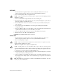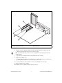
1
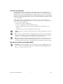
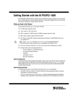
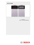
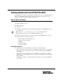
Getting Started with the NI PXI/PCIe-8231
The NI PXI/PCIe-8231 (NI 8231) is a Gigabit Ethernet (GigE) interface device for the PXI, PCI Express
(PCIe), or CompactPCI bus. This document describes how to install and configure the necessary
hardware and software components to begin using the NI 8231.
What You Need to Get Started
You need the following items to set up and use the NI 8231.
❑ NI 8231 GigE interface device
❑ GigE Vision Camera
❑ Ethernet cable
❑ PXI, PCIe, or CompactPCI computer running Microsoft Windows Vista/2000/XP with at least
one available slot
Note Visit ni.com/info and enter rdvisionvista for more information about
National Instruments interface device compatibility with Windows Vista.
❑ NI Vision Acquisition Software 8.2.1 or later, which includes the NI-IMAQdx driver software
❑ Optional software for developing applications:
–
NI Vision Builder for Automated Inspection
–
NI Vision Development Module
–
LabVIEW
–
LabWindows™/CVI™
–
Microsoft Visual Basic
Related Documentation
The following documents contain additional information that you may find helpful:
•
NI Vision Acquisition Software Release Notes—Outlines new functionality, system requirements,
installation procedures, and descriptions of the documentation included with the NI-IMAQdx
driver software.
•
Measurement & Automation Explorer Help for NI-IMAQdx—Describes how to configure the
NI-IMAQdx driver software, NI interface devices, and cameras using Measurement & Automation
Explorer (MAX).
•
NI-IMAQdx User Manual—Contains fundamental programming concepts for the NI-IMAQdx
driver software
Safety Information
Caution
The following paragraphs contain important safety information you must follow when
installing and operating the device.
Do not operate the device in a manner not specified in the documentation. Misuse of the device may
result in a hazard and may compromise the safety protection built into the device. If the device is
damaged, turn it off and do not use it until service-trained personnel can check its safety. If necessary,
return the device to National Instruments for repair.
Keep away from live circuits. Do not remove equipment covers or shields unless you are trained to do
so. If signal wires are connected to the device, hazardous voltages can exist even when the equipment is
turned off. To avoid a shock hazard, do not perform procedures involving cover or shield removal unless
you are qualified to do so. Disconnect all field power prior to removing covers or shields.
If the device is rated for use with hazardous voltages (>30 Vrms, 42.4 Vpk, or 60 Vdc), it may require a
safety earth-ground connection wire. Refer to the device specifications for maximum voltage ratings.
Because of the danger of introducing additional hazards, do not install unauthorized parts or modify the
device. Use the device only with the chassis, modules, accessories, and cables specified in the
installation instructions. All covers and filler panels must be installed while operating the device.
Do not operate the device in an explosive atmosphere or where flammable gases or fumes may be
present. Operate the device only at or below the pollution degree stated in the specifications. Pollution
consists of any foreign matter—solid, liquid, or gas—that may reduce dielectric strength or surface
resistivity. The following is a description of pollution degrees.
•
Pollution Degree 1—No pollution or only dry, nonconductive pollution occurs. The pollution has
no effect.
•
Pollution Degree 2—Normally only nonconductive pollution occurs. Occasionally, nonconductive
pollution becomes conductive because of condensation.
•
Pollution Degree 3—Conductive pollution or dry, nonconductive pollution occurs. Nonconductive
pollution becomes conductive because of condensation.
Clean the device and accessories by brushing off light dust with a soft, nonmetallic brush. Remove other
contaminants with a stiff, nonmetallic brush. The unit must be completely dry and free from
contaminants before returning it to service.
You must insulate signal connections for the maximum voltage for which the device is rated. Do not
exceed the maximum ratings for the device. Remove power from signal lines before connection to or
disconnection from the device.
Caution National Instruments measurement products may be classified as either Measurement
Category I or II. Operate products at or below the Measurement Category level specified in the
hardware specifications.
Measurement Category1: Measurement circuits are subjected to working voltages2 and transient
stresses (overvoltage) from the circuit to which they are connected during measurement or test.
Measurement Category establishes standardized impulse withstand voltage levels that commonly occur
1
2
Measurement Categories as defined in electrical safety standard IEC 61010-1.
Working voltage is the highest rms value of an AC or DC voltage that can occur across any particular insulation.
Getting Started with the NI PXI/PCIe-8231
2
ni.com
in electrical distribution systems. The following is a description of Measurement (Installation1)
Categories:
•
Measurement Category I is for measurements performed on circuits not directly connected to the
electrical distribution system referred to as MAINS2 voltage. This category is for measurements of
voltages from specially protected secondary circuits. Such voltage measurements include signal
levels, special equipment, limited-energy parts of equipment, circuits powered by regulated
low-voltage sources, and electronics.
•
Measurement Category II is for measurements performed on circuits directly connected to the
electrical distribution system. This category refers to local-level electrical distribution, such as that
provided by a standard wall outlet (e.g., 115 V for U.S. or 230 V for Europe). Examples of
Measurement Category II are measurements performed on household appliances, portable tools,
and similar products.
•
Measurement Category III is for measurements performed in the building installation at the
distribution level. This category refers to measurements on hard-wired equipment such as
equipment in fixed installations, distribution boards, and circuit breakers. Other examples are
wiring, including cables, bus-bars, junction boxes, switches, socket-outlets in the fixed installation,
and stationary motors with permanent connections to fixed installations.
•
Measurement Category IV is for measurements performed at the primary electrical supply
installation (<1,000 V). Examples include electricity meters and measurements on primary
overcurrent protection devices and on ripple control units.
Unpacking
The NI 8231 ships in an antistatic package to prevent electrostatic discharge from damaging device
components. To avoid such damage in handling the device, take the following precautions:
1.
Ground yourself using a grounding strap or by touching a grounded object, such as the computer
chassis.
2.
Touch the antistatic package to a metal part of the computer chassis before removing the device
from the package.
Caution
3.
Never touch the exposed pins of connectors.
Remove the device from the package and inspect it for loose components or any other signs of
damage. Notify National Instruments if the device appears damaged in any way. Do not install a
damaged device in the computer.
Store the NI 8231 in the antistatic package when not in use.
Installation
The following instructions are for general installation. Refer to the documentation provided by your
computer manufacturer for specific instructions and warnings. Refer to the Specifications section for a
list of the typical power requirements for the NI 8231.
1
2
Measurement Category is also referred to as Installation Category.
MAINS is defined as the (hazardous live) electrical supply system to which equipment is designed to be connected for the
purpose of powering the equipment. Suitably rated measuring circuits may be connected to the MAINS for measuring
purposes.
© National Instruments Corporation
3
Getting Started with the NI PXI/PCIe-8231
NI PXI-8231
1.
Install the NI Vision Acquisition Software before installing the NI PXI-8231. Refer to the
NI Vision Acquisition Software Release Notes for specific installation instructions.
2.
Power off and unplug the PXI or CompactPCI chassis.
Caution
To protect yourself from electrical hazards, the computer must remain unplugged until the
installation is complete.
3.
Choose an unused PXI or Compact PCI slot and remove the filler panel.
4.
Touch a metal part of the chassis to discharge any static electricity that might be on your clothes or
body. Static electricity can damage the device.
5.
Insert the NI PXI-8231 into the selected slot. Use the injector/ejector handle to fully inject the
device into place.
6.
Secure the front panel of the NI PXI-8231 to the front panel mounting rails of the PXI or
CompactPCI chassis.
7.
Connect the Ethernet cable to your camera. Refer to your camera manufacturer documentation for
specific instructions about how to connect the cable to your camera.
8.
Connect the Ethernet cable to the RJ-45 connector on the NI PXI-8231 front panel.
9.
Plug in and power on the PXI or CompactPCI chassis.
The NI PXI-8231 is installed and the camera is connected.
NI PCIe-8231
1.
Install the NI Vision Acquisition Software before installing the NI PCIe-8231. Refer to the
NI Vision Acquisition Software Release Notes for specific installation instructions.
2.
Power off and unplug the computer.
Caution
To protect yourself and the computer from electrical hazards, the computer must remain
unplugged until the installation is complete.
3.
Remove the computer cover to expose the expansion slots.
Caution Installing a PCIe device into a PCI, PCI-X, AGP, or any non-PCIe slot can damage both the
computer motherboard and the device. If you are unsure of the differences between the connector
types, do not install the device. Refer to the documentation provided by your computer manufacturer
to determine the correct slot in which to install the NI PCIe-8231.
4.
Touch a metal part of the computer to discharge any static electricity that might be on your clothes
or body. Static electricity can damage the device.
5.
Choose an unused x1 or larger PCIe slot, and remove the corresponding expansion slot cover on
the back panel of the computer. Figure 1 shows the different types of expansion slots available on
most computers.
Note The NI PCIe-8231 is intended for a x1 PCIe slot. The NI PCIe-8231 will fit into, and can be
used in, a x4, x8, or x16 PCIe slot.
Getting Started with the NI PXI/PCIe-8231
4
ni.com
1
2
3
4
1
2
PCI 32-bit Connector
PCI 64-bit and/or PCI-X Connector
3
4
PCIe x1 Connector
PCIe x16 Connector
Figure 1. PC Expansion Slots
6.
Remove your device from the antistatic package and gently rock the device into the slot. The
connection may be tight, but do not force the device into place.
Note Check that the bracket of your device lines up with the hole in the back panel rail of the
computer chassis.
7.
Secure the device mounting bracket to the back panel rail of the computer.
8.
Replace the computer cover.
9.
Connect the Ethernet cable to your camera. Refer to your camera manufacturer documentation for
specific instructions about how to connect the cable to your camera.
10. Connect the Ethernet cable to the RJ-45 connector on the NI PCIe-8231 front panel.
11. Plug in and power on the computer.
The NI PCIe-8231 is now installed and the camera is connected.
© National Instruments Corporation
5
Getting Started with the NI PXI/PCIe-8231
Configuring the NI 8231
After you have installed the NI 8231 and powered on your computer, Windows will recognize the device
and assign resources to it. Use Measurement & Automation Explorer (MAX), the National Instruments
configuration utility, to configure a GigE Vision compliant camera, connected to the NI 8231, for
acquisition. Refer to the Measurement and Automation Explorer Help for NI-IMAOdx for more
information about how to configure the NI 8231.
Note
Before configuring the device in MAX, ensure that you installed the NI-IMAQdx driver
software
Specifications
The following specifications apply to the NI 8231 interface device. These specifications are typical at
25 °C, unless otherwise stated.
Physical Characteristics
Dimensions
NI PXI-8231 ..................................................10.0 cm × 16.0 cm (3.9 in. × 6.3 in.)
NI PCIe-8231 .................................................12.9 cm × 12.0 cm (5.1 in. × 4.725 in.)
Camera Interface....................................................RJ-45
Weight
NI PXI-8231 ..................................................140 g (4.9 oz)
NI PCIe-8231.................................................70 g (2.5 oz)
Signaling
Ethernet..................................................................1000Base-T compliant on four pairs of
Category 5 cable
Power Requirements
NI PXI-8231
Typical............................................................788 mA at 3.3 V = 2.6 W maximum
1,330 mA at 3.3 V = 4.4 W maximum
NI PCIe-8231
Typical............................................................1 A at 3.3 V = 3.3 W maximum
375 mA at 3.3 Vaux = 1.24 W maximum
PCI Express Interface (NI PCIe-8231 Only)
PCI Express compliance ........................................Version 1.1
Native link width....................................................x1
Up-plugging link width availability.......................x4, x8, x16
Getting Started with the NI PXI/PCIe-8231
6
ni.com
Operating Environment
The NI 8231 is intended for indoor use only.
Ambient temperature range ...................................0 °C to 55 °C
Operating relative humidity
NI PXI-8231 ..................................................10% to 90%, noncondensing
NI PCIe-8231 .................................................50% to 85%, noncondensing
Pollution Degree ....................................................2
Caution
Do not use the NI 8231 for connection to signals within Measurement Categories II, III,
or IV.
Approved at altitudes up to 2,000 m.
Storage Environment
Ambient temperature range
NI PXI-8231 ..................................................–20 °C to 70 °C
NI PCIe-8231.................................................–40 °C to 70 °C
Relative humidity
NI PXI-8231 ..................................................5% to 95%, noncondensing
NI PCIe-8231 .................................................50% to 85%, noncondensing
Safety
This product is designed to meet the requirements of the following standards of safety:
•
IEC 60950-1, EN 60950-01
•
UL 60950-1, CSA 60950-1
Electromagnetic Compatibility
This product is designed to meet the requirements of the following standards of EMC for electrical
equipment for measurement, control, and laboratory use:
•
FCC Part 15—Radiated and Conducted Emissions (USA)
•
ICES-003—Radiated and Conducted Emissions (Canada)
•
CISPR 22—Radiated and Conducted Emissions (International)
•
EN55022—Radiated and Conducted Emissions (European Union)
•
EN55024—(Immunity) (European Union)
•
VCCI—Radiated and Conducted Emissions (Japan)
•
CNS13438—Radiated and Conducted Emissions (Taiwan)
•
AS/NZS3548—Radiated and Conducted Emissions (Australia/New Zealand)
•
MIC notice 1997-41, EMI and MIC notice 1997-42—EMS (Korea)
CE Compliance
This product meets the essential requirements of applicable European Directives, as amended for
CE marking, as follows:
•
73/23/EEC; Low-Voltage Directive (safety)
•
89/336/EEC; Electromagnetic Compatibility Directive (EMC)
© National Instruments Corporation
7
Getting Started with the NI PXI/PCIe-8231
FCC Class B User Information
This equipment has been tested and found to comply with the limits for the class B digital device
pursuant to Part 15 of the FCC rules. These limits are designed to provide reasonable protection against
harmful interference in a residential installation. The equipment generates, uses and can radiate radio
frequency energy and, if not installed and used in accordance with the instructions, may cause harmful
interference to radio communications. However, there is no guarantee that interference will not occur in
a particular installation.
If this equipment does cause harmful interference to television or radio reception, which can be
determined by turning the equipment off and on, the user is encouraged to try to correct the interference
by one or more of the following means:
•
Reorient or relocate the receiving antenna.
•
Increase the separation between the equipment and receiver.
•
Connect the equipment into an outlet on a circuit different from that to which the receiver is
connected.
•
Consult the dealer or an experienced radio/TV technician for help.
Caution If the device is changed or modified, the user may void his or her authority to operate the
equipment.
Note This device complies with Part 15 of the FCC Rules. Operation is subject to the following two
conditions: (1) this device may not cause harmful interference, and (2) this device must accept any
interference received, including interference that may cause undesired operation.
Note Refer to the Declaration of Conformity (DoC) for this product for any additional regulatory
compliance information. To obtain the DoC for this product, visit ni.com/certification,
search by model number or product line, and click the appropriate link in the Certification column.
Waste Electrical and Electronic Equipment (WEEE)
EU Customers At the end of their life cycle, all products must be sent to a WEEE recycling center.
For more information about WEEE recycling centers and National Instruments WEEE initiatives,
visit ni.com/environment/weee.htm.
Getting Started with the NI PXI/PCIe-8231
8
ni.com
Where to Go for Support
The National Instruments Web site is your complete resource for technical support. At ni.com/
support you have access to everything from troubleshooting and application development self-help
resources to email and phone assistance from NI Application Engineers.
A Declaration of Conformity (DoC) is our claim of compliance with the Council of the European
Communities using the manufacturer’s declaration of conformity. This system affords the user
protection for electronic compatibility (EMC) and product safety. You can obtain the DoC for your
product by visiting ni.com/certification. If your product supports calibration, you can obtain the
calibration certificate for your product at ni.com/calibration.
National Instruments corporate headquarters is located at 11500 North Mopac Expressway, Austin,
Texas, 78759-3504. National Instruments also has offices located around the world to help address
your support needs. For telephone support in the United States, create your service request at
ni.com/support and follow the calling instructions or dial 512 795 8248. For telephone support
outside the United States, contact your local branch office:
Australia 1800 300 800, Austria 43 662 457990-0, Belgium 32 (0) 2 757 0020,
Brazil 55 11 3262 3599, Canada 800 433 3488, China 86 21 5050 9800,
Czech Republic 420 224 235 774, Denmark 45 45 76 26 00, Finland 385 (0) 9 725 72511,
France 33 (0) 1 48 14 24 24, Germany 49 89 7413130, India 91 80 41190000, Israel 972 3 6393737,
Italy 39 02 413091, Japan 81 3 5472 2970, Korea 82 02 3451 3400, Lebanon 961 (0) 1 33 28 28,
Malaysia 1800 887710, Mexico 01 800 010 0793, Netherlands 31 (0) 348 433 466,
New Zealand 0800 553 322, Norway 47 (0) 66 90 76 60, Poland 48 22 3390150,
Portugal 351 210 311 210, Russia 7 495 783 6851, Singapore 1800 226 5886,
Slovenia 386 3 425 42 00, South Africa 27 0 11 805 8197, Spain 34 91 640 0085,
Sweden 46 (0) 8 587 895 00, Switzerland 41 56 2005151, Taiwan 886 02 2377 2222,
Thailand 662 278 6777, Turkey 90 212 279 3031, United Kingdom 44 (0) 1635 523545
© National Instruments Corporation
9
Getting Started with the NI PXI/PCIe-8231
National Instruments, NI, ni.com, and LabVIEW are trademarks of National Instruments Corporation. Refer to the Terms
of Use section on ni.com/legal for more information about National Instruments trademarks. Other product and
company names mentioned herein are trademarks or trade names of their respective companies. For patents covering
National Instruments products, refer to the appropriate location: Help»Patents in your software, the patents.txt
file on your CD, or ni.com/patents.
© 2006–2007 National Instruments Corporation. All rights reserved.
372082C-01
Mar07