1
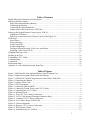
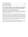
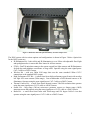
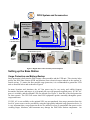
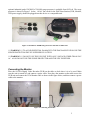
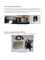
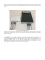
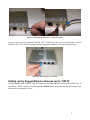
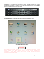
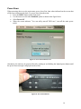
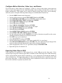
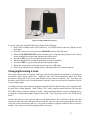
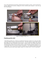
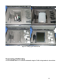
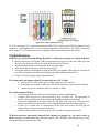
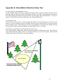
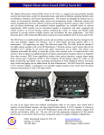
DIGITAL OBSERVATION GUARD
USER MANUAL
Version 1.13
July 25, 2012
0
Table of Contents
Digital Observation Guard System Description ....................................................................................... 2
Setting up the Base Station ....................................................................................................................... 4
Surge Protection and Battery Backup ................................................................................................... 4
Connecting the Monitor ........................................................................................................................ 5
Connecting the Alarm Button Box ....................................................................................................... 6
Setting up the Video Data Power (VPD) Unit ...................................................................................... 6
Setting up the Rugged Remote Cameras (up to 1500 ft) .......................................................................... 8
Alignment of Cameras ........................................................................................................................ 11
Removing a connection from a Remote Camera Unit (Figure 16) ..................................................... 12
DVR Setup .............................................................................................................................................. 12
Power Down ....................................................................................................................................... 14
Password Setting................................................................................................................................. 15
Set the Date/Time ............................................................................................................................... 15
Set Recording Mode ........................................................................................................................... 15
Configure Motion Detection, Video Loss, and Alarms ...................................................................... 16
Exporting Video Clips to DVD .......................................................................................................... 16
Changing/Focusing a Lens ..................................................................................................................... 17
Packing up the Unit ................................................................................................................................ 18
Terminating CAT-5 Cable ...................................................................................................................... 19
Troubleshooting ...................................................................................................................................... 20
Contact Info ............................................................................................................................................ 22
Replacement Parts .................................................................................................................................. 22
Appendix A: Video Motion Detection Setup Tips ................................................................................. 23
Table of Figures
Figure 1: DOG Base Kit with Optional Military Grade Transport Case .................................................. 3
Figure 2: Digital Observation Guard System and Options ....................................................................... 4
Figure 3: 120/240VAC 50/60Hz Surge Protector and 120VAC 60Hz UPS ............................................ 5
Figure 4: Connecting the Monitor ............................................................................................................ 5
Figure 5: Connect Alarm Cable ................................................................................................................ 6
Figure 6: VPD Components...................................................................................................................... 6
Figure 7: Connecting VPD and DVR ....................................................................................................... 7
Figure 8: Connecting Ground, Power, and CAT-5 Cables ....................................................................... 8
Figure 9: Connecting the CAT-5 Cables .................................................................................................. 8
Figure 10: Monitor Screen ........................................................................................................................ 9
Figure 11: Prep CAT-5 for Camera Connection....................................................................................... 9
Figure 12: CAT-5 Cable through Watertight Connector Body .............................................................. 10
Figure 13: Complete CAT-5 Camera Connection .................................................................................. 10
Figure 14: Live Camera Image on DVR Unit ........................................................................................ 11
Figure 15: Camera Alignment ................................................................................................................ 11
Figure 16: Remove CAT-5 Camera Connection .................................................................................... 12
Figure 17: DVR Interface Panel. ............................................................................................................ 13
Figure 18: Main Menu Screen - Labeled. ............................................................................................... 13
1
Figure 19: Power Down Menu Screen.................................................................................................... 14
Figure 20: Power Down Button .............................................................................................................. 14
Figure 21: Plug in USB Storage Device. ................................................................................................ 17
Figure 22: Changing//Focusing a Lens ................................................................................................... 18
Figure 23: Packing Up the DOG Base Kit.............................................................................................. 19
Figure 24: CAT-5 Termination Wiring .................................................................................................. 20
NOTE: THIS MANUAL SERVES AS A GUIDE TO RAPIDLY SETTING UP AND USING
THE DOG SYSTEM. SPECIFIC DETAILS OF DVR OPERATION ARE DEFERRED TO
THE ENCLOSED DVR USER MANUAL WHICH COMES PACKAGED WITH EACH KIT.
Digital Observation Guard System Description
The Digital Observation Guard (DOG) from S4 Tech is a rapidly deployable self-contained security
and surveillance system designed for the CENTCOM operational environment. The DOG is a
standalone security system that has been designed to be portable, rugged, cost effective, easy to install
in the field, and easy to maintain.
The DOG system consists of an H.264 Digital Video Recorder (DVR) unit capable of simultaneously
displaying live video, recording live video, and performing motion detection for the cameras in the
DOG system. The system takes power from any 100-240VAC 50/60Hz power source and distributes
video, power, and data signals to the remote rugged low-light camera units up to 1500ft away using
standard CAT-5 cable with standard connectors. This distribution is accomplished via the DOG Video
Power Data (VPD) unit and specialized circuitry at the remote cameras. The pan/tilt unit’s power and
control signals can also be sent over the same CAT-5 cable when this option is used. Video data is
collected, displayed, and recorded at the Digital Video Recorder (DVR) unit. Motion detection, user
triggered alarms, and storage parameters are all set up in the DVR menus.
Installation of the rugged low-light camera modules only requires mounting the module to a wall or
pole and connecting a single standard CAT-5 cable with an RJ-45 connector through the weather
resistant connector on the camera module. The DOG Base Kit is shown in Figure 1 below.
2
Figure 1: DOG Base Kit with Optional Military Grade Transport Case
The DOG system with its various options and configurations is shown in Figure 2 below. Option kits
for the DOG system are:
• IR Illuminator Kit - both visible and IR illumination to over 300m with adjustable flood light
and spotlight modes via removable filter lenses for all four cameras.
• PT Kit – Pan/Tilt units that connect to the remote rugged low-light cameras and IR illuminators
for both day and nighttime surveillance of large areas. Operates using the same signal/power
CAT-5 cable as a DOG Camera.
• Wireless Kit – with over 200m LOS range that uses the same standard 1500m CAT-5
connections as the standard DOG system.
• High Performance PTZ Kit – A small form factor high performance pan tilt unit with an ultra
low light 10X zoom camera (300m range). Can accommodate a DOG thermal camera or IR
illuminator. Operates using the same signal/power CAT-5 cable as a DOG Camera.
• Thermal Camera Kit – a small form factor thermal camera 320x240 resolution that operates
using the same signal/power CAT-5 cable as a DOG Camera.
• Sensor Kit – long range (300+m) microwave perimeter sensors or shorter range (100ft)
intrusion sensors that operate using the same signal/power CAT-5 cable as a DOG Camera.
• Radar Kit – a small form factor radar with 300m range and 120 degree field of view that
operates using the same signal/power CAT-5 cable as a DOG Camera.
3
DOG System and Accessories
Viewing and
Control Station
Location
100-240VAC
Power Supply
100-240VAC
Power Supply
Video/Power/Data
Distribution
Scambled Radio
w/ BA5590 Battery
PTZ Options
CAT5 Cable Video/Power/Data to 1500 ft
Radar
IR Illumination Options
Sensor/Camera Combo
Thermal
Camera
Figure 2: Digital Observation Guard System and Options
Setting up the Base Station
Surge Protection and Battery Backup
Surge protection is built into the DOG remote camera modules and the VPD unit. This circuitry helps
protect the DOG Base Station (DVR and Monitor) from electrical surges induced at the cameras or
outside wiring. To ensure the best possible surge protection, it is recommended to ground the VPD
unit as discussed below and as shown in Figure 8
In many locations and situations, the AC line power may be very noisy and exhibit frequent
brownouts, blackouts, and surges, as is frequently the case with generator supplied power. If 120V AC
power is available, and the optional UPS was ordered (See Figure 3), then this is the ideal protection
for that scenario. The UPS will ensure that DOG equipment operates smoothly throughout power
surges and losses.
If 120V AC is not available or the optional UPS was not purchased, then surge protection from the
local AC power source can be provided by using the high quality industrial surge protection device. It
is very important that a surge protection device be utilized in areas of questionable line power as the
resulting surges, blackouts, and brownouts may damage the DOG Base Station components. An
4
optional industrial grade 120/240VAC 50/60Hz surge protector is available from S4-Tech. The surge
protector is shown in Figure 3 below. All AC line cords for the DOG Base Station (DVR, Monitor,
VPD power supply) should be plugged into this device or a comparable unit.
Figure 3: 120/240VAC 50/60Hz Surge Protector and 120VAC 60Hz UPS
***WARNING*** TO AVOID POTENTIAL DAMAGE TO THE DOG BASE STATION USE THE
SURGE PROTECTION DEVICE SUPPLIED BY S4-TECH.
***WARNING*** DO NOT USE THE UPS UNIT WITH ANY VOLTAGE OTHER THAN 120V
AC. ALSO DO NOT USE THE SURGE PROTECTOR AND THE UPS TOGETHER.
Connecting the Monitor
Place the S4-Tech Digital Video Recorder (DVR) on the table or desk where it is to be used. Make
sure the unit is turned off, and connect a power cable. Next place the monitor on the table next to the
DVR unit and connect the VGA Monitor cable as shown in the figure below, and then connect a power
cable to the monitor.
Figure 4: Connecting the Monitor
5
Connecting the Alarm Button Box
The Alarm Button Box already secured on the DVR and connected with associated DB15 cable is
shown below. Plug one end of the DB-15 (Male-Male) cable to the mating connector on the back of
the DVR and the other end to the mating connector on the back of the Alarm Button Box. Tighten the
screws on the DB15 connectors to ensure that they do not come loose.
Figure 5: Connect Alarm Cable
Setting up the Video Data Power (VPD) Unit
Remove the silver VPD box, 4 coax cables, and power supply from the DOG packing case.
Figure 6: VPD Components
6
Place the silver VPD box within several feet of the DVR and connect the 4 BNC coax cables from the
BNC connectors on the VPD box to the appropriate BNC inputs on the back of the DVR as shown
below.
Figure 7: Connecting VPD and DVR
Plug the power supply into an outlet and connect to the VPD power input right next to the copper
grounding lug as seen in Figure 8 below. Power on the DVR via the button on the back panel above
the power cord input.
***WARNING*** TO AVOID POTENTIAL SHOCK OR DAMAGE FROM LIGHTNING IT IS
HIGHLY RECOMMENDED THAT THE GROUND LUG ON THE VPD BE CONNECTED TO A
GROUND SOURCE SUCH AS A PIPE OR LARGE METAL STRUCTURE, VIA A
REASONABLY LARGE (10-16 GAUGE) WIRE. THIS IS ESPECIALLY IMPORTANT IF THE
ELECTRICAL SYSTEM DOES NOT HAVE A SOLID GROUND.
7
Figure 8: Connecting Ground, Power, and CAT-5 Cables
Once the power has been connected and the CAT-5 cables have been run out to the Remote Camera
Modules, the CAT-5 cables are plugged into the appropriate channels as seen in the figure below.
Figure 9: Connecting the CAT-5 Cables
Setting up the Rugged Remote Cameras (up to 1500 ft)
At this point the DVR, monitor, VPD, and alarm box are setup and the monitor shows a blank view as
seen below. If this is not the view, then push the MODE button repeatedly until the split channel view
showing all four channels is seen.
8
Figure 10: Monitor Screen
The first step in setting up the remote camera modules is to run the CAT-5 cables from the VPD out to
each camera location. It is highly recommended that all cables and cameras are tested prior to
running your cables to the final installation point. This will help reduce work if a bad cable or
connector is found prior to the running of the cable. The CAT-5 cables should not exceed 1500ft for
optimum performance and should be UV resistant if they are going to be outdoors for prolonged
periods of time (months).
Once the camera modules have been mounted and the cable has been run, the connection at each
camera end is made. First prep the CAT-5 cable by removing any protective boots around the RJ-45
connector and adding several wraps of electrical tape (to help ensure a good seal) around the first few
inches of the cable as shown below.
Figure 11: Prep CAT-5 for Camera Connection
9
Once the CAT-5 cable end has been prepared, unscrew the bottom half of the waterproof connector on
the bottom of the remote camera module and pass the end of the CAT-5 cable through the connector as
shown below.
Figure 12: CAT-5 Cable through Watertight Connector Body
Plug the RJ-45 connector into the female RJ-45 receptacle inside the waterproof connector as shown in
Figure 13. Make sure that the RJ-45 tab lines up with the connector tab hole and that it snaps into
place inside the receptacle. Once this is done, screw the watertight connector cover back on and
tighten. Then strain relieve the CAT-5 cable by tightening the lower nut until the cable is snug inside
the connector.
Figure 13: Complete CAT-5 Camera Connection
Back at the DVR station, the CAT-5 cable for that camera can now be plugged into the VPD in the
corresponding channel.
10
*** WARNING*** IN ORDER TO PREVENT CAPACITIVE OVERLOADING OF THE POWER
SUPPLY, IT IS RECOMMENDED TO PLUG THE VIDEO CABLES INTO THE VPD ONE AT A
TIME WHILE THE VPD IS ALREADY POWERED UP. THIS IS ESPECIALLY IMPORTANT IF
THE CAT-5 CABLES ARE SHORTER THAN A FEW HUNDRED FEET.
Once this is done the camera image should show up on the DVR monitor screen as seen below.
Figure 14: Live Camera Image on DVR Unit
Alignment of Cameras
Camera alignment is accomplished by having a person at the camera loosen the thumb screw (as seen
in the first image of the figure below) on the tripod and move the camera around while a person
viewing the camera on the monitor communicates alignment instructions. If you have the optional
BNC viewing port and field monitor connect it up as seen in the second and third images. Once the
camera is aligned properly lock it down with the thumbscrew as seen in the first image.
Figure 15: Camera Alignment
11
Removing a connection from a Remote Camera Unit (Figure 16)
To remove the connection from a remote camera unit perform the following:
•
•
•
Loosen the lower waterproof connector nut until the cable is loose in the connector
Loosen the lower portion of the waterproof connector and remove from the main body
Put a screwdriver into the main body and push the RJ-45 tab up while simultaneously pulling
out the cord
Figure 16: Remove CAT-5 Camera Connection
DVR Setup
The DVR has been pre-configured at S4 for basic operation. After the DOG system is set up, the user
should read through the DVR manual and tune the motion detection and alarm parameters. Some basic
configuration information is provided below.
The DVR is configured via menu items that are presented by pressing the MENU button on the DVR
panel and using various other panel buttons to make selections. To select an item use the up and down
arrows to scroll the cursor to the item and then push the ENTER. Once the item is highlighted use the
up/down arrows to select a new value for the item. Once the proper value is displayed, push the
12
ENTER button to select the new value and finalize the change. The ESC button takes you one layer
up in the menu tree each time it is pushed. To access the DVR configuration screen, press the MENU
button on the DVR panel as seen in the figure below.
Figure 17: DVR Interface Panel.
Once the MENU button is pushed the main menu as seen below appears on the screen.
Figure 18: Main Menu Screen - Labeled.
WARNING
THE DVR SHOULD NOT BE POWERED OFF BY SIMPLY SHUTTING OFF POWER TO THE
DEVICE. PLEASE READ THE SECTION BELOW ON THE PROPER POWER-DOWN
PROCEDURE.
HARD DRIVE DAMAGE MAY OCCUR IF THE CORRECT SHUTDOWN
PROCEDURE IS NOT FOLLOWED.
13
Power Down
When powering down, use the main menu power down first, then when indicated on the screen shut
off the power button on the back. To power down from the menu:
• Press the MENU button on the front panel
• Use the arrows to select the Shutdown option as shown in the figure below
• Select Power Off
• When the screen indicates ”You can safely turn-off DVR now”, turn-off the main power
switch
Figure 19: Power Down Menu Screen.
Alternately, the unit may be powered down by pushing in and holding the lighted power button until
the power down message is displayed on the screen.
Figure 20: Power Down Button
14
Password Setting
Initially there is no password required to change settings on the DVR. If the system is reset to its
factory settings for some reason then the default password will be “1234”. To set a password do the
following:
•
•
•
•
•
•
•
Press MENU button on front panel
Use arrows to select SYSTEM SETUP with cursor and push ENTER
Select USER MANAGEMENT and then select PASSWORD PROTECTION
Select ON/OFF to enable or disable password based access.
Select ACCOUNT SETUP to configure accounts.
Select AUTHORITY SETUP to configure access levels.
Use ESC to move back up the menu hierarchy.
Set the Date/Time
To set the Date/Time of the unit:
• Press the MENU button on the front panel
• Use the arrows to select SYSTEM SETUP and press ENTER
• Select DATE/TIME SETUP and then press ENTER
• Select and assign the various parameters using the LEFT and RIGHT ARROWS to choose
options and the UP and DOWN ARROWS to change values.
• Use ESC to move back up the menu hierarchy
Set Recording Mode
The recording mode is used to set resolution and preset configuration. The recommended option that
gives a good mix of resolution and frames/sec for 4 cameras is 720 X 240 @ 60PPS. The default and
recommended mode is Event Based which means that only motion detection and user triggered events
will be stored.
***WARNING***
IN ORDER TO CHANGE THE RECORD MODE ALL EXISTING
RECORDED CLIPS WILL BE PURGED SO MAKE SURE THAT ALL DESIRED VIDEO CLIP
DATA HAS BEEN TRANSFERRED TO CD’S IF YOU HAVE ALREADY RECORDED VIDEO
AND PLAN TO CHANGE THE RESOLUTION.
To reset the recording mode to the recommended settings use the following steps:
•
•
•
•
•
•
•
•
Press the MENU button on the front panel
Use the arrows to select RECORD SETUP and press ENTER
Select RECORD SETUP MODE and then press ENTER
Select 720X240 @60PPS and press ENTER
Press ESC to go back up to RECORD MODE menu
Select PRESET CONFIG and press ENTER
Select EVENT ONLY and press ENTER
Use ESC to move back up the menu hierarchy
15
Configure Motion Detection, Video Loss, and Alarms
The Event menu is where alarms are configured. If there is a loss-of-video alarm, motion detection
alarm, or input alarm triggered by the Alarm Button Box, then recording to the hard drive of the event
begins automatically. These alarms can be turned off during system setup as they can be annoying.
Once the system is setup the following alarm settings are recommended for normal use:
•
•
•
•
•
•
•
•
•
•
•
•
•
•
•
•
•
•
•
Press the MENU button on the front panel
Use the up/down arrows to select EVENT SETUP and press ENTER
Select INTERNAL BUZZER and select ON/OFF to set the audio alarms.
Select PER CHANNEL CONFIG and then press ENTER
Select CHANNEL SELECT and press ENTER
Select CH1 and press ENTER
Select VIDEO LOSS DETECT and press ENTER
Select ON and press ENTER to detect loss of video input.
Select MOTION DETECT and press ENTER
Select ON and press ENTER
Select DETECTION CONFIG and press ENTER
Select DETECTED AREA SETUP and press ENTER
Use the up/down arrows and the ENTER key to create a detection area profile on the screen.
Anything outside the defined area will not be detected.
Press ESC to go up one menu layer
Select SENSITIVITY and press ENTER
Use the up/down arrows to select a value that is suitable (88% is a good start)
Select BLOCK THRESHOLD and press ENTER. This value represents the percentage of the
screen area that a detected object must occupy before an alarm is declared.
Select an appropriate value (3-5% is a good start) and press ZOOM/ENTER
Repeat this process for channels 2-4
Exporting Video Clips to DVD
Video clips may be exported to a USB storage device via the USB port on the front panel. If the
selected clips occupy more memory space than is available on the USB storage device then the backup
will be rejected and the process must be started over – so be conservative in selecting the number of
clips to be backed up. The figure below shows a USB stick and USB hard drive connected to the USB
port on the front panel. A USB CD/DVD burner with a standard device driver (does not require any
device driver software to operate) may also be used.
16
Figure 21: Plug in USB Storage Device.
To export clips to the installed USB storage media do the following:
• Insert USB recording media (stick, hard drive, or CD/DVD burner) into the USB port on the
back panel
• From the camera view screen, press the SEARCH button on the DVR panel
• Select the SEARCH EVENTS option and then select a clip and start playing it back. If there
are no recorded event clips in the unit then this will not work.
• Press the COPY key and it will mark the start of the export.
• When the playback has reached the point that you want to stop then:
• Press the COPY key again and it will mark the stop the export.
• Follow the screen menus to burn the selected export to USB media.
• If the export fails due to not enough memory start again and select a shorter segment
Changing/Focusing a Lens
The remote camera units are supplied with 3mm or 6mm lenses installed as indicated by a marking on
the bottom of the remote camera box. Additional 3mm and 12mm replacement lenses have been
provided to change the field of view and distance of two cameras as needed. The 3mm lens will
provide a wider field of view for short distances while the 12mm lens will provide a narrower field of
view for longer range.
To change a lens the camera must be plugged in near the DVR so that the image may be focused while
the new lens is being installed. With a short CAT-5 cable, plug the camera into the VPD near the
DOG Base Station so that the monitor is visible. Select the channel that the camera is plugged into by
pressing the corresponding number button on the DVR. This will put the camera view in full screen
mode.
Unscrew the end cap on the camera as shown in the figures below. Be careful not to tip the cap when
removed as there are some small parts that may fall out. Once the cap is removed, locate the set screw
in the rim of the camera body and use a very small screwdriver (supplied with DOG Kit) to loosen it
slightly. Now unscrew the lens by fingertip until it comes out.
17
Screw in the replacement lens and turn it until the picture on monitor is in focus. Once in its best focus
position, tighten the lens down by turning the set screw with the small screwdriver. Screw the cap
back on by fingertip.
Figure 22: Changing//Focusing a Lens
Packing up the Unit
The following pictures are a reference for packing the unit into its transport case. First pack all the
small items into the main bin on the bottom of the case. The DVR unit goes in upside down with the
feet sticking up on top of the bin that was just packed. It will rest on the cutout ledges. Next pack the
VPD and cameras into the right side cutouts as shown. Finally, put the cover over the bottom of the
VCR and place the monitor on top in the space that is formed. The standard DOG transport case is a
Contico model 1320. It is meant for one-time or infrequent use. For repeated transport under rough
conditions the optional military grade rugged transport case available from S4 Tech is recommended.
18
Figure 23: Packing Up the DOG Base Kit
Terminating CAT-5 Cable
It is recommended that CAT-5 cables be terminated using the T568B wiring standard as shown below.
19
Figure 24: CAT-5 Termination Wiring
S4 Tech can supply CAT-5 options that include 1000ft CAT-5e cable spools, EZRJ-45 crimp tools and
connectors, and stripping tools – see the Replacement Parts section below. The EZRJ-45 products
allow longer (2-4”) lead wires to be used, making the RJ45 connection process much easier.
Troubleshooting
DVR Boots Up and Freezes (Initializing Hard Drive or Database message) or Continuous Reboot
• Remove the top cover from the DVR by loosening the four screws on the side of the cover and
the one screw at the top of the cover at the back end of the DVR unit.
• Disconnect the hard drive cable from the back of the hard drive.
• Boot the DVR back up and see if the issue is resolved.
• If resolved then you can temporarily operate the DOG unit without a hard drive (It will provide
live video and motion detection, but recording is disabled without the hard drive).
• Contact S4 Tech for replacement of the hard drive.
The Camera does not operate when first connected to the CAT-5 cable:
• Test the CAT-5 cable with a tester or other camera to see if it is bad.
• If the cable tests ok then visually check the RJ-45 connector on the camera for damage
• Contact S4 Tech is neither the cable or connector is faulty.
The Camera Image is Blurry.
• Visually inspect the camera lens for external dust or internal condensation.
• If there is dust on lens, use a lint free cloth or wipe to clean it off. The application of
RAIN-X water repellant may help minimize frequent dust collection on the lens.
• If internal condensation is present loosen the end cap of the camera 5 turns and leave
camera powered on for several hours. Once condensation has burned off then retighten.
• If there is no visible dust or condensation on the lens, then refocus the lens per the
Change/Focus Lens procedure described above.
• If none of these actions work, then send in camera module for repair/replacement
VPD does not power up properly when all four cameras are plugged in – the video is noisy or
black. Unplug all remote camera units and power up the VPD. With the VPD still powered on, plug
the remote cameras back in one at a time.
20
Video image comes and goes on the monitor. Try moving the CAT-5 cable around near the
connectors on both the camera end and the base station end. If the video fluctuates with the cable
movement then the cable is going bad or a connection is loose.
Unit freezes up when video is played back. Internal video board may have gotten loose, especially if
the unit has been under rough transport conditions. Contact S4 Tech for how to reseat the board.
I get motion alarms for no reason every 15 to 30 seconds. It has been observed on some DOG
DVR’s that having a Sequence Call Monitor Schedule enabled can cause false motion detection events.
To remedy this problem the following procedure should be followed:
•
•
•
•
•
•
•
Press the MENU button on the front panel
Use the up/down arrows to select SEQUENCE SETUP and press ZOOM/ENTER
Use the up/down arrows to select
CALL MONITOR DWELL and then press
ZOOM/ENTER
Use the up/down arrows to select 120Sec and press ZOOM/ENTER
Use the up/down arrows to select CALL MONITOR SCHEDULE and press
ZOOM/ENTER
Use left arrow to delete all channels and press ZOOM/ENTER
Press ESC, ESC
When searching for an alarm clip the unit freezes up and the buttons on the front panel do not
respond. Sometimes a recorded event clip can be corrupted and it will cause the DVR to freeze up
when it enters the search window. The only current solution to this problem is to purge all the
recorded data. If there are important event clips on the DVR that are not on the same search screen as
the corrupted clip, then search them and burn them to a CD or USB stick. Then purge all data and start
over again.
•
•
•
Press the MENU button on the front panel
Use the up/down arrows to select RECORD SETUP and press ZOOM/ENTER
Select the PURGE DATA option and select ZOOM/ENTER
Some of the buttons on the front panel including the MENU button, do not respond when
pressed and there is a key shaped icon “
” near the bottom of the screen. This indicates that
the front panel has been locked. To unlock the front panel simply press and hold down the ESC button
on the front panel until the icon disappears from the bottom of the screen.
The camera images are dark even though it is not very dark outside. Turn up the brightness on the
monitor for each affected camera until the picture improves. If the picture does not improve up to the
point that the image washes out, then it is too dark and some illumination is necessary.
• Press the MENU button on the front panel
• Select CAMERA SETUP select CHANNEL press ZOOM/ENTER to change
• use the UP/DOWN arrows to select the desired channel and then ZOOM/ENTER to set
• Select BRIGHTNESS, then ZOOM/ENTER then use the UP/DOWN arrows to adjust.
• Select ZOOM/ENTER to set new level and ESC repeatedly to exit the menus.
21
Some of the CAT-5 connectors on the Remote Camera Modules seem to be corroding. Make sure
the seal around the CAT-5 cable coming into the Remote Module is tight. Wrap tape around the cable
before tightening the connector if necessary to get a tight seal. If available, consider applying a
silicone based dielectric grease to the contacts for extra corrosion protection.
Contact Info
For questions or support please see our website at: www.s4-tech.com or contact:
[email protected], 703-467-9034
For user manual or other technical downloads go to the customer tab on the website and login with the
following: user: customer password: 2004-S4Tech
Replacement Parts
The following replacement parts may be ordered for the DOG Base Kit (prices do not include
shipping). Credit card orders are accepted. Please contact S4 Tech for order information.
Part No.
DB-RC-xxx
DB-DVR-250
DB-LCD-15
DB-VPD
DB-VPD-PS
DB-TC-F
DB-RCASE-v1
DB-C5S-1000
DB-EZ-TS
DB-SURGE-240
DB-LPCC
DB-VPC-100
Description
Rugged Remote Camera Module (xxx – 3mm, 6mm, 12mm)
DVR Unit with 250GB storage
LCD Monitor with 15” screen
Video Power Data (VPD) distribution unit.
Power supply for the VPD unit.
Transport Case with new foam inserts
Optional military grade heavy duty transport case
CAT-5e Cable 1000ft spool (outdoor grade)
CAT-5 EZRJ-45 termination set (tools & 50 connectors)
Industrial grade surge protection 120/240VAC 50/60Hz
Low profile color camera.
Video Power Cable (100ft) for low profile color camera
22
Appendix A: Video Motion Detection Setup Tips
Avoid Looking into High Brightness Areas
Do not point the camera at the sun or towards the locations where sunrise or sunset occur. Also do not
point the cameras at directly at where bright lights will turn on at night. The bright light from the sun
or artificial lighting will make the image wash out and may trigger video motion alarms. It is best to
point the camera downward and to capture the area of interest from above.
Use the Proper Lens
Select the lens (3.6mm, 6mm, or 12mm) such that the field of view of the lens just covers the area of
interest. If you are looking at a gate for example, then select a lens whose field of view just covers the
gate and entrance path. This will greatly increase your probability of detection as the intruder will fill
a larger portion of the viewing area than a lens whose field of view is a lot wider.
Exclude Objects that Flutter in the Wind from the Field of View
Trees, flags, banners, laundry lines, and other movable objects will flutter in the wind. This fluttering
causes motion detection alarms if they are within the field of view of a DOG camera. Please do not
include such objects in the field of view when sighting.
Lens field of view matches
area of interest
Area of Interest
Objects that flutter in wind are
excluded from field of view
23