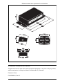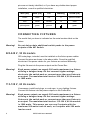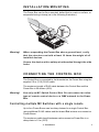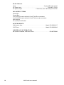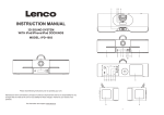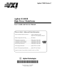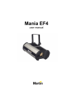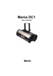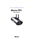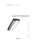
1
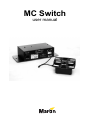
MC Switch
user manual
Measurements are expressed in millimeters.
75
258
155
120
114
78
323
355
50
102
143
109
© 2004 Martin Professional A/S, Denmark.
All rights reserved. No part of this manual may be reproduced, in any form or by any means,
without permission in writing from Martin Professional A/S, Denmark.
Printed in China.
P/N 35000141, Rev. D.
C ONTENTS
1. Introduction . . . . . . . . . . . . . . . . . . . . . . . . . . . . . . . . . . . . . . . . . . . . . . 1
Safety information . . . . . . . . . . . . . . . . . . . . . . . . . . . . . . . . . . . . . . . . . . . . 1
Unpacking . . . . . . . . . . . . . . . . . . . . . . . . . . . . . . . . . . . . . . . . . . . . . . . . . . 2
2. Installation . . . . . . . . . . . . . . . . . . . . . . . . . . . . . . . . . . . . . . . . . . . . . . . . 3
AC power . . . . . . . . . . . . . . . . . . . . . . . . . . . . . . . . . . . . . . . . . . . . . . . . . . . 3
Connecting fixtures . . . . . . . . . . . . . . . . . . . . . . . . . . . . . . . . . . . . . . . . . . . 4
Installation/mounting . . . . . . . . . . . . . . . . . . . . . . . . . . . . . . . . . . . . . . . . . . 5
Connecting the Control Box . . . . . . . . . . . . . . . . . . . . . . . . . . . . . . . . . . . . . 5
3. Operation . . . . . . . . . . . . . . . . . . . . . . . . . . . . . . . . . . . . . . . . . . . . . . . . . 6
4. Fuses . . . . . . . . . . . . . . . . . . . . . . . . . . . . . . . . . . . . . . . . . . . . . . . . . . . . . 7
115-120 V, 60 Hz model fuses. . . . . . . . . . . . . . . . . . . . . . . . . . . . . . . . . . . 7
220-240 V, 50 Hz model fuses. . . . . . . . . . . . . . . . . . . . . . . . . . . . . . . . . . . 7
Replacing the mains fuse. . . . . . . . . . . . . . . . . . . . . . . . . . . . . . . . . . . . . . . 7
5. Specifications . . . . . . . . . . . . . . . . . . . . . . . . . . . . . . . . . . . . . . . . . . . . 9
1. I NTRODUCTION
Thank you for selecting a Martin MC Switch. This switching device allows
you to turn on and off up to six devices.
The MC Switch is ruggedly built for years of trouble-free use. Setup and
operation are simple; please read this manual before setting up and
operating the device.
The MC Switch comes in two models:
• 220-240 V, 50 Hz
• 115-120 V, 60 Hz
The model that you have is indicated on the serial number label on the
fixture. An MC Switch consists of a Power Box and a Control Box (remote
control device).
SAFETY INFORMATION
Warning!
This product is not for household use. It presents risks of
lethal or severe injury due to fire and heat, electric shock, and
falls.
This product is for professional use only. It is not for household use. Read
this manual before powering or installing the fixture, follow the safety
precautions listed below and observe all warnings in this manual and
printed on the fixture. If you have questions about how to operate the
fixture safely, please contact your Martin dealer.
Note:
Ingress protection rating: IP 20
Switch for use in Class I Appliance
Number of operating cycles: 10000 times
Level 3 switch
Pollution degree 2
PTI 175
Rated impulse withstand voltage: 2500V
1. Introduction
1
Prot ecting yourself and others from electric shock
• Disconnect the fixture from AC power before removing or installing fuses
or any part, and when not in use.
• Always ground (earth) the fixture electrically.
• Use only a source of AC power that complies with local building and
electrical codes and has both overload and ground-fault protection.
• Do not expose the fixture to rain or moisture.
• Refer all service to a qualified technician.
• Never operate the fixture with missing or damaged covers.
Prot ecting yourself and others from burns and fire
• Never use the device to power fixtures that exceed the specified
maximum load.
• Never attempt to bypass the fuses.
• Always replace defective fuses with ones of the specified type and rating.
• Do not modify the fixture or install other than genuine Martin parts.
P rot ecti ng yo urself and o th ers fro m i nj ury du e to fall s
• When suspending the fixture above ground level, verify that the structure
can hold at least 10 times the weight of all installed devices.
• Secure the device with a safety wire threaded through the side holes.
• Block access below the work area whenever installing or removing the
fixture.
UNPACKING
The packing material is carefully designed to protect the fixture during
shipment - always use it to transport the fixture.
The MC Switch is packaged with the following:
•
•
•
•
Power Box
User manual
Six-button Control Box remote control unit
10-metre RJ-45 cable
220-240V, 50Hz models are also supplied with 2 earthed IEC power
cables and 6 IEC male plugs.
2
MC Switch user manual
2. I NSTALLATION
AC POWER
The MC Switch comes in two models:
• 220-240 V, 50 Hz
• 115-120 V, 60 Hz
The model that you have is indicated on the serial number label on the
fixture.
Warning
Do not operate the fixture on a power supply that falls outside
of these ranges.
Use only a source of AC power that complies with local
building and electrical codes and has both overload and
ground-fault protection.
For protection from dangerous electric shock, the fixture must
be grounded (earthed). The AC mains supply shall have
overload and ground-fault protection.
Important! Verify that the feed cables are undamaged and rated for the
current requirements of all connected devices before use.
The:
• 115-120 V model comes with a hard-wired 1-meter (3.3 ft) power cable.
• 220-240 V model comes with two 3-meter (10 ft) power cables - one
without a mains plug and the other with a 2-pin Euro plug.
Installing a plug on the mains lead
The MC Switch’s mains lead may require a grounding-type plug that fits
your power distribution cable or outlet. Consult a qualified electrician if
you have any doubts about proper installation.
Following the manufacturer’s instructions, install an approved groundingtype plug that fits your supply. Connect the wires to the pins as listed
below. The table shows some possible pin identification schemes; if the
2. Installation
3
pins are not clearly identified, or if you have any doubts about proper
installation, consult a qualified electrician.
Wire (EU)
Wire (US)
Pin
Marking
Screw (US)
brown
black
live
“L”
yellow or brass
blue
white
neutral
“N”
silver
yellow/green
green
ground
green
CONNECTING FIXTURES
The model that you have is indicated on the serial number label on the
fixture.
Warning!
Do not daisy-chain additional switch packs to the power
outputs of the MC Switch.
220-240 V, 50 Hz models
IEC male plugs, included, must be installed on the fixture power cables.
Connect the wires as shown in the above table. Consult a qualified
electrician if the power cables for your fixtures are colored differently.
Plug the fixtures into the power outputs on the Power Box.
Warning!
Each power output can supply 300 watts maximum to a fixture
utilizing a halogen lamp. Do not connect higher wattage
devices to the switch pack or connect more than one fixture to
an output. The maximum total load on 220-240 V, 50 Hz models
is 1800 watts.
115-120 V, 60 Hz models
If necessary, install local plugs, or cord caps, to your lighting fixtures.
Connect the fixtures into the power outputs on the Power Box.
Warning!
4
Each power output can supply 300 watts maximum to a fixture
utilizing a halogen lamp. Do not connect higher wattage
fixtures to the switch pack or connect more than one fixture to
an output. The maximum total load on 115-120 V, 60 Hz models
is 1500 watts. This means you can use 5 outputs with the
maximum 300 watts load on each, or 6 outputs with 250 watts
load on each.
MC Switch user manual
INSTALLATION/MOUNTING
The Power Box can be floor mounted, bolted fast to a rack or surface, or
suspended using a clamp (as in the following illustration).
M10
Warning!
When suspending the Power Box above ground level, verify
that the structure can hold at least 10 times the weight of all
installed devices.
Secure the device with a safety wire threaded through the side
holes.
CONNECTING THE CONTROL BOX
The Control Box is connected to the In socket on the Power Box using the
supplied 10 m (33 ft) RJ-45 cable.
The maximum length of RJ45 cable between the Control Box and the
Power Box is 20 meters (66 ft).
Warning!
Use only an MC Switch Control Box. Do not connect an other
type of remote control device or a DMX network to the Power
Box.
Controll ing mul tiple MC Swit c h e s w i t h a s i n gl e r e m ot e
Up to four Power Boxes can be daisy-chained to a single Control Box
using additional RJ-45 cables and the In and Out sockets on successive
Power Boxes.
The maximum cable length between each successive Power Box in a
daisy-chain is 10 m (33 ft).
2. Installation
5
3. OPERATION
Each of the six power outputs can be activated or deactivated using the
buttons on the Control Box. When power is on for an output the
associated LED will light up.
When controlling multiple Power Boxes with a single Control Box, each
button will activate or deactivate the associated power output on all the
Power Boxes.
6
MC Switch user manual
4. F USES
The MC Switch uses an onboard mains fuse for protection against current
overload. An indication that the fuse may have blown is that when power
is applied and the lamp is switched on, no light is produced.
If the fuse blows repeatedly, there is a fault with the unit that requires
service by a Martin technician.
Never bypass the fuse or replace it with one of another size or rating.
115-120 V, 60 HZ MODEL FUSES
The 115-120 V, 60 Hz model uses a 15AF mains fuse and six 4AT/250V
fuses (1 per power output):
15AF fuse . . . . . . . . . . . . . . . . . . . . . . . . . . . . . . . . . . . . . . . . Martin P/N 05021018
4AT fuse . . . . . . . . . . . . . . . . . . . . . . . . . . . . . . . . . . . . . . . . . Martin P/N 05020017
220-240 V, 50 HZ MODEL FUSES
The 220-240 V, 50 Hz model uses a 10AH mains fuse and six 2.5AT/250V
fuses (1 per power output):
10AH fuse . . . . . . . . . . . . . . . . . . . . . . . . . . . . . . . . . . . . . . . . Martin P/N 05021017
2.5AT fuse. . . . . . . . . . . . . . . . . . . . . . . . . . . . . . . . . . . . . . . . Martin P/N 05020010
REPLACING THE MAINS FUSE
1 Unplug the mains cable from the input socket.
4. Fuses
7
2 Open the fuse holder (located next to the mains power connector) with a
flat-head screwdriver and remove the fuse.
115-120V, 60Hz model
S
IN
A
M
T
U
P
IN
220-240V, 50Hz model
3 Replace the fuse with one of the same type. The fuse rating is listed on
the serial number label and in “5. Specifications” on page 9.
4 Replace the fuse cover.
8
MC Switch user manual
5. S PECIFICATIONS
115-120 V, 60 Hz version (U.S.)
PHYSICAL
Size - Power Box (LxWxH) . . . . . . . . . . . . . . . . . . 355x155x75 mm (14x6.1x32 in.)
Weight - Power Box . . . . . . . . . . . . . . . . . . . . . . . . . . . . . . . . . . . . . .1.85 kg (4 lbs)
CONSTRUCTION
Housing. . . . . . . . . . . . . . . . . . . . . . . . . . . . . . . . . . . . . . . . . . . . . . . . . . . . . . . steel
ELECTRICAL
AC Power input . . . . . . . . . . . . . . . . . . . . . . . . . . . . . . . . . . . . . . . 115-120 V, 60 Hz
AC power output . . . . . . . . . . . . . . . . . . . . 6 channels, max. total output 1500 watts
(250 watts per channel using 6 channels or
300 watts per channel using up to 5 channels)
INCLUDED ITEMS
Power Box
Control Box
2 m (6.5 ft) US mains cable 18AWG with US male connector (UL approved)
User manual
10 m (33 ft) RJ-45 cable
ACCESSORIES
15AF mains fuse . . . . . . . . . . . . . . . . . . . . . . . . . . . . . . . . . . Martin P/N 05021018
4AT fuse . . . . . . . . . . . . . . . . . . . . . . . . . . . . . . . . . . . . . . . . . Martin P/N 05020017
ORDERING INFORMATION
MC Switch 6 channel, 115-120V, 60Hz. . . . . . . . . . . . . . . . . . . . . . . P/N 90758245
220-240 V, 50 Hz version (E.U.)
PHYSICAL
Size - Power Box (LxWxH) . . . . . . . . . . . . . . . . . . 355x155x75 mm (14x6.1x32 in.)
Weight - Power Box . . . . . . . . . . . . . . . . . . . . . . . . . . . . . . . . . . . . . .1.85 kg (4 lbs)
CONSTRUCTION
Housing. . . . . . . . . . . . . . . . . . . . . . . . . . . . . . . . . . . . . . . . . . . . . . . . . . . . . . . steel
5. Specifications
9
ELECTRICAL
Input . . . . . . . . . . . . . . . . . . . . . . . . . . . . . . . . . . . . . . . . . 3-prong IEC male socket
AC Power input . . . . . . . . . . . . . . . . . . . . . . . . . . . . . . . . . . . . . . . 220-240 V, 50 Hz
AC power output . . . . . . . . . . . . . . . . . . . . 6 channels, max. 300 watts per channel
INCLUDED ITEMS
Power Box
Control Box
3 m (9.8 ft) EU mains cable 3x1.0mm2 with Euro connector
3 m (9.8 ft) EU mains cable 3x1.0mm2 with no male connector
User manual
10 m (33 ft) RJ-45 cable
ACCESSORIES
10AH mains fuse. . . . . . . . . . . . . . . . . . . . . . . . . . . . . . . . . . . Martin P/N 05021017
2.5AT fuse . . . . . . . . . . . . . . . . . . . . . . . . . . . . . . . . . . . . . . . . Martin P/N 05020010
ORDERING INFORMATION
MC Switch 6 channel, 220-240V, 50Hz. . . . . . . . . . . . . . . . . . . . . . . P/N 90758240
10
MC Switch user manual
www.martin.com • Olof Palmes Allé 18 • 8200 Aarhus N • Denmark
Tel: +45 8740 0000 • Fax +45 8740 0010