1
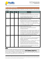
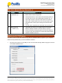
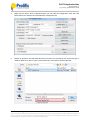
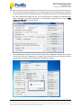
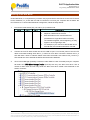
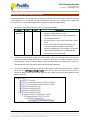
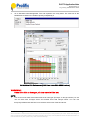
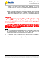
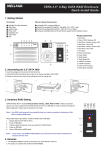
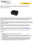
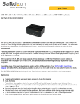
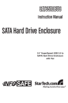
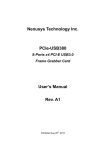
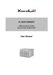
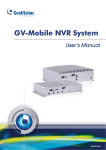
PL2775 Application Note Document Rev 1.0 an_PL2775_User Manual 20110307 Application Note PL2775 USB 3.0 to Dual SATA Bridge Controller User Manual (JBOD/BIG/RAID0/RAID1 Mode Features) Introduction The PL2775 is a low-power single-chip SuperSpeed USB 3.0 to Dual SATA II compliant bridge IC controller specially designed for external USB 3.0 dual-port RAID and non-RAID applications. It supports RAID 0 (striping) and RAID 1 (mirroring) as well as JBOD (Just a Bunch of Disks) and BIG (single logical disk) mode configurations. SuperSpeed USB has data transfer bandwidth of up to 5Gbps offering 10X performance increase over Hi-Speed USB (480Mbps). PL2775 JBOD / BIG / RAID0 / RAID1 Mode Application High Performance USB 3.0 to Dual SATA Storage Bridge Controller User-Switchable RAID0 (striping), RAID1 (mirroring), JBOD (Just a Bunch of Disks), and BIG mode configuration. Supports different capacity hard drives. USB 3.0 Specification and USB 2.0 Specification Compliant USB-IF SuperSpeed Logo Certified (TID No. 340740018) Serial ATA Revision 3.0 Specification Compliant Supports over 2TB and 4KB-sector Hard Drives Firmware update, Vendor/Product ID, and other related configuration information can be programmed to external Serial EEPROM or SPI serial flash through USB interface. Evaluation demo boards, PCB reference schematic, firmware, and software tools are all provided by Prolific for designing this application product. You can contact Prolific Sales or FAE for support. Getting Started This User Manual provides step-by-step installation and operating procedures on how to use the PL2775 USB 3.0 to Dual SATA enclosure. You would need the following: PL2775 Enclosure (for this manual, we will be using Prolific demo board) PL2775 Firmware File and RAID SDT File Prolific Storage MFG Kit Tool Software (for updating firmware) Two SATA Hard Drives (for RAID function, it is recommended to use two identical drives) Prolific Technology Inc. - 1 of 15 - March 7, 2011 All the information in this document is deemed to be correct but is subject to change without prior notice. Prolific Technology Inc. does not make any warranties (implied or otherwise) regarding the accuracy and completeness of this document and shall in no event be liable for any loss of profit or any other commercial damage. PL2775 Application Note Document Rev 1.0 an_PL2775_User Manual 20110307 PL2775 Demo Board Note the following PL2775 Demo Board connectors, button, jumpers, and LED locations. Please contact Prolific Sales or FAE for this demo board. PL2775 Demo Board LED Indicators and LED Behavior No. Features Descriptions 1 Power LED LED will turn ON when power supply and switch is ON. 2 SATA1 HDD LED LED will turn ON when PC detects SATA1 HDD. (GPIO P3_0) LED flashes when PC is accessing SATA1 HDD. SATA2 HDD LED LED will turn ON when PC detects SATA2 HDD. (GPIO P3_1) LED flashes when PC is accessing SATA2 HDD. For BIG mode, this LED will only flash when SATA1 HDD is 3 full or data is read/write from SATA2 HDD. 4 RAID Status Indicator (GPIO P1_0) This LED will flash 3 times @2Hz when switching between JBOD, BIG, RAID0, and RAID1 mode is successful. This LED is flashing along with P3_0 and P3_1 when RAID1 recovery is running. This LED will turn ON if there is an error in switch mode configuration or RAID1 recovery fails. See RAID1 section. 5 USB 3.0 LED Indicator (GPIO P1_5) Prolific Technology Inc. This LED will turn ON if PL2775 device is detected in USB 3.0 mode. Otherwise, this LED is OFF. - 2 of 15 - March 7, 2011 All the information in this document is deemed to be correct but is subject to change without prior notice. Prolific Technology Inc. does not make any warranties (implied or otherwise) regarding the accuracy and completeness of this document and shall in no event be liable for any loss of profit or any other commercial damage. PL2775 Application Note Document Rev 1.0 an_PL2775_User Manual 20110307 RAID Switch Mode Settings In order to switch between different mode configurations, you need to set the P3_4 and P3_5 switch as follows: Mode P3_4 P3_5 JBOD 1 1 Descriptions JBOD Mode: Just a Bunch of Drives Can support 1 or 2 SATA Drives. Each physical SATA Drive is independently addressed with all the logical partitions each may contain, being mapped to a different logical volume. BIG 0 1 BIG Mode: Concatenation or spanning of disks Requires 2 SATA Drives to work. Both SATA Drives are concatenated and presented as a single disk. Disks are merely concatenated together, end to beginning, so they appear to be a single large disk. For example, if you connect a 500 GB disk and a 250 GB disk, the total disk size will be 750 GB. RAID 0 1 0 (Striped) RAID 0 Mode: Striped Volume Requires 2 SATA Drives to work. Splits data evenly across two disks (striped) for increased performance. No data recovery. If one of the drives fails, all data is lost. If one of the drives has a smaller capacity, the total array size will be based on the smaller capacity multiplied by 2. For example, if a 120 GB disk is striped together with a 100 GB disk, the size of the array will be 200 GB. RAID 1 0 (Mirror) 0 RAID 1 Mode: Mirrored Volume Requires 2 SATA Drives to work. Creates an exact copy (or mirror) of data and partition on two disks. Total array size can only be as big as the smallest capacity drive. For example, if you connect a 120 GB disk and a 100 GB disk, the size of the array will only be 100 GB. Automatic data recovery if one of the drives fails and replaced with new drive. The new disk where the data to be recovered must be equal or greater than other disk; otherwise recovery is not possible. NOTE: After you have set the mode switch to your desired mode configuration, you will need to power off and power on the PL2775 demo board again while holding the RAID Switch Mode Button (P1_7) for more than 3 seconds. Afterwards, you will also need to repartition the drives to work properly. All data is lost after you switch to a different mode configuration. If you did not press the switch mode button, the PL2775 demo board will still remain in its last state mode. Prolific Technology Inc. - 3 of 15 - March 7, 2011 All the information in this document is deemed to be correct but is subject to change without prior notice. Prolific Technology Inc. does not make any warranties (implied or otherwise) regarding the accuracy and completeness of this document and shall in no event be liable for any loss of profit or any other commercial damage. PL2775 Application Note Document Rev 1.0 an_PL2775_User Manual 20110307 RAID Switch Mode & Backup Button (P1_7) No. 1 Features RAID Switch Mode Descriptions (GPIO P1_7) This button allows user to switch between JBOD, BIG, RAID0, RAID1 mode configuration. Press down button for more than 3 seconds when power on PL2775 demo board. Check RAID Status Indicator (P1_0) LED if flash 3 times to indicate mode switch successful. If LED is ON, it means there is an error and you need to check the RAID switch mode jumper settings and attached hard drives. 2 Prolific Backup You will need to repartition the drive after every mode switch. This button also serves as a trigger button for the Prolific (GPIO P1_7) Backup software installed on the PC while the PL2775 device is attached. Simply plug the PL2775 to the USB port of the PC and press the button to activate the Prolific Backup software installed on the PC. Updating the PL2775 Firmware You will first need to install the Prolific Storage MFG Kit EEPROM Editor program to your computer. Follow the steps below after you have installed the software: 1. Plug the PL2775 device to the USB port and run the Prolific Storage MFG Kit program and click on the EEP ROM Edit button. Prolific Technology Inc. - 4 of 15 - March 7, 2011 All the information in this document is deemed to be correct but is subject to change without prior notice. Prolific Technology Inc. does not make any warranties (implied or otherwise) regarding the accuracy and completeness of this document and shall in no event be liable for any loss of profit or any other commercial damage. PL2775 Application Note Document Rev 1.0 an_PL2775_User Manual 20110307 2. Make sure the device drive is detected before you can write the configuration. Click the Load EEP button first to load the PL2775 RAID SDT configuration file. 3. Browse to where the PL2775 RAID SDT file is located. You will need to first set the file type to “EEProm Data file (*.sdt)” in order to see the SDT file. Click Open to load the SDT file. Prolific Technology Inc. - 5 of 15 - March 7, 2011 All the information in this document is deemed to be correct but is subject to change without prior notice. Prolific Technology Inc. does not make any warranties (implied or otherwise) regarding the accuracy and completeness of this document and shall in no event be liable for any loss of profit or any other commercial damage. PL2775 Application Note Document Rev 1.0 an_PL2775_User Manual 20110307 4. Click on External Firmware Filename box to browse for the PL2775 firmware hex file. Browse to the folder where the PL2775 firmware hex file is located and click Open to load the firmware hex file. After loading the firmware hex file, you can also choose to configure the USB Descriptor Table according to your product description. If all configuration settings are done, click on Write configure & FW button to start the update. 5. The EEPROM Editor will then start to write the firmware and configuration settings. Do not power off the device until the configuration is complete. Click OK when finished and then reset the device power to activate the new firmware and configuration settings. Prolific Technology Inc. - 6 of 15 - March 7, 2011 All the information in this document is deemed to be correct but is subject to change without prior notice. Prolific Technology Inc. does not make any warranties (implied or otherwise) regarding the accuracy and completeness of this document and shall in no event be liable for any loss of profit or any other commercial damage. PL2775 Application Note Document Rev 1.0 an_PL2775_User Manual 20110307 Working under JBOD Mode Under JBOD Mode, you can attach either one or two physical SATA Hard Drives to the PL2775 demo board. To work under JBOD Mode configuration, follow the steps below: 1. First set the mode switch (P3_4=1 and P3_5=1) to JBOD mode. Mode P3_4 P3_5 JBOD 1 1 Descriptions JBOD Mode: Just a Bunch of Drives Can support 1 or 2 SATA Drives. Each physical SATA Drive is independently addressed with all the logical partitions each may contain, being mapped to a different logical volume. 2. Connect the PL2775 demo board into the PC USB 3.0 port. Turn ON the power of the PL2775 demo board while holding down the P1_7 button for more than 3 seconds. Observe the P1_0 LED will flash 3 times to indicate switch mode was successful. Also observe P3_0 and P3_1 LED should turn ON to indicate the SATA hard drives were detected. 3. Go to Device Manager (View By Connection under USB 3.0 Host Controller) and your computer will detect one USB Mass Storage Device (PL2775) with two SATA hard drives. 4. Go to Windows Disk Management Tool and repartition both disks. Each drive should be mapped to a different logical volume. Prolific Technology Inc. - 7 of 15 - March 7, 2011 All the information in this document is deemed to be correct but is subject to change without prior notice. Prolific Technology Inc. does not make any warranties (implied or otherwise) regarding the accuracy and completeness of this document and shall in no event be liable for any loss of profit or any other commercial damage. PL2775 Application Note Document Rev 1.0 an_PL2775_User Manual 20110307 JBOD HDD Performance (USB3 Host Under PCIe GEN2 Interface) Prolific Technology Inc. - 8 of 15 - March 7, 2011 All the information in this document is deemed to be correct but is subject to change without prior notice. Prolific Technology Inc. does not make any warranties (implied or otherwise) regarding the accuracy and completeness of this document and shall in no event be liable for any loss of profit or any other commercial damage. PL2775 Application Note Document Rev 1.0 an_PL2775_User Manual 20110307 Working under BIG Mode Under BIG Mode, it is required that you attach two physical SATA Hard Drives to the PL2775 demo board. Otherwise, P1_0 LED will turn ON to indicate an error and your computer will not detect the PL2775 device. To work under BIG Mode configuration, follow the steps below: 1. First set the mode switch (P3_4=0 and P3_5=1) to BIG mode. Mode P3_4 P3_5 BIG 0 1 Descriptions BIG Mode: Concatenation or spanning of disks Requires 2 SATA Drives to work. Both SATA Drives are concatenated and presented as a single disk. Disks are merely concatenated together, end to beginning, so they appear to be a single large disk. For example, if you connect a 500 GB disk and a 250 GB disk, the total disk size will be 750 GB. 2. Connect the PL2775 demo board into the PC USB 3.0 port. Turn ON the power of the PL2775 demo board while holding down the P1_7 button for more than 3 seconds. Observe the P1_0 LED will flash 3 times to indicate switch mode was successful. Also observe P3_0 and P3_1 LED should turn ON to indicate the SATA hard drives were detected. 3. Go to Device Manager (View By Connection under USB 3.0 Host Controller) and your computer will detect one USB Mass Storage Device (PL2775) with only one SATA hard drive. This is normal for BIG mode and will only show the SATA hard drive model name attached to the SATA1 connector. Prolific Technology Inc. - 9 of 15 - March 7, 2011 All the information in this document is deemed to be correct but is subject to change without prior notice. Prolific Technology Inc. does not make any warranties (implied or otherwise) regarding the accuracy and completeness of this document and shall in no event be liable for any loss of profit or any other commercial damage. PL2775 Application Note Document Rev 1.0 an_PL2775_User Manual 20110307 4. Go to Windows Disk Management Tool and repartition the concatenated disks. The total disk size of the disk is the sum of both disk capacities. BIG Mode HDD Performance (USB3 Host Under PCIe GEN2 Interface) NOTE: You must use two hard drives with same sector size type (512-byte or 4K-byte sectors). Do not use one drive with 512-byte sector and another drive with 4K-byte sector. You can use a third-party software like HDTune Pro to read the sector size of the hard drives. Prolific Technology Inc. - 10 of 15 - March 7, 2011 All the information in this document is deemed to be correct but is subject to change without prior notice. Prolific Technology Inc. does not make any warranties (implied or otherwise) regarding the accuracy and completeness of this document and shall in no event be liable for any loss of profit or any other commercial damage. PL2775 Application Note Document Rev 1.0 an_PL2775_User Manual 20110307 Working under RAID0 Mode (Striped) Under RAID0 Mode, it is required that you attach two physical SATA Hard Drives to the PL2775 demo board. Otherwise, P1_0 LED will turn ON to indicate an error and your computer will not detect the PL2775 device. To work under RAID0 Mode configuration, follow the steps below: 1. First set the mode switch (P3_4=1 and P3_5=0) to RAID0 mode. Mode P3_4 P3_5 RAID 0 1 0 (Striped) Descriptions RAID 0 Mode: Striped Volume Requires 2 SATA Drives to work. Splits data evenly across two disks (striped) for increased performance. No data recovery. If one of the drives fails, all data is lost. If one of the drives has a smaller capacity, the total array size will be based on the smaller capacity multiplied by 2. For example, if a 120 GB disk is striped together with a 100 GB disk, the size of the array will be 200 GB. 2. Connect the PL2775 demo board into the PC USB 3.0 port. Turn ON the power of the PL2775 demo board while holding down the P1_7 button for more than 3 seconds. Observe the P1_0 LED will flash 3 times to indicate switch mode was successful. Also observe P3_0 and P3_1 LED should turn ON to indicate the SATA hard drives were detected. 3. Go to Device Manager (View By Connection under USB 3.0 Host Controller) and your computer will detect one USB Mass Storage Device (PL2775) with only one SATA hard drive. This is normal for RAID0 mode and will only show the SATA hard drive model name attached to the SATA1 connector. Prolific Technology Inc. - 11 of 15 - March 7, 2011 All the information in this document is deemed to be correct but is subject to change without prior notice. Prolific Technology Inc. does not make any warranties (implied or otherwise) regarding the accuracy and completeness of this document and shall in no event be liable for any loss of profit or any other commercial damage. PL2775 Application Note Document Rev 1.0 an_PL2775_User Manual 20110307 4. Go to Windows Disk Management Tool and repartition the array disks. The total size of the RAID0 disk is based on the smaller capacity multiplied by 2. RAID0 Mode HDD Performance (USB3 Host Under PCIe GEN2 Interface) WARNING!!! If one drive fails or damages, all data stored will be lost. NOTE: You must use two hard drives with same sector size type (512-byte or 4K-byte sectors). Do not use one drive with 512-byte sector and another drive with 4K-byte sector. You can use third-party software like HDTune Pro to read the sector size of the hard drives. Prolific Technology Inc. - 12 of 15 - March 7, 2011 All the information in this document is deemed to be correct but is subject to change without prior notice. Prolific Technology Inc. does not make any warranties (implied or otherwise) regarding the accuracy and completeness of this document and shall in no event be liable for any loss of profit or any other commercial damage. PL2775 Application Note Document Rev 1.0 an_PL2775_User Manual 20110307 Working under RAID1 Mode (Mirror) Under RAID1 Mode, it is required that you attach two physical SATA Hard Drives to the PL2775 demo board. Otherwise, P1_0 LED will turn ON to indicate an error and your computer will not detect the PL2775 device. To work under RAID1 Mode configuration, follow the steps below: 1. First set the mode switch (P3_4=0 and P3_5=0) to RAID1 mode. Mode P3_4 P3_5 RAID 1 0 0 (Mirror) Descriptions RAID 1 Mode: Mirrored Volume Requires 2 SATA Drives to work. Creates an exact copy (or mirror) of data and partition on two disks. Total array size can only be as big as the smallest capacity drive. For example, if you connect a 120 GB disk and a 100 GB disk, the size of the array will only be 100 GB. Automatic data recovery if one of the drives fails and replaced with new drive. The new disk where the data to be recovered must be equal or greater than other disk; otherwise recovery is not possible. 2. Connect the PL2775 demo board into the PC USB 3.0 port. Turn ON the power of the PL2775 demo board while holding down the P1_7 button for more than 3 seconds. Observe the P1_0 LED will flash 3 times to indicate switch mode was successful. Also observe P3_0 and P3_1 LED should turn ON to indicate the SATA hard drives were detected. 3. Go to Device Manager (View By Connection under USB 3.0 Host Controller) and your computer will detect one USB Mass Storage Device (PL2775) with only one SATA hard drive. This is normal for RAID1 mode and will only show the SATA hard drive model name attached to the SATA1 connector. Prolific Technology Inc. - 13 of 15 - March 7, 2011 All the information in this document is deemed to be correct but is subject to change without prior notice. Prolific Technology Inc. does not make any warranties (implied or otherwise) regarding the accuracy and completeness of this document and shall in no event be liable for any loss of profit or any other commercial damage. PL2775 Application Note Document Rev 1.0 an_PL2775_User Manual 20110307 4. Go to Windows Disk Management Tool and repartition the array disks. Total array size can only be as big as the smallest capacity drive from the two drives attached. RAID1 Mode HDD Performance (USB3 Host Under PCIe GEN2 Interface) 5. RAID1 Mode offers automatic data recovery feature whenever one SATA drive fails while USB is connected to the computer. Note the following recovery steps: (1) Observe if RAID Status Indicator (P1_0) LED is ON and either SATA1 (P3_0) or SATA2 (P3_1) LED is OFF. This could mean one of the SATA drives is damaged. You can also use Prolific RAID Manager software to check the health status of both SATA drives. (2) While the PL2775 demo board is still connected to the PC and powered on, replace the damaged SATA drive with a new one. It is important that the PL2775 demo board is still Prolific Technology Inc. - 14 of 15 - March 7, 2011 All the information in this document is deemed to be correct but is subject to change without prior notice. Prolific Technology Inc. does not make any warranties (implied or otherwise) regarding the accuracy and completeness of this document and shall in no event be liable for any loss of profit or any other commercial damage. PL2775 Application Note Document Rev 1.0 an_PL2775_User Manual 20110307 powered on and detected by the PC when you replace the damaged drive. It is also important that the new SATA drive must be equal or greater than the size of the other working drive. Do not attempt to power off or unplug the USB cable when doing RAID data recovery. (3) When you attached a new SATA drive, automatic recovery will begin. Observe that the RAID Status Indicator will start to flash as well as the SATA1 (P3_0) and SATA2 (P3_1) LEDs. RAID1 recovery will take several hours to complete as it will mirror the entire partition of the other drive. IMPORTANT!! To do a RAID recovery on a new hard drive, you will need to replace the drive while the PL2775 demo board is still powered on and also connected to the computer. It is required that the new hard drive capacity should be equal or greater than the other hard drive. If you attempt to replace a new hard drive by first powering off the PL2775 demo board, the RAID1 function will not work properly unless you repartition the new RAID disk configuration. The PL2775 firmware also does not support RAID data recovery while disconnected from the computer. NOTES: You must use two hard drives with same sector size type (512-byte or 4K-byte sectors). Do not use one drive with 512-byte sector and another drive with 4K-byte sector. You can use third-party software like HDTune Pro to read the sector size of the hard drives. It is important that you do not power off the PL2775 demo board or let the computer go to sleep/hibernate while RAID1 data recovery is running. It is also best that you do not do any read/write on the PL2775 SATA drive during data recovery. Prolific Technology Inc. - 15 of 15 - March 7, 2011 All the information in this document is deemed to be correct but is subject to change without prior notice. Prolific Technology Inc. does not make any warranties (implied or otherwise) regarding the accuracy and completeness of this document and shall in no event be liable for any loss of profit or any other commercial damage.