1
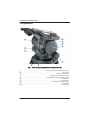
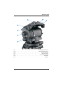
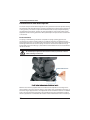
Vector 430 Pan and Tilt Head V4006-0001 Operators Guide V4006-4980/B Vector 430 Pan & Tilt Head Publication Part No.V4006-4980 Issue 1 July 2010 Published by Vitec Group Videocom Division Technical Publications Department William Vinten Building Western Way Bury St Edmunds Suffolk IP33 3TB UK Email: [email protected] Copyright © Vitec Group plc 2010 All rights reserved throughout the world. No part of this document may be stored in a retrieval system, transmitted, copied or reproduced in any way including, but not limited to, photocopy, photograph, magnetic or other record without the prior agreement and permission in writing of Vitec Group plc. Trademark Acknowledgements Vinten® is a registered trademark of Vitec Group plc. Disclaimer Camera Dynamics Limited reserves the right, without notice, to revise this documentation and make changes in content from time to time without obligation to provide notification of such revision or change. Revised documentation may be obtainable from Vinten or downloadable from the website (www.vinten.com). Camera Dynamics Limited reserves the right, without notice, to make changes in equipment design or performance as progress in engineering, manufacturing or technology may warrant. Operators guide Safety - read this first Understanding these instructions Eesti Käesoleva kasutajajuhendi algtekst on koostatud inglise keeles ning seejärel tõlgitud teistesse keeltesse. Kui juhend osutub teie jaoks arusaamatuks, võtke juhendi emakeelse tõlke hankimiseks ühendust Vinteni või kohaliku esindajaga (Euroopa Liidu riigid). English The original instructions presented in this operators guide were written in English, and subsequently translated into other languages. If you are unable to understand these instructions, contact Vinten or your distributor to obtain a translation of the original instructions (EU Countries). &' *+/'57< =>?MQX< *YZ=[ Z=Y =>?M=[ M'* Z= /X'+'\Z] \Y^Z`/x?5*^ \Z* {MM|'5` 5*' }XZ*~+`\Z?5*^ \Z? \Y^7/X'* \X `||X< M|\\X<. `^ >Y\5=|X[X\ZX ^* 5*Z*|`XZX *YZ7< Z'< =>?MQX<, X'5='^^]\ZX }X Z? Vinten ] Z= >'*^=}7* \*< M'* ^* |`XZX }'* }XZ`~+*\? Z^ *+/'5^ =>?M'^ (+X< ). , , , - . , Vinten , ( !). Español Las instrucciones originales que se indican en esta guía del operador se han redactado en inglés y posteriormente se han traducido a otros idiomas. Si no entiende estas instrucciones, póngase en contacto con Vinten o con su distribuidor para obtener una traducción de las instrucciones originales (para países de la UE). esky Pokyny uvedené v této operátorské p"íru#ce byly p$vodn% napsány anglicky a následn% byly p"elo_eny do ostatních jazyk$. Nerozumíte-li t%mto pokyn$m, kontaktujte spole#nost Vinten nebo svého distributora, abyste získali p"eklad originálních pokyn$ (#lenské státy EU). Français De originale instruktioner, der præsenteres i denne betjeningsvejledning, er skrevet på engelsk og derefter oversat til andre sprog. Hvis du ikke forstår disse instruktioner bedes du kontakte Vinten eller vor forhandler for at få en oversættelse af de originale instruktioner (EU-lande). Gaeilge Les instructions originales présentées dans ce guide d'utilisation ont été écrites en anglais puis traduites dans d'autres langues. Si vous ne comprenez pas ces instructions, contactez Vinten ou votre revendeur pour obtenir une traduction des instructions originales (pour les pays de l'UE). Danish Scríobhadh na treoracha bunaidh don treoirleabhar oibritheora seo as Béarla, agus aistríodh iad go teangacha eile ina dhiaidh sin. Mura bhfuil tú in ann na treoracha seo a thuiscint, téigh i dteagmháil le Vinten nó le do dháileoir, chun aistriúchán de na treoracha bunaidh a fháil (Tíortha an AE). Deutsch Die Originalanleitung in diesem Bedienungshandbuch wurde auf Englisch verfasst und anschließend in andere Sprachen übersetzt. Bei Verständnisproblemen in einer der übersetzten Sprachen kontaktieren Sie bitte Vinten oder Ihren Fachhändler; dort erhalten Sie eine Übersetzung der ursprünglichen Anleitung (EU-Staaten). Italiano Le istruzioni originali presentate in questa guida per l'operatore sono in lingua inglese e successivamente tradotte nelle altre lingue. Qualora le istruzioni non fossero disponibili nella lingua desiderata, potete contattare Vinten o il vostro distributore per ricevere la traduzione delle istruzioni originali (Paesi UE). 3 Vector 430 pan and tilt head Latviešu Português As instruções originais apresentadas no guia do operador foram escritas em Inglês e traduzidas para outros idiomas. Se não conseguir compreender estas instruções contacte a Vinten ou o seu distribuidor para obter a tradução das instruções originais (Países da UE). Šaj operatora rokasgrmat iekautie nordjumi skotnji tika sarakstti angu valod un pc tam prtulkoti cits valods. Ja nesaprotat šos nordjumus svešvalod, sazinieties ar Vinten vai tirgotju, lai saemtu nordjumu tulkojumu (kd no ES dalbvalstu valodm). Român Lietuvi Šiame operatoriaus vadove pristatomos pirmins instrukcijos parašytos angl kalba ir vliau išverstos kitas kalbas. Jei ši instrukcij nesuprantate, susisiekite su „Vinten“ arba savo platintoju ir gaukite pirmini instrukcij vertim (ES šalies kalba). Instruciunile originale prezentate în acest ghid pentru operatori au fost scrise în limba englez, i traduse ulterior în alte limbi. În cazul în care nu înelegei aceste instruciuni, contactai Vinten sau distribuitorul dumneavoastr pentru a obine o traducere a instruciunilor originale (rile UE). Slovensky Pôvodné pokyny, uvedené v tomto návode na obsluhu, boli napísané v anglictine a následne preložené do iných jazykov. Ak nerozumiete týmto pokynom, obrátte sa na spolocnost Vinten alebo vášho distribútora, aby vám zaslal preklad originálnych pokynov (krajiny EÚ). Magyar A kezeloi útmutatóban található utasítások angol nyelven íródtak, és utólag fordították azokat más nyelvekre. Ha nem érti ezen utasításokat, kérjük, vegye fel a kapcsolatot a Vintennel vagy a helyi képviselettel, és igényelje az eredeti utasítások fordítását (EU országok). Slovenšina Originalno besedilo teh navodil za uporabo je bilo napisano v angleš#ini in prevedeno v ostale jezike. ¡e ne razumete teh navodil, se obrnite na podjetje Vinten ali lokalnega zastopnika, ki vam bo posredoval originalna navodila (velja za dr_ave EU). Malti L-istruzzjonijiet originali ippreentati f'din il-gwida ta' operaturi kienu miktuba bl-Ingli, u sussegwentement maqluba fllingwi ohra. Jekk ma tistax tifhem dawn l-istruzzjonijiet, ikkuntattja lil Vinten jew id-distributur tieghek biex tikseb traduzzjoni ta' listruzzjonijiet originali (Pajjii ta' UE). Suomi Tähän käyttäjän oppaaseen sisältyvät ohjeet on kirjoitettu alun perin englanniksi ja käännetty sitten muille kielille. Ellet ymmärrä näitä ohjeita, ota yhteyttä Vinteniin tai jälleenmyyjään ja pyydä alkuperäisten ohjeiden käännöstä (EU-maat). Nederlands De oorspronkelijke instructies in deze bedieningshandleiding zijn geschreven in het Engels en vervolgens in andere talen vertaald. Als het onmogelijk is deze instructies te begrijpen, neemt u contact op met Vinten of met uw distributeur om een vertaling te bemachtigen van de oorspronkelijke instructies (EGlanden). Polski Oryginalne instrukcje zamieszczone w niniejszym podrczniku operatora zostay napisane w jzyku angielskim, a nastpnie przetumaczone na inne jzyki. Jeli nie rozumiej Pastwo tych instrukcji, prosimy skontaktowa si z siedzib lub dystrybutorem Vinten, aby uzyska tumaczenie oryginalnych instrukcji (kraje UE). 4 Svenska Instruktionerna i denna handbok skrevs ursprungligen på engelska och har sedan översatts till flera språk. Om du inte förstår dessa instruktioner, kontakta Vinten eller din återförsäljare för en ny översättning av originalinstruktionerna (EU-länder). Operators guide Warning Symbols in this Operators Guide Where there is a risk of personal injury or injury to others, comments appear highlighted by the word WARNING!—supported by the warning triangle symbol. Where there is a risk of damage to the product, associated equipment, process or surroundings, comments appear highlighted by the word CAUTION! Disposal of waste batteries Any batteries included with this product must not be treated as household waste. By ensuring these batteries are disposed of correctly, you will help prevent potentially negative consequences for the environment and human health, and help conserve natural resources. Please view the section on how to remove the batteries from the product safely. Hand the batteries over to the applicable collection point for recycling waste batteries. Usage The Vector 430 pan and tilt head is designed for use by professional camera operators working with full facility studio and OB cameras. The Vector 430 pan and tilt head can support and balance a camera system weighing up to 43 kg (94.8 lb). It is important that the head is mounted onto equipment designed to support the head and its maximum payload. Warning! 1. Do NOT attempt to use this product if you do not understand how to operate it. 2. Do NOT use this product for any other purpose than that specified in this Usage statement. 3. Maintenance beyond that detailed in this Operators Guide must be performed only by competent personnel. 5 Vector 430 pan and tilt head Technical specification Height . . . . . . . . . . . . . . . . . . . . . . . . . . . . . . . . . . . . . . . . . . . . . . . . . . . . . . . . . 208 mm (8.1 in.) Length . . . . . . . . . . . . . . . . . . . . . . . . . . . . . . . . . . . . . . . . . . . . . . . . . . . . . . . . 200 mm (7.8 in.) Width . . . . . . . . . . . . . . . . . . . . . . . . . . . . . . . . . . . . . . . . . . . . . . . . . . . . . . . . 285 mm (11.2 in.) Weight . . . . . . . . . . . . . . . . . . . . . . . . . . . . . . . . . . . . . . . . . . . . . . . . . . . . . . . . 10.4 kg (22.9 lb) Temperature range . . . . . . . . . . . . . . . . . . . . . . . . . . . . . . . . -40°C to +60°C (-40° F to +140° F) Tilt range. . . . . . . . . . . . . . . . . . . . . . . . . . . . . . . . . . . . . . . . . . . . . . . . . . . . . . . . . . . . . . . . ±90° Pan range . . . . . . . . . . . . . . . . . . . . . . . . . . . . . . . . . . . . . . . . . . . . . . . . . . . . . . . . . . . . . . 360° Typical Payload @ 150 mm CofG . . . . . . . . . . . . . . . . . . . . . . . . . . . . . . 10-43 kg (22 -94.8 lb) Pedestal/tripod fixing . . . . . . . . . . . . . . . . . . . . Four hole flat base with integral Quickfix groove . . . . . . . . . . . . . . . . . . . . . . . . . . . . . . . . . . . . . . . . . . . . . . . . . . . . . . . . . . . . . . Mitchell adaptor Adaptor. . . . . . . . . . . . . . . . . . . . . . . . . . . . . . . . . . . . . . . . . . . . . . . . . . . . EFP Quickfit adaptor Levelling bubble . . . . . . . . . . . . . . . . . . . . . . . . . . . . . . . . . . . . . . . . . . . . . . . . . illuminated, blue Pan bar. . . . . . . . . . . . . . . . . . . . . . . . . . . . . . . . . . . . . . . . . . . . . . . . . . . . . . . .single telescopic 6 Operators guide Contents Page Safety - read this first. . . . . . . . . . . . . . . . . . . . . . . . . . . . . . . . . . . . . . . . . . . . . . 3 Technical specification . . . . . . . . . . . . . . . . . . . . . . . . . . . . . . . . . . . . . . . . . . . . 6 Components . . . . . . . . . . . . . . . . . . . . . . . . . . . . . . . . . . . . . . . . . . . . . . . . . . . . . 8 Introduction and description. . . . . . . . . . . . . . . . . . . . . . . . . . . . . . . . . . . . . . . 10 Perfect balance . . . . . . . . . . . . . . . . . . . . . . . . . . . . . . . . . . . . . . . . . . . . . . . . . . . . . . . 10 Digital numeric display . . . . . . . . . . . . . . . . . . . . . . . . . . . . . . . . . . . . . . . . . . . . . . . . . . 11 TF drag . . . . . . . . . . . . . . . . . . . . . . . . . . . . . . . . . . . . . . . . . . . . . . . . . . . . . . . . . . . . . 11 Pan and tilt brakes . . . . . . . . . . . . . . . . . . . . . . . . . . . . . . . . . . . . . . . . . . . . . . . . . . . . . 12 Illuminated level bubble . . . . . . . . . . . . . . . . . . . . . . . . . . . . . . . . . . . . . . . . . . . . . . . . . 12 Four-hole mounting base . . . . . . . . . . . . . . . . . . . . . . . . . . . . . . . . . . . . . . . . . . . . . . . . 12 Pan bar . . . . . . . . . . . . . . . . . . . . . . . . . . . . . . . . . . . . . . . . . . . . . . . . . . . . . . . . . . . . . 12 EFP quickfit adaptor. . . . . . . . . . . . . . . . . . . . . . . . . . . . . . . . . . . . . . . . . . . . . . . . . . . . 12 Carrying handle . . . . . . . . . . . . . . . . . . . . . . . . . . . . . . . . . . . . . . . . . . . . . . . . . . . . . . . 12 Operation . . . . . . . . . . . . . . . . . . . . . . . . . . . . . . . . . . . . . . . . . . . . . . . . . . . . . . 13 Mounting the head . . . . . . . . . . . . . . . . . . . . . . . . . . . . . . . . . . . . . . . . . . . . . . . . . . . . . 13 Locking the platform. . . . . . . . . . . . . . . . . . . . . . . . . . . . . . . . . . . . . . . . . . . . . . . . . . . . 14 Pan and tilt brakes . . . . . . . . . . . . . . . . . . . . . . . . . . . . . . . . . . . . . . . . . . . . . . . . . . . . . 14 Fitting the pan bar . . . . . . . . . . . . . . . . . . . . . . . . . . . . . . . . . . . . . . . . . . . . . . . . . . . . . 14 Fitting a camera and payload. . . . . . . . . . . . . . . . . . . . . . . . . . . . . . . . . . . . . . . . . . . . . 15 Adjusting the slide plate . . . . . . . . . . . . . . . . . . . . . . . . . . . . . . . . . . . . . . . . . . . . . . . . . 16 Balancing the head . . . . . . . . . . . . . . . . . . . . . . . . . . . . . . . . . . . . . . . . . . . . . . . . . . . . 17 Transportation . . . . . . . . . . . . . . . . . . . . . . . . . . . . . . . . . . . . . . . . . . . . . . . . . . . . . . . . 19 Maintenance . . . . . . . . . . . . . . . . . . . . . . . . . . . . . . . . . . . . . . . . . . . . . . . . . . . . 20 General . . . . . . . . . . . . . . . . . . . . . . . . . . . . . . . . . . . . . . . . . . . . . . . . . . . . . . . . . . . . . 20 Routine maintenance . . . . . . . . . . . . . . . . . . . . . . . . . . . . . . . . . . . . . . . . . . . . . . . . . . . 20 Cleaning. . . . . . . . . . . . . . . . . . . . . . . . . . . . . . . . . . . . . . . . . . . . . . . . . . . . . . . . . . . . . 20 Battery replacement. . . . . . . . . . . . . . . . . . . . . . . . . . . . . . . . . . . . . . . . . . . . . . . . . . . . 20 Balance and slide plate sensor calibration. . . . . . . . . . . . . . . . . . . . . . . . . . . . . . . . . . . 22 Adjustments . . . . . . . . . . . . . . . . . . . . . . . . . . . . . . . . . . . . . . . . . . . . . . . . . . . . . . . . . . 22 Parts List . . . . . . . . . . . . . . . . . . . . . . . . . . . . . . . . . . . . . . . . . . . . . . . . . . . . . . . 24 7 Vector 430 pan and tilt head Components 1 10 2 3 4 9 8 5 7 6 Fig. 1 Vector 430 pan and tilt head (front and right-hand side) (1) . . . . . . . . . . . . . . . . . . . . . . . . . . . . . . . . . . . . . Slide plate retractable handle (Tommy bar) (2) . . . . . . . . . . . . . . . . . . . . . . . . . . . . . . . . . . . . . . . . . . . . . . . . . . . . . . . . . . . . . . Centre lock (3) . . . . . . . . . . . . . . . . . . . . . . . . . . . . . . . . . . . . . . . . . . . . . . . . . . . . . Digital numeric display (4) . . . . . . . . . . . . . . . . . . . . . . . . . . . . . . . . . . . . . . . . . . . Digital numeric display push-button (5) . . . . . . . . . . . . . . . . . . . . . . . . . . . . . . . . . . . . . . Perfect balance knob with fold-out handle (6) . . . . . . . . . . . . . . . . . . . . . . . . . . . . . . . . . . . . . . . . . . . . . . . . . . . . . . . . . . . Tilt brake lever (7) . . . . . . . . . . . . . . . . . . . . . . . . . . . . . . . . . . . . . . . . . . . . . . . . . . . . . . . . . . Pan brake lever (8) . . . . . . . . . . . . . . . . . . . . . . . . . . . . . . . . . . . . . . . . . . . . . . Level bubble illumination button (9) . . . . . . . . . . . . . . . . . . . . . . . . . . . . . . . . . . . . . . . . . . . . . . . . . . . . . . . . . . . . . Level bubble (10) . . . . . . . . . . . . . . . . . . . . . . . . . . . . . . . . . . . . . . . . . . . . . . . . . . . . . . . . . . Pan bar mount 8 Operators guide 15 16 17 14 13 12 11 Fig. 2 Vector 430 pan and tilt head (left-hand side) (11) . . . . . . . . . . . . . . . . . . . . . . . . . . . . . . . . . . . . . . . . . . . . . . . . . Pan drag adjustment knob (12) . . . . . . . . . . . . . . . . . . . . . . . . . . . . . . . . . . . . . . . . . . . . . . . . . . Tilt drag adjustment knob (13) . . . . . . . . . . . . . . . . . . . . . . . . . . . . . . . . . . . . . . . . . . . . . . . . . . . . . . . . Pan bar mounting (14) . . . . . . . . . . . . . . . . . . . . . . . . . . . . . . . . . . . . . . . . . . . . . . . . . . . . . . . . Slide plate clamp (15) . . . . . . . . . . . . . . . . . . . . . . . . . . . . . . . . . . . . . . . . . . . . . . . . . . . . EFP Quickfit Adaptor (16) . . . . . . . . . . . . . . . . . . . . . . . . . . . . . . . . . . . . . . . . . . . . . . . . . . . . . . . . . . . . . Slide plate (17) . . . . . . . . . . . . . . . . . . . . . . . . . . . . . . . . . . . . . . . . . . . . . . . . . . . . . . . . . . . . . . . Platform 9 Vector 430 pan and tilt head Introduction and description The Vector 430 pan and tilt head is designed for use by professional camera operators working with full facility studio and OB cameras, supporting and balancing a camera system weighing up to 43 kg (94.8 lb). The Vector 430 pan and tilt head embodies a unique and patented spring counterbalancing mechanism, thin film (TF) drag assemblies for pan and tilt motions and an adjustable camera mounting plate with an EFP quickfit adaptor for rapid and secure attachment of the camera. Perfect balance The spring counterbalancing mechanism comprises six springs operating against cams connected to the camera mounting platform. The balance mechanism is adjusted using the Perfect balance knob (5) on the lower right-hand side of the head, which varies the mechanical advantage between the cam and the springs. For ease of use the Perfect balance knob (5) incorporates a fold-out handle (Fig. 3). Note that the Perfect balance knob can be used without the fold-out handle. CAUTION Do not attempt to adjust the Perfect balance knob (5) below 0% or above 100% as damage could occur. Perfect balance knob Fold-out handle Fig. 3 Perfect balance knob with fold-out handle Maximum and minimum payloads that can be balanced are dependent on the weight of the camera system, and on the center of gravity (C of G) height. The counterbalance chart (Fig. 4) shows the range of payloads and C of G heights that can be maintained in balance. The shaded area on the chart shows the payload/C of G combinations that can be maintained in balance. Where a payload/C of G combination falls outside of those shaded areas it will be necessary to 10 Operators guide increase or decrease the weight or the C of G height - if possible - to enable the head to balance the load. A digital numeric display (3) indicates the setting of the counterbalance mechanism on a scale of 0-100. The counterbalance display is activated by pressing the push-button (4) and extinguishes automatically approximately 15 seconds after adjustments are complete. Pressing the push-button (4) twice indicates the tilt angle that the head can achieve at that balance setting. The batteries powering the electronic system are housed in a compartment located in the base of the head. Centre of Gravity Height (above platform) mm 300 275 90° min 250 90° max 225 40° max 200 175 150 125 100 75 50 0 5 10 15 20 25 30 35 40 45 50 55 60 65 70 75 80 Total Payload kg Fig. 4 Counterbalance chart Digital numeric display A digital numeric display (3), located above the Perfect balance knob (5) provides a simple numeric reference for camera balance, available tilt angle and calibration. The unit comprises a single row digital display and single push-button (4) that illuminates the LED display for 15 seconds. Press the push-button (4) once to display the setting of the counterbalance mechanism on a scale of 0-100%. Pressing the push-button (4) twice indicates the available angle of tilt at the current balance setting. TF drag Both the pan and tilt mechanisms incorporate the Vinten thin film (TF) system to ensure smooth movement of the camera about these axes and are fitted with adjustment knobs (11, 12) to adjust the drag setting. The whip-pan facility is unaffected by the pan drag setting. Both drag adjustment knobs are provided with scales that illuminate when the level bubble (9) is illuminated. 11 Vector 430 pan and tilt head Pan and tilt brakes Friction brakes on each axis allow the head to be locked at any chosen position. The levers (6, 7) for both brakes are located side-by-side on the right-hand side of the head. Pressing the brake levers down and locking into position applies the brakes. The brake levers are clearly labelled ‘Pan’ and ‘Tilt’. Illuminated level bubble A level bubble (9), illuminated by pressing the illumination button (8) located under the bubble, is fitted to the rear of the head. When the level bubble (9) is illuminated, the scales on the pan and tilt drag adjustment knob (11, 12) are also illuminated. The light extinguishes after approximately 15 seconds. Four-hole mounting base The head is provided with a standard Vinten four-hole mounting base, which includes a Quickfix mounting groove and provision for use of a Mitchell adapter. Pan bar Pan bar mounting points (10, 13) are located at the rear of the head, on either side of the camera mounting platform. A single telescopic pan bar is supplied and can be attached using a pan bar clamp, with angular adjustment available on the mount serrations. A second pan bar may be fitted. EFP quickfit adaptor The camera is attached to the head by means of a EFP Quickfit adaptor (15), which is mounted onto the slide plate (16). The adaptor is supplied with a wedge plate and two 3/8 in. camera screws for rapid mounting of the camera. Carrying handle A carrying handle is provided at the rear of the platform under the slide plate. To access the handle, the slide plate may need to be repositioned further along the platform. Before attempting to transport the head using the carrying handle, the camera system must be removed and the head dismounted from the pedestal. 12 Operators guide Operation Mounting the head It is important that the Vector 430 pan and tilt head is mounted onto a suitable pedestal or tripod designed to support the head and its maximum payload. The head is supplied with four mounting bolts and washers for mounting onto a pedestal or a suitable heavy duty tripod with a flat mounting plate. Alternatively the head can be mounted using either a Quickfix or Mitchell adaptor. CAUTION Before installing the head, hold a fixing bolt in position and check that the threaded end does not project more than 12 mm (15/32 in.) above the mounting face. CAUTION When mounting the head on a tripod, it is possible to set the tripod legs so that the C of G of the tilted payload falls outside the footprint of the tripod, leading to instability. Use a mid-level or floor spreader to ensure that the tripod legs are spread sufficiently so that the C of G of the tilted payload remains within the footprint of the tripod. Use the tie-down hook on the tripod for additional stability. Locking the platform The centre lock (2) mechanism is operated by a plunger on the right-hand side of the head. To engage the centre lock (2), hold the platform in the horizontal position and push the plunger inwards until it latches and the release lever appears (Fig. 5). Use the pan bar to rock the platform (17) slightly whilst pushing the button. To release the centre lock (2), rock the platform (17) slightly and push down on the release lever. 13 Vector 430 pan and tilt head Centre lock release Centre lock Fig. 5 Centre lock operation Pan and tilt brakes The pan (7) and tilt brakes (6) are operated by levers on the right of the head. The brakes are applied by pushing the appropriate lever down and released by pulling the lever up. The brakes should be applied whenever the camera is left unattended. Fitting the pan bar A single pan bar is supplied and can be fitted to either the right or left-hand side of the head onto the pan bar mounting (10, 13). Position the pan bar onto the pan bar mounting (10, 13). Rotate the pan bar clamp clockwise until the pan bar is secured. A second pan bar can be fitted to the other side of the head (if required). 14 Operators guide Fitting a camera and payload CAUTION Do not rely on the tilt brake when changing the payload. Always engage the centre lock. Ensure that the weight and C of G height of the total payload is within the range for which the head is designed. When installing on a pedestal, lock the pedestal in the fully depressed position before fitting the camera and payload. If not already fitted, install the EFP quickfit adaptor (15) onto the slide plate using the six screws (Fig. 6). Attach the wedge adaptor in the middle position on the camera slide plate using the two 3/8 in. BSW camera screws in accordance with the instructions supplied with the camera. Wedge plate EFP quickfit adaptor Fig. 6 EFP quickfit adaptor and wedge adaptor To fit the camera to the head: Engage the centre lock (2) (Fig. 5). Insert the forward edge of the camera wedge into the EFP quickfit adaptor (15). Push the wedge down until the lock bar clicks out. Slide the safety lock plate backwards to hold the lock bar in position. Install the remainder of the payload (lens, zoom and focus controls, viewfinder, prompter etc). 15 Vector 430 pan and tilt head Adjusting the slide plate The position of the slide plate (16) can be adjusted using the retractable slide plate handle (1) (often referred to a the ‘tommy bar’) located on the left-hand side of the head. The slide plate (16) is secured into position using the slide plate clamp (14) (Fig. 7). Release the slide plate clamp (14) (Fig. 7). Slide plate clamp ON position Slide plate clamp OFF position Fig. 7 Slide plate clamp (ON/OFF positions) Pull out the sliding plate retractable handle (1) until it engages with the platform drive. Turn the handle clockwise to move the slide plate (16) in the fore direction. Turning the handle counter-clockwise moves the slide plate (16) in the aft direction (Fig. 8). When the slide plate (16) is in position, secure using the slide plate clamp (14) (Fig. 7). 16 Operators guide Rotate handle counter-clockwise to move the slide plate backwards Rotate handle clockwise to move the slide plate forwards Slide plate handle Fig. 8 Slide plate retractable handle (Tommy bar) Balancing the head NOTE: It is important that the pan bar(s) and all camera accessories (lens, zoom and focus controls, viewfinder, prompter etc.) are fitted in their operational position before balancing the head. Any equipment fitted or adjusted later will unbalance the head. Balancing the head achieves two objectives. Firstly, when a head is correctly balanced the operator will need a minimum amount of even effort to move the head. Secondly, once balanced, the head and its payload can be set to any tilt position and the head will maintain this position with ‘hands off’. The counterbalance chart (Fig.4) shows the range of payload and C of G height that can be maintained in balance. Fore and aft balance CAUTION Always refer to the counterbalance chart (Fig. 4) before attempting to balance the payload. Always apply a suitable amount of counterbalance BEFORE releasing the centre lock (2) or the tilt brake lever (6). 17 Vector 430 pan and tilt head When positioning the payload it is important to be aware of the potential danger of an unbalanced payload falling away suddenly. Before disengaging the centre lock (2), adjust the Perfect balance knob (5) to its mid point setting (50 on the digital display). Depending on the payload weight, it may be necessary to increase or decrease this setting to enable the payload to be correctly balanced fore and aft. Balance the payload fore and aft as follows: Ensure that the centre lock (2) is engaged and that the camera and all accessories are fitted. Turn the tilt drag adjustment knob (12) to its minimum setting. Press the digital numeric display push-button once to (4) display the counterbalance setting. Turn the Perfect balance knob (5) until the mid point setting is reached (approximately 50 on the numeric display). WARNING! Be prepared to prevent the head falling away suddenly. In the event of the head falling away violently, increase the amount of counterbalance. When the head is mounted on a tripod, always steady the payload by holding on to the pan bar. Holding the pan bar to steady the platform (17), disengage the centre lock (2). Release the slide plate clamp (14) and pull out the slide plate adjustment handle (1) until it engages with the platform drive. Turn the handle to move the slide plate fore and aft to achieve horizontal balance. The horizontal balance is correct when no perceptible tilting force can be felt on the pan bar with the platform level. Apply the slide plate clamp (14) and push in the slide plate adjustment handle (1) to its stowed position. If there is insufficient movement in the slide plate to achieve balance, reposition the wedge adaptor, refit the payload and repeat the horizontal balancing procedure. Payload weight and C of G height adjustment When fore and aft balance has been achieved, carry out the payload weight and C of G height adjustment as follows: NOTE: If the digital balance setting of the payload is known, turn the Perfect balance knob (5) until the digital numeric display (3) indicates that setting. Using the pan bar, tilt the platform (17) forward and backward. When correctly balanced, there should be no perceptible tilting force on the pan bar at any angle of tilt and the head should remain in any tilt position to which it is set. NOTE: Setting the platform (17) level will facilitate adjusting the balance setting 18 Operators guide If the head tends to fall away when the platform (17) is tilted, set the platform level and turn the Perfect balance knob (5) clockwise to increase the balance setting. If the head tends to spring back to centre, set the platform (17) level and turn the Perfect balance knob (5) counter-clockwise to decrease the balance setting. When the payload weight and C of G height adjustment is complete, check that the fore and aft balance remains satisfactory. Re-adjust the position of the slide plate (16) if necessary. The digital numeric display (3) will display the balance setting while balance is being adjusted. Make a note of the final setting to facilitate rebalancing this particular payload. After balancing, exercise the head through both axes to confirm that it operates smoothly. Transportation A carrying handle is provided at the rear of the platform under the slide plate. Before attempting to transport the head using the carrying handle, the camera and payload must be removed and the head dismounted from the pedestal. Engage the centre lock (2). Release the slide plate clamp (14). Pull out the slide plate adjustment handle (1) until it engages with the platform drive. Turn the handle clockwise to move the slide plate (16) in the fore direction. When the slide plate (16) is clear of the carrying handle, lock the slide plate clamp (14). 19 Vector 430 pan and tilt head Maintenance General The Vector 430 pan and tilt head is robustly made to high engineering standards and little attention is required to maintain serviceability save regular cleaning. Routine maintenance Replace the batteries whenever the low battery indicator flashes on the digital numeric display (3). During use, check the following: Check the effectiveness of the pan (7) and tilt (6) brakes. Reset as necessary. Check the effectiveness of the slide plate clamp (14). Reset as necessary. Check the operation of the balance mechanism digital numeric display (3) and the illumination of the LEDs, level bubble (9) and drag adjustment knobs (11,12). Replace the batteries if necessary. No further routine maintenance is required. Cleaning During normal use the only cleaning required should be a regular wipe over with a lint-free cloth. Dirt accumulated during storage or periods of disuse may be removed with a semi-stiff brush. Particular attention should be paid to the wedge location faces of the wedge adaptor. NOTE: Use only detergent-based cleaners. DO NOT use solvent- or oil-based cleaners, abrasives or wire brushes to remove accumulations of dirt as these damage the protective surfaces Use out-of-doors under adverse conditions may require special attention and the head should be covered when not in use. Salt spray should be washed off using fresh water at the earliest opportunity. Sand and dirt act as an abrasive and should be removed using a semi-stiff brush or a vacuum cleaner. Battery replacement The head has three batteries powering the digital numeric display (3) and illuminate the level bubble (9) and the scales on the drag adjustment knobs (11, 12). Batteries should be replaced whenever the low battery indicator flashes on the digital numeric display (3). The camera system must be removed and the head dismounted from the pedestal or tripod to access the battery compartment located under the head, NOTE: Removal of the batteries will not affect the calibration of the balance mechanism display. 20 Operators guide Using an allen key (2.5 mm) remove the screw securing the battery tray (Fig. 9). Use an allen key to remove the screw securing the battery tray Carefully pull-out the battery tray Fig. 9 Removing the battery tray 21 Vector 430 pan and tilt head Carefully pull-out the battery tray from the compartment. Remove the old batteries from the battery tray. Install three new batteries into the battery tray. The batteries must be positioned vertically (stacked left to right) in the tray, with the positive (+) side of the batteries facing towards the battery tray fixing screw hole. Holding the battery tray by the handle, carefully insert the tray into the battery compartment in the base of the head. Using an allen key (2.5 mm), refit the screw to secure the battery tray into position. Press the level bubble illumination button (8) and ensure that the level bubble (9) and drag knob scales (11, 12) are lit for approximately 15 seconds. Press the digital numeric display push-button (4) to ensure that the digital numeric display (3) illuminates. Balance and slide plate sensor calibration The digital numeric display (3) indicates the setting of the balance mechanism on a scale of 0 (minimum setting) to 100 (maximum setting); and the available tilt angle 90° to 40°. In the unlikely event that the balance mechanism and slide plate sensor requires calibration in the field, the following procedure should be followed. NOTE: If more than five minutes is allowed to elapse before completion, the system will shut down and revert to its previous settings. If no movement has been detected on either sensor within 15 seconds, the calibration mode is aborted and no calibration limits are stored. Level the platform (17) and apply centre lock (2). Press and hold the level bubble illumination button (8) and the digital numeric display push-button (4) simultaneously until ‘CAL’ is displayed - flashing slowly. Once in calibration mode, wind the Perfect balance knob (5) to its mechanical extremes in both directions. To complete the calibration, press and hold the digital numeric display push-button (4) for 2 seconds until the display flashed ‘CAL’ five times rapidly. After calibration, rebalance the head. Adjustments To enable the payload to be correctly balanced, the EFP Quickfix adaptor (15) may require repositioning. The following adjustments may be necessary after prolonged use: The slide plate clamp (14) may require adjustment. The pan (7) and tilt (6) brakes may require adjustment. 22 Operators guide Repositioning the EFP Quickfit adaptor The EFP Quickfit adaptor (15) is secured by six screws which pass through the adaptor into the slide plate (16). The EFP Quickfit adaptor (15) may be fitted in three positions. CAUTION Overlong screws will prevent the sliding plate from operating. Always use the screws provided (M4 x 12 mm). To reposition the EFP Quickfit adaptor (15): Engage the centre lock (2) and remove the camera and payload. Hold the body of the EFP Quickfit adaptor (15) and remove the six securing screws. Reposition the EFP Quickfit adaptor (15) on the slide plate (16), ensuring that the lock bar is towards the rear of the head. Secure into position using the six screws. Slide plate clamp adjustment The slide plate clamp (14) should be set so that, in the up or clamped position it prevents the slide plate (16) from moving, while in the down or released position it allows free adjustment of the slide plate. To adjust the slide plate clamp (14): Lock the slide plate clamp (14). Using an allen key (2.5 mm), remove the slide plate clamp fixing screw. Remove the slide plate clamp (14). The slide plate clamp (14) fits onto a splined shaft. Rotate the slide plate clamp (14) and then carefully refit onto the splined shaft. To increase the torque, rotate the slide plate clamp (14) counter-clockwise before refitting. Turn the slide plate clamp (14) fully clockwise to the ON position (level with the platform (17). Refit the fixing screw to the slide plate clamp (14). Move the slide plate clamp (14) over its full range and ensure that, in the clamped position, it prevents the slide plate (16) from being moved, while in the released position it allows free adjustment of the slide plate (16). Re-adjust if necessary. Pan and tilt brake adjustment The pan and tilt brakes are operated by levers (6, 7) on the right-hand side of the head. The brakes are applied by pushing the appropriate lever down and released by pulling the lever up. If the brakes become ineffective, adjustment should be carried out by qualified personnel. Contact Vinten or your local Vinten distributor for service of the Vector 430 pan and tilt head. 23 Vector 430 pan and tilt head Parts List The following list includes the main assemblies, user-replaceable spare parts and optional accessories. For further information regarding repair or spare parts, please contact Vinten or your local distributor. For information on-line, visit our website at www.vinten.com Main assembly Vector 430 pan and tilt head - flat base . . . . . . . . . . . . . . . . . . . . . . . . . . . . . . . . . . V4006-0001 EFP Quickfit adaptor . . . . . . . . . . . . . . . . . . . . . . . . . . . . . . . . . . . . . . . . . . . . . . . . . . . . 3761-3 Standard EFP Quickfit wedge plate . . . . . . . . . . . . . . . . . . . . . . . . . . . . . . . . . . . . . . . . 3761-13 Telescopic pan bar and clamp . . . . . . . . . . . . . . . . . . . . . . . . . . . . . . . . . . . . . . . . . . . 3219-115 Fixing bolt . . . . . . . . . . . . . . . . . . . . . . . . . . . . . . . . . . . . . . . . . . . . . . . . . . . . . . . . . . . L054-714 Washer - for fixing bolt . . . . . . . . . . . . . . . . . . . . . . . . . . . . . . . . . . . . . . . . . . . . . . . . . L602-122 Spanner - for fixing bolts. . . . . . . . . . . . . . . . . . . . . . . . . . . . . . . . . . . . . . . . . . . . . . . . J551-001 User-replaceable spare parts Battery - CR2032 (3V/230mAh) . . . . . . . . . . . . . . . . . . . . . . . . . . . . . . . . . . . . . . . EEBA000009 Optional accessories Heavy-duty Quickfix adaptor . . . . . . . . . . . . . . . . . . . . . . . . . . . . . . . . . . . . . . . . . . . . . . 3490-3 Levelling adaptor Quickfix to 4-bolt flat base . . . . . . . . . . . . . . . . . . . . . . . . . . . . . . . . . 3328-30 Lightweight Mitchell adaptor. . . . . . . . . . . . . . . . . . . . . . . . . . . . . . . . . . . . . . . . . . . . . . . 3103-3 Heavy-duty Mitchell adaptor - for Vinten pedestal mounting in conjunction with Hi-hat adaptor Part No. 3055-3 . . . . . . . . . . . . . . . . . . . . . . . . . . . . . 3724-3 24 Vector 430 Pan and Tilt Head V4006-0001 CHINA The Vitec Group plc China Rm 706, Tower B Derun Building YongAn Dongli A No. 8 Jianwai Ave, Chaoyang District Beijing, China 100022 Tel. +86 10 8528 8748 Fax. +86 10 8528 8749 FRANCE Vitec Group Videocom Division 171 Avenue des Grésillons 92635 GENNEVILLIERS Cedex France Tel. +33 820 821 336 Fax. +33 825 826 181 GERMANY Vitec Group Videocom Division Gebäude 16 Planiger Straße 34 55543 Bad Kreuznach Germany Tel. +49 671/483 43 30 Fax. +49 671/483 43 50 Vitec Group Videocom Division Erfurter Straße 16 85386 Eching Germany Tel. +49 89/321 58 200 Fax. +49 89/321 58 227 JAPAN Vinten Japan KK P.A. Bldg. 5F 3-12-6 Aobadai Meguro-ku Tokyo 153-0042 Japan Tel. +81 3 5456 4155 Fax. +81 3 5456 4156 SINGAPORE Vitec Group Videocom Division 6 New Industrial Road #02-02 Hoe Huat Industrial Building Singapore 536199 +65 6297 5776 Tel. +65 6297 5778 Fax. UK Vitec Group Videocom Division William Vinten Building Western Way Bury St Edmunds Suffolk IP33 3TB +44 1284 752 121 Tel. +44 1284 750 560 Fax. Sales Fax. +44 1284 757 929 USA Vitec Group Videocom Division 709 Executive Blvd Valley Cottage NY 10989 USA +1 845 268 0100 Tel. +1 845 268 0113 Fax. Toll Free Sales: +1 888 2 Vinten-- for more information, visit www.vinten.com Operators Guide V4006-4980/B Vinten ® A Vitec Group brand