1
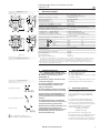
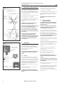
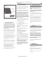
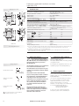
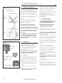
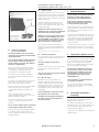
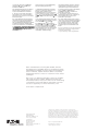
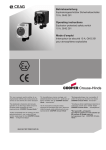
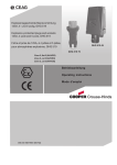
CROUSE-HINDS
Betriebsanleitung
Operating instructions
Mode d’emploi
SERIES
Explosionsgeschützte Installationsschalter
GHG 273
Explosion protected installation switches
GHG 273
Interrupteur d’ éclairage pour atmosphères explosives
GHG 273
GHG 270 7003 P0001 D/E/F (n)
Explosionsgeschützte
Installationsschalter
Typ GHG 273
Explosion protected
installation switches
type GHG 273
Interrupteurs d’éclairage
pour atmosphères explosives
type GHG 273
Inhalt:
Contents:
Contenu:
Inhalt........................................................ 2
Contents.................................................. 2
Contenu................................................... 2
Maßbild.................................................... 3
Dimensional drawings.............................. 6
Plans cotés............................................... 9
Anschlussbilder........................................ 3
Wiring diagrams....................................... 6
Schéma des connexions.......................... 9
1 Technische Angaben................................ 3
1
Technical Data.......................................... 6
1 Caractéristiques techniques.................... 9
2Sicherheitshinweise................................. 3
2 Safety instructions................................... 6
2 Consignes de sécurité............................. 9
3Normenkonformität.................................. 3
3 Conformity with standards....................... 6
3 Conformité avec les normes.................... 9
4Verwendungsbereich............................... 3
4 Field of application................................... 6
4 Domaine d’utilisation............................... 9
5 Verwendung / Eigenschaften................... 4
5 Use / Properties....................................... 7
5 Utilisation / Propriétés.............................10
6Installation................................................ 4
6Installation................................................ 7
6Installation...............................................10
6.1Montage................................................... 4
6.1Mounting.................................................. 7
6.1Montage..................................................10
6.2Öffnen des Gerätes /
Elektrischer Anschluss............................. 4
6.2 Opening the device /
Electrical connection................................ 7
6.2 Ouverture du dispositif /
Raccordement électrique........................10
6.3Kabel- und Leitungseinführungen;
Verschlussstopfen.................................... 5
6.3 Cable entries (KLE);
blanking plug............................................ 8
6.3 Entrées de câble (KLE);
bouchons de fermeture..........................11
6.4 Flansche und Metallplatten...................... 5
6.4 Flange and metal plates........................... 8
6.4 Plaques à brides......................................11
6.5 Schließen des Gerätes............................. 5
6.5 Closing the device / cover closure........... 8
6.5 Fermeture de l’appareil...........................11
6.6Inbetriebnahme........................................ 5
6.6 Taking into operation................................ 8
6.6 Mise en service.......................................11
7 Instandhaltung / Wartung......................... 5
8Reparatur / Instandsetzung /
Änderungen............................................. 5
8 Repairs / Overhaul /
Modification............................................. 8
8 Réparation /
Remise en état........................................11
9 Entsorgung / Wiederverwertung.............. 5
7 Maintenance / Servicing........................... 8
9 Disposal / Recycling................................. 8
7 Maintien / Entretien................................11
9 Évacuation des déchets / Recyclage.......11
Konformitätserklärung separat beigelegt.
2
Declaration of conformity, enclosed separately.
EATON’s Crouse-Hinds Business
Déclaration de conformité, jointe séparément.
Explosionsgeschützte Installationsschalter
Typ GHG 273
1
Maßbilder in mm
64
55
85
X75
85
115
X52
5,6
6,7
Technische Angaben
Gerätekennzeichnung nach 94/9/EG und Norm:
EG-Baumusterprüfbescheinigung:
Bemessungsspannung:
Bemessungsstrom:
Kurzschlussvorsicherung:
Schaltvermögen EN 60947-4-1 AC 5a:
Schaltvermögen EN 60947-4-2 AC 5b:
Zulässige Umgebungstemperatur:
(Abweichende Temperaturen sind bei Sonderversionen möglich)
53
20
64
55
85
X75
85
115
X52
5,6
6,7
35
20
GHG 273
Zul. Lagertemperatur in Originalverpackung:
Schutzart nach
EN/IEC 60529:
Schutzklasse nach EN/IEC 61140:
Leitungseinführung (Listenausführung):
geeignete Leitungen und Prüfdrehmomente
der Druckschraube
Dichtung 1+2 1 2
min.
max. (1)(2)
Dichtung 2
min.
1 2
max. (2)
Anschlussklemme:
PE - Anschlussklemme:
Prüfdrehmomente:
Einschraubgewinde der KLE M25:
Deckelschrauben:
Anschlussklemmen:
Gewicht (Listenausführung):
(1)
X = Befestigungsmaße
Anschlussbilder
Sicherheitshinweise
-20° C bis +40° C
IP 66 (Listenausführung)
I - wird von den Geräten erfüllt
1 x M25 oder 2 x M 25 (Ø 10 -15 mm)
2 x Bohrung M20
Ø
Nm
10,0
13,0
13,5
15,0
2 x 1,5 - 2,5 mm²
4 x 1,5 - 2,5 mm²
2,3
2,6
1,5
2,3
3,0 Nm
2,0 Nm
2,5 Nm
ca. 0,32 kg
Ausschalter 2-polig
L(N)
a
Die Installationsschalter sind nicht für Zone
0 und Zone 20 geeignet.
Es entspricht den aufgeführten Normen, in der
separat beigelegten Konformitätserklärung.
Sie sind bestimmungsgemäß in unbeschädigtem und einwandfreiem Zustand zu betreiben.
Vor Inbetriebnahme müssen die Installationsschalter entsprechend der im Abschnitt 6
genannten Anweisung geprüft werden.
L
Taster 1S+1Ö
L(N)
Normenkonformität
Das Betriebsmittel ist gemäß
DIN EN ISO 9001:2008 und
EN ISO/IEC 80079-34:2011 entwickelt, gefertigt
und geprüft worden.
Die Anforderungen der EN/IEC 60079-31, u.a.
in Bezug auf übermäßige Staubablagerungen und Temperatur, sind vom Anwender zu
beachten.
Wechselschalter 1S+1Ö
3
Zielgruppe dieser Anleitung sind
Elektrofachkräfte und unterwiesene
Personen in Anlehnung an die
EN/IEC 60079-14.
Die auf den Installationsschaltern angegebene Temperaturklasse und Explosionsgruppe ist zu beachten.
L
D II 2 G Ex de II C T6
D II 2 D Ex tD A21 IP66 T 80° C
PTB 98 ATEX 3121
bis 250 V; 50/60 Hz
max. 16 A
max. 20 A gL
230 V / 16 A
230 V / 16 A
-20° C bis +40° C (Listenausführung)
Die Prüfungen der Klemmbereiche und Prüfdrehmomente wurden mit Metalldornen durchgeführt. Bei der
Verwendung von Leitungen mit unterschiedlichen Fertigungstoleranzen und Materialeigenschaften kann der
Klemmbereich variieren. Bitte verwenden Sie im Zwischenbereich die Kombination aus Dichtung 1 + 2.
(2) Bei der Wahl der Dichtungsgummis darauf achten, dass bei zukünftigen Wartungsarbeiten an der KLE, die
Druckschraube nachgezogen werden kann.
2
L
D
Beachten Sie die nationalen Sicherheits- und
Unfallverhütungsvorschriften und die
nachfolgenden Sicherheitshinweise in dieser
Betriebsanleitung, die wie dieser Text in
Kursivschrift gefasst sind!
Die Schaltfunktion wird nur mit
aufgeschraubter Schalterwippe erreicht
EATON’s Crouse-Hinds Business
4
Verwendungsbereich
Die Installationsschalter sind zum Einsatz in
explosionsgefährdeten Bereichen der Zonen 1
und 2 sowie der Zonen 21 und 22 gemäß
EN/IEC 60079-10-1 und EN/IEC 60079-10-2
geeignet!
Die eingesetzten Gehäusematerialien einschließlich der außenliegenden Metallteile
bestehen aus hochwertigen Werkstoffen, die
einen anwendungsgerechten Korrosionsschutz
und Chemikalienresistenz in „normaler
Industrieatmosphäre“ gewährleisten:
– schlagfestes Polyamid
– Edelstahl AISI 316 L
Bei einem Einsatz in extrem aggressiver
Atmosphäre, können Sie zusätzliche Informationen über die Chemikalienbeständigkeit der
eingesetzten Kunststoffe bei Ihrer zuständigen
Cooper Crouse-Hinds Niederlassung erfragen.
3
Explosionsgeschützte Installationsschalter
Typ GHG 273
5
Bild 1
Gerätehalter Größe 1
Befestigungslöcher „B“
Verwendung / Eigenschaften
Die Installationsschalter dienen zur Ein- und
Ausschaltung von Lichtstromkreisen bis max.
16 A in explosionsgefährdeten Bereichen (siehe
technische Daten). Temperaturklasse, Explosionsgruppe, zulässige Umgebungstemperatur,
siehe technische Daten.
Die Installationsschalter sind auch im „normalen Industriebereich“ verwendbar.
für Wandund Gitterrinnenbefestigung
Die Schaltwippe ist mit einem selbstleuchtenden Schild gemäß § 7 der Arbeitsstättenverordnung versehen und frei von radioaktiven
Zusätzen.
Angaben aus Punkt 3 und 4 sind bei der
Verwendung zu berücksichtigen.
B
Andere als die beschriebenen Anwendungen
sind ohne schriftliche Erklärung der
Fa. Cooper Crouse-Hinds nicht zulässig.
Beim Betrieb sind die in der Betriebsanleitung unter Punkt 7 genannten Anweisungen
zu beachten.
Die Verantwortung hinsichtlich bestimmungsgemäßer Verwendung dieser
Installationsschalter unter Bezugnahme der
in der Anlage vorhandenen Rahmenbedingungen (s. Technische Daten) liegt allein
beim Betreiber.
für Rohrbefestigung
6
Bild 2
Gehäuseunterteil
- Einführung unten -
Schaltersockel
(nicht mit einem harten
Gegenstand
(z.B. Schraubendreher)
betätigen)
- PE-Anschluss unten
Gehäusedeckel
- Typenschild unten
Installation
Für das Errichten / Betreiben sind die relevanten
nationalen Vorschriften (z.B. Betriebssicherheitsverordnung, Gerätesicherheitsgesetz in
Deutschland) sowie die allgemein anerkannten
Regeln der Technik maßgebend
(EN/IEC 60079-14).
Wird der Installationsschalter mit den Leitungseinführungen nach unten montiert, ist der
Schaltereinsatz und der Gehäusedeckel um
180° zu drehen (siehe Bild 2).
Der Installationsschalter ist zur Befestigung auf
den CEAG-Gerätehaltern Größe 1 mittels
selbstschneidende Schrauben geeignet (siehe
Bild 1).
Die betreffende Montageanleitung ist zu
beachten.
6.2
Öffnen des Gerätes/
Elektrischer Anschluss
Der elektrische Anschluss des Betriebsmittels darf nur durch Fachpersonal erfolgen.
(EN/IEC 60079-14)
Vor Öffnen der Geräte ist die Spannungsfreiheit sicherzustellen bzw. sind geignete
Schutzmaßnahmen zu ergreifen.
Die ordnungsgemäß abisolierten Anschlussleitungen der Kabel sind unter Berücksichtigung
einschlägiger Vorschriften anzuschließen.
Die Isolation der Anschlussleitungen muss
bis an die Klemme heranreichen. Der Leiter
selbst darf nicht beschädigt sein.
Wird der Installationsschalter mit der Leitungseinführung nach unten montiert, ist Punkt 6.1
und Bild 2 zu beachten.
Nach der Demontage des Schaltersockels, zur
leichteren Einführung der Kabel und Leitungen,
muss der Sockel vor dem elektrischen
Anschluss wieder ordnungsgemäß montiert
werden.
Die minimal und maximal anschließbaren
Leiterquerschnitte sind zu beachten (siehe
technische Daten).
Unsachgemäße Installation und Betrieb der
Schalter kann zum Verlust der Garantie
führen.
Alle Schrauben und/oder Muttern der
Anschlussklemmen, auch die der nicht
benutzten, sind fest anzuziehen.
6.1
Bei übermäßigem Anziehen kann der
Anschluss beeinträchtigt oder beschädigt
werden.
Montage
Die Montage des Gerätes kann ohne Öffnen
des Gehäuses erfolgen. Die Installationsschalter dürfen bei der Direktmontage an der Wand
nur an den vorgesehenen Befestigungspunkten
eben aufliegen. Die gewählte Schraube muss
der Befestigungsöffnung angepasst sein (siehe
Maßbild) und sie darf die Öffnung nicht
beschädigen (z.B. Verwendung einer Unterlegscheibe).
Das Gerät ist mit mindestens 2 Schrauben
diagonal zu befestigen.
Bei übermäßigem Anziehen der Befestigungsschrauben kann das Gerät beschädigt
werden.
4
D
EATON’s Crouse-Hinds Business
Zur Aufrechterhaltung der Zündschutzart ist
der Leiteranschluss mit besonderer Sorgfalt
durchzuführen.
Die Anschlussklemmen sind für den Anschluss
von Kupferleitern ausgelegt.
Bei der Verwendung von mehr- oder feindrähtigen Anschlusskabeln und Anschlussleitungen
sind die Aderenden entsprechend den
geltenden nationalen und internationalen
Vorschriften zu behandeln (z.B. Verwendung von
Aderendhülsen).
Explosionsgeschützte Installationsschalter
Typ GHG 273
6.4
Bild 3
Gehäuseunterteil
PE Anschlussleitung
Flansche und Metallplatten*
Die für die Wartung / Instandhaltung von
elektrischen Betriebsmitteln in explosionsgefährdeten Bereichen geltenden Bestimmungen wie EN/IEC 60079-17 sind einzuhalten.
Der Metallflansch ist so zu montieren, dass die
IP-Schutzart gewährleistet bleibt. Dabei ist auf
die Unversehrtheit der Dichtung zu achten.
Vor Öffnen des Gehäuses Spannungsfreiheit
sicherstellen bzw. geeignete Schutzmaßnahmen ergreifen.
Achtung: Beim Anziehen der Hutmutter der
Metall – KLE (z.B. Typ ADE;) ist die Verschraubung mit einem geeigneten Werkzeug gegen
Verdrehen zu sichern.
Von außen herangeführte PE-Leitungen sind auf
die dafür vorgesehene PE-Klemme am Flansch
anzuschließen. Der maximale Anschlussquer-schnitt beträgt 6 mm².
* z.Zt. nicht bescheinigt für Kategorie II D
6.3
Kabel-und Leitungseinführungen
(KLE); Verschlussstopfen
6.5
Es dürfen generell nur bescheinigte KLEs
und Verschlussstopfen verwendet werden.
Für bewegliche Leitungen sind Trompetenverschraubungen oder andere geeignete
Einführungen mit zusätzlicher Zugentlastung zu verwenden.
Alle Fremdkörper sind aus dem Gerät zu
entfernen.
Die für die eingesetzten KLE maßgebenden
Montagerichtlinien sind zu beachten.
Um die Mindestschutzart herzustellen, sind
nicht benutzte Einführungsöffnungen mit einem
bescheinigten Verschlussstopfen zu verschließen. Es ist darauf zu achten, dass bei der
Installation der KLE die für den Leitungsdurchmesser geeigneten Dichtungseinsätze
verwendet werden.
Bei ausschneidbaren Dichtungseinsätzen ist
sicherzustellen, dass der Einsatz ordnungsgemäß dem Leitungsdurchmesser angepasst
wird.
Zur Sicherstellung der erforderlichen Mindestschutzart sind die KLE fest anzuziehen.
Zur Sicherstellung der erforderlichen
Mindestschutzart sind die Deckelschrauben
fest anzuziehen.
Bei übermäßigem Anziehen kann die
Schutzart beeinträchtigt werden.
6.6
Die erforderlichen Wartungsintervalle sind
anwendungsspezifisch und daher in Abhängigkeit von den Einsatzbedingungen vom Betreiber
festzulegen.
Im Rahmen der Wartung sind vor allem die Teile,
von denen die Zündschutzart abhängt, zu
prüfen (z.B. Unversehrtheit der druckfesten
Komponenten, des Gehäuses, der Dichtungen
und der Kabel- und Leitungseinführungen).
Sollte bei einer Wartung festgestellt werden,
dass Instandsetzungsarbeiten erforderlich sind,
ist Abschnitt 8 dieser Betriebsanleitung zu
beachten.
Schließen des Gerätes
Der Gehäusedeckel ist so aufzusetzen, dass
der Schutzkragen oben ist.
Beim Einsatz von KLE mit einer niedrigeren als
der für das Gerät zutreffenden IP-Schutzart,
(siehe Seite 3, technische Daten) wird die
IP-Schutzart des gesamten Gerätes reduziert.
Instandhaltung / Wartung
Müssen Metallflansche demontiert werden
(z.B. zum Bohren von Einführungsöffnungen),
ist bei der Montage zur Aufrechterhaltung der
Mindestschutzart auf den korrekten Sitz der
Flansche zu achten (siehe Bild 3).
Achtung: Metallflansche, Metallplatten und
Metallverschraubungen müssen in den
Potentialausgleich miteinbezogen werden.
Metallflansch für
Metalleinführungen
7
D
Inbetriebnahme
Vor Inbetriebnahme des Betriebsmittels sind
die in den einzelnen nationalen Bestimmungen
genannten Prüfungen durchzuführen. Außerdem ist vor der Inbetriebnahme die korrekte
Funktion und Installation des Betriebsmittels in
Übereinstimmung mit dieser Betriebsanleitung
und anderen anwendbaren Bestimmungen zu
überprüfen.
Die Stößel des Schaltersockels nicht zum
Testen mit einem harten Gegenstand
(z.B. Schraubendreher) betätigen.
Unsachgemäße Installation und Betrieb
der Installationsschalter kann zum Verlust
der Garantie führen.
8
Reparatur / Instandsetzung /
Änderungen
Instandsetzungsarbeiten / Reparaturen dürfen
nur Originalteile von CEAG / Cooper CrouseHinds (nachfolgend CCH) verwendet werden.
Bei Schäden an der druckfesten Kapselung
ist nur ein Austausch zulässig. Im Zweifelsfalle
ist das betroffene Betriebsmittel an CCH zur
Reparatur zurückzugeben.
Reparaturen, die den Explosionsschutz
betreffen, dürfen nur von CCH oder einer
qualifizierten Elektrofachkraft in Übereinstimmung mit national geltenden Regeln
durchgeführt werden (EN/IEC 60079-19).
Umbauten oder Änderungen am Betriebsmittel sind nicht gestattet.
Ausgenommen ist das Anbringen von zusätzlichen KLE im Rahmen der Zulassung des
Betriebsmittels.
9
Entsorgung /
Wiederverwertung
Bei der Entsorgung des Betriebsmittels sind die
jeweils geltenden nationalen Abfallbeseitigungsvorschriften zu beachten.
Bei übermäßigem Anziehen kann die
Schutzart beeinträchtigt werden.
Alle nicht benutzten metrischen CEAG KLE
sind mit dem bescheinigten CEAG-Verschluss
für metrische KLE zu verschließen.
Zur Erleichterung der Wiederverwertbarkeit von
Einzelteilen sind Kunststoffteile mit dem
Kennzeichen des verwendeten Kunststoffes
versehen.
Programmänderungen und -ergänzungen sind
vorbehalten.
EATON’s Crouse-Hinds Business
5
Explosions protected installation switches
type GHG 273
1
Dimensions in mm
64
55
85
X75
85
115
X52
5.6
6.7
Technical data
Marking acc. to 94/9/EC and directive:
EC type examination certificate:
Rated voltage:
Rated current:
Short circuit back-up fuse:
Switching capacity EN 60947-4-1 AC 5a:
Switching capacity EN 60947-4-2 AC 5b:
Perm. ambient temperature:
(Special versions permit deviating temperature ranges)
53
20
64
55
85
X75
85
115
X52
5.6
6.7
35
20
GHG 273
X = Fixing dimensions
Perm. storage temperature in original packing:
Protection category acc. to EN/IEC 60529:
Insulation class
acc. to EN/IEC 61140:
Cable entry (catalogue version):
suitable cables and test torques of the
pressure srew
seel 1+2 1 2
min.
max. (1)(2)
seel 2
min.
1 2
max. (2)
Supply terminal:
PE-terminal:
Test torques:
Test torque for screw in thread cable entry
Cover screws
Terminals
Weight (catalogue version):
Safety instructions
The operations must be carried
out by electrical suitably trained in
hazardous area with knowledge of
increased safety explosion protection
IEC/EN 60079-14.
Wiring diagrams
The installation switches are not suitable for
Zone 0 and Zone 20 hazardous areas.
On-Off switch 2-pole
Push button switch
1S+1Ö
L(N)
L
They shall be used for their intended
purpose and in perfect and clean condition.
Prior to taking the installation switches
into operation, they shall be checked in
accordance with the instruction as per
section 6.
L(N)
The switch function is only realized
with closed enclosure cover
6
The temperature class and explosion group
marked on the installation switches shall be
observed.
The requirements of the IEC/EN 60079-31
regarding excessive dust deposits and
temperature to be considered from the user.
L
-20° C up to +40° C
IP 66 ( catalogue version)
I - is complied with by the installation switches
1 x M25 or 2 x M25 (Ø 10 - 15 mm)
2 x drilling M20
Ø
Nm
10.0
13.0
13.5
15.0
2 x 1.5 - 2.5 mm²
4 x 1.5 - 2.5 mm²
2.3
2.6
1.5
2.3
3.0 Nm
2.0 Nm
2.5 Nm
approx. 0.32 kg
The tests of clamping ranges and torque values were performed with metal mandrel. The clamping range can
vary by using cables with different manufacturing tolerances and material properties. Please use the
combination of sealing 1 + 2 for the intermediate region.
(2) When selecting the seal rubber, ensure that the pressure screw can be tightened when carrying out any
future maintenance work on the cable entry.
a
Change over switch
1S+1Ö
D II 2 G Ex de II C T6
D II 2 D Ex tD A21 IP66 T 80° C
PTB 98 ATEX 3121
up to 250 V; 50/60 Hz
max. 16 A
max. 20 A gL
230 V / 16 A
230 V / 16 A
-20° C up to +40° C (catalogue version)
(1)
2
L
GB
Observe the national safety rules and
regulations for prevention of accidents as
well as the safety instructions included in
these operating instructions and set in
italics the same as this text!
EATON’s Crouse-Hinds Business
3
Conformity with standards
Das Betriebsmittel ist gemäß
DIN EN ISO 9001:2008 und
EN ISO/IEC 80079-34:2011 entwickelt, gefertigt
und geprüft worden.
Es entspricht den aufgeführten Normen, in der
separat beigelegten Konformitätserklärung.
4
Field of application
The installation switches are suitable for use in
Zones 1 and 2 as well as in Zones 21 and 22
hazardous areas acc. to IEC/EN 60079-10-1 and
IEC/EN 60079-10-2!
The enclosure materials employed, including
the exterior metal parts, are made of highquality materials which ensure a corrosion
protection and resistance to chemical
substances corresponding to the requirements
in a “normal industrial atmosphere”:
– impact resistant polyamide
– special steel AISI 316 L
In case of use in an extremely aggressive
atmosphere, please refer to manufacturer.
Explosions protected installation switches
type GHG 273
5
Fig. 1
Size 1 apparatus holder
Fastening holes “B”
Use / Properties
The installation switches are designed for
switching on and off light circuits in hazardous
areas up to 16 A (see technical data). The
temperature class, explosion group and
permissible ambient temperature, see technical
data.
The installation switches can also be used in
a ”normal industrial area“.
for walland channel
fixing
The switch rocker is provided with a luminescent label in acc. with § 7 of the Workshop
regulations and free from any radioactive
additives.
The data as per point 3 and 4 shall be taken
into account with the use.
B
Applications other than described are not
permitted without Cooper Crouse Hinds
prior written consent.
For the operation, the instructions stated in
section 7 of the operating instructions shall
be observed.
The user alone is responsible for the
appropriate use of this installation switch in
consideration of the basic conditions
existing at the plant (see technical data).
for pipe
fixing
6
Fig. 2
Enclosure base
- entry from
bottom side -
Installation
For the mounting and operation, the respective
national regulations (e. g. Betr.Si.V., equipment
safety law for Germany) as well as the general
rules of engineering shall be observed
(IEC/EN 60079-14).
The improper installation and operation
of switches may result in the invalidation
of the guarantee.
6.1
Mounting
The installation switches can be mounted
without opening their enclosure.
Switch basel
(Testing the switch socket
with a hard object (screwdriver)
is not permitted.)
- PE-terminal on the bottom
Enclosure cover
- type label on bottom
In case the switches are mounted directly onto
the wall, they may rest evenly only at the
respective fastening points. The chosen screw
shall match the fastening hole (see dimensional
drawing) and it must not damage the hole (e. g.
use of a washer). The device shall be fastened
diagonally with at least 2 screws.
GB
The installation switch is suitable for fixing onto
CEAG apparatus holders size 1 by means of
self-cutting screws (see fig. 1).
The respective mounting instructions shall
be observed.
6.2
Opening the device /
Electrical connection
The electrical connection of the device may
only be carried out by skilled staff
(IEC/EN 60079-14).
Before opening the apparatus, ensure that
it has been isolated from the voltage supply,
or take appropriate protective measures.
Taking into account the respective regulations,
the properly bared conductors of the cables
shall be connected.
The insulation of the conductors shall reach
up to the terminal. The conductor itself shall
not be damaged.
If the installation switch is mounted with the
cable entries on bottom, point 6.1 and fig. 2 will
have to be observed.
After dismantling the switch base in order to
facilitate the introduction of cables, such switch
base will have to be properly fitted in again prior
to the electrical connection.
The connectible min. and max. conductor
cross-sections will have to be observed (see
technical data).
All screws and/or nuts of the supply terminals,
also of those remaining vacant, shall be
tightened down.
Excessive tightening may affect or damage
the connection.
The conductors shall be connected with
special care in order to maintain the
explosion category.
The supply terminals are designed for the
connection of copper conductors.
If multi- or fine-wire connecting cables are
used, the wire ends will have to be handled in
acc. with the applicable national and international rules (e. g. use of ferrules).
If the screws are overtightened, the
apparatus can be damaged.
When the installation switch is mounted with
the cable entries on bottom side, the switch
insert and the enclosure cover must be turned
through 180° (see fig.2).
EATON’s Crouse-Hinds Business
7
Explosions protected installation switches
type GHG 273
6.4
Fig. 3
Enclosure base
PE-connection
Flange and metal plates*
The relevant national regulations which
apply to the maintenance/servicing of
electrical apparatus in explosive atmospheres, shall be observed
(e. g. IEC/EN 60079-17).
Flange plates shall be fitted so that the
IP protection in maintained. Pay attention to
the proper seat of the sealing.
Before opening the enclosure make sure
that the apparatus is disconnected from the
voltage, or take the appropriate protective
measures.
Attention: When tightening the cap nut of
the metal cable entry (e.g.type ADE;
CMDEL), the screwing is to be protected
against twisting by means of a suitable tool.
PE conductors fed from outside are to be
connected to the PE terminal provided on the
flange. The maximum cross-section is 6 mm²
category.
6.3
Cable entries (KLE);
blanking plugs
Generally, only certified cable entries and
blanking plugs are permitted for use.
Flexible cables shall be used with trumpetshaped cable glands or other suitable
entries with additional pull-relief.
* not yet certified for category II D
6.5
The enclosure cover shall be fitted so that the
protective collar is on the upper part.
Any foreign matter shall be removed from
the apparatus.
In order to ensure the required minimum
protection category, the cover screws are to
be tightened down.
The mounting directives applicable to the cable
entries used shall be observed.
Overtightening might impair the protection
category.
Unused holes shall be closed with a certified
blanking plug in order to establish the minimum
protection category. In case of sealing inserts
that are cut out, it shall be ensured that the
insert is properly adapted to the cable diameter.
6.6
In order to ensure the required minimum
protection category, the cable glands are to be
tightened down.
Overtightening might impair the protection.
All vacant metric CEAG cable entries shall be
closed with the certified CEAG blanking plug for
metric cable entries.
The required maintenance intervals depend on
the respective application and will therefore
have to be determined by the user dependent
on the conditions of use.
When servicing the apparatus, particularly
those parts that are decisive for the type of
protection against explosion, will have to be
checked (e. g. intactness of flameproof
enclosed components, enclosure, cable glands,
efficacy of the cover gaskets).
If during servicing repairs prove to be necessary, section 8 of these operating instructions
will have to be observed.
Closing the device /
cover closure
When using cable entries with a lower IP
protection than that which applies to the device
(see page 6, technical data), the IP protection of
the whole device will be reduced.
Care has to be taken that when fitting the cable
entries, sealing inserts appropriate to the cable
diameter are used.
Maintenance / Servicing
If flange plates have to be removed in case of
installation switches (e.g. for drilling entry
holes), attention shall be paid to the proper fit of
the flange plate when mounting them in order
to maintain the minimum protection category
(see fig. 3).
Attention: Metal flanges, metal plates and
metal cable glands shall be included in the
equipotential earth connection.
Metal flange for
metal cable glands
7
GB
Taking into operation
Prior to taking the apparatus into operation, the
tests specified in the relevant national
regulations will have to be carried out. Apart
from that, the correct functioning and installation of the apparatus in accordance with these
operating instructions and other applicable regulations will have to be checked.
Testing the switch socket with a hard object
(screwdriver) is not permitted.
Incorrect installation and use of the
installation switches can invalidate the
guarantee.
8
Repairs / Overhaul /
Modification
Repairs may only be carried out with genuine
CCH/CEAG spare parts.
In case of a damaged flameproof enclosure,
only its replacement is permitted. In case of
doubt, the respective apparatus will have to be
returned for repair to CCH/CEAG.
Repairs that affect the explosion protection,
may only be carried out by CCH/CEAG
or a qualified electrician in compliance
with the applicable national rules
(e. g. IEC/EN 60079-19).
Modifications to the apparatus or changes
of its design are not permitted.
Except for the mounting of additional cable
entries in accordance with the approval of the
apparatus.
9
Disposal / Recycling
When the apparatus is disposed of, the
respective national regulations on waste
disposal will have to be observed.
In order to facilitate the recycling of individual
components, plastic parts have been provided
with the identification mark of the plastic
material used.
Subject to modifications or supplement of the
product range.
8
EATON’s Crouse-Hinds Business
Interrupteurs d’éclairage pour
atmosphères explosives type GHG 273
1
Dimensions en mm
64
55
85
X75
85
115
X52
5,6
6,7
53
64
55
85
X75
85
115
X52
5,6
6,7
35
Caractéristiques techniques
Marquage selon 94/9/CE et directive:
Attestation d’examen CE de type:
Tension nominale:
Courant nominal:
Fusible maximal de court-circuit
adm. placé en amont:
Puissance de coupure EN 60947-4-1 AC 5a:
Puissance de coupure EN 60947-4-2 AC 5b:
Température ambiante admissible:
(Autres températures possibles avec des modèles spéciaux)
20
20
GHG 273
X = dimensions de fixation
F
Temp. de stockage dans l’emballage d’origine:
Indice de protection selon EN/CEI 60529:
Classe d’isolation selon EN/IEC 61140:
Entrée de câble (modèle de liste):
câbles appropriés et couples d’essai de la vis
de pression
phoque 1+2 1 2
min.
max. (1)(2)
phoque 2
min.
1 2
max. (2)
Bornes de connexion:
Borne du conducteur de protection:
Couples d’essai:
Couple d' essai pour l’entrée de câble
Vis du couvercle
Bornes
Poids à vide (modèle de liste):
D II 2 G Ex de II C T6
D II 2 D Ex tD A21 IP66 T 80° C
PTB 98 ATEX 3121
jusqu’à 250 V; 50/60 Hz
16 A maxi
20 A gL maxi
230 V / 16 A
230 V / 16 A
-20° C à +40° C(modéle de liste)
-20° C à +40° C
IP 66 (modéle de liste)
I - est remplie par les interrupteurs d’éclairage
1 x M25 / 2 x M25 (Ø 10 - 15 mm)
2 x persaçe M20
Ø
Nm
10,0
13,0
13,5
15,0
2 x 1,5 - 2,5 mm²
4 x 1,5 - 2,5 mm²
2,3
2,6
1,5
2,3
3,0 Nm
2,0 Nm
2,5 Nm
env. 0,32 kg
(1) Les tests des plages de serrage et les valeurs de couple de serrage ont été réalisés avec un mandrin
métallique. La plage de serrage peut varier légèrement selon le type de câble et les propriétés des matériaux
utilisés. Pour la zone intermédiaire, veuillez utiliser la combinaison des bagues d'étanchéité 1 + 2.
(2) Lors de la sélection des bagues d’étanchéité au moment de l’installation, il faut s’assurer qu’il reste une marge
de serrage suffisante au niveau du chapeau du presse étoupe. Cela permettra de pouvoir resserrer le presse
étoupe lors d’une future maintenance.
2
Consignes de sécurité
Les interrupteurs d’éclairage ne
conviennent pas à l’emploi dans la
zone 0, zone 20. Le groupe d’explosion et la classe de température indiqués sur
les appareils devront être respectés.
a
Schéma des connexions
Seuls des interrupteurs d’éclairage intacts
et sans défaut de fabrication devront être
employés pour la fonction qui leur est
dévolue.
Commutateur
disjoncteur à 2 pôles
L(N)
L
Commutateur inverseur
1 contact de travail +
1 contact de repos
Bouton-poussoir
1 contact de travail +
1 contact de repos
Avant la mise en service, les interrupteurs
d’éclairage doivent être vérifiées selon
l’instruction donnée dans la section 6.
L
L
Les exigences des CEI/EN 60079-31 en ce
qui concerne des dépôts de poussière
démesurés et une température doivent être
considérées par I’utilisateur.
Respectez les prescriptions nationales de
sécurité et de prévention contre les accidents
ainsi que les consignes de sécurité énumérées en italique dans ce mode d’emploi.
L(N)
3
Conformité avec les normes
Les Appareils ont été conçues, fabriquées et
contrôlées suivant DIN EN ISO 9001:2008 et
EN ISO/IEC 80079-34:2011.
Les Appareils sont conformes aux normes
reprises dans la déclaration de conformité.
4
Domaine d’utilisation
Les interrupteurs d’éclairage conviennent à
l’emploi en zones 1 et zones 2 ainsi que
l’emploi en zones 21 et zones 22 d’une
atmosphère explosive selon CEI/EN 60079-10-1
et CEI/EN 60079-10-2.
Pour l’enveloppe, y compris les pièces
métalliques extérieures, des matières de qualité
supérieure ont été employées. Elles assurent
une protection appropriée contre la corrosion et
une résistance contre des agents chimiques en
“atmosphère industrielle normale”:
– polyamide anti-choc
– acier spécial AISI 316 L.
En cas d‘utilisation en atmosphère extrèmement
corrosive, vous pouvez obtenir des informations
complémentaires sur la résistance chimique des
plastiques utilisés chez la succursale Cooper
Crouse-Hinds de votre région.
La fonction de commutateur est seulement réalisé avec enceinte fermée couvrir
EATON’s Crouse-Hinds Business
9
Interrupteurs d’éclairage pour
atmosphères explosives type GHG 273
5
Fig. 1
Porte-appareils taille 1
Trous de fixation ”B“
pour
fixation au
mur et à la
rainure de
grille
Utilisation / Propriétés
Les interrupteurs d’éclairage servent à
enclencher et déclencher des circuits d’éclairage jusqu’à 16 A maxi en atmosphère
explosive (voir les caractéristiques techniques).
Quant à la classe de température, le groupe
d’explosion et la température ambiante
admissible, voir les caractéristiques techniques.
Les interrupteurs d’éclairage peuvent aussi être
employées en ”atmosphère industrielle
normale“.
L’actionneur est pourvu d’une étiquette
luminescente qui, selon le §7 du règlement
pour des lieux d’utilisation, est libre des
substances radioactives.
B
Pour l’utilisation, les consignes des
sections 3 et 4 devront être respectées.
Des emplois autres que ceux décrits ne sont
admis qu’avec l’approbation écrite de CEAG.
Lors de l’exploitation, les instructions selon
point 7 de ce mode d’emploi doivent être
respectées.
pour
fixation au
tube
Seul l’utilisateur est responsable de l’emploi
conforme de interrupteur d’éclairage, en
tenant compte des conditions générales
exposées dans la notice (voir Caractéristiques techniques).
6
Fig. 2
Embase
- entrée par le bas -
Installation
Pour l’installation et l’exploitation de ces
appareils, la règlementation nationale en
vigueur (en Allemagne par ex. Betr.Si.V.,
réglementation de sécurité des appareils) ainsi
que les règles de la technique généralement
reconnues devront être respectées
(CEI/EN 60079-14).
L’installation ou l’utilisation incorrecte de
ces interrupteurs d’éclairage à bornes peut
entraîner la perte de la garantie.
Socle
d’interrupteur
(Test de la prise de l'interrupteur
avec un objet dur (tournevis) ne est
pas autorisée.)
- Connexion à la terre en bas
Couvercle
- Etiquette de repérage en bas
6.1
Montage
Le montage de l’appareil peut se faire sans
ouvrir l’enveloppe. En cas de montage direct
sur un mur, les interrupteurs d’éclairage ne
doivent reposer que sur les points de fixation
prévus.
La vis choisie doit être en rapport avec le trou
de fixation (voir plan coté) et elle ne doit pas
endommager le trou (par ex. emploi d’une
rondelle).
L’appareil doit être fixé en diagonale avec au
moins 2 vis.
Si les vis sont forcées, il est possible que
l’appareil soit endommagé.
10
EATON’s Crouse-Hinds Business
F
Si l’interrupteur d’éclairage est monté avec les
entrées de câble dirigées vers le bas, l’insert de
commutation et le couvercle de l’enveloppe
doivent être tournés de 180° (voir fig. 2).
L’interrupteur d’éclairage convient à un montage
sur les plaques de montage CEAG taille 1, avec
vis autotaraudeuses(voir fig. 1).
Les instructions pour le montage devront
être respectées.
6.2
Ouverture du dispositif /
Raccordement électrique
Le raccordement électrique du dispositif ne
doit être éffectué uniquement par une
personne qualifiée (CEI/EN 60079-14).
Avant ouverture de l’enveloppe, mettre
l’appareil hors-tension et prendre les
mesures préventives appropriées.
En tenant compte des règlements respectifs,
les conducteurs dûment dénudés des câbles
sont raccordés.
L’isolation doit couvrir le conducteur jusqu’à
la borne. Le conducteur lui-même ne doit
pas être endommagé.
Si l’interrupteur d’éclairage est monté de telle
manière que les entrées de câble se trouvent
en bas, il faudra respecter les prescriptions de
l’alinéa 6.1 et correspondre à la fig. 2.
Si des composants ont été retirés pour faciliter
l’introduction des câbles, ceux-ci devront être
remis dûment en place avant le raccordement
électrique.
Les sections minimales et maximales
admissibles des conducteurs doivent être
respectées (voir caractéristiques techniques).
Toutes les vis et/ou écrous des bornes de
connexion, ainsi que celles des bornes non
utilisées, doivent être serrées à fond.
Un serrage excessif des vis peut endom-mager l’appareil.
Afin de maintenir le mode de protection, la
connexion des conducteurs doit se faire très
soigneusement.
Les bornes sont prévues pour le raccordement
de conducteurs en cuivre.
En cas d’utilisation des câbles de connexion
multifilaires ou à fils de faible diamètre, les
extrémités des conducteurs doivent être traités
selon la règlementation nationale et internationale en vigueur (par ex. emploi des embouts).
Interrupteurs d’éclairage pour
atmosphères explosives type GHG 273
6.4
Fig. 3
Embase
Connexion
à la terre
Plaques à brides*
Si les plaques à brides doivent être démontées
(pour percage d’entrées de câble, par exemple)
il faudra veiller lors du montage au maintien de
l’indice de protection en replacant correctement
la plaque (voir fig. 3).
Les plaques à brides sont montées de telle
façon à ce que l’indice de protection IP soit
respecté. Il faut également veiller au bon état
du joint d’étanchéité.
Attention: les brides et plaques de fond
métalliques et les presse-étoupe métalliques
doivent être reliés au même potentiel.
brides métalliques
pour entrée de
câble métallique
6.3
Entrées de câble (KLE) /
Bouchons de fermeture
De manière générale, seuls des bouchons
obstruateurs et des entrées de câble certifiés
doivent être utilisés.
Pour des câbles flexibles il faudra utiliser des
presse-étoupes en forme de trompette ou
d’autres entrées appropriées avec décharge
de traction supplémentaire.
Lorsque des entrées de câble avec un indice
de protection IP inférieur à celui du dispositif
ont employées (voir page 9), l’indice de
protection IP de l’ensemble sera réduit.
Les directives pour le montage applicables
aux entrées de câble montées doivent être
respectées.
Les entrées non utilisées doivent être fermées
avec un bouchon obstruateur certifié pour
établir l’indice de protection minimum.
Lors du montage des entrées de câble il faudra
veiller à ce que des joints d’étanchéité
correspondant au diamètre du câble soient
utilisées.
Si des joints devaient être découpés sur
mesure, il faudra veiller à ce que ceux-ci soient
adaptés au diamètre du câble.
Les entrées de câble doivent être serrées à
fond pour conserver l’indice de protection
minimum.
7
F
Maintien/Entretien
La règlementation nationale en vigueur
pour le maintien et l’entretien du matériel
électrique pour atmosphère explosive
devra être respectée (CEI/EN 60079-17).
Avant d’ouvrir l’enveloppe, débrancher
le dispositif de la tension ou prendre des
mesures préventives appropriées.
Les intervalles de service requis dépendent de
l’emploi spécifique et devront donc être fixés
par l’utilisateur en tenant compte des conditions d’exploitation.
Attention: Lors du serrage de l'écrou borgne
de l'entrée de câble métallique (par ex. du
type ADE; CMDEL), il faut veiller à ce que le
presse-étoupe ne se torde. Pour ce faire, le
mieux est d'utiliser un outil approprié.
Lors de l’entretien des appareils et surtout des
composants qui sont essentiels à la protection
contre l’explosion, devront être vérifiés (par ex.
intégrité des composants antidéflagrants, de
l’enveloppe, des joints d’étanchéité et des
entrées de câble).
Des conducteurs PE amenés de l’extérieur
doivent être connectés à la borne PE prévue à
cet effet sur la bride. La section maximale est
de 6 mm².
Si, lors d’une inspection technique, on constate
que des travaux d’entretien sont nécessaires,
il faudra suivre le point 8 de ce mode d’emploi.
* pour le moment, pas encore certifié Catégorie II D
6.5
Fermeture de l’appareil
Le couvercle doit être posé de telle manière sur
l’enveloppe que le collet protecteur se trouve
en haut.
Tout corps étranger doit être ôté de
l’appareil.
Les vis de couvercle doivent être serrées à fond
afin de maintenir l’indice de protection
minimum.
Si les vis sont forcées, cela peut être nuisible
à l’indice de protection.
6.6
Mise en service
Avant la mise en service du matériel, les
vérifications spécifiées dans les règlements
nationaux individuels devront être exécutées.
De plus, il faudra vérifier son fonctionnement
et installation corrects en conformité avec ce
mode d’emploi et avec d’autres règlements
y applicables.
Test de l’interrupteur socket avec un objet
dur (tournevis) n’est pas autorisée.
L’installation et l’exploitation inadéquates
des fiches et prises peuvent entraîner la
perte de la garantie.
8
Réparations / Remise en état
Des réparations ne doivent être exécutées qu’à
l’aide des pièces de rechange d’origine CEAG.
En cas de défauts sur l’enveloppe antidéflagrante, seul un remplacement sera admis.
Dans le doute, l’appareil défectueux devra être
retourné à CEAG pour être réparé.
Des réparations relatives à la protection
contre l’explosion même, ne devront être
exécutées que par CEAG ou par un électricien qualifié et en conformité avec la
règlementation nationale en vigueur
(CEI/EN 60079-19).
Toute modification ou transformation de
ces appareils est interdite.
Seul le montage d'entrées de câble supplémentaires en conformité avec l’homologation
des appareils est accepté.
9
Évacuation des déchets /
Recyclage
Lors de l’évacuation de ce matériel électrique,
la règlementation nationale respective en
vigueur devra être respectée.
Pour faciliter la réutilisation des composants
individuels, des pièces en matière plastique ont
été repérées de la marque distinctive de la
matière plastique employée.
Au cas où elles seraient forcées, cela pourrait
porter préjudice à l’indice de protection.
Toutes les entrées de câble métriques CEAG
non utilisées doivent être fermées avec un
bouchon obsturateur certifié pour des entrées
de câble métriques.
Sous réserve de modification ou d’informations
supplémentaires.
EATON’s Crouse-Hinds Business
11
CZ: "Tento návod k použití si m žete vyžádat
ve svém mate ském jazyce u p íslušného
zastoupení spole nosti Cooper CrouseHinds/CEAG ve vaší zemi."
H: "A kezelési útmutatót az adott ország
nyelvén a Cooper Crouse-Hinds/CEAG cég
helyi képviseletén igényelheti meg."
P: "Se for necessária a tradução destas
instruções de operação para outro idioma da
União Europeia, pode solicita-la junto do seu
representante Cooper Crouse-Hinds/CEAG"
DK: "Montagevejledningen kan oversættes til
andre EU-sprog og rekvireres hos Deres
Cooper Crouse-Hinds/CEAG leverandør"
I: "Se desiderate la traduzione del manuale
operativo in un´altra lingua della Comunit à
Europea potete richiederla al vostro
rappresentante Cooper Crouse-Hinds/CEAG"
PL: Niniejsz instrukcj obs ugi w odpowiedniej
wersji j zykowej mo na zamówi w
przedstawicielstwie firmy Cooper-CrouseHinds/CEAG na dany kraj.
LT: Šios naudojimo instrukcijos, išverstos J su
gimt j kalb , galite pareikalauti atsakingoje
"Cooper Crouse-Hinds/CEAG" atstovyb je savo
šalyje.
S: "En översättning av denna montage- och
skötselinstruktion till annat EU - språk kan vid
behov beställas från Er Cooper CrouseHinds/CEAG- representant"
LV: "Šo ekspluat cijas instrukciju valsts valod
varat piepras t j su valsts atbild gaj Cooper
Crouse-Hinds/CEAG p rst vniec b ."
SK: "Tento návod na obsluhu Vám vo Vašom
rodnom jazyku poskytne zastúpenie spolo nosti
Cooper Crouse-Hinds/CEAG vo Vašej krajine."
M: Jistg u jitolbu dan il-manwal fil-lingwa
nazzjonali tag hom ming and ir-rappre entant
ta' Cooper Crouse Hinds/CEAG f'pajji hom.
SLO: "Navodila za uporabo v Vašem jeziku
lahko zahtevate pri pristojnem zastopništvu
podjetja Cooper Crouse-Hinds/CEAG v Vaši
državi."
E: "En caso necesario podrá solicitar de su
representante Cooper Crouse-Hinds/CEAG
estas instrucciones de servicio en otro idioma
de la Union Europea"
EST: "Seda kasutusjuhendit oma riigikeeles
võite küsida oma riigis asuvast asjaomasest
Cooper Crouse-Hindsi/CEAG esindusest."
FIN: "Tarvittaessa tämän käyttöohjeen käännös
on saatavissa toisella EU:n kielellä Teidän
Cooper Crouse-Hinds/CEAG - edustajaltanne"
GR:
Cooper CrouseHinds/CEAG"
NL: "Indien noodzakelijk kan de vertaling van
deze gebruiksinstructie in een andere EU-taal
worden opgevraagd bij Uw Cooper CrouseHinds/CEAG - vertegenwoordiging"
RUS: "При необходимости, вы можете запрашивать
перевод данного руководства на другом языке
ЕС или на русском от вашего
Cooper Crouse-Хиндс / CEAG - представителей."
Eaton is dedicated to ensuring that reliable, efficient
and safe power is available when it’s needed most. With
unparalleled knowledge of electrical power management
across industries, experts at Eaton deliver customized,
integrated solutions to solve our customers’ most critical
challenges.
Our focus is on delivering the right solution for the application. But, decision makers demand more than just
innovative products. They turn to Eaton for an unwavering
commitment to personal support that makes customer
success a top priority. For more information, visit
www.eaton.com/electrical.
Cooper Crouse-Hinds GmbH
Neuer Weg-Nord 49
69412 Eberbach
E-Mail: [email protected]
www.crouse-hinds.de
© 2015 Eaton
All Rights Reserved
Printed in Germany
Publication No.
GHG 270 7003 P0001 D/E/F (n)
Auflage/11.15/CS
dd
Changes to the products, to the information contained in this
document, and to prices are reserved; so are errors and omissions.
Only order confirmations and technical documentation by Eaton is
binding. Photos and pictures also do not warrant a specific layout or
functionality. Their use in whatever form is subject to prior approval
by Eaton. The same applies to Trademarks (especially Eaton, Moeller,
and Cutler-Hammer). The Terms and Conditions of Eaton apply, as
referenced on Eaton Internet pages and Eaton order confirmations.
Eaton is a registered trademark.
All trademarks are property
of their respective owners.