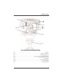
1
Vision blue Pan and Tilt Head
V4092-0001
Operators Guide
V4092-4980/1
7JTJPOCMVF
1BO5JMU)FBE
Vision blue pan and tilt head
Publication Part No.V4092-4980
Issue 1
August 2010
Published by
Vitec Group Videocom Division
Technical Publications Department
William Vinten Building
Western Way
Bury St Edmunds
Suffolk IP33 3TB
UK
Email: [email protected]
Copyright © Vitec Group plc 2010
All rights reserved throughout the world. No part of this
document may be stored in a retrieval system, transmitted,
copied or reproduced in any way, including, but not limited to,
photocopy, photograph, magnetic or other record without the
prior agreement and permission in writing of Vitec Group plc.
Trademark Acknowledgements
Vinten® and Vision® are registered trademarks of
Vitec Group plc.
Disclaimer
Camera Dynamics Limited reserves the right, without notice, to
revise this documentation and make changes in content from
time to time without obligation to provide notification of such
revision or change. Revised documentation may be obtainable
from Vinten or downloadable from the website
(www.vinten.com). Camera Dynamics Limited reserves the
right, without notice, to make changes in equipment design or
performance as progress in engineering, manufacturing or
technology may warrant.
2
Operators guide
4BGFUZSFBEUIJTGJSTU
6OEFSTUBOEJOHUIFTFJOTUSVDUJPOT
English
The original instructions presented
in this operators guide were written
in English, and subsequently
translated into other languages. If
you are unable to understand these
instructions, contact Vinten or your
distributor to obtain a translation of
the original instructions (EU
Countries).
Eesti
ǼȜȜȘȞȚțȐ
ȅȚ ĮȡȤȚțȑȢ ȠįȘȖȓİȢ ĮȣIJȠȪ IJȠȣ
ȠįȘȖȠȪ ȖȚĮ IJȠ ȤİȚȡȚıIJȒ
ıȣȞIJȐȤșȘțĮȞ ıIJĮ ǹȖȖȜȚțȐ țĮȚ
ȝİIJĮijȡȐıIJȘțĮȞ ıIJȘ ıȣȞȑȤİȚĮ ıİ
ȐȜȜİȢ ȖȜȫııİȢ. ǼȐȞ įȣıțȠȜİȪİıIJİ
ȞĮ țĮIJĮȜȐȕİIJİ ĮȣIJȑȢ IJȚȢ ȠįȘȖȓİȢ,
İʌȚțȠȚȞȦȞȒıIJİ ȝİ IJȘ Vinten Ȓ IJȠ
įȚĮȞȠȝȑĮ ıĮȢ ȖȚĮ ȞĮ ȜȐȕİIJİ ȝȚĮ
ȝİIJȐijȡĮıȘ IJȦȞ ĮȡȤȚțȫȞ ȠįȘȖȚȫȞ
(ȋȫȡİȢ ǼǼ).
ȻɔɅȽȺɊɋɄɂ
Ɉɪɢɝɢɧɚɥɧɢɬɟ ɢɧɫɬɪɭɤɰɢɢ,
ɩɪɟɞɫɬɚɜɟɧɢ ɜ ɧɚɫɬɨɹɳɨɬɨ
ɪɴɤɨɜɨɞɫɬɜɨ ɧɚ ɩɪɨɢɡɜɨɞɢɬɟɥɹ,
ɛɹɯɚ ɧɚɩɢɫɚɧɢ ɧɚ ɚɧɝɥɢɣɫɤɢ ɟɡɢɤ,
ɚ ɫɥɟɞ ɬɨɜɚ - ɩɪɟɜɟɞɟɧɢ ɧɚ ɞɪɭɝɢ
ɟɡɢɰɢ. Ⱥɤɨ ɧɟ ɪɚɡɛɢɪɚɬɟ ɬɟɡɢ
ɟɡɢɰɢ, ɫɜɴɪɠɟɬɟ ɫɟ ɫ Vinten ɢɥɢ ɫ
ȼɚɲɢɹ ɞɢɫɬɪɢɛɭɬɨɪ, ɡɚ ɞɚ
ɩɨɥɭɱɢɬɟ ɨɪɢɝɢɧɚɥɧɢɬɟ
ɢɧɫɬɪɭɤɰɢɢ (ɡɚ ɫɬɪɚɧɢɬɟ ɨɬ
ȿɜɪɨɩɟɣɫɤɢɹ ɫɴɸɡ).
ýesky
Danish
Deutsch
Español
Pokyny uvedené v této operátorské
pĜíruþce byly pĤvodnČ napsány
anglicky a následnČ byly pĜelo_eny
do ostatních jazykĤ. Nerozumíte-li
tČmto pokynĤm, kontaktujte
spoleþnost Vinten nebo svého
distributora, abyste získali pĜeklad
originálních pokynĤ (þlenské státy
EU).
Français
De originale instruktioner, der
præsenteres i denne
betjeningsvejledning, er skrevet på
engelsk og derefter oversat til
andre sprog. Hvis du ikke forstår
disse instruktioner bedes du
kontakte Vinten eller vor forhandler
for at få en oversættelse af de
originale instruktioner (EU-lande).
Gaeilge
Die Originalanleitung in diesem
Bedienungshandbuch wurde auf
Englisch verfasst und anschließend
in andere Sprachen übersetzt. Bei
Verständnisproblemen in einer der
übersetzten Sprachen kontaktieren
Sie bitte Vinten oder Ihren
Fachhändler; dort erhalten Sie eine
Übersetzung der ursprünglichen
Anleitung (EU-Staaten).
Käesoleva kasutajajuhendi algtekst
on koostatud inglise keeles ning
seejärel tõlgitud teistesse
keeltesse. Kui juhend osutub teie
jaoks arusaamatuks, võtke juhendi
emakeelse tõlke hankimiseks
ühendust Vinteni või kohaliku
esindajaga (Euroopa Liidu riigid).
Italiano
Las instrucciones originales que se
indican en esta guía del operador
se han redactado en inglés y
posteriormente se han traducido a
otros idiomas. Si no entiende estas
instrucciones, póngase en contacto
con Vinten o con su distribuidor
para obtener una traducción de las
instrucciones originales (para
países de la UE).
Les instructions originales
présentées dans ce guide
d'utilisation ont été écrites en
anglais puis traduites dans d'autres
langues. Si vous ne comprenez pas
ces instructions, contactez Vinten
ou votre revendeur pour obtenir
une traduction des instructions
originales (pour les pays de l'UE).
Scríobhadh na treoracha bunaidh
don treoirleabhar oibritheora seo as
Béarla, agus aistríodh iad go
teangacha eile ina dhiaidh sin.
Mura bhfuil tú in ann na treoracha
seo a thuiscint, téigh i dteagmháil le
Vinten nó le do dháileoir, chun
aistriúchán de na treoracha
bunaidh a fháil (Tíortha an AE).
Le istruzioni originali presentate in
questa guida per l'operatore sono
in lingua inglese e
successivamente tradotte nelle
altre lingue. Qualora le istruzioni
non fossero disponibili nella lingua
desiderata, potete contattare
Vinten o il vostro distributore per
ricevere la traduzione delle
istruzioni originali (Paesi UE).
3
Vision blue pan and tilt head
Latviešu
Português
ŠajƗ operatora rokasgrƗmatƗ
iekƺautie norƗdƯjumi sƗkotnƝji tika
sarakstƯti angƺu valodƗ un pƝc tam
pƗrtulkoti citƗs valodƗs. Ja
nesaprotat šos norƗdƯjumus
svešvalodƗ, sazinieties ar Vinten
vai tirgotƗju, lai saƼemtu
norƗdƯjumu tulkojumu (kƗdƗ no ES
dalƯbvalstu valodƗm).
Română
Lietuviǐ
InstrucĠiunile originale prezentate
în acest ghid pentru operatori au
fost scrise în limba engleză, úi
traduse ulterior în alte limbi. În
cazul în care nu înĠelegeĠi aceste
instrucĠiuni, contactaĠi Vinten sau
distribuitorul dumneavoastră pentru
a obĠine o traducere a
instrucĠiunilor originale (ğările UE).
Šiame operatoriaus vadove
pristatomos pirminơs instrukcijos
parašytos anglǐ kalba ir vơliau
išverstos Ƴ kitas kalbas. Jei šiǐ
instrukcijǐ nesuprantate,
susisiekite su „Vinten“ arba savo
platintoju ir gaukite pirminiǐ
instrukcijǐ vertimą (ES šalies
kalba).
Magyar
Slovensky
A kezeloi útmutatóban található
utasítások angol nyelven íródtak,
és utólag fordították azokat más
nyelvekre. Ha nem érti ezen
utasításokat, kérjük, vegye fel a
kapcsolatot a Vintennel vagy a
helyi képviselettel, és igényelje az
eredeti utasítások fordítását (EU
országok).
L-istruzzjonijiet originali
ippreĪentati f'din il-gwida ta'
operaturi kienu miktuba bl-IngliĪ, u
sussegwentement maqluba fllingwi ohra. Jekk ma tistax tifhem
dawn l-istruzzjonijiet, ikkuntattja lil
Vinten jew id-distributur tieghek
biex tikseb traduzzjoni ta' listruzzjonijiet originali (PajjiĪi ta'
UE).
Originalno besedilo teh navodil za
uporabo je bilo napisano v
anglešþini in prevedeno v ostale
jezike. ýe ne razumete teh navodil,
se obrnite na podjetje Vinten ali
lokalnega zastopnika, ki vam bo
posredoval originalna navodila
(velja za dr_ave EU).
Suomi
Nederlands
De oorspronkelijke instructies in
deze bedieningshandleiding zijn
geschreven in het Engels en
vervolgens in andere talen
vertaald. Als het onmogelijk is deze
instructies te begrijpen, neemt u
contact op met Vinten of met uw
distributeur om een vertaling te
bemachtigen van de
oorspronkelijke instructies (EGlanden).
Polski
Oryginalne instrukcje
zamieszczone w niniejszym
podrĊczniku operatora zostały
napisane w jĊzyku angielskim, a
nastĊpnie przetłumaczone na inne
jĊzyki. JeĞli nie rozumieją PaĔstwo
tych instrukcji, prosimy
skontaktowaü siĊ z siedzibą lub
dystrybutorem Vinten, aby uzyskaü
tłumaczenie oryginalnych instrukcji
(kraje UE).
Pôvodné pokyny, uvedené v tomto
návode na obsluhu, boli napísané v
anglictine a následne preložené do
iných jazykov. Ak nerozumiete
týmto pokynom, obrátte sa na
spolocnost Vinten alebo vášho
distribútora, aby vám zaslal preklad
originálnych pokynov (krajiny EÚ).
Slovenšþina
Malti
4
As instruções originais
apresentadas no guia do operador
foram escritas em Inglês e
traduzidas para outros idiomas. Se
não conseguir compreender estas
instruções contacte a Vinten ou o
seu distribuidor para obter a
tradução das instruções originais
(Países da UE).
Svenska
Tähän käyttäjän oppaaseen
sisältyvät ohjeet on kirjoitettu alun
perin englanniksi ja käännetty
sitten muille kielille. Ellet ymmärrä
näitä ohjeita, ota yhteyttä Vinteniin
tai jälleenmyyjään ja pyydä
alkuperäisten ohjeiden käännöstä
(EU-maat).
Instruktionerna i denna handbok
skrevs ursprungligen på engelska
och har sedan översatts till flera
språk. Om du inte förstår dessa
instruktioner, kontakta Vinten eller
din återförsäljare för en ny
översättning av
originalinstruktionerna (EU-länder).
Operators guide
8BSOJOHTZNCPMTJOUIJT
0QFSBUPST(VJEF
Where there is a risk of personal
injury or injury to others, comments
appear highlighted by the word
WARNING!—supported by the
warning triangle symbol.
Where there is a risk of damage to the
product, associated equipment, process or
surroundings, comments appear highlighted
by the word CAUTION!
%JTQPTBMPGXBTUFCBUUFSJFT
Any batteries included with this product must
not be treated as household waste. By
ensuring these batteries are disposed of
correctly, you will help prevent potentially
negative consequences for the environment
and human health, and help conserve natural
resources. Please view the section on how to
remove the batteries from the product safely.
Hand the batteries over to the applicable
collection point for recycling waste batteries.
6TBHF
The Vision blue pan and tilt head is designed
for use by professional camera operators to
support and balance high performance
lightweight cameras and ancillary equipment
weighing up to 5 kg (11.1 lb.).
The Vision blue pan and tilt head must be
mounted onto a suitable tripod designed to
support the head, camera and accessories.
Warning!
1. Do NOT attempt to use
this product if you do not
understand how to operate
it.
2. Do NOT use this product
for any other purpose than
that specified in this Usage
statement.
3. Maintenance beyond that
detailed in this Operators
Guide must be performed
only by competent
personnel.
5
Vision blue pan and tilt head
5FDIOJDBMTQFDJGJDBUJPO
Weight, including pan bar, camera plate & bowl clamp . . . . . . . . . . . . . . . . . . . . . 2.4 kg (5.3 lb)
Height to mounting face . . . . . . . . . . . . . . . . . . . . . . . . . . . . . . . . . . . . . . . . . . 12.1 cm (4.76 in.)
Length . . . . . . . . . . . . . . . . . . . . . . . . . . . . . . . . . . . . . . . . . . . . . . . . . . . . . . . 12.9 cm (5.08 in.)
Width . . . . . . . . . . . . . . . . . . . . . . . . . . . . . . . . . . . . . . . . . . . . . . . . . . . . . . . . 14.8 cm (5.83 in.)
Capacity range @ 55 mm C of G - See balance chart (Fig. 3). . . . . . . . . 2.1–5.0 kg (4.6–11 lb)
Tilt range. . . . . . . . . . . . . . . . . . . . . . . . . . . . . . . . . . . . . . . . . . . . . . . . . . . . . . . . . . . . . . . . ±90°
Pan range . . . . . . . . . . . . . . . . . . . . . . . . . . . . . . . . . . . . . . . . . . . . . . . . . . . . . . . . . . . . . . 360°
Tripod fixing . . . . . . . . . . . . . . . . . . . . . . . . . . . . . . . . . . . . . . . . . . . . . . . . . . . . . . . . 75 mm ball
6
Operators guide
$POUFOUT
Safety - read this first. . . . . . . . . . . . . . . . . . . . . . . . . . . . . . . . . . . . . . . . . . . . . . 3
Technical specification . . . . . . . . . . . . . . . . . . . . . . . . . . . . . . . . . . . . . . . . . . . . 6
Contents . . . . . . . . . . . . . . . . . . . . . . . . . . . . . . . . . . . . . . . . . . . . . . . . . . . . . . . . 7
Components . . . . . . . . . . . . . . . . . . . . . . . . . . . . . . . . . . . . . . . . . . . . . . . . . . . . . 8
Introduction and description. . . . . . . . . . . . . . . . . . . . . . . . . . . . . . . . . . . . . . . 10
Balance . . . . . . . . . . . . . . . . . . . . . . . . . . . . . . . . . . . . . . . . . . . . . . . . . . . . . . . . . . . . . 10
Illuminated level bubble . . . . . . . . . . . . . . . . . . . . . . . . . . . . . . . . . . . . . . . . . . . . . . . . . 11
Pan and Tilt drag . . . . . . . . . . . . . . . . . . . . . . . . . . . . . . . . . . . . . . . . . . . . . . . . . . . . . . 11
Pan and Tilt brakes . . . . . . . . . . . . . . . . . . . . . . . . . . . . . . . . . . . . . . . . . . . . . . . . . . . . 11
Pan bar . . . . . . . . . . . . . . . . . . . . . . . . . . . . . . . . . . . . . . . . . . . . . . . . . . . . . . . . . . . . . 11
Camera mounting . . . . . . . . . . . . . . . . . . . . . . . . . . . . . . . . . . . . . . . . . . . . . . . . . . . . . 11
Operation . . . . . . . . . . . . . . . . . . . . . . . . . . . . . . . . . . . . . . . . . . . . . . . . . . . . . . 12
Fitting the pan bar . . . . . . . . . . . . . . . . . . . . . . . . . . . . . . . . . . . . . . . . . . . . . . . . . . . . . 12
Installing the head on a tripod . . . . . . . . . . . . . . . . . . . . . . . . . . . . . . . . . . . . . . . . . . . . 12
Mounting the camera . . . . . . . . . . . . . . . . . . . . . . . . . . . . . . . . . . . . . . . . . . . . . . . . . . . 12
Balancing the head . . . . . . . . . . . . . . . . . . . . . . . . . . . . . . . . . . . . . . . . . . . . . . . . . . . . 13
Operating the pan and tilt brakes . . . . . . . . . . . . . . . . . . . . . . . . . . . . . . . . . . . . . . . . . . 14
Operating the pan and tilt drag . . . . . . . . . . . . . . . . . . . . . . . . . . . . . . . . . . . . . . . . . . . 15
Maintenance . . . . . . . . . . . . . . . . . . . . . . . . . . . . . . . . . . . . . . . . . . . . . . . . . . . . 16
General . . . . . . . . . . . . . . . . . . . . . . . . . . . . . . . . . . . . . . . . . . . . . . . . . . . . . . . . . . . . 17
Cleaning. . . . . . . . . . . . . . . . . . . . . . . . . . . . . . . . . . . . . . . . . . . . . . . . . . . . . . . . . . . . . 16
Routine maintenance . . . . . . . . . . . . . . . . . . . . . . . . . . . . . . . . . . . . . . . . . . . . . . . . . . . 16
Battery replacement. . . . . . . . . . . . . . . . . . . . . . . . . . . . . . . . . . . . . . . . . . . . . . . . . . . . 16
Brake knob and drag control knob adjustment . . . . . . . . . . . . . . . . . . . . . . . . . . . . . . . 17
Parts list . . . . . . . . . . . . . . . . . . . . . . . . . . . . . . . . . . . . . . . . . . . . . . . . . . . . . . . 18
7
Vision blue pan and tilt head
$PNQPOFOUT
(8)
(7)
(1)
(2)
(6)
(3)
(5)
(4)
'JH7JTJPOCMVFQBOBOEUJMUIFBEGSPOUBOEMFGUIBOETJEF
'JH7JTJPOCMVFQBOBOEUJMUIFBEGSPOUBOEMFGUIBOETJEF
(1) . . . . . . . . . . . . . . . . . . . . . . . . . . . . . . . . . . . . . . . . . . . . . . . . 1/4 in. screw and pin assembly
(2) . . . . . . . . . . . . . . . . . . . . . . . . . . . . . . . . . . . . . . . . . . . . . . . . . . . . . . . . . . . . . . . . Slide plate
(3) . . . . . . . . . . . . . . . . . . . . . . . . . . . . . . . . . . . . . . . . . . . . . . . . . . . . . . . . . . . . . Tilt brake lever
(4) . . . . . . . . . . . . . . . . . . . . . . . . . . . . . . . . . . . . . . . . . . . . . . . . . . . . . . . . . . . . Pan brake lever
(5) . . . . . . . . . . . . . . . . . . . . . . . . . . . . . . . . . . . . . . . . . . . . . . . . . . . . . Tilt drag adjustment knob
(6) . . . . . . . . . . . . . . . . . . . . . . . . . . . . . . . . . . . . . . . . . . . . . . . . . . . . . . . . . . . Slide plate clamp
(7) . . . . . . . . . . . . . . . . . . . . . . . . . . . . . . . . . . . . . . . . . . . . . . . . . . . . . . . . . . . . . Pan bar clamp
(8) . . . . . . . . . . . . . . . . . . . . . . . . . . . . . . . . . . . . . . . . . . . . . . . . . . . . . . . . . . . . . . . . . . .Pan bar
8
Operators guide
(17)
(9)
(10)
(11)
(16)
(12)
(15)
(13)
(14)
'JH7JTJPOCMVFQBOBOEUJMUIFBEMFGUIBOETJEF
'JH7JTJPOCMVFQBOBOEUJMUIFBEMFGUIBOETJEF
(9) . . . . . . . . . . . . . . . . . . . . . . . . . . . . . . . . . . . . . . . . . . . . . . . . . . . . . . . . . . . . . . . . . . Platform
(10) . . . . . . . . . . . . . . . . . . . . . . . . . . . . . . . . . . . . . . . . . . . . . . . . . . . . . . . Battery compartment
(11) . . . . . . . . . . . . . . . . . . . . . . . . . . . . . . . . . . . . . . . . . . . . . . . . . . . . . . . Perfect Balance knob
(12) . . . . . . . . . . . . . . . . . . . . . . . . . . . . . . . . . . . . . . . . Push button for illuminated level bubble
(13) . . . . . . . . . . . . . . . . . . . . . . . . . . . . . . . . . . . . . . . . . . . . . . . . . . . Pan drag adjustment knob
(14) . . . . . . . . . . . . . . . . . . . . . . . . . . . . . . . . . . . . . . . . . . . . . . . . . . . . . . . . . . . . . . .Bowl clamp
(15) . . . . . . . . . . . . . . . . . . . . . . . . . . . . . . . . . . . . . . . . . . . . . . . . . . . . . Illuminated level bubble
(16) . . . . . . . . . . . . . . . . . . . . . . . . . . . . . . . . . . . . . . . . . . . . . . . . . . . . . . . . . . . . Pan bar mount
(17) . . . . . . . . . . . . . . . . . . . . . . . . . . . . . . . . . . . . . . . . . . . . . . . . . . . . . . . . . . Slide lock release
9
Vision blue pan and tilt head
*OUSPEVDUJPOBOEEFTDSJQUJPO
The Vision blue pan and tilt head has been designed to support and perfectly balance a range
of professional digital video cameras. The head embodies an adjustable spring counter
balancing mechanism, LF drag assemblies for pan and tilt motions and an adjustable camera
mounting plate with 1/4 in. screw and pin assembly. The placement of the pan and tilt brakes,
drag controls and counterbalance allows the operator to easily adjust the settings whilst
operating the camera.
#BMBODF
The balance system is easily adjusted using the Perfect Balance knob (10) located on the rear
of the head. The head supports payloads weighing between 2.1 to 5.0 Kg (4.6–11 lb). Maximum
and minimum payloads that can be balanced and tilt ranges are dependent on the weight of the
camera, accessories and on the Centre of Gravity (C of G) height. The counterbalance chart
(Fig. 3) shows the range of load and C of G height that can be maintained in balance. The
shaded area of the chart corresponds to those load/C of G combinations that can be balanced
over the full tilt range. The areas to the right indicate the progressively reducing tilt range with
greater load and higher C of G. Where a load/C of G combination falls outside of the chart it will
be necessary to increase or decrease the weight or the C of G height—if possible—to enable
the head to balance the load.
100
C of G Height above platform (mm)
±90
75
±60
±40
50
25
0
0
2
4
6
Payload mass (kg)
'JH$PVOUFSCBMBODFDIBSU
'JH$PVOUFSCBMBODFDIBSU
10
8
10
Operators guide
*MMVNJOBUFEMFWFMCVCCMF
Levelling the head is achieved using the level bubble (15) that can be illuminated when setting
up at locations with low lighting levels. In situations of low light, the level bubble can be
illuminated by pressing the push button (12). The bubble will be illuminated for 15 seconds. The
battery for the illuminated bubble is contained within a battery compartment (10) located under
the platform.
1BOBOE5JMUESBH
Both pan and tilt mechanisms incorporate the patented Vinten lubricated friction (LF) system to
ensure smooth movement of the camera about these axes. The pan and tilt drag is adjusted
using the pan drag adjustment knob (13) and tilt drag adjustment knob (5). The whip-pan facility
is unaffected by the pan drag setting.
1BOBOE5JMUCSBLFT
Both pan and tilt brakes allow each axis on the head to be locked at any chosen position. The
pan brake lever (4) and tilt brake lever (3) are located on the left-hand side of the head.
1BOCBS
Pan bar mounting points (16) are located at the rear of the head on either side of the camera
mounting platform. The pan bar (8) is attached using a pan bar clamp (7), with angular
adjustment available on the mount serrations. A fixed pan bar is supplied with an option to fit
another pan bar if required.
$BNFSBNPVOUJOH
The camera is attached to the head using a slide plate (2) that is attached to the camera and
then loaded from the rear of the platform (9) and secured in position by the slide plate clamp (6).
The clamp prevents inadvertent removal of the camera from the head. The slide plate (2) is
supplied with a 1/4 in. screw and pin assembly (1) to suit most lightweight digital video cameras.
11
Vision blue pan and tilt head
0QFSBUJPO
Fitting the pan bar
A single pan bar is supplied and is fitted to either the right or left-hand side of the head onto the
pan bar mounting (16).
To fit the pan bar:
Position the pan bar (8) onto the pan bar mounting (16).
Rotate the pan bar clamp (7) in a clockwise direction until the pan bar is secured.
A second pan bar can be fitted to the other side of the head if required.
*OTUBMMJOHUIFIFBEPOBUSJQPE
The Vision blue pan and tilt head is supplied with an integral 75 mm ball mount, designed for
installation on a compatible Vinten Vision tripod. Adaptors are available which enable the head
to be installed on tripods fitted with other mountings.
To install the head onto the tripod:
Remove the bowl clamp assembly (14) from the head by turning the assembly in a
counter-clockwise direction.
Position the head on the tripod, carefully lowering the head into the tripod bowl.
Using the pan bar to steady the head, refit the bowl clamp assembly (14) from below the
tripod bowl, turning the bowl clamp assembly (14) in an clockwise direction until the
head is held in position.
Apply the pan brake (4) and tilt brake (3) by turning the levers in a clockwise direction.
CAUTION!
DO NOT use force on the brake levers. Hand tighten only.
Level the head using the level bubble (15) and once level, tighten the bowl clamp
assembly (14) to secure the head in position. When attempting to level the head in
situations where there is low light, the level bubble can be illuminated by pressing the
push button (12) located on the rear of the head beneath the Perfect Balance knob (11).
The light will extinguish after approximately 15 seconds.
.PVOUJOHUIFDBNFSB
The head is supplied with a camera slide plate (2) fitted with a 1/4 in. pin assembly (1),
comprising a locating pin on a plate and a 1/4 in. camera mounting screw.
To mount the camera onto the head:
Remove the slide plate (2) from the head. Release the slide plate clamp (6) and press
the slide lock release (17), then slide the plate out to the rear of the platform (9).
12
Operators guide
Attach the slide plate (2) to the camera or camera mounting plate under the approximate
centre of the camera’s weight using the 1/4 in. screw and pin assembly (1).
Set the platform (9) level and apply both the pan and tilt brakes (4, 3).
CAUTION!
DO NOT use force on the pan and tilt brake levers. Hand tighten only.
Lower the camera onto the rear of the platform (9) and slide the plate into the track in
the platform (9), ensuring the slide lock release (17) snaps into position.
Using the pan bar (8) to steady the camera, tighten the slide plate clamp (6) in a
clockwise direction to secure the camera in position.
#BMBODJOHUIFIFBE
A perfectly balanced head allows operators to control camera movement with the minimal
amount of effort. Once balanced, the head and its payload can be set to any tilt position and
remain at that position, allowing operators to work hands-free.
The counterbalance chart (Fig. 3) illustrates the relationship between load and camera Centre
of Gravity (C of G) height for the head. The chart can be used to ascertain the suitability of the
head for any given combination of camera, lens and accessories. The shaded area of chart
corresponds to those load/C of G combinations that can be balanced over the full tilt range. The
areas to the right indicate the progressively reducing tilt range with greater load and higher C of
G. Where a load/C of G combination falls outside of the chart it will be necessary to increase or
decrease the weight or the C of G height to enable the head to balance the load.
Before balancing the head, ensure that the camera and lens, pan bar and all ancillary equipment
has been fitted. The head must be balanced whenever the camera and/or lens is changed, or
when ancillary equipment is added or removed.
Warning!
1. Do NOT exceed the maximum capacity of either the head or the tripod. The
system will become unstable and may fail.
2. Always support the camera payload when adjusting the Perfect Balance
knob (10) to prevent it falling away suddenly.
3. Keep hands clear of the moving platform to avoid trapping fingers.
To check camera balance:
Warning!
Steady the camera payload using the pan bar. Be prepared to prevent the
head falling away suddenly.
Reduce tilt drag to a minimum level by turning by turning the tilt adjustment drag knob
(5) counter-clockwise. Reduce the counterbalance to a minimum level by turning the
Perfect Balance knob (11) in clockwise direction.
Hold the pan bar (8) to steady the camera payload. Release the tilt brake (3).
13
Vision blue pan and tilt head
Tilt the head backwards and forwards to determine if the camera position is equally
balanced in both directions. The camera and payload must be positioned over the centre
of gravity.
If the camera’s C of G is not positioned over the head’s C of G, set the platform level and
apply the tilt brake (3). Position the camera correctly on the head by releasing the slide
plate clamp (6) and then sliding the camera on the camera slide plate (2), backwards or
forwards until it balances horizontally. Tighten the slide plate clamp (6) to secure the
camera in position. Re-check and adjust as necessary.
Warning!
Securely apply the slide plate clamp (6) when the camera is positioned, to
prevent the camera payload slipping.
Using the pan bar (8), tilt the head backwards and forwards. Turn the Perfect Balance
knob (11) clockwise until the camera remains in position and does not fall away when
the head is tilted and then released (hands-free).
Repeat the setup until perfect balance is achieved, when the camera remains set at any
angle from +90° to –90° without falling away or spri nging back.
NOTE: Maximum tilt angle is less than 90° for heavy p ayloads with a high C of G - refer
to the counterbalance chart (Fig. 3).
Apply the tilt brake (3) when balance is achieved to prevent the camera from moving
accidentally when not in use.
0QFSBUJOHUIFQBOBOEUJMUCSBLFT
Friction brakes on each axis allow the head to be locked at any chosen position. The operating
levers for the pan brake (4) and tilt brake (3) are fitted at the left-hand side of the head.
CAUTION!
DO NOT use the brakes to supplement drag, the head may be damaged.
When the brakes are not in use, always ensure they are fully released.
To apply the brake:
Turn the brake lever fully clockwise.
CAUTION!
DO NOT use force on the brake levers. Hand tighten only.
To release the brake:
Turn the brake lever fully counter-clockwise
14
Operators guide
0QFSBUJOHUIFQBOBOEUJMUESBH
Both the pan and tilt mechanisms incorporate the Vinten LF system to ensure smooth movement
of the camera about these axes. The tilt drag adjustment knob (5) is located on the right-hand
side of the head and the pan drag adjustment knob (13) is located at the back of the head,
beneath the platform (9).
NOTE: The whip-pan facility is not affected by the pan drag setting.
CAUTION!
Reduce drag to a minimum when the head is out of use for long periods,
to minimize wear on drag components.
Both drag adjustment knobs are provided with graduated scales. To increase drag, turn the knob
towards a higher graduation. To decrease drag, turn the knob towards a lower graduation.
15
Vision blue pan and tilt head
.BJOUFOBODF
(FOFSBM
Vinten products are robustly made to high engineering standards and little attention is required
to maintain serviceability save regular cleaning. Attention to the following points will ensure a
long and useful service life with minimum need for repair.
$MFBOJOH
During indoor use, the only cleaning required should be a regular wipe over with a lint-free cloth.
Dirt accumulated during storage may be removed using a semi-stiff brush. Particular attention
should be paid to the ball mounting face of the head, the space between the tilting assembly and
the base and the mounting bowl of the tripod.
Use out-of-doors under adverse conditions will require special attention. Salt spray should be
washed off with fresh water at the earliest opportunity. Sand and dirt acts as an abrasive and
should be removed using a semi-stiff brush or vacuum cleaner.
CAUTION!
DO NOT use solvent or oil-based cleaners, abrasives or wire brushes to
remove accumulations of dirt, as these damage the protective surfaces.
Use only detergent-based cleaners.
3PVUJOFNBJOUFOBODF
During use, check the following:
Check the illumination of the level bubble. Replace battery if necessary.
Check the effectiveness of the pan and tilt drag controls. Reset as necessary.
Check the effectiveness of the pan and tilt brakes. Reset as necessary.
No further routine maintenance is required.
#BUUFSZSFQMBDFNFOU
The battery illuminates the level bubble (14) when the push button (11) is pressed. The battery
should be replaced yearly or whenever the illumination is considered inadequate.
Warning!
If a payload is not fitted to the head, turn the Perfect Balance knob (10) fully
counter-clockwise to reduce the balancing force before tilting the head
forwards.
To replace the battery:
Tilt the head forwards to allow access to the battery compartment (10) and apply the tilt
brake (3).
Using a thin-bladed screwdriver or similar tool, prise off the battery cover (10.1).
16
Operators guide
Pull the battery (10.2) out of the battery compartment (10).
Push the replacement battery into the battery compartment, observing the correct
polarity.
CAUTION!
Use plastic tweezers when handling the battery. Avoid shortening the
battery by holding it by the circumference edge.
Refit the battery cover (10.1).
CAUTION!
DO NOT use force on the battery compartment. Ensure that the
compartment is correctly aligned with the fittings inside the head.
Press the push button (12) and ensure that the level bubble (15) is lit for approximately
15 seconds.
(10.1)
(10.2)
(10)
(3)
(11)
(15)
(12)
'JH3FQMBDJOHUIFCBUUFSZ
'JH3FQMBDJOHUIFCBUUFSZ
#SBLFLOPCBOEESBHDPOUSPMLOPCBEKVTUNFOU
The pan and tilt brakes (3, 4) and drag adjustment knobs (5, 13) may require adjustment after
prolonged use. These adjustments should be carried out by competent persons only. Contact
Vinten or your local Vinten distributor for servicing of the Vision blue pan and tilt head.
17
Vision blue pan and tilt head
1BSUTMJTU
The following lists include main assemblies, user-replaceable spare parts and optional
accessories. For further information regarding repair or spare parts, please contact Vinten or
your local distributor. For information online, visit our website at www.vinten.com.
.BJOBTTFNCMJFT
Vision blue pan and tilt head . . . . . . . . . . . . . . . . . . . . . . . . . . . . . . . . . . . . . . . . . . V4092-0001
Bowl clamp knob assembly . . . . . . . . . . . . . . . . . . . . . . . . . . . . . . . . . . . . . . . . . . . . . . 3330-30
Pan bar and clamp . . . . . . . . . . . . . . . . . . . . . . . . . . . . . . . . . . . . . . . . . . . . . . . . . . . . 3219-110
6TFSSFQMBDFBCMFTQBSFQBSUT
Brake knob spares kit . . . . . . . . . . . . . . . . . . . . . . . . . . . . . . . . . . . . . . . . . . . . . . . . 3431-900SP
1/4 in. pin adaptor. . . . . . . . . . . . . . . . . . . . . . . . . . . . . . . . . . . . . . . . . . . . . . . . . . . V4045-1006
Camera mounting slide plate spares kit, containing: . . . . . . . . . . . . . . . . . . . . . . . . V4043-1901
1 off Camera slide plate
2 off 3/8 in. camera screws
1 off 1/4 in. screw and pin assembly
0QUJPOBMBDDFTTPSJFT
Pozi Loc two stage tripod . . . . . . . . . . . . . . . . . . . . . . . . . . . . . . . . . . . . . . . . . . . . . . . . . 3819-3
Spreader. . . . . . . . . . . . . . . . . . . . . . . . . . . . . . . . . . . . . . . . . . . . . . . . . . . . . . . . . . . . . . 3363-3
Mid-level spreader . . . . . . . . . . . . . . . . . . . . . . . . . . . . . . . . . . . . . . . . . . . . . . . . . . V4032-0001
Set of three feet (for use with mid-level spreaders) . . . . . . . . . . . . . . . . . . . . . . . . . 3378-902SP
Tripod carrying strap. . . . . . . . . . . . . . . . . . . . . . . . . . . . . . . . . . . . . . . . . . . . . . . . . . . . 3425-3P
75 mm ball to 100 mm bowl adaptor . . . . . . . . . . . . . . . . . . . . . . . . . . . . . . . . . . . . . . U005-159
Soft case . . . . . . . . . . . . . . . . . . . . . . . . . . . . . . . . . . . . . . . . . . . . . . . . . . . . . . . . . . . . . 3358-3
18
Vision blue Pan and Tilt Head
V4092-0001
CHINA
The Vitec Group plc China
Rm 706, Tower B
Derun Building
YongAn Dongli A No. 8
Jianwai Ave, Chaoyang District
Beijing, China 100022
Tel.
+86 10 8528 8748
Fax.
+86 10 8528 8749
FRANCE
Vitec Group Videocom Division
171 Avenue des Grésillons
92635 GENNEVILLIERS Cedex
France
Tel.
+33 820 821 336
Fax.
+33 825 826 181
GERMANY
Vitec Group Videocom Division
Gebäude 16
Planiger Straße 34
55543 Bad Kreuznach
Germany
Tel.
+49 671/483 43 30
Fax.
+49 671/483 43 50
Vitec Group Videocom Division
Erfurter Straße 16
85386 Eching
Germany
Tel.
+49 89/321 58 200
Fax.
+49 89/321 58 227
JAPAN
Vinten Japan KK
P.A. Bldg. 5F
3-12-6 Aobadai
Meguro-ku Tokyo 153-0042
Japan
Tel.
+81 3 5456 4155
Fax.
+81 3 5456 4156
SINGAPORE
Vitec Group Videocom Division
6 New Industrial Road
#02-02 Hoe Huat Industrial Building
Singapore 536199
+65 6297 5776
Tel.
+65 6297 5778
Fax.
UK
Vitec Group Videocom Division
William Vinten Building
Western Way
Bury St Edmunds
Suffolk IP33 3TB
+44 1284 752 121
Tel.
Fax.
+44 1284 750 560
Sales Fax.
+44 1284 757 929
USA
Vitec Group Videocom Division
709 Executive Blvd
Valley Cottage
NY 10989
USA
+1 845 268 0100
Tel.
+1 845 268 0113
Fax.
Toll Free Sales:
+1 888 2 Vinten-
for more information, visit
www.vinten.com
Operators Guide
V4092-4980/1
Vinten ®
A Vitec Group brand