1
On Interface Objects In Object-Oriented Databases
Norman W Paton, Ghassan al-Qaimari and Khoa Doan
Department of Computing and Electrical Engineering,
Heriot-Watt University
Riccarton, Edinburgh EH14 4AS, Scotland, UK
e-mail: < norm,ghassan,vibama>@cee.hw.ac.uk
phone: +44-31-449-5111 ; fax: +44-31-451-3431
Abstract. This paper describes an approach to the support of interface objects in an object-oriented database, and outlines some of the consequences of
representing interface data as database objects. Existing architectures for implementing database interfaces are reviewed, and certain shortcomings identied,
which essentially stem from an impedance mismatch between the database and
its interface. It is shown how an existing graphical component set can be cleanly
and transparently integrated with an existing object-oriented database, thereby
removing the above impedance mismatch and providing persistent graphical data.
This interface can then be used to implement generic, tailorable and applicationspecic interface concepts, each of which is exemplied in the paper. a
a In: Proc. 12th British National Conference on Databases (BNCOD), D.S. Bowers
(ed), Springer-Verlag, LNCS 826, 153-169, 1994.
1 Introduction
It has been recognised for some time that interfaces to databases lag behind certain other areas of
database technology in terms of their maturity [1]. To remedy this situation it will be necessary for
progress to be made in two distinct but complementary areas:
The development of visual languages and systems which enhance the usability of database systems for all activities associated with an installation { querying, schema design, data modication, schema evolution, application development, data entry and database administration.
The development of eective tools for the implementation of database interfaces, which as well
as easing the implementation of the types of system mentioned above, facilitate the development
of application-specic interfaces and the tailoring of system-supported tools.
Most recent research into database interfaces focuses upon the rst of these areas, but the absence of
eective, fully integrated tools for the development of database interfaces has limited the number of
systems developed which embrace the full range of interface requirements associated with database
systems.
This paper is concerned principally with the second of the areas identied above, namely the production of tools for database interface development. The particular focus of this paper is on using
the database to implement its own interface { the close integration of tools for interface development
with the database system is consistent with the long-term trend in database systems towards more of
the functionality of an application being supported within the database system itself. For example,
deductive databases integrate an inference mechanism with a relational data store, and persistent
programming languages integrate imperative programming constructs with database storage managers. In each of these cases, the fully integrated approach is seen to be superior to the coupling of
pre-existing components, as no impedance mismatch is introduced.
1
When interfaces to databases are developed, it is common for a new form of impedance mismatch to
be introduced. The interface to the database is written using a user interface management system
(UIMS) or graphical component set, in a program which subsequently calls out to the database system
in order to access and store data. This leads to the following problems:
1. Graphical data manipulated by the interface cannot be stored directly in the database. This
means that graphical information, such as a schema diagram which has been laid out by the
user, must be mapped by the programmer onto the structures of the underlying data model. It
also means that visualisations of database objects cannot be stored readily in the database for
subsequent retrieval and display by the interface.
2. Development or modication of an interface to the database, or the implementation of an
application-specic interface, requires knowledge of the two independently developed systems
and the way in which they are linked.
3. Tools developed for the querying and manipulation of the database cannot be used on interface
data, and vice-versa.
This paper describes an approach to the provision of a fully integrated database interface development
system. The technique adopted is to integrate a graphical component set with an object-oriented
database (OODB) in such a way that the original component set is completely transparent to users.
This task has been eased by the facility to store both programs and data in the database, and by the
presence of object-oriented mechanisms, such as inheritance and encapsulation.
The paper is organised as follows. Related work is summarised in section 2, to present a context for
our architecture which is described in section 3. In section 4 it is shown how this fully integrated
approach can be exploited to support uniform access to graphical data, application-specic interfaces,
extensibility to support visualisations of advanced modelling constructs, and a multi-paradigm query
interface. Section 5 presents some conclusions.
2 Related Work
This section reviews dierent approaches to the implementation of graphical interfaces to databases.
No attempt is made to review the facilities which are provided by dierent interfaces, as that is not
the focus of this paper.
It is standard for graphical interfaces to be constructed using general-purpose interface development
systems, such as X-Windows toolkits or proprietary window managers [22, 7]. Such systems can then
communicate with the database in the same way as other application programs, using an embedded
query language, a procedure library, or inter-process communication.
It has long been recognised that object-oriented techniques are highly suitable for the implementation
of graphical component sets [25]. However, in the case of OODBs, it is common for the database
interface to be implemented using a system other than the database [25], even where the database is
associated with a powerful programming language [5].
An alternative strategy is to use a UIMS to control dialog and to support direct manipulation of
visual representations of database data [17]. In this approach, the high-level facilities of the UIMS
do facilitate some modication of an interface without requiring detailed knowledge of two programming systems. However, there is no direct support for persistent interface data, and changes to the
overall functionality of the interface rather than simply to the display component are likely to require
signicant programming eort.
More fully integrated techniques have, however, been proposed. In [18] a graphics programming
environment for PS-algol is described. In this approach, a small number of primitive graphics types
are built upon to yield a persistent graphics toolkit. A descendent of the original PS-algol system
for Napier88, which provides a complete windowing environment, is described in [8]. There are two
2
major dierences between these systems and the one described in this paper: in these approaches the
toolkit is implemented from a low level using the database language, and the database languages used
do not support an object-oriented model of data.
More similar approaches to that presented in this paper are described by [24, 6], in which the on-screen
representation of database objects is described using other database objects. However, these papers
do not describe how the object-oriented model is associated with the underlying display manager or
how interface extensibility can be achieved using overriding.
A combined approach, in which a UIMS is implemented using an object-oriented database, is described
in [16]. This approach enables the interactive specication of interfaces, and overcomes the impedance
mismatch associated with the use of a separate UIMS. The work described in this paper has a similar
motivation to [16], but the focus of this paper is at a lower level. Rather than describing how a UIMS
integrated with a database can be used, we present how a persistent graphical component set can
be constructed, and show how the resulting architecture can be easily extended using object-oriented
techniques. A more comprehensive description of integrated interface architectures is presented in
[21].
3 Architecture
3.1 Options
This section describes the architecture of a system which integrates an existing graphical component
set with the OODB ADAM [15]. The approach described here has been implemented in ADAM within
the ECLiPSe [14] persistent Prolog system, which includes the PCE graphical component set. The
approach is generally applicable, in that similar results could be obtained using dierent OODBs and
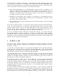
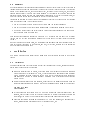
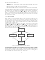
graphical component sets. The ADAM graphical toolkit is known as EDEN, and the relationships
between the major components of the interface are shown in Figure 1. EVE is a data browser and
manipulation tool, and is described further in section 4.2.
The premise which led to the development of EDEN is that it would be useful to be able to implement
ADAM graphical interfaces using ADAM itself. Two distinct architectures for such a system have
since been used:
1. Implement a graphical component set in ADAM which provides an object-oriented view of a
low-level window library.
2. Integrate ADAM with an existing graphical component set, in such a way that the component
set selected is hidden from ADAM programmers.
An implementation was attempted using the rst approach [26], which was built upon the Xlib library
of X-Windows. However, this approach was subsequently abandoned as the resulting system proved
to be prohibitively slow, and because substantial amounts of code were required to provide a toolkit
at an appropriately high level. Performance problems in this case stemmed from the large amount
of functionality which had to be supported using the (relatively slow) database language. When
using the toolkit approach, a greater proportion of the interface functionality is handled outside the
database, using routines written in C, although the nature of the back-end toolkit is hidden from the
EDEN programmer.
As signicant eort has been put into the provision of toolkits which support graphical objects such
as windows, dialog boxes, sliders, menus and pictures, any technique which enables such a component
set to be smoothly integrated with an OODB removes the need to start working at a lower level, and
enables re-use of existing interface toolkit facilities.
A characteristic of existing toolkits is that they have an object-oriented style, even when they are
programmed using conventional imperative languages, such as C. The approach taken in EDEN is to
provide a `view' of an existing toolkit using the constructs of the ADAM data model. Thus EDEN
3
EVE
EDEN
PCE
Component
Set
ADAM OODB
ECLiPSe
Persistent Prolog
DB
Figure 1: Components of system
programs are standard ADAM programs { database objects are created, related to each other, updated
and destroyed using standard ADAM operations. However, the sending of messages to objects which
are part of EDEN can have the side-eect of placing the object on screen, changing its representation
on screen, or removing it from the screen.
3.2 Menu Example
EDEN consists of a number of ADAM classes (50 at present), each of which represents an interface
construct { a menu, a button, a picture, a slider, etc. The way in which each of these concepts
is created and manipulated is very similar, which means that an integration of an OODB with a
component set can be achieved in a modest period of time. This section describes the approach using
the example of a menu.
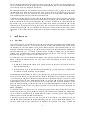
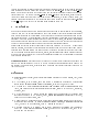
Figure 2: Sample EDEN menu.
A menu is a list of items displayed vertically on a screen, each of which can be selected using a pointing
device, such as a mouse. For example, gure 2 depicts a simple EDEN menu:
Where such a menu is considered as an object, it is seen to have certain properties which can be
4
specied as attributes on the class menu, including a name (File Options) and a number of members
(display, clear, ...). It is also necessary to associate some behaviour with a menu, so that the system
knows what to do when an item on the menu is selected. Furthermore, there is some functionality
associated with a menu { it can be opened, closed, and even destroyed. This is achieved by dening
a class menu as follows (the following examples do not use ADAM notation, but are intended to be
as self explanatory as possible { for a more detailed description of the actual ADAM code, see [3]):
class menu is_a window {
attributes {
name: string;
members: set of string;
}
methods {
make_component() {...}
...
}
}
In the above, it is assumed that the superclass of menu is window, which supports methods such as
open and close. A menu object is created in the same way as any other database object:
m = menu();
m.put_name("File Options");
m.put_members({"display","clear",...});
...
The crucial architectural feature of the interface is that there is no interaction at all with the graphical
toolkit during the creation of the menu object m. It is only when the menu is opened that it
becomes necessary to call the graphical toolkit. Sending the message open to the object m leads to
the invocation of the method make component attached to the class menu.
class window {
...
open() {
x_object_id = self.x_object_name();
if not (x_in_use(x_object_id)) {
self.make_component();
x_open(x_object_id);
}
}
}
It is the role of the make component method, which is dened on every EDEN class, to construct
the object in the toolkit which is equivalent to the EDEN object on which it is invoked. For the class
menu the denition of make component is as follows:
class menu is_a window {
...
make_component() {
x_menu_id = self.x_object_name();
if not (x_in_use(x_menu_id)) {
x_make_menu(x_menu_id,name);
for each m in members do
x_add_menu_item(x_menu_id,m);
5
super.make_component()
}
}
...
}
In the above denition, x menu id is the name of the menu in the toolkit which corresponds to the
EDEN menu object on which make component has been invoked. The algorithm rst checks to see if
the object x menu id already exists in the current invocation of the toolkit. If so, the routine exists. If
not, then calls are made to the toolkit which create the corresponding menu (x make menu), and then
add each of the members of the EDEN object to the toolkit object. Subsequently make component is
invoked on super, which leads to the invocation of the denition of make component on the superclass
of menu, namely window. This operation is responsible for handling features common to the creation
of all windows, such as size and cursor shape. The relationship between the EDEN and toolkit objects
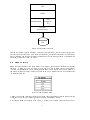
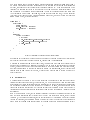
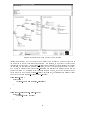
is depicted graphically in gure 3.
name
EDEN Menu
File Options
members
{display,clear,help,close}
Displayed-As
(PCE Object created when menu displayed)
name
PCE Menu
File Options
members
{display,clear,help,close}
Figure 3: Relationship between EDEN/PCE objects. The ADAM object is represented using solid
lines, its PCE counterpart using dashed lines, and the relationship between them using a dotted line.
The presence of the PCE object is hidden from the user of the ADAM object.
The operations associated with an interface object such as a menu are implemented using callback
routines. A callback routine is a procedure which is invoked automatically whenever an action is
performed on the on-screen representation of an object. The crucial feature of callback behaviour
is that it is instance specic, and thus cannot be implemented using a methods (which are used to
represent class-specic behaviour).
In EDEN, callback behaviour is supported by storing the callback code of an instance in an attribute.
It is then necessary to arrange that whenever the toolkit detects an action the code stored in the
appropriate attribute is executed. This is achieved by attaching callback behaviour to every toolkit
class, which retrieves the code attached to the corresponding database object and arranges for its
invocation. This is clearly only possible where the database supports the storage of code, or a pointer
to a piece of code, as the value of a attribute.
6
3.3 Summary
The crucial feature of the relationship between EDEN objects and toolkit objects is that every piece of
information which appears on screen under the control of the toolkit is fully described by a standard
ADAM object. Because of this, such objects can persist, be related to other objects, etc, without any
changes being necessary to the ADAM storage manager. All the features of the toolkit can be made
available through ADAM routines, and performance is comparable to that of the original toolkit, as
only short sections of code need to be executed within the database system.
Integrating an interface in this way requires the following properties to be supported in the interface
from the database system to the graphical toolkit:
1. It must be possible to create toolkit objects directly from the database language.
2. It must be possible to call the database language from the callback mechanism of the toolkit.
3. The toolkit should support an object-oriented view of graphical components that can be naturally expressed using the data model.
Such facilities are commonly available to persistent C++ systems which use links to X-Windows
toolkits, and the rst two are necessary if any use is to be made of the toolkit from the database
system.
Once the integration has taken place, the programmer can implement complete interfaces using the
view of the toolkit supported by the database, and thus, in this case, program both the application
and its interface using ADAM code.
4 Exploitation
This section outlines certain benets which follow from the architecture outlined in the previous
section.
4.1 Uniformity
Certain advantages ow very directly from the fact that interface data is stored, accessed and manipulated using the facilities of the database:
Persistent graphical data. In ADAM, every class which is an instance of a persistent metaclass
persists along with its instances [15]. Thus, by explicitly making a small number of metaclasses
persist, all EDEN data can be made to persist. Note that this is achieved without adding any
new facilities to the ADAM storage manager { all EDEN data is represented using standard
ADAM objects.
Queries against interface data. For example, a query such as the following (expressed using the
Daplex interface mentioned in section 4.3) will print the name of every menu in the database:
for each m in menu
print name(m);
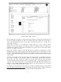
Wider applicability of database tools (e.g. an object browser can browse interface data). For
example, gure 5 shows the use of the EVE browser [20] to browse the instances of the EDEN
class tree, which is used to build hierarchically structured compound graphical objects).
Simplied application development environment (i.e. only one language, no impedance mismatch, references from application objects to interface objects, etc).
7
This latter feature can be illustrated using a simple example from geographic information systems.
An ADAM database was produced independently of the interface for storing low-level information
on roads, junctions and other boundaries for subsequent analysis [2]. A simple application of the
interface is to enable maps stored in the database to be drawn using the graphical interface. This
can be achieved by attaching a method called draw to each of the geographical objects which have
to be represented on the screen. For example, to draw the centre line of a road, it is only necessary
to retrieve its start and end points, create a new EDEN line object, and then to draw that line in an
EDEN picture object, as shown in gure 4.
class road {
attributes {
name: string;
start_junction: junction;
end_junction : junction;
...
}
methods {
draw(p: picture) {
l = line();
l.put_start(start_junction.get_point());
l.put_end(end_junction.get_point());
p.draw_line(l);
}
...
}
}
Figure 4: Fragment of geographical database schema.
The drawing of the gures on the map can then be achieved by creating a picture and iterating over
all the objects which have to appear on the map, sending them the message draw.
A simple map-drawing program which draws streets, junctions and street names has been written in
under 50 lines of EDEN code. Because the lines and text on the map are represented as database
objects, the map can be stored in the database along with the objects from which it was constructed,
and then redrawn simply by sending the associated picture the message open, which is quicker than
drawing the map from scratch (in this case, it takes about 5 times as long to rebuild a display as it
does to reopen it).
4.2 Extensibility
A principal feature of ADAM is that its data model can be extended with new constructs such as
relationships and composite objects, as described in [9, 19]. This extensibility at the model level places
new demands on direct manipulation database interfaces, which must provide eective visualisations
for the dierent categories of object described by the model. In eect, an extensible data model
requires an extensible interface [20]. This section outlines how the EDEN system has been used to
implement an extensible browser and manipulation system for ADAM called EVE (Extensible Visual
Environment).
EVE is itself an ADAM object, which contains references to a number of EDEN objects which are
used to present information and to interact with the user. The initial EVE display, which is shown
in Figure 5, is a collection of windows, which are represented by three EDEN objects for scrolling
through lists of names, and an EDEN picture object which is used to display part of the schema as a
graph. Each of the schema components drawn in the schema graph are drawn using EDEN objects.
8
Figure 5: Layout of EVE browser.
Further information is obtained by clicking on the names of items or on graphical visualisations using
a mouse. For example, clicking on an item in the schema graph using the left mouse button leads to
a form being displayed which is used to step through the instances of the class (e.g. the form used to
describe tree in gure 5).
Extensibility is supported at the interface level by allowing changes to the way in which dierent
categories of object are presented. For example, the way a relationship object is presented and
interacted with should not be the same as a composite object, as these object classes have dierent
roles and thus dierent semantics [4].
Extensibility becomes practical at the interface level only if the designer of the interface has provided
mechanisms which ease the modication of certain carefully identied parts of the interface. It is not
necessary to facilitate wholesale reorganisation of the interface in this case. All that is required is that
the ways in which dierent categories of objects are presented for direct manipulation are amenable
to modication.
In ADAM, the data model can only be extended with new constructs by experienced users, and
thus it can be assumed that the people who will need to develop new visualisations are competent
programmers. The ADAM data model is extended by revising the ways in which objects are created
by overriding default class creation operations at the metaclass level.1 It thus seems reasonable to try
to mirror the way in which extensions to the model are achieved when implementing extensions to the
interface. As the interface is implemented using the same object-oriented techniques as the database
system, this is also a practical approach to pursue.
For example, the standard way in which instances are displayed is shown in Figure 5, where an instance
of the class tree is being browsed. In an application it might also be required to browse instances of
1
A metaclass is an object which is used to specify the structure and behaviour of class objects [15].
9
classes which have been built using extensions to the basic model (e.g. ADAM has been extended to
support relationship [9], version [11], active-rule [12] and composite [19] object types, each of which
might reasonably be visualised using dierent techniques).
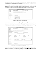
In what follows, it is assumed that the class settlement has been created as an instance of a special
relationship metaclass. The class settlement represents the relationship between a company and each
region in which it has oces. The settlement relationship itself has an attribute which is the number
of the oce in question. The default object visualisation for settlement is presented in gure 6.
Figure 6: Example default instance window.
The above visualisation of the relationship is, however, less than ideal, as it is the same as the
visualisation used for non-relationship objects. Thus, although the object has additional semantics
because it is a relationship, this is not evident from the visualisation. A revised visualisation for the
relationship is presented in gure 7, where the fact that settlement is a relationship is made explicit,
as are certain of the characteristics of the relationship (e.g. cardinality and constraints [9]).
Figure 7: Extended visualisation for relationship objects.
This can be implemented using overriding and inheritance, as suggested above. The default visualisation of an instance is created by sending the message new to the class eve instance form. To achieve
the alternative visualisation, a subclass of eve instance form is created with a revised denition of
10
new which performs the following tasks:
1. Send new to super, thereby creating a standard instance visualisation form without attribute
information.
2. Place the attributes on the form according to the revised layout.
3. Place additional information on the form which describes the meta-attributes of the relationship.
This approach enables the required change in visualisation to be achieved using a modest amount of
additional code, as most of the functionality in eve instance form has been reused. Similar approaches
can be used to modify other features of the display, such as the way in which the schema graph is
drawn, or the iconic representation of particular classes. Extensions to the interface can thus be
achieved within the context of a xed overall framework, using techniques similar to those which were
used to extend the data model.
4.3 Query Interface
EDEN has been used as the implementation platform for a multi-paradigm query interface [13], which
allows users to express queries over ADAM databases using a textual query language (Daplex [23]), a
form-based interface, or a graph-based interface. The interface also supports the translation of queries
from one paradigm into another. This section outlines how the query interface has been implemented
as an application of the EDEN toolkit.
The multi-paradigm interface is built around the four ADAM classes depicted in gure 8, namely
query mixin, daplex interface, graph interface and form interface. This class hierarchy allows the
functionality common to all the paradigms to be stored in query mixin and then inherited by the
specic interfaces. For example, all properties and operations relating to the generic internal representation of a query are dened in query mixin.
query_mixin
is_a
daplex_interface
uses
is_a
is_a
graph_interface
uses
form_interface
uses
EDEN Classes
Figure 8: Overview of classes used in query interface.
The visual representations required by the three existing paradigms are very dierent { the Daplex
interface requires an editor window into which the textual query can be typed; the form-based interface
represents each class of interest to a query as a form; the graph-based interface is based around two
picture windows, one depicting the database schema and the other the query. For example, gure 9
contains an example query expressed using the graph-based interface.
11
Figure 9: Example display from the graph-based interface.
Information associated with the display of a particular query interface is stored as properties of
the class used to model the corresponding paradigm. For example, in the case of the graph-based
interface depicted in gure 9, the class graph interface must reference the base window which contains
the interface, the gures which represent the schema, and the the gures which represent the query.
This is done by dening properties on graph interface which reference the EDEN objects which are
depicted on screen. As the EDEN objects are normal ADAM objects, their object-identiers can be
stored directly in the attributes of graph interface. For example, the following code fragment shows
part of the denitions of query mixin and graph interface:
class query_mixin {
attributes {
internal_form: set of query_component;
...
}
...
}
class graph_interface is_a query_mixin {
attributes {
picture_window: picture;
...
}
...
12
}
In the multi-paradigm interface, queries are represented internally using an object-oriented canonical
form represented using ADAM objects accessed through the internal form attribute of query mixin.
EDEN objects which represent the visual aspects of a particular interface are dened on paradigmspecic classes (e.g. the attribute picture window on graph interface). Furthermore, when the user interacts with the EDEN objects used to represent a query (for example, to extend the query graph), the
callback behaviour associated with the interaction can directly invoke the methods of graph interface
or query mixin, as both parts of the interface are implemented in ADAM.
5 Conclusions
This paper has shown how an object-oriented graphical toolkit can be fully integrated with an OODB,
in such a way that the database language is used to implement higher-level interface functionality.
Such a close integration of the interface with the database has a number of advantages over more conventional architectures { a single language is used for implementing the interface, the application, and
entensions to the data model; interface data can be stored in the database, and accessed/manipulated
using existing database facilities; the object-oriented facilities of the data model of the database can
be used for sharing useful interface data and for extending interface functionality.
Several examples of such extended functionality have been presented in this paper { a simple map
drawing program, an extensible direct-manipulation schema design tool/object browser and a multiparadigm query interface. EDEN has also been used to develop a debugger for an active rule system
[10]. The uniform representation of instances, classes, interface components and modelling constructs
as objects has thus been exploited to provide a powerful environment for the development of advanced
data-intensive applications.
Acknowledgements The second author is supported by a grant from the British Council and Arab
Student Aid International and the third by the UK Science and Engineering Research Council. We
are grateful to Alistair Kilgour, Oscar Diaz and Arturo Jaime for helpful discussions relating to the
topic of this paper.
References
[1] Laguna Beach Participants, Future Directions In DBMS Research. SIGMOD Record, 18(1), pages
17{26, 1989.
[2] A.I. Abdelmoty, M.H. Williams, and J.M.P Quinn. A Rule-Based Approach To Computerized
Map Reading. Information and Software Technology, 35(10):587{602, October 1993.
[3] G. Al-Qaimari. A Direct Manipulation Interface to an Extensible Object-Oriented Database. PhD
thesis, Computing and Electrical Engineering Department, Heriot-Watt University, Edinburgh,
Scotland, 1994.
[4] G. Al-Qaimari and N. W. Paton. Design and Evaluation of Visualisations for Advanced Data
Modelling Constructs. In C. Chrisment, editor, Basque International Workshop on IT (BIWIT),
pages 169{182. Cepadues Press, 1994.
[5] J. Almarode and T. Lougenia Anderson. GemStone Visual Interface Designer: A Tool for ObjectOriented Database Design. In Object-Oriented Databases: Analysis, Design and Construction
(DS-4), pages 73{94. North-Holland, 1991. W. Meersman et al (Eds).
[6] T. Lougeia Anderson, E. F. Ecklund, and D. Maier. PROTEUS: The DBMS User Interface as
an Object. In On Object-Oriented DB Systems, pages 139{156. Springer-Verlag, 1991. K. R.
Dittrich and U. Dayal (Eds).
13
[7] P.J. Barclay, C.M. Fraser, and J.B. Kennedy. Using a Persistent System to Construct a Customised Interface to an Ecological Database. In The 1st International Workshop On Interfaces
to Database Systems (IDS92), Glasgow, pages 225{243. Springer-Verlag, 1992. R. Cooper (Ed).
[8] Q. Cutts, A. Dearle, and G. Kirby. WIN Programmers Manual. Technical Report CS/90/17,
University of St. Andrews, 1990.
[9] O. Diaz and P.M.D. Gray. Semantic-rich user-dened relationship as a main constructor in
object oriented databases. In W.Kent R.A. Meersman and S. Khosla, editors, Object-Oriented
Databases: Analysis, Design and Construction (DS-4), pages 207{224. North-Holland, 1991.
[10] O. Diaz, A. Jaime, and N.W. Paton. DEAR: A DEbugger for Active Rules in An Object-Oriented
Context. In N.W. Paton and M.H. Williams, editors, Rules In Database Systems: Proceedings of
the 1st International Workshop, pages 180{193. Springer-Verlag, 1994.
[11] O. Diaz and N. Paton. Sharing behaviour in an object oriented database using a rule-based mechanism. In M.S. Jackson and A.E. Robinson, editors, Aspects of Databases - Proc. British National
Conference on Databases (BNCOD 9), pages 17{37. Butterworth-Heinemann Publishers, 1991.
[12] O. Diaz, N. Paton, and P.M.D. Gray. Rule management in object oriented databases: a uniform
approach. In R. Camps G.M. Lohman, A. Sernadas, editor, 17th Intl. Conf. on Very Large Data
Bases, Barcelona, pages 317{326. Morgan Kaufmann, 1991.
[13] D. K. Doan, N. W. Paton, A. C. Kilgour, and G. Al-Qaimari. A Multi-Paradigm Query Interface
To An Object-Oriented Database. 1994. To be published in Interacting With Computers.
[14] ECRC/ICL. ECLiPSe, User Manual, 1992.
[15] P.M.D. Gray, K.G. Kulkarni, and N.W. Paton. Object-Oriented Databases: A Semantic Data
Model Approach. Prentice-Hall International(UK), Hertfordshire, 1992. ISBN 0-13-620203-3.
[16] R. King and M. Novak. Designing Database Interfaces with DBface. ACM Trans. Information
Systems, 11:105{132, 1993.
[17] R. Marin, M. Taboada, R.P. Barreiro, J. Mira, and A. Delgado. Rapid Prototyping of Medical
Graphic Interfaces. In Proc DEXA, pages 161{166, 1992.
[18] R. Morrison, A. Dearle, A. L. Brown, and M. P. Atkinson. An Integrated Graphics Programming
Environment. Computer Graphics Forum 5(2), pages 147{157, 1986.
[19] N. Paton, O. Diaz, and M.L. Barja. Combining active rules and metaclasses for enhanced extensibility in object-oriented systems. Data and Knowledge Engineering, 10:45{63, 1993.
[20] N. W. Paton, G. al Qaimari, and A. C. Kilgour. An Extensible Interface To An Extensible
Object-Oriented Database System. In The 1st International Workshop On Interfaces to Database
Systems (IDS92), Glasgow, pages 265{281. Springer-Verlag, 1992. R. Cooper (Ed).
[21] N. W. Paton, R. Cooper, D. England, G. Al-Qaimari, and A. C. Kilgour. Integrated Architecture
For Database Interface Development. 1994. To be published in IEE Proceedings E, Special issue
on HCI.
[22] M. Schoning. A Graphical Interface to an Complex-Object Database Management System. In
The 1st International Workshop on Interfaces to Database Systems (IDS92), Glasgow. SpringerVerlag, 1992. R. Cooper (Ed).
[23] David W. Shipman. The Functional Data Model and the Data Language DAPLEX. ACM
Transactions on Database Systems, 6(1):140{173, 1981.
[24] F. States, E. Laenens, D. Vermeir, and L. Tarantino. A Seamless Integration of Graphics and
Dialogues within a Logic Based Object-Oriented Language. Journal of Visual Languages and
Computing, 1, pages 313{332, 1990.
[25] C. T. Wu. Benets of Object-Oriented Programming in Implementing Visual Database Interface.
JOOP, pages 8{16, March/April 1990.
[26] Z. Zhao. A Graphical Component Set for Database Interface Design. Technical Report, Computer
Science Department, Heriot-Watt University, Edinburgh, Scotland, 1990.
14