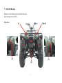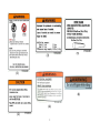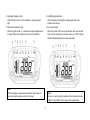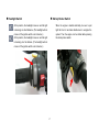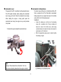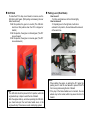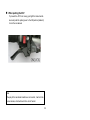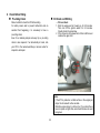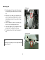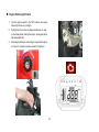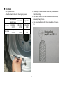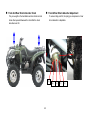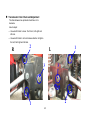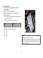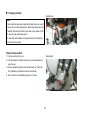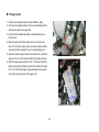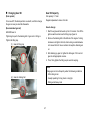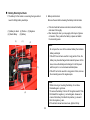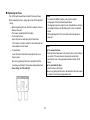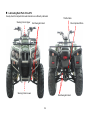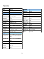
1
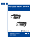
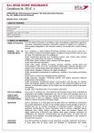
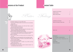
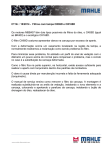
BEAR 400 UTILITY/ EFI 400 OWNER’S MANUAL Dear Customers, Thank you for purchasing BR400-UDI . This manual describes detailed instructions of correct operation, maintenance and adjustment of BR400-UDI. to ensure durable, safe and comfortable riding. In order for you to ride more safely and more comfortably, please read this manual thoroughly before riding it. Have a nice time riding! If data and relevant pictures contained in this manual differ from the real ATV, the data of the real ATV shall supersede data contained herein. 1. 2. 3. 4. 5. Important Message .................................................................. 1 Riding Precautions .................................................................... 3 6. Checks Before Riding ............................................................... 33 Attire; Check before Riding ........................................................ 4 Pre -riding Check; Oil Check and Refilling ................................ 33 Particular Attention on Parts That May Cause Burn; Load Recommended Oil Specification and Grade ............................. 34 Weight Limit ............................................................................... 5 Changing Oil ........................................................................... 35 Looking at the Terrain ................................................................ 6 Fuel Check and Refueling ......................................................... 36 Making Turns; Going Uphill ....................................................... 7 Front and Rear Brake Fluid Level Check and Refilling ............. 37 Going Downhill; Riding through Water ....................................... 8 Is Brake Performance Good? ................................................... 38 Naming of Each Component ..................................................... 10 Headlight Check; Headlight Beaming Distance Adjustment ...... 39 Operation of Each Component; Ignition switch .......................... 14 Engine Failure Light Check ....................................................... 40 Headlight Switch; Startup Rocker Switch ................................... 17 Tire Check................................................................................. 41 Accelerator Lever; Accelerator Limiting Device ......................... 18 Front and Rear Shock Absorber Check .................................... 42 Shift Stick; Parking Lever (Rear Brake) ..................................... 19 Transmission Chain Check and Adjustment.............................. 43 Flagpole holder; Steering Handle Lock ...................................... 20 To refill coolant .......................................................................... 44 Seat Lock .................................................................................. 21 Changing Coolant ..................................................................... 45 LCD Instrument Panel Adjustment............................................. 22 Filling Coolant ........................................................................... 46 Starting the Engine Electrically .................................................. 24 Changing Gear Oil .................................................................. 47 When Starting the Engine .......................................................... 25 How to Replace the Air Cleaner ................................................ 48 Normal Usage ........................................................................... 26 Spark Plug Check ..................................................................... 49 Normal Riding ............................................................................ 28 Simple Maintenance ................................................................. 50 Prolonged Engine Life Depends Upon Correct Riding............... 29 Regular Maintenance Table ...................................................... 51 When Applying Brakes, Simultaneously Apply Both Front and Battery Electrolyte Check .......................................................... 52 Rear Brake Handle Levers ...................................................... 29 Replacing the Fuse ................................................................... 53 Do Not Apply Emergency Brake and Have a Quick Turn........... 30 Lubricating Each Part of the ATV .............................................. 54 Riding with Particular Attention in Raining Days ........................ 30 When Failure Occurs ................................................................ 55 How to Stop the ATV; When the ATV Comes to a Full Stop ....... 31 Specifications ............................................................................ 56 When parking the ATV ............................................................... 32 Important Message Negligence of the following signs and warnings may cause serious damage and even death. Sign location (1) (2)&(6) (4) (3) (5) 1 (5) (3) (1) (6) (4) (2) 2 1. Riding Precautions Notes: 1. You should familiarize yourself with basic operations of this ATV before you try more difficult operational techniques. 2. To ensure the rider’s and others’ safety, anyone who drinks, takes drugs or medicine is not permitted to ride this ATV. The rider’s ability to control this ATV will be BR400-UDI ATV is a special multipurpose four-wheel motorbike with entertainment features. In this section, we will describe important notes and techniques in order for you to safely ride this ATV. Please read this manual thoroughly and spend some time practicing on your new ATV. Pay attention on your safety and that of others. reduced by the effects of medicine or alcohol. * If you do not have any experience riding an ATV, you can only ride it with instruction by a licensed or qualified instructor. First of all, you have to ride it slowly to feel and adjust yourself to the ATV, even if you are an experienced rider. * Do not attempt to utilize the maximum limits of this ATV. 3 Attire Check Before Riding To ensure safety, the rider shall wear a safety helmet, goggles, * Conduct gloves, boots and protective clothing when riding this ATV. a pre-riding check in accordance with “Check before riding” in user’s manual on Page 33 before riding to ensure safety and the service life of this ATV. * Your ability of controlling this ATV will be affected by insufficient tire pressure or a tire that is out of specification. Contact your service center for inspection to reduce the risk of an accident. 4 Particular Attention on Parts That May Cause Load Weight Limit Burn * The exhaust pipe and the engine become very hot when or after the ATV runs for a period of time. To avoid personal injury (including human and objects, etc), do not touch these parts. When the ATV is parked, also note that children or passers-by should not touch these parts to avoid injury. * To reduce the risk of fire, do not park this ATV near a dry lawn or flammable substances. Maximum allowable weight for this ATV is 150 kg (two riders) * When you carry loads on the ATV, slow down your speed to increase effective braking distance. * When you carry loads on the ATV, you should keep loads in balance to avoid loss of control of the ATV due to imbalance. Max weight 150Kg Notes: 1. Load weight limit: 150 kg 2. Exceeding the maximum load weight for this ATV may cause an accident. 3. When using this ATV as a trailer, slow down your riding speed. 5 Looking At The Terrain * Watch your speed and control technique when you ride on excessively flat, loose and rough surface, and keep an eye on any potential hazards such as pits, water puddles, rocks, root blocks, etc to avoid the risk of an accident. When riding with poor visibility, e.g. riding at night, turn on the headlight and slow down your speed to ensure safety. * When riding in the area where your viewing angle is limited, e.g. riding on a rough road in hills, it is advisable to attach a flag of some height in the rear of the ATV for warning purposes. This * can assure safety for the rider, other riders and onlookers. 6 Making Turns Going Uphill Note: When going uphill, move your gravity as forward as possible. Also, sit in the front part of the seat and bend your upper body forward. Keep a steady speed in the uphill process and keep the ATV balanced. When you approach a turn, first slow down and smoothly turn the handlebars to the direction you are going. Also, move your gravity to the outer floor panel and tilt your upper body to the inner side of the turn, which enables your control at the turn to be smoother and safer. Notes: 1. If the slope is too high to proceed and the ATV is moving backward, apply the front brake to slow down and carefully control the ATV to slip down. If it is beyond control, the rider should immediately get off from the left side to avoid the risk of being crushed by the ATV once it turns over. 2. Do not apply only the rear brake to avoid the ATV flipping over. 3. Do not abruptly apply the accelerator. 7 Going Downhill Riding Through Water Note: Place your gravity as backward as possible and straighten both of your arms. Keep the ATV in balance and apply the rear brake to slow down your speed. Watch the speed of water current and its depth if riding through water is necessary. If water flows very fast or is deep, the performance of the ATV will be affected, which may cause unsafely to the rider. Unless otherwise necessary, do not press the accelerator lever. Do not apply only the front brake to avoid the ATV flipping over. Notes: 1. Do not ride across a river with fast current or great depth to avoid loss of control of the ATV and cause risk of hazard to the rider. 2. After crossing the water area, you should check that the brake function is normal. If it is not, slow down your speed and also intermittently apply both front and rear brakes to restore the brake function. 3. If it takes a long period of time to ride through the water area and the brake system submerges in water too long, it will lead to loss of brake function. Do not ride this ATV any longer and take it to the nearest service center for inspection and servicing. 8 * Smoking is strictly prohibited when refueling the ATV. * Turn off your engine when refueling the ATV. 9 * Functionality of the ATV is dependant upon its structure. Any modification without our permission may cause performance degradation and in turn affect the service life of the ATV and riding safety. * It is illegal to modify this ATV without our permission. Do not attempt to make any modification. 2. Naming of Each Component 3 (1) Rear brake handle lever (include Parking lever) (2) Headlight light (3) Front brake handle lever (4) Right front turn signal light (5) Handlebar to lock (6) Left front turn signal light (7) Position light 1 2 7 4 6 5 10 (8) Right rear turn signal light (9) Left rear turn signal light (10) LCD instrument panel (11) Rear light / brake light (12) Exhaust pipe (13) License plate light (14) Battery 14, 15, 16 (15) Accompanying tools (16) Fuse 9 8 12 13 10 11 11 (17) Seat (18) Shift stick (19) Rear brake reservoir (20) Front & Rear brake fluid reservoir (21) Coolant reservoir tank (22) Radiator 17 ` (23) Right footrest (24) Left footrest (25)Throttle cable 19 25 18 21 23 20 22 24 12 (26) Ignition switch 27 (27) High/low beam switch Startup rocker switch Warning light switch Turn signal light switch Horn switch (28) Fuel tank cap 26 28 29 (29) Throttle Bottom Clamp (30) Rear brake pedal (31) Power Supplier-12V (32) Accompanying tools 30 31 13 32 3. Operation of Each Component Ignition switch 1. Reverse Indicator Light: The reverse indicator light comes on (red light) when you turn on the ignition switch, when the transmission is at the reverse gear. 2. Neutral Indicator Light: The neutral indicator light comes on (green light) when you turn on the ignition switch, when the transmission is at the neutral OFF : At this position, power supply to the ATV is completely cut off. The key can be removed. (The engine stops) ON : At this position, power supply to the ATV is connected. The key cannot be removed at this position. (The engine can be started up.) : At this position, power supply to the ATV is connected. The key cannot be removed and the headlight light comes on. (The engine can be started up.) (1) Key hole position. (2) Key Note: When starting the engine, the transmission should be at the neutral position to avoid any risk of hazard. Note: Do not turn the key to the OFF position while riding. This is the major cause of an accident. 14 3. High Beam Indicator Light: When this light comes on, the headlight is using high beam light. 4. Temperature Indicator Light: When this light comes on, it means the engine temperature is too high. Check the coolant level in the Aux Liquid Bottle. 5. Left/Right signal indicator: When operating the Left/right turn signal light switch, this indicator will come on. 6. Fuel level indicator: When the pointer of the fuel level indicator rests near the last scale, the fuel remaining in the tank is about 1.8 liters. Refuel with 95 unleaded gasolines as early as possible. Note: When the engine over-temperature indicator light comes on, Note: There is no need to add any additive to the fuel when refueling. Addition of any additive in fuel may cause engine failure. you must stop the engine and let it cool down. 15 7. Engine Failure Light: The Engine Failure Light comes on (red light) when you turn on the ignition switch. Starting the engine, the engine failure light extinguishment. 16 Headlight Switch Startup Rocker Switch : At this position, the headlight comes on and the light is beaming at a short distance. (The headlight will not come on if the ignition switch is not turned on.) : At this position, the headlight comes on and the light is beaming at a far distance. (The headlight will not When the engine is started electrically, be sure to pull tight the front or rear brake handle lever to energize the system. Then the engine can be started while pressing the startup rocker switch. come on if the ignition switch is not turned on.) 17 Accelerator Lever Accelerator Limiting Device To protect a new rider who is not familiar with this ATV from an accident, this ATV is fitted with an accelerator limiting device that can adjust the travel of the throttle valve, which in turn limits engine power. Adjustment: The speed of the ATV is controlled via the accelerator lever. The ATV speed increases when pressing the accelerator lever using your thumb. Press the accelerator lever slowly. When starting the engine or riding uphill, press the accelerator lever slowly, the engine revs up and produces more power. * To reduce the speed, release the accelerator lever. * Loosen the retaining nut, and then turn the adjusting screw with a screwdriver rider. Turning clockwise will reduce the travel of the throttle valve, while turning counterclockwise will increase the travel and increase the engine power up to its maximum. When the appropriate engine power is reached, tighten the retaining nut again. (1) (2) Note: The play of the accelerator lever should be 1 to 4 mm, which can avoid jerking ahead when the engine is started. ((1) Retaining nut (2) Adjusting screw 18 Shift Stick Parking Lever (Rear Brake) To make the ATV to stop, move forward, or reverse, use the shift stick to shift gears. (With pulling and releasing the rear brake handle lever) N: At this position, the gear is in neutral. (The shift stick must be at this position when the ATV is stopped or started) D: At this position, the engine is in forward gear. (The ATV moves forward) R: At this position, the engine is in reverse gear. (The ATV moves backward.) How to use it: ◎Turn the rear brake lever to the left side tightly. How to release it: ◎Pull parking lever to the right side, it will return automatic to its position, the rear brake will be relieved at the same time. Notes: 1. When starting the engine or parking the ATV, apply the parking lever to lock the rear wheels to prevent the ATV from moving and causing the risk of hazard. 2. If the play of the brake handle level is incorrect, the rear wheels may not be locked, which may cause the risk of a hazard. Notes: 1. The shift stick should be placed at the N position, when the engine starts up or stops to avoid the risk of hazard. 2. After the engine starts up, and when operating the shift stick, you should also pull the rear brake handle lever, or the engine will stop. This serves as a safe interrupting system. 19 Flagpole Holder Steering Handle Lock To prevent thefting, the handlebars can be locked when the ATV is parked. This allows you to position the desired flags in the holder. How to lock the handlebars: Turn the handlebars to the left all the way until it stops, and then turn the key clockwise to lock the handlebars. Then, remove the key. How to unlock the handlebars: Turn the key counterclockwise to unlock the handlebars, and then remove the key. LOCK K UNLOCK Notes: 1. After the handlebars are locked, verify that they are really locked by slightly turning them. 2. After the handlebars are unlocked, verify that they are really unlocked by rotating the handle. This can prevent risk of hazard when riding. 20 Seat lock The seat can be removed. The battery, fuses, and tool kit are located under the seat. How to mount the seat: Push the retaining tab under the front seat into the holder on the frame. Then push downward the rear part of the seat, and the seat can be attached on the frame. How to remove the seat: Pull the locking lever rightward, and then lift rear part of the seat backward. Now the seat can be removed. Note: After the seat is mounted, you need to ascertain that it is firmly attached to the frame by moving it upward/downward, and forward/backward. If the seat is not firmly attached, it may cause the rider to lose control of the ATV and lead to an accident. 21 LCD Instrument Panel Adjustment Indicator light Direction light(Green) ● Reverse(Red) R Engine Failure light(Red) ● Neutral(Green) N Watersymbol temperature Fuels light(Red) ● Drive(Green) Display range: 10levels. D The fuel reserve symbol begins ● to Gear flash if1(Green) only 3 grids1 High beam light(Blue) Adjust button fund ion left. In main screen press the Adjust button to switch to odometer, trip meter and the Max record. In trip meter screen, presses down the Adjust button for 3 seconds to reset the trip meter. In Max record screen, presses down the Adjust button for 3 seconds to reset the record. 22 23 4. Starting the Engine Electrically (1) Before starting the engine, first check oil and fuel levels. (2) Pull tight the front or the rear brake handle lever, or step on the brake pedal. Turn the ignition switch to the “ON” position. (1) Key hole Note: When starting the engine, the ignition circuit for the electric startup can only be energized with actuation of the startup switch in combination with the front or the rear brake handle lever being pulled tight or the brake pedal being depressed. (2) Key Note: When the ignition switch is turned on, check that the neutral indicator light comes on. The gear should be in neutral when the engine is started. 24 When Starting The Engine Press the startup rocker switch, and the engine can be started. * If the engine starts to cool, let the engine warm up for 2-3 minutes. * Do not rev the engine to high speed while it is idling. This can ensure the engine life. * Notes: 1. Once the engine starts to run, immediately release the startup rocker switch. 2. Do not press the startup rocker switch while the engine is running, or it will lead to an adverse effect to the engine. 3. Do not press the startup switch for over four seconds, when the electric motor is used to start the engine. 25 5. Normal Usage When riding: * The rear brake handle lever is kept at the braking position, and then put the shift stick to the “D” or “R” position. The rider shall put both of his feet on floor panel and keep his body upright with two hands holding the handlebars. Do not make haste, relax, carefully heed surrounding conditions and ride safely. Note: Note: When the engine is idling, do not push the accelerator to rev Before riding, the rear brake handle levers should be kept at the engine. braking positions. 26 Placing the parking lever back to its original position (OFF) is in the brake releasing (unlocking) status. Release the rear brake handle lever, and slowly push the accelerator lever, the ATV will start to run smoothly. Note: Note: After releasing the parking brake on the rear wheels, do not push Do not push the accelerator with force to avoid dash-out of the or press the accelerator lever to avoid jerking ahead and causing the risk of hazard. ATV. 27 Normal Riding The speed of the ATV is controlled via the accelerator lever. Make sure that the surroundings are safe before setting out on the trip. (See Riding Precautions) Pushing the accelerator lever ......... the speed increases The accelerator lever should be pushed slowly. When going uphill, slowly push the accelerator lever the engine will rev up and power increases. Return to original position............... the speed decreases. 28 Prolonged Engine Life Depends Upon Correct When Applying Brakes, Simultaneously Apply Riding * Both Front and Rear Brake Handle Levers. Keep the ATV speed no more than 40 km/h during the first month when new ATV starts to operate. (Engine running in period) After returning the accelerator lever back to its OFF position, firmly hold the brake handle levers and step on foot brake. * Ideally, when applying brakes, start to “slowly” pull the brake handle levers and then pull them firmly to the end. * Notes: 1. Care should be taken if applying only one brake handle lever on one side, it is easy to cause the ATV to skid and be unstable. 2. Do not attempt to apply emergency brakes during riding, it is easy to cause the ATV to skid, and is very dangerous for the rider. 29 Do Not Apply Emergency Brake and Have a Quick Riding with Particular Attention in Raining Days Turn * In raining days the condition of road surface differs from that in clear days. The brake distance will be extended. Ride at a lower speed and apply brakes earlier. * When going downhill, put the accelerator lever back to the OFF position and intermittently apply brakes. Ride at a slower speed. * Using emergency brakes and quickly turning are two major causes to lead to skidding and turning over, which is very dangerous for the rider. 30 How to Stop the ATV When the ATV Comes to a Full Stop Put the shift stick at the “N” position and turn the ignition switch to the “OFF” position. When approaching the parking space: * Check that the surroundings are in safe condition and then slowly park the ATV. * Put the accelerator lever back to the original position, and pull both front and rear brake handle levers, which will activate the brake light to alert coming ATVs in the back. (1) Key hole (2) Key Note: Turning off the ignition switch and removing the key during riding will cause the electrical system to disable. This is a major cause of an accident. Do not do that until the ATV comes to a full stop. 31 When parking the ATV: To prevent the ATV from moving, pull tight the brake handle lever and push the parking lever to the ON position (leftward) to lock the rear wheels. Note: If the play of the rear brake handle lever is incorrect, it will not lock the rear wheels, which will lead to the risk of hazard. 32 6. Check Before Riding Pre-riding Check Oil Check and Refilling Make it a habit to check the ATV before riding. For safety reason and to prevent malfunction and an accident from happening, it is necessary to have a pre-riding check. Even for a relatively simple and easy trip, a pre-riding check is also required. If an abnormality is found, ride Oil level check 1. Start the engine and let it warm up for 2-3 minutes. Then turn off the ignition switch for 2-3 minutes. Visually check the oil window. 2. If the oil level is at the lower limit, refill oil until the level reaches the upper limit. * your ATV to the nearest workshop or service center for inspection and repair. HI LOW Notes: 1. If the ATV is parked on a tilted surface or the engine just stops, the oil level will not be accurate. 2. When the engine stops, it is still very hot. If you check the oil level or replace oil right after, care should be taken to avoid being burn. 33 Recommended Oil Specification and Grade Oil specification: SAE 10W40# API.SL or above Engine oil grade: SL or above certified by API (American Petroleum Institute) Oil capacity: Full capacity: 1.6 liter Replacing volume: 1.4 liter Note: To prevent using low-grade oil, it is recommended you go to a workshop of the dealer from whom you purchased your ATV or the service center for oil change. 34 Changing Oil Oil filling cap 1. 2. 3. 4. 5. Start the engine and let it warm up for 2-3 minutes, and then turn off the ignition switch and remove the oil filling cap. Remove the oil pan drain plug at the bottom of the engine. Turning clockwise the plug to tighten it, and turn counterclockwise to loosen it. Use a container to keep the drained oil. After oil is drained up, tighten the oil pan drain plug. Then, fill in correct oil with appropriate volume. Visually check that the oil level is between the upper and lower limits. Then, tighten the oil filling cap. The tightening torque for the oil pan drain plug is 3.0 kg-m. Oil pan drain plug Note: To reduce the risk of getting burn, do not change oil when the engine is still very hot. 35 Fuel Check and Refueling Refuel Unleaded #92 or 95 as early as possible * How to use the fuel cap: 1. First stop the engine 2. Turning the cap clockwise you can open the cap, while turning counterclockwise you can tighten the cap. 3. When starting the engine, turn the ignition switch from the OFF to ON position. * Notes: 1. Smoking is strictly prohibited when refueling the ATV. 2. Stop the engine before refueling. 3. No need to add any additive in fuel when refilling. Addition of any additive may cause engine failure. 4. Do not top up fuel to the opening. Otherwise, fuel may spill (1) Key hole (2) Key Close OPEN as it may expand by heat or sunlight and lead to the risk of hazard. 36 Front and Rear Brake Fluid Level Check and Refilling Brake fluid refilling 1. Position the handlebars in the middle. Remove two fixing screws on the cover of the brake fluid reservoir, and then take out the cover. 2. Refill brake fluid, recommended DOT-4 grade, until it reaches the upper limit. Then, position back the cover and tighten two fixing screws. * Brake fluid level check 1. Position the handlebars in the middle. Check front and rear brake fluid levels in the reservoirs. Fluid level should be between upper and lower limits. 2. When the fluid level drops to the lower limit, check the condition of the brake shoe wear. * 3. If the brake shoe wear is within the specified limit, then it normally represents that there is leakage in the system. Ride your ATV to the dealer’s workshop or service center for inspection. 3. Change brake fluid once a year. Notes: 1. Do not mix brake fluid of different brands or grades, which may lead to brake failure and the risk of hazard. 2. When changing brake fluid, cover the painted area with cloth to prevent painted surface from being damaged by brake fluid. 37 Is Brake Performance Good? Brake Light Check 1. Turn the ignition switch to the “ON” position. 2. Pull both the front and rear brake handle levers to make sure that the brake light illuminates. 3. Check that the brake light housing is clean or damaged. Ride slowly to verify that the front and rear brake performance is good. 38 Headlight Check Headlight Beaming Distance Adjustment Headlight’s beaming distance is adjustable. 1. Turn the ignition switch to position. 2. Operate the headlight switch and check that the high beam or low beam illuminates. 3. Check that the headlight housing is clean or damaged. How to adjust it: Turn on the ignition switch and also turn on the headlight switch. Then screw in or out the adjusting screw to adjust the beaming distance. 39 Engine Failure Light Check 1. 2. 3. Turn the ignition switch to the “ON” position, the engine failure light comes on (red light). Pull tight the front or the rear brake handle lever, or step on the brake pedal, starting the engine, the engine failure light extinguishment. After engine starting or while riding, if engine failure light is on, take it to a dealer or service center for inspection. 40 Tire Check Is tire pressure OK? * See the following table when checking tire pressure. If metal chips or small stones are found in tire grooves, remove them before riding. * If tire crack is found or tire wear exceeds the prescribed limit, immediately change the tire. * If tire groove depth is less than 3mm, immediately change the tire. * Recommended standard value Lower limit Upper limit Front wheel 0. 28 kgf/cm2 3.92 PSI 0.25 kgf/cm2 3.5 PSI 0.35 kgf/cm2 5 PSI Rear wheel 0.28 kgf/cm2 3.92 PSI 0.25 kgf/cm2 3.5 PSI 0.35 kgf/cm2 5 PSI * 41 Front And Rear Shock Absorber Check Front & Rear Shock Absorber Adjustment Put your weight on the handlebars and rear hand rest and shake them upward/downward to check that the shock absorbers are OK. To ensure riding comfort, the spring pre-compression of rear shock absorber is adjustable. (5) 42 (4) (3) (2) (1) Transmission Chain Check and Adjustment The chain between two sprockets should have 3 cm clearance. How to adjust: * Use wrench 14mm to loose .1bolt 2.nut , both right and left side. * Use wrench 14mm to turn at clockwise direction to tighten the bolt, both right and left side. R 2 1 L 3 3 2 1 43 To refill coolant Normally do not open the radiator cap when the engine is still hot. 1. Park the ATV on a flat surface with stand. 2. Open the Aux Liquid Bottle and refill coolant until the level reaches the upper limit. * If the coolant level drops significantly, it usually represents a problem in the system. * Recommended anti-freeze: Te-she Anti-freeze Name Anti-freeze Prescribed concentration 30%(50% in cold zone) Concentration and anti-freeze temperature -12℃: 25% -15℃: -24℃: -35℃: 30% 40% 50% Notes: 1. Use soft water to mix with anti-freeze. 2. Note that low grade coolant will shorten the radiator service life. 3. Under normal conditions, coolant should be replaced once a year or every 10000km. 44 Changing Coolant Radiator cap Notes: 1. Care should be taken when opening the radiator cap, as coolant may be very hot with high pressure. Steam may cause burn and hazards. Wait until the radiator cools down. Use a piece of cloth to cover the cap and slowly open it. 2. In case that coolant drips on the painted surface, immediately rinse it with clean water. <How to drain coolant> Draining bolt 1. First remove the front cover 2. Push downward the radiator cap and turn counterclockwise to open the cap. 3. Remove the draining bolt and let coolant drain out. Tilting the ATV rightward may facilitate coolant to drain faster. 4. Take out the Aux Liquid Bottle and pour out coolant. 45 Filling Coolant 1. Position the draining bolt and Aux Liquid Bottle in place. 2. First fill up the radiator and then the Aux Liquid Bottle until the coolant level reaches the upper limit. 3. Ensure that the radiator cap and Aux Liquid Bottle cap are firmly closed 4. Start the engine and let the radiator fan run more than two times. Then stop the engine. (Be sure to wait until the radiator cools down before opening the cap, to avoid getting burnt.) 5. Open the radiator cap and check that coolant level is still at the upper limit, if not, refill coolant and then firmly tighten the cap. 6. Start the engine again and let it run for 1-2 minutes. Open the radiator cap and check that the coolant level is still at the upper limit, if not, refill coolant again. Keep repeating this procedure until coolant level can retain at the upper limit. 46 Changing Gear Oil Gear Oil Capacity (Drain period) Full capacity: 0.7 Liter Regular replacement volume: 0.6 Liter For a new ATV, the drain period is one month, and then change the gear oil every six months afterwards. How to change: 1. Start the engine and let it warm up for 2-3 minutes. Turn off the ignition switch and remove the filling cap of gear oil. 2. Remove the draining bolt at the bottom of the engine. Turning (Recommended gear oil) SAE 90# Gear oil Tightening torque for the draining bolt of gear oil is 2.45 kg-m Tighten the filling cap. clockwise is to tighten the bolt, while turning counterclockwise is to loosen the bolt. Use a container to keep the drained gear oil. 3. After draining up gear oil, tighten the bolt again. Fill in correct gear oil with appropriate volume. 4. Then, firmly tighten the filling cap to avoid oil seeping. (1) Gear oil filling cap Notes: Change gear oil more frequently under the following conditions: 1. Often riding in rain. 2. Usually operating for long hours or long trip. 3. Riding under heavy load. (2) Gear oil draining bolt 47 How to Replace the Air Cleaner Air cleaner cover A dirty air cleaner is the major causes of engine power drop and high fuel consumption. The air cleaner for this model is a wet sponge type. Check and replace the air cleaner every three months. Fixing clips (How to replace it) 1. Remove the seat 2. Unclip two fixing clips on the air cleaner cover and remove the air cleaner cover . 3. Loosen the screw and take out the cleaner core. 4. Replace the air cleaner core. Screw (How to mount it) * To mount it, take the reverse steps as above for replacing it. Notes: 1. If the air cleaner is not mounted correctly, dirt/dust may directly be drawn in the cylinder, causing engine wear, power drop and resulting in shorter engine life. 2. Do not wet the air cleaner when washing the ATV. Wet air cleaner may cause the engine to be difficult to start. 3. Check and replace the air cleaner at a shorter period under the following conditions: I. Often riding in rain. II. Often riding on the dusty road surface. Air cleaner core Clip Oil collecting pipe Note: Regularly drain off the accumulated oil in the oil collecting pipe under the air cleaner. Do not let accumulated oil exceed two-thirds of the pipe length. 48 Spark Plug Check Dirty pole or too wide a gap will cause incomplete sparking. <How to clean it> * Ideally, use a spark plug cleaner to clean it. * Or, use a needle brush to clean it. <Adjustment> * The gap between two poles normally is 0.6-0.7 mm as shown in Figure A. NGK CR8E (NGK) CR8E Do not use a spark plug other than a recommended one. A Notes: 1. When the engine stops, it is still very hot. Be careful not to get burnt. 2. First put the spark plug with hand tight, and then tighten it using a spark plug spanner. 49 Simple Maintenance If check results show that cleaning, adjustment and replacement are required. Conduct those operations in accordance with the description in the regular check record. Notes: Ensure safety when serving the ATV: 1. Use suitable tools. 2. Make preparation while the engine stops. 3. When the engine stops, the engine and exhaust pipe are still very hot. Care should be taken to avoid getting burnt. 50 Regular Maintenance Table Emission control system, checklist for serving items and timetable: For riding safety, keeping performance, prolonging ATV life, and reducing exhaust emission, you should inspect those service items for routine maintenance. I: Inspect, and clean, lubricate, refill, adjust or replace if required A: Adjust C: Clean R: Replace T: Tighten Item Lubrication System km 300 km R C Engine oil Oil strainer Gear oil Fuel supply Gasoline filter system Fuel strainer Fuel injection Fuel pipe Air supply system Air cleaner Secondary air cleaner Secondary air inlet system pipe Air inlet manifold screws Control related air pipe Catalyst converter Transmission Cam chain (4T) system Transmission chain (M/C ATV) Ride belt Valve gap (4T) Ignition system Spark plug/ 4T C.D.I Ignition circuit Others Important body bolts Brake system 1000 1500 2000 3000 4000 5000 6000 7000 8000 9000 10000 11000 12000 13000 14000 15000 km km km km km km km km km km km km km km km km R R R R R R R R R R R R R R R C I C C C C R R R R I I C C I/A I/A I I R R R R I I I I I I I I I I I I I I R I I I I T T T A T A T A T A T A T T A T A A A T A T A T A T A T A A T A Remarks I: Inspect A: Adjust C: Clean R: Replace T: Tighten *If cleaning, lubrication, refill, adjustment, or replacement are found necessary during riding or inspection, you can take corrective actions directly provided that exhaust emission is not seriously affected. However, it these have seriously affected exhaust emission, these corrective actions will not be conducted until they are reported for approval. (2) Maintenance other than planned schedule Item Ignition system Removing Deposit Transmission system Piston Cause for maintenance If abnormal ignition, engine over-heat, engine stall are found, immediately perform inspection. If engine power reduces significantly after operation of ten to fifteen months If power reduces significantly when accelerating after operation of ten to fifteen months If the engine is under severe load in the first month since operation, the piston, piston rings, cylinder may wear or get stuck. The engine should be cleaned or honed. Some parts may be renewed. 51 Battery Electrolyte Check 1. The battery for this model is a servicing-free type without need of refilling battery electrolyte. 2. Battery stud terminal Remove the seat before cleaning the battery stud terminals. If the stud terminal becomes corroded, remove the battery and clean it thoroughly. * After cleaning the stud, you may apply a thin layer of grease or Vaseline. Then, position the battery in place and attach the connecting wires. * (1) Battery tie band (2) Positive (4) Starter Relay (5) Battery (3) (1) (3) Negative (2) Notes: 1. Do not open the cover of the enclosed battery that contains battery electrolyte 2. If the ATV has not been used for a long period of time, the battery may have discharged and reduced its power. In this case, remove the battery and recharge it to its full power (5) and then put it in a cool and well-ventilated place. 3. If the ATV will not be used for a long period of time, remove the connecting wire at the negative pole. Notes: 1. While removing or mounting the battery, do not allow flammable gas to get close. 2. To remove the battery, first turn off the ignition switch. Then first detach the negative (-) connecting wire. However, to connect the battery, first attach the positive (+) wire and then the negative (-) wire. 3. If the terminal screw becomes loose, tighten it firmly. (4) 52 Replacing the Fuse Notes: 1. To replace the battery (lamps), use only the original components of the prescribed specification. 2. If components are not original or out of specification, the fuse can easily be blown, and the battery will not be in balanced status. 3. When washing the ATV, do not wash it with high-pressure water jet. Turn off the ignition switch and check if the fuse is blown. When replacing the fuse, always get a fuse of the specified rating. * Before replacing the fuse, first find out why it is blown. * Remove the seat * The fuse is located behind the battery * To remove the fuse: Open the fuse box and take out the blown fuse. If the fuse is not well in contact, it will create heat and easily leads to circuit failure. * To assemble it: Insert the fuse in the holder and position the cover back in place. Be sure to gently pull the fuse to ascertain that the fuse has good contact. A loose fuse will generate heat. * Notes: * To remove the fuse: Care should be taken when removing the fuse, as its holder is very small. If the fuse does not have good contact after opening the cover, it may generate heat and lead to circuit failure. * To assemble the fuse: Insert the fuse in its holder. Be sure to gently pull the fuse to ascertain that the fuse is well in contact. A loose fuse will generate heat. Fuse rating: 5A, 10A and 15A. 53 Lubricating Each Part of the ATV Visually check that all parts that need lubrication are sufficiently lubricated. Steering Column Upper Front Swing Arm Bush Steering Column Lower Throttle Cable Driven Sprocket/Chain Rear Swing Arm Bush 54 When Failure Occurs If The Engine Stops If the engine stops during riding, first check the following; * Is fuel available? * The way to start the engine is correct * Any failure occurs on other part If ATV experiences a malfunction during use, please take it to a dealer or service center for inspection. 55 Specifications Model BR400-UDI Dimensions Name BEAR 400 UTILITY EFI Overall length 2060 mm Overall width 1215 mm Engine Type Liquid-cooled, 4 stroke, 4 valve Overall height 1210 mm Cylinder arrangement Single cylinder, vertical Seat height 890 mm Displacement 359.3 c.c. Wheel base 1260 mm Bore x Stroke (mm) Ø78 x 75.2 Ground clearance 340mm Fuel Delivery Fuel Injection (FI), 35mm Claimed dry weight 266 kg Compression Ratio 11 Fuel capacity 14.8 Liter Ignition Digital TCI: Transistor Controlled Ignition Oil capacity 1.6 Lit. Starting System Electric Battery GTX12-BS Transmission CVT with reverse , H/L Gear Lubrication system Wet sump, Oil Pump Final drive Chain/Oil-seal Chain 520 Idle speed 1600±100 rpm Chassis Suspension / Front Dual A-arm with 5 way preload-adjustable shocks Suspension / Rear Dual A-arm with 5 way preload-adjustable shocks Brake / Front R/L Disc brake Brake / Rear Disc Brake Tire / Front AT25 x 8- 12 Tire / Rear AT25 x 10- 12 56