1
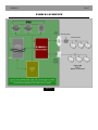
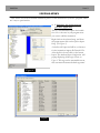
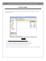
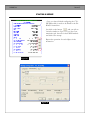
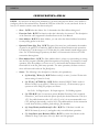
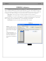
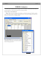
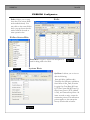
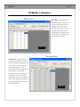
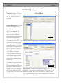
PAROCK1
(Modbus Master/slave serial/TCP Add on
Instruction for Rockwell’s Logix family PLCs)
User Manual
PAROCK1
PAGE 2
TABLE OF CONTENTS
Introduction...........................................................................................................................................3
Features List ..........................................................................................................................................4
PAROCK1 OVERVIEW ...................................................................................................................5
Quick Setup ...........................................................................................................................................6
Installation .............................................................................................................................................8
Serial Comm. Setup ............................................................................................................................ 10
Ethernet Comm. Setup ....................................................................................................................... 11
Configuration ................................................. ................... ............................................................... 13
Period/Cycle .................................................... ................... ............................................................... 13
Configuration Slave List ............................. ................... ............................................................... 14
Configuration Polls........................................ ................... ............................................................... 16
Polls, Config Par_Data ................................... ................... ............................................................... 16
Configuration Par_Data................................ ................... ............................................................... 18
Transactions ................................................... ................... ............................................................... 18
Data Cross reference ................................... ................... ............................................................... 19
Special Case Applications ............................. ................... ............................................................... 20
Advanced concepts........................................ ................... ............................................................... 22
Priority & Event Polling, Managing TCP Connections ....... ............................................................... 22
Scattered Read/Write, CFC-Custom/Private Function code ............................................................... 23
Dealing with ‘Processing’ Flag, Response time, Try 1 poll ..... ............................................................... 24
PAROCK1 Configurator ............................. ................... ............................................................... 25
Uttilities .............................................................................................................................................. 25
Polls, Polls-Status bits, System Data .................................................................................................... 27
Data X-ref, Transactions ..................................................................................................................... 28
Par_Data, Product Registration ........................................................................................................... 29
Options ............................................................................................................................................... 30
Function Codes Supported ............................................................................................................ 31
Diagnostics ......................................................................................................................................... 32
TABLE OF CONTENT
Error Codes......................................................................................................................................... 33
Action Commands ............................................................. ............................................................... 35
Suggestions, Tech Support ............................................... ............................................................... 36
Registration ........................................................................ ............................................................... 37
Disclaimer............................................................................................................................................ 38
PAROCK1
PAGE 4
PAROCK1
Applications supplied on Parijat distribution CD:
The distribution CD carries the following software products.
PAROCK1 Add-on instruction ( Parock1.L5X) (Rockwell CLogix import file).
PAROCK1 Configurator (Microsoft .NET application. Requires .NET framework 2.0 or later.)
User Manual (Parock1_um.PDF format).
INSTALLATION FOR PAROCK1 CONFIGURATOR
Starting Setup
1. Start windows (if it’s not already started).
2. Insert the PAROCK1 CD in the CD-ROM drive.
Set up wizard starts automatically
If Setup Wizard does not start:
1. Double-click the My computer icon.
2. Double-click the icon for the CD-ROM drive.
3. Double-click PAROCK1.EXE
Actual description of the PAROCK1 configurataor software application is later in the usual manual.
ASSUMPTIONS made about the Audience for this product & manual
1. Reasonably familiar with MODBUS (Learn more from www.modbus.org).
2. Reasonably familiar with Rockwell/Allen-Bradley ControlLogix (1756), CompactLogix (1769) or
FlexLogix (1794) PLC CPU family and RSLogix 5000 products. (Learn more from www.ab.com).
3. Reasonably familiar with basic Serial and TCP/IP communication (contact Parijat for more information) and PLC programming concepts. ([email protected])
4. Familiar with Microsoft Windows 2000 and later editions. Also, know how to use, install, and manipulate Windows applications.
PAROCK1
PAGE 5
INTRODUCTION
Parijat Controlware is very thankful to you for the opportunity to serve your needs.
PAROCK1 is an add-on instruction (the instruction) developed for Allen-Bradley/Rockwell
Logix family processors with firmware version 16 or later. (Contact Parijat for older versions’ solutions.) It provides an interface to external devices talking industry standard Modbus protocol in its various flavors via Channel 0 or Rockwell 17xx-EWEB modules for TCP/IP hardware interface. For direct serial interface you may use properly configured Channel 0. For TCP/IP, EWEB module is required, however, via TCP/IP switches and commercial TCP-to-serial adapters this may support several
serial communication ports and TCP/IP devices. (If you are using serial to TCP adapters, then the
hardware communication port settings of the adapter must match with the serial Modbus devices’ settings, for a successful project execution. The instruction does not play any role downstream of TCP-toserial adapter’s TCP port #, IP address for hardware interfacing. Use your adapter’s and Modbus device (s) user manuals to ensure compatibility. Endless possibilities exist for your applications with this
concept. It can be a Modbus master – polling several external slaves and/or it can be a Modbus slave,
being polled by external Modbus master devices. One instruction supports only one EWEB module.
You may share the same Par_Data (the array in the PLC that is the global data repository for all Modbus transactions) array amongst as many instructions by judicially demarcating regions in the array. You
are responsible for managing the use/sharing of this resource.
An external slave is a Modbus device physically external to the PLC system that shall be polled
for reading/writing of data by the instruction. In this case, the instruction may also be called working
as a Modbus Master. You may have as many external slaves polled, the PLC model’s limits apply.
An internal slave is applicable when the instruction is being polled for read/write by some
physically external Modbus device (s). In this case, the instruction may also be called working as a
Modbus slave. You can only have a single slave entity per instruction. If more than one slaves are configured, only the first one with lowest index in Slave_List shall be in use, the others shall be ignored.
For channel 0 serial interface, only one external master may be applicable. Theoretically you may have
more than 1 external serial masters but that may result in unpredictable scenario unless these multiple
external masters can ensure only one activity at a given time. Also, in channel 0 based serial systems,
you may not have both internal & external slaves in use simultaneously. Theoretically you may do it,
but severe practical limitations exist, obliterating any practical use of this scenario. Generally there is no
reasonable way to guarantee the fact that an external master’s request be treated as a response by the
internal master or vice versa. If you are using more than 1 instructions in a single PLC system, you may
use channel 0 serial interface only with one of these instructions. Unpredictable results may happen
otherwise.
Contact Parijat if any of the above conditions is affecting your application for alternative solutions.
PAROCK1
PAGE 6
FEATURE LIST
1. Contemporary Technology
2. Simultaneous support of serial and TCP/IP
3. Simultaneous Modbus master and slave support via TCP/IP.
4. Powerful TCP connection engine technology to efficiently manage and support TCP communication
5. Extremely low overhead on PLC memory and scan time
6. Quick start up and dynamically change configuration.
7. No duplication of data. Normalized design.
8. Automatic continuous diagnostics access to your logic and communication/time calculations.
9. View, transmit or receive messages online
10. Unlimited quantity of slaves supported for Master.*
11. Unlimited quantity of polls supported for Master.*
12. Enormous size of data storage (up to 758000 16-bit registers).
13. Prioritized and event polling.
14. Automatic scattered or continuous data moves for read/write.
15. Redundancy path support for communication to external slaves.
16. Custom/Private Modbus function codes support (in addition to Public FC 1,2,3,4,5,6,15,16).
17. Control and manage polls for failed slaves.
18. Uses native Rockwell hardware. (no 3rd party HW like Prosoft, Molex, FieldServer, etc.)
19. Fine-tuning of system can be very conveniently done.
20. Unlimited polls *
21.User Defined (Custom) Function Codes supported (up to 128)
22.Setup polls as FC’s or on action types.
23.Configuration is a part of the PLC program., no need to reconfigure HW when changing hardware.
24.Unlimited slaves (via TCP/IP) *
25.Configure multiples slaves with different properties
26.Priority poll action that can be dynamically set up/changed by user logic
27.Scattered read/write of contiguous data from/to slave on per poll basis
* Limited by PLC memory only.
PAROCK1
PAGE 7
PAROCK1 OVERVIEW
Figure 1
PAGE 8
PAROCK1
QUICK SETUP
In most cases a cross RS232 cable is used for single point-to-point communication. For long distance
runs and multi-drop scenarios, RS422 and RS485 communication is used with the appropriate converters
and wiring. Consult your converter’s manual for installation and setup details.
You may configure the following items for the instruction from either RSLogix5000 or Parijat’s PAROCK1 configurator application. To setup the instruction for use, update or enter the following data as
instructed below. The following steps apply to the PAROCK1 configurator application.
♦
Using Serial:
Configure the controller’s channel 0 serial parameters via RSLogix5000 to suit your needs for baud rate,
parity, etc. The mode on the serial port tab under controller properties must be set to “User”.
♦
Using TCP:
Configure the EWEB module through RSLogix5000 or RSLinx per Rockwell instructions; this usually
only involves setting the IP address.
In the configuration application, configure slave information by entering data on the slaves tab, configure
slave poll information on the polls tab.
♦
SLAVES
IP Address - For TCP slaves, set the slave’s IP address through RSLogix5000.
Port_Pri - For TCP slaves, set the slave’s IP port, usually 502.
RTU Address - Enter the slave’s RTU address.
Status - Click on the cell under the status column to view the current status and set the bits according to
your needs. Mandatory bits: set TCP/Serial, internal/external slave, enable bit suiting your needs.
♦
POLLS
Slave - Select the slave ID to which this poll should be directed.
FC - Enter the desired Modbus function code.
Start Address - Enter the address of the first register to read or write.
Quantity - Enter the quantity of registers to read or write.
Host Address - Enter the start index of Par_Data[], the global data repository, where registers will be read
to or written from.
Status - Click on the cell under the status column to view the current status and set the bits according to
your needs. Mandatory bits:- enable bit.
PAROCK1
PAGE 9
INSTALLATION
This section covers more detailed installation process of the instruction in your PLC program. There
are 2 ways to perform this.
♦
1. Importing the instruction into
your PLC application
This is a recommended option for installation. Go to the area in your program were
you want to add the instruction.
Right click on the selected rung, and from
the popup menu click on the option Import
Rung. (see Figure 2)
A window will open and will let you browse
for the instruction import file Parock1.L5x.
After the file is found, click on the button
Import. The window Import Configuration will
popup displaying all the tags as seen on
Figure 3. This tags can be renamed however,
this user manual assumes default tag names.
Figure 2
Figure 3
PAROCK1
PAGE 10
INSTALLATION
After you click OK on the screen Import Configuration the instruction will be added to the selected
rung as seen on Figure 4.
Figure 4
♦
2. Copying the instruction into your PLC application
Copy the instruction from another RSLogix5000 file into your program.
Create the UDTs and variables required manually in your PLC application.
Setup the IP related data as described in the main installation section.
This is a more involved way for installation than the first one & is more prone to errors/problems..
PAROCK1
PAGE 11
INSTALLATION
SERIAL COMMUNICATION SETUP.
For ETHERNET COMMUNICATION SET UP proceed to next page for instructions. Otherwise, for SERIAL Configuration follow these steps, using RSLogix5000.
Channel 0 Configuration set up and
installation
On the Serial Port tab, the mode has to be set to
User . The other settings can be configured according to your needs. In the example shown on
Figure 5, the settings are as follows:
Baud Rate = 38400
Data Bit = 8,
Parity = None
Stop Bit = 1
Control Line = No Handshake
RTS Send Delay = 0
RTS Off Delay = 0.
These settings must match the settings of the external device (s).
Figure 5
On the User Protocol Tab, the settings
have to be as follows:
Protocol: ASCII
Read/Write Buffer Size : 140 Bytes
Termination Character 1: ‘$r’
2:’$FF’
Append Character 1: ‘$r’ 2: ‘$l’
Delete Mode: Select Ignore.
Figure 6
.
PAROCK1
PAGE 12
INSTALLATION
ETHERNET COMMUNICATION
SETUP
If you are using TCP/IP, you should add the
appropriate 17XX-EWEB module(17xxENET, ENBT modules will NOT serve the
purpose of the instruction.). If you do not
have this module already installed, right click
on the option IO Configuration located on the
left hand side, and from the menu choose
New Module . (Figure 8)
This example assumes a ControlLogix CPU
with 1756 -EWEB module. For other PLC
CPUs, use equivalent EWEB module.
Figure 7
Click on Communications module and
select the 1756-EWEB module.
When you click OK, a window similar to
Figure 9 will appear. You need to fill up
the name and a valid IP Address. After
that this Module will be added to your
program.
Figure 8
Figure 9
PAROCK1
PAGE 13
INSTALLATION
Once you have finished configuring the 1756EWEB module, it needs to be linked to the PAROCK1 instruction.
Just click on the button
and you will see
a window similar to Figure 11. Go to the Communication tab browse for the EWEB module
and click OK to accept.
Repeat the operation for each ellipses in the
instruction.
Figure 10
Figure 11
PAROCK1
PAGE 14
CONFIGURATION
The instruction uses several user-defined type (UDT) variable structures to support itself. Do
not modify the structure layout of these UDTs as an unpredictable behavior may result. You may,
however, rename these UDTs to suit your needs. The user manual is assuming that the default names
are not changed. Some of the members are read-only and you should not make any attempt to write
into these read-only members data via your PLC application, as absolutely unpredictable results may
follow. It is highly recommended that the members that are writable by your application, may be written to, on a pulsed/one-shot basis. This reduces overall application scan-time and shall allow you to
“see” if some other activity is inadvertently affecting your data in any way. The instruction allows your
application to modify the slaves and poll characteristics dynamically (while the PLC application is running). This may wisely be done and appropriate considerations, like using the processing bit (status.12)
status, must be taken, as the instruction takes more than one PLC scans to complete its tasks. If you
want to dynamically change commsettings affecting the physical hardware (such as changing IP address, port#, internal/external slave type change, bit 4, 5, 10 in slave_list.status, etc.) then a reinitialize
command is also required (described in the Action Codes section). It is recommended that this type of
dynamic switching be done in a monitored mode several times, ensuring its satisfactory operation, before releasing to the production/target system. This is important as the variable factors and other dependencies impacts may be quite large.
You may also use active bit (status.29) for slave_list or Poll UDTs. Unless this bit is set, that
slave or poll is not used by the instruction. You may clear this bit, make changes and then set it for any
member of interest. This again may be done when the appropriate member is not active—in
“processing” (status bit 12 set). Affecting a member that is “processing” could result in an unpredictable result. The active bit 29 allows you to configure different scenarios in anticipation and then enforcing these when appropriate dynamically.
The instruction also may be conditionally enabled/disabled by your user PLC logic.
Period/Cycle- Used with internal master only. The time consumed in completing a polling
cycle starting with poll #0 to the highest poll # is cycle time. You may designate a quantity of cycles
over which efficiency should be calculated for communication and time spent (via Sys_Data in Action
Commands). This is called the period. Two types of efficiencies are evaluated. One is current or live
from the beginning of period to now. The other is efficiency of the last period.
Polling efficiency determines % of good polls over total polls. Time efficiency determines %
of actual transaction time spent as a % of timeout. This may allow you to fine tune timeout setting.
PAROCK1
PAGE 15
CONFIGURATION - SLAVES_LIST
•
Slaves_List - The array for the Slaves, lets you define or configure both internal
and external slave characteristics. It also allows you to monitor various status data
about the slaves. Create as many members as you need in your application. R/W
refers to Read or Write, RO is Read-only ability of user program for that member.
This configuration will apply to all transactions for this slave. Each member has
the following entries:
◊
Address - R/W Slave RTU Address (1-247). Applies to both internal and external
slaves.
◊
Port_Pri - R/W The TCP Primary Port Number. (For external slaves only)
◊
Port_Sec - R/W Specify the Secondary TCP Port Number. (For external slaves only)
◊
TimeOut - R/W Time out is measured in milliseconds. For Internal Slaves, it is processing time allocated for that slave and for external slave it is timeout. If this is set for less
than the maximum PLC scan time, then the actual delay is about less than 2 current PLC
scans. It is recommended that this should be about 3 times the maximum PLC scan time.
◊
Status (Bits) - Bit numbers are provided with description
•
(1) Healty (MBmstr)(RO) - Slave is healthy.
•
(2) Addressing Base (0,1) - R/W Minimum register/coil address is 0 or 1.
•
(3) RTU (0) / ASCII(1) - R/W Determines the MB type of the POLL, 0 for
RTU or 1 for ASCII.
•
(4) Serial (0) / TCP/IP (1) - R/W Determines if it is Serial or TCP/IP.
•
(5) MBTCP (0) / Embedded TCP - R/W Determines whether the POLL is
MBTCP (0) or if it is Serial MB Embedded in TCP (1). Embedded TCP allows you
to deal with a serial Modbus message embedded within a TCP packet or envelope.
•
(6) Swap Words (non Boolean) Lo Pri - R/W For 32 bit data it would use
IEEE-32 format (0) or not (1) and applies only to non-Boolean operations.
•
(7) Swap Bytes (non Boolean) Hi Pri - R/W For 16 bit data function codes
whether to swap (1) the bytes or not (0). Bytes are 8 bit grouped.
•
(8) Enable Swap - R/W Enable Bytes or Word swapping.
•
(9) Try only 1 poll if fail (MBmstr) - R/W This option will try only one poll if
any of the polls for this slave fails. More details provided in Advanced section.
•
(10) Ext.(0) / Int (1) Slave - R/W Selects an external or an internal slave.
PAROCK1
PAGE 16
CONFIGURATION - SLAVES LIST
•
(11) Redundant Port Avlbl (Mbmstr) - R/W Is only for master. If Redundant
port is available on the external slave and the option is purchased. Refer to Advanced Concepts section.
•
(12) Processing (RO) - Lets the user know that there is processing going on for
this slave now.
•
(14) 32bit Data type Address - R/W The current data type is 32 bits.
•
(24) Tried once (MBMstr) (RO) - This poll has already been attempted for the
current cycle. Refer to Advanced Concepts.
•
(25) Faulted (Mbmstr) - RO A fault detected with any poll of this slave.
•
(29) Active - R/W Set it in order for the this slave to start working.
◊
CommEff - RO Instantaneous Comm. Efficiency from beginning of period to now.
◊
CommEff_Last - RO Comm. Eff. Of the last period.
◊
Seq. Step - RO This is for the internal use, shows the current step in the sequence.
◊
Try - RO Total tries in current period.
♦
Try Good - RO The number of good tries in current period.
IP Address Pri. - R/W The desired IP address for TCP primary port of Slave. The IP
address should be part of the domain of the associated EWEB module.
♦
IP Address Sec. - R/W The desired Secondary IP address for Slave. The IP address
should be part of the domain of the associated EWEB module.
♦
♦
Connection ID - RO For the internal slaves, and is for internal use.
PAROCK1
PAGE 17
CONFIGURATION—POLLS
POLLS - You may have as many polls (members) as you want, and each one allows you to define or
configure polls for the external slaves. Extend the UDT size in the PLC to suit your needs. It also allows you to monitor various status data about each poll.
◊
Slave - R/W Index into Slaves List. It determines the Slave address being used.
◊
Function Code - R/W The function code that is desired to be executed. The description
of the Function codes supported is described later on the User Manual.
◊
Start Address - R/W With Start Address, you can select the desired address from where
to start polling points in the slave.
◊
Quantity Points (Qty_Pts) - R/W This part of the array lets you determine the number
of points to be polled. It is limited to 2000 for Boolean related function code operations.
It is limited to 67(16-bit integers or 33 32-bit data) for serial channel 0 multi integer operations. For TCP multi integer operations, the limit is 124 consecutive 16-bit or 62 32-bit
consecutive data registers.
◊
Host Address Start - R/W The Host Address Start is where you start reading or writing
into the PLC program’s Modbus global data repository Par_Data[]. For instance, for read
operation, if the host address you have set to 10, that means that the data will be stored
from index 10 in the Par_Data array upwards. For write operations, the data to write to
slaves will start at this index in Par_Data[] array.
◊
Status - The following is the description of the bits (# in parenthesis)
•
(1) Read (0) / Write (1) - R/W Defines read (0) or write (1) action. Works with
action setting of status bit 2 only.
•
(2) FC (0) / ACTION (1) - R/W Defines whether Poll[].FC field is used for
function code(0) or an action(1). When set as action(1) , set the memory type to
operate on in the Poll[].FC property as follows:
0 – Coils 1 – Digital inputs 2 – Input registers 3 – Holding registers
•
(3) CFC-R/W Sets if a custom or private Modbus Function Code is required.
Status bits 1, and 2 work with this option. Specify the desired Function Code (0 to
127). For public function codes 1,2,3,4,5,6,15, or 16 it is not recommended to use
CFC, although, theoretically you may use it. The additional data for the transaction
is read from the Host_Address_Start and Qty_Pts members.
•
(6) Swap Words (non Boolean) Lo Pri - R/W For 32 bit data it would use
IEEE-32 format (0) or not (1) and applies only to non-Boolean operations.
•
(7) Swap Bytes (non Boolean) Hi Pri - R/W For 16 bit data function codes
whether to swap (1) the bytes or not (0). Bytes are 8 bit grouped.
PAROCK1
PAGE 18
CONFIGURATION - POLLS
•
(8) Enable Swap - R/W Enables bytes or word swapping.
•
(9) Contiguous (0) / Scattered (1) - R/W Selects the mode of data processing/
moving. Applies if the option is bought. More details in the advanced section.
•
(12) Processing (RO) - Lets the user know that there is processing going on for
this poll.
•
(14) 32 bit Data Type Address - R/W The current data type is 32 bits.
•
(22) Priority - R/W It shows if it is priority Poll. See details in Priority section
•
(23) Event - R/W shows if it is an Event associated POLL. See details in Event
section.
•
(29) Active - R/W set it for the POLL to start working.
◊
CommEff - RO Current period instantaneous Comm. Efficiency. Since beginning to now.
◊
CommEff_Last - RO Shows the efficiency of the last period.
◊
TimeEff - RO Current period’s Comm. Time Efficiency since beginning period to now.
◊
TimeEff_Last - RO Last period’s Comm. Time Efficiency.
◊
Try - RO Total tries in current period since beginning.
◊
Try Good - RO number of Good tries in current period.
PAROCK1
PAGE 19
CONFIGURATION—PAR_DATA
♦
Par_Data
(INT type) is an 16-bit array you can use as global data repository. Your application can read
or write data from this array. If certain data elements overlap, per definitions in the poll members,
then the results of the contents will be governed by last actions. It is not recommended that you stuff
analog/integer data & Boolean/digital/bits data in the same word that is part of 2 different polls for
updating. Both internal and external slaves rely on this array for data. The instruction reads and writes
data from this array as it deems fit and when it deems fit. Typically, this action is performed when
read or write action has to be executed. As such, the last or current contents of the array are used. In
time sensitive applications, you may monitor the “processing” bit before reading or writing to the appropriate members of this array.
In master mode, the instruction keeps the appropriate members of this array updated as the
instruction reads data from the external slaves. It reads data from the appropriate section of this array,
when a write operation has to be performed on any external slave.
In slave mode, any external masters reading data, access this array. The external masters write
data into this array.
Any Boolean Modbus function code operations are always handled as packed-bit operations.
Each member of this array supports 16 consecutive bits. The bit number increases from the 0th bit
(LSB) of the base word to 15th bit (MSB) in the base word to higher bit addresses in the adjacent increasing words. You may deal with up to 2000 contiguous bits in a single Modbus transaction.
Support for 32-bit type data is provided by using 2 adjacent registers. You may treat it as an
integer or floating point data. Byte level and word level swapping is supported. String type data shall
be handled by your application, packing up to 2 byte characters (8-bits each) in one 16-bit members of
this array.
TRANSACTIONS
If transaction logging is on, this shows related data for that transaction. The pointer in system
data (described in Action Commands) points to the last member that was updated in this circular
buffer. You can create as many transaction UDT members.
♦
Slave - It determines what Slave is being used.
♦
Poll FC - Poll ID for external slave & function code for internal slave.
♦
Error Code– 0 means good and non-zero is the error-code.
♦
Transaction Time— It shows the time for the transaction in milliseconds.
PAROCK1
PAGE 20
CONFIGURATION—DATA CROSS REFERENCE
This is used with scattered mode and is not available for Boolean function code(1,2,5) opera
tions. For each poll, you define the source index, the destination start address, as a Xreference.
♦
Poll - It defines the poll ID.
♦
Source - the 0-based Source Register index. For reads from ext slaves, refers to read block
in slave. For writes, it refers to global data repository.
♦
Destination - the 0-based index for destination array. For reads from ext slaves, it refers
to global data repository & for writes, it refers to slave data block.
♦
Quantity - It shows the quantity of registers. Minimum value is 1, maximum is whatever
allowed by the max quantity for the related poll. If you enter illegal data, unpredictable results may follow.
More than 1 entries are allowed for any poll. The members for a poll do not need to be consecutive or in any order. The execution order is always from index 0 of this UDT to the highest for a certain poll. You must verify that there are no overlaps & user-entered data is valid/
legal for your configuration. Any gaps in data for reading from external slaves, will leave the
Par_Data unchanged. Any gaps while writing to ext slaves will result in clearing the gap register addresses to 0. The figure below illustrates an example of scattered write operation.
Figure 12
PAROCK1
PAGE 21
SPECIAL CASE APPLICATIONS
General Comments
During dynamic configuration changes, care should be taken when setting bits of interest in a
word (Poll & Slave_List status) that other bits should not be affected. You may also give a serious
thought to changing other items that may be related in the same PLC scan. These changes should
only be enforced when “processing” (status.12) bit in appropriate section is off/clear.
INTER-POLL DELAY VARIABILITY
If your application needs a polling interval that varies poll to poll, you can accomplish this by
changing the inter poll delay before desired poll invocation. This Instruction does not change the inter-poll delay. So, the last value of inter-poll delay will prevail. This may be a valuable tool if you
need to conserve overall system communication bandwidth.
Different slave characteristics on same drop
If external slave characteristics vary from slave to slave, you may handle this situation by varying the status bits of the intended external slave before it goes in “processing” mode. Any of the legal
status bits or other variables in the Slave_list UDT may be manipulated. The baud rate, parity, stop
bits and other communication port hardware related configuration can not be dynamically changed on
a given port - be it Channel 0 or downstream ports on TCP/Serial adapters.
PAROCK1
PAGE 22
SPECIAL CASE APPLICATIONS
…………This page intentionally left blank………..
PAROCK1
PAGE 23
ADVANCED CONCEPTS
This section is for more experienced users
and may be used after comprehension
♦
Priority and event polling
Priority Poll may be invoked by setting bit 22 of any active poll status word. One or
more priority polls may be invoked at any given moment.
Event polls (also referred to as Demand polls) are a group of significant active polls
that may need to be executed in a succession, associated with any event that your control sys
tem detects or generates. This may be accomplished by setting bit 23 of the appropriate poll (s)
status word that are associated with this event. Event polls have a lesser priority than the typi
cal priority poll.
This feature should be used with caution as it affects the normal polling mechanism, by
ing
delaying the normal polls till priority/event poll processing is finished. Preferably use one-shot
type method to set the priority/event flag bits where appropriate. Before invoking a normal
poll, the instruction evaluates to see if any priority or event poll is scheduled. It finds it by startfrom the 0 member, proceeding to the last member in the poll UDT. As it executes the prior
ity/event poll, the appropriate flag in that UDT is cleared. After the last priority/event poll is
finished, the instruction resumes from that member onward for its normal polling. This may
result in missing some of the normal polls of current cycle that may be interspersed in
between one or more of the priority or event polls.
♦
Managing TCP Connections
Parijat designed unique method to manage multiple TCP connections for the EWEB
module. This allows the PLC to dynamically and very efficiently add and drop TCP
connections for devices outside the EWEB module. As new device (s) try to establish
connections with the EWEB module, appropriate resources are allocated for the connection.
If a connected device decides to drop out or disconnect for whatever reason, the resources are
automatically de-allocated. There is a max limit (imposed by EWEB) on the quantity of
simultaneously active connections. If this limit is reached, new device connections are denied.
This also regulates the flow of queries and responses between various devices and the PLC.
This allows for the maximum use of what is available from the EWEB module and provides
the most efficient connection throughput.
Each external MB TCP slave and each TCP/serial adapter’s IPaddr/port combination
consumes a TCP connection from EWEB. For internal TCP slave, one connection is used for
the listen port & each external TCP master consumes a connection. A connection is
automatically dropped for communication inactivity time of over contiguous 5 minutes or so.
PAROCK1
PAGE 24
ADVANCED CONCEPTS
♦
Scattered read/write
This feature (only for external slaves multi-register non-boolean operations, e.g. function codes 3,4,16) allows you to read/write data in a scattered way into global repository. When you
read/write data, it is sent/received as a contiguous block of data ordinarily. This feature also allows
you to distribute the read data from or data to write to external slaves, into non-contiguous blocks in
Par_Data. The scattered feature is configured using the Data_Xref (UDT), described later. The contents must be within the legal ranges of arrays configured in the PLC system, otherwise unpredictable
operation may happen, including a CPU fault. If gaps exist in the data range, that data in destination
defaults to 0 or no change, refer to Data Xref(UDT) for more details. If overlap exists, the last action
prevails. It is recommended that you use Parijat Configurator to configure this feature. The instruction
processes the data using Data_Xref from element 0 to the top, seeking the Poll (.ID_poll) that is being currently processed. The Source address (.ID_Src) refers to the register offset address for the
source. The Destination address (ID_Dstn) refers to the Register offset address in the destination.
The (.Qty range 1-124) is the quantity of registers for this transaction. The scattered operation adds
extra processing time to the operation.
♦
CFC – Custom/Private Function Code support.
Modbus function codes 1,2,3,4,5,6,15, and 16 are considered to be public. The instruction supports all of these public function codes. Also, you may define your own user-defined,
custom or private function codes. The appropriate option must be installed and purchased. In
the Poll.Status word, set bit 3 to invoke this. Set the function code in Poll.FC. The rest of the
data to create this message is used from the Host_Address_Start and Qty_Pts as 2 ASCII
packed characters from each 16-bit word in order.
PAROCK1
PAGE 25
ADVANCED CONCEPTS
♦
Dealing with ‘Processing’ flag
Bit 12 of Slaves_Data and Poll status member is 1 during the time that entity is actively
in use by the instruction. The ideal time to dynamically alter any related data for the polls or
slaves, should be done when this bit is 0, otherwise unpredictable results may occur.
♦
Response time
The instruction will try to execute & complete polling a certain external slaves (as a
Master), if any, in 1 to 2 scans of the PLC before transmission of outgoing message. The wait
time for response to be received from external slave is beyond our control, as so many vari
ables play an active roll – like media type, physical distance, noise, external device(s) processing
delays etc. Once full message is received from external slave, full processing is completed in
one PLC scan. An internal slave is always at the mercy of external masters. At the end of every
master poll, if configured, evaluation for internal slaves is done. Any requests from external
masters is processed before scheduling next poll. A serial channel 0 internal slave may consume
2 -3 PLC scans for processing this & sending the response to the external master. The TCP
internal slave may consume more scans to process this request from each of the external mas
ters who have pending requests. If no pending requests are there for the internal slave, system
waits for the inter-poll delay before invoking next poll. For this reason, the external masters
rate of activity & their quantity typically determine the impact on
the performance of the
instruction on the overall PLC scan time.
♦
Try only 1 poll (Slave_List.status.9)
An external slave may have several polls configured in the instruction. If a
communication problem arises with this slave, the instruction waits till timeout occurs. This
may impact the rest of the system turn-around response. In fact, every poll for such a slave is
going to wait for timeout, delaying the rest of the system activity & response. If this presents
response-time problem in your application, you may set this bit. By doing this, the instruction
shall only try to communicate with this slave only once in a poll cycle. The other polls shall be
ignored till the communication problem is resolved. This feature/bit is not used by internal
slaves.
PAROCK1
PAGE 26
PAROCK1 Configurator
Configurator (also called PAROCK1 Configurator) is a Microsoft Windows application to configure or debug the PAROCK1. It requires .NET framework 2.0 or later. After making any changes to
the size of any arrays or configuration in the PLC related to PAROCK1, you may need to re-launch the
Configurator. The UDT size changes are only read from the PLC at launch of the Configurator.
Error code - Shows the last error code and its description from the instruction.
IP Address - Enter the IP Address of the PLC Ethernet communication module. This should
generally be the same as you may use with RSLinx for your RSLogix 5000 application. If the IP Address is changed, click on the Refresh button. The last IP address is memorized.
Slot Number Enter the slot number where the PLC-CPU is located.
Utilities
Utilities - It allows you to invoke commands and view the
results in the Value section of
grid on the left of the application.
Action Commands - Lets
you pick a command for invocation. The detailed action
commands are described elsewhere
Figure 13
PAROCK1
PAGE 27
PAROCK1 Configurator
The white cells are editable, however, the gray cells are not editable. You may click on the status of
the Slaves & Polls to view/edit various bits also in a pop-up window.
Various Tabs are described herein.
Slaves - Data such as, the address, the Port Primary, and Port Secondary, the TimeOut, and the
status of the Slaves, and the CommEff, CommEff_Last, Try, Try_Good, IP Address_Pri and IP Address_Sec. Is shown here for viewing & editing.
Figure 14
Slaves-Status Bits—Figure 15 shows the status bits
of the slaves, as you can see, the value for each bit is
show on this pop up screen.
Figure 15
PAROCK1
PAGE 28
PAROCK1 Configurator
Polls—Allows you to setup
slave data. The various fields
are described already. You
may click on the status field to
have a pop-up shown that describes each bit for read or
write operation also.
Polls
Polls—Status Bits
Status Bits— Figure 17 shows the description of
each bit being used at the Polls.
Figure 17
Figure 16
System Data
Sys Data– It allows you to view or
edit the following:
Inter-poll delay (milliseconds).
Tries limit for efficiency calculation,
Start Offset in Par_Data, Xsaction
Logging On, Clear Data @ Power
Up, Clear Comm Eff @ Power Up,
Slave Listen Port # (TCP) (default
is 502), and Transaction pointer. All
items are read or write, except the
transaction pointer. The transaction
pointer applies to the transaction
history circular table or buffer.
Figure 18
PAROCK1
PAGE 29
PAROCK1 Configurator
Data X-ref
Data Xref - used with Scattered data option. Allows you
to set the scattered data configuration. Do not enter a
number that points to nonexistent data in the PLC, as
unpredictable operation may
result. Refer to the Scattered
data section for details.
Figure 19
Transaction
Transaction - This section is
read-only. It will show transactions if transaction logging is set
to on. If not, it shows the last
transactions history. If set, it
shows what slave is being used,
the poll# for ext slave/the
function code that is being used
for internal slaves , the Error
Code if any and the Transaction
Time. The transaction pointer (in
System Data) points to the member last updated.
Figure 20
PAROCK1
PAGE 30
PAROCK1 Configurator
Par_Data—Figure 21 shows
the contents of Par_Data array, the global repository of
user data.
Product Registration—Use this
section of the application to
register your product with Parijat
and also to know what options
are currently installed. The
instruction is always provided in
demo/trial mode. This timelocked mode is a fully functional
mode for the trial period of
about 2 hours after a program-to
-run transition of the PLC. You
need to use the Parijat Configurator application to unlock/
register the product, as is shown
in Figure 22 . The registration is
done on a per PLC CPU basis.
Other options are available,
contact Parijat for details.
Par_Data
Figure 21
Product registration
After you purchase the product,
contact Parijat and provide the
Code to Parijat. The sales person
will provide you with the registration code.
You enter the registration code
provided & click on register.
Product configuration will show
the options you have currently
installed in the PLC. Read Options section for more details.
You MUST save the PLC project
after this activity.
Figure 22
Next release : To transfer the registration from a PLC to another PLC. This option is available, however, once you move the
software to another PLC, the license will be moved to the new
PLC, leaving you with a demo version on the previous PLC from
where you removed the license.
PAROCK1
PAGE 31
OPTIONS
♦
Serial Master via Channel 0
This is the basic option for the instruction. It works as a Master (supporting external slaves
polling).
♦
TCP via EWEB
Supports TCP/IP communication.
♦
Slave
It works as a Slave (being polled by external masters).
♦
Redundancy
This option (only for TCP/IP based systems) allows you to specify a secondary IP address
and port number for external slaves. If there are any errors/problem detected with communicating
with that external slave, the secondary IP address/Port number is switched to, after an error is
reported. Every poll, the instruction attempts to communicate using the primary path, if it succeeds,
that path is resumed or used, else the secondary path is used. If both fail, an alarm is generated.
This option does not apply to internal slave. The IP addresses should be part of the domain of the
associated EWEB module.
♦
More than 5000 registers
Supports for more than 5000 registers for the global repository. The upper limit is dictated
by the PLC model & its memory. Typically a 1.5M limit is set for Clogix processor that translates to
a maximum of about 758000 16-bit INT registers.
♦
CFC support - (Custom/Private Function Codes): See Advanced Concepts section for
more information.
♦
Scattered Mode—See Advanced Concepts for more details.
♦
Site License - Allows you to have unrestricted copies for your site.
♦Bundled with EWB module
You may also procure the PAROCK1 from Parijat bundled with appropriate Rockwell EWEB module.
Support Agreements—available for this product.
Contact Parijat for further details.
PAROCK1
PAGE 32
FUNCTION CODES SUPPORTED
♦
01 Read Coil Status Reads the ON/OFF status of discrete outputs (0X reverence, coils) in the slave.
♦
02 Read Input Status Reads the ON/OFF status of discrete inputs (1X reference) in the slave.
♦
03 Read Holding Registers Reads the integer contents of holding registers (4X references) in the slave.
♦
04 Read Input Registers Reads the integer contents of input registers (3X references) in the slave.
♦
05 Force Single Coil Forces a single coil (0X reference) to either On or OFF.
♦
06 Preset Single Register Preset a value into a single holding register (4X reference).
♦
15 (0F Hex) Force Multiple Coils Forces each coil (0X reference) in a sequence of coils to either ON or OFF.
♦
16 (10 Hex) Preset Multiple Regs Preset values into a sequence of holding registers (4X references).
PAROCK1
PAGE 33
DIAGNOSTICS
♦ Serial (Channel 0) or TCP Embedded:
You may need RS232 hardware handshaking troubleshooting hardware to verify your cable
wiring. Typically a cross serial cable is required between the PLC and the other serial device. You
may contact Parijat for a Serial Comm. Testing utility.
♦ TCP
If you do not have a need or are not using a switch/router, use a cross Ethernet cable,
otherwise use a straight Ethernet cable. Hardware troubleshooting tools (available from Black Box,
B & B Electronics, etc) may be used to verify cable and connections. Then using a PC you should
ping both IP addresses of master as well as slave.
To check the connections and types of connections use the built-in Web-server of the
EWEB module. (Refer to Rockwell user manual). The listen, client, and server ports should be
active, with correct IP addresses and port numbers displayed; if not, investigate. The IP listen port
(defaults to 502; may be changed via system data settings) is used by the internal slave to listen for
external master communication activity. All external masters must be configured to connect to this
IP and port. The refresh rate of the EWEB diagnostic page should always be greater than zero.
You may also employ products like WireShark, to help you troubleshoot TCP/IP
communications.
Parijat also sells a Microsoft Windows based utility called Modbus Analyzer to aid in
troubleshooting of Modbus networks.
PAROCK1
PAGE 34
ERROR CODES
FATAL ERRORS
A Fatal Error aborts the current transaction and is reported in Code Error and also in
transaction history log, if logging is enabled. Keeping logging on, does not have noticeable impact on
system scan time.
♦
01 FUNCTION CODE (FC) UNSUPPORTED
♦
21 SCATTERED MODE WITH BOOLEANS
♦
02 ILLEGAL REGISTER ADDRESS IN
REQUEST
♦
22 ILLEGAL DATA ADDRESS IN
TRANSMIT SCATTERED MODE
♦
03 FUTURE-ILLEGAL DATA VALUE
♦
♦
04 SYSTEM FAULT
(NONFUNCTIONAL/UNREGISTERED
UNITE)
23 ILLEGAL DATA ADDRESS IN RECEIVING SCATTERED MODE
♦
24 ILLEGAL ASCII MODE SELECTION
♦
25 ILLEGAL USER ACTION CODE RECEIVED
♦
05 FUTURE ACKNOWLEDGE
♦
06 FUTURE SLAVE DEVICE BUSY
♦
♦
07 FUTURE NEGATIVE ACKNOWLEDGE
26 ILLEGAL RTU ADDRESS IN RECEIVED MESSAGE
♦
27 ILLEGAL RTU ADDRESS IN POLL
♦
08 FUTURE MEMORY PARITY ERROR
♦
28 ILLEGAL POINT QUANTITY
♦
16 ILLEGAL FUNCTION CODE IN MESSAGE
♦
29 ILLEGAL HOST REGISTER ADDRESS IN
REQUEST
♦
17 CRC/BCC ERROR IN RECEIVE MESSAGE
♦
30 ILLEGAL SLAVE REGISTER ADDRESS
IN RESPONSE
♦
18 TIMEOUT BEFORE GOOD RESPONSE
♦
31 POLL & SLAVE TYPE (32-BIT) MISMATCH
♦
19 MB MASTER - PRIMARY & SECOND
PORT FAILURE
♦
32 NO TCP CONNECTION AVAILABLE
♦
33 ILLEGAL IP ADDRESS
♦
20 MBMstr-NO SLAVE FOUND TO POLL ♦ 34 BOTH MASTER & SLAVE SELECTION
FOR SERIAL COMM.
PAROCK1
PAGE 35
ERROR CODES
SERIAL PORT ERROR CODES
♦
62 THE MODE WENT OFFLINE
♦
63 THE CTS SIGNAL WAS LOST DURING COMMUNICATION.
♦
64 THE SERIAL PORT WAS IN SYSTEM MODE.
♦
70 UL BIT WAS SET. PREMATURE TERMINATION.
♦
72 PLC CHANGED FROM RUN TO PROGRAM MODE DURING EXECUTION.
♦
73 BUFFER SIZE OR ECHO MODE PARAMETERS CHANGED DURING
TION
♦
74 THE ACL INSTRUCTION EXECUTED AND STOPPPED OR REMOVED THIS TYPE
OF INSTRUCTION.
♦
75 USER MODE TO SYSTEM MODE CHANGED
EXECU-
TCP ERROR CODES
♦
91 IP ADDR OR PORT # BAD
♦
92 FAILED TO CREATE SOCKET
♦
93 OPEN CONNECTION TIMEOUT OR REJECTED
♦
94 FATAL CONNECTION OPEN ERROR
♦
95 READ ERROR
♦
96 WRITE ERROR
NON FATAL ERROR MESSAGES
Non-Fatal error is informational only and transaction continues. It is also reported in codeerror and in transaction logging.
♦
110 TCP PORT SWITCHED
♦
111 TCP MESSAGE ID MISMATCH
PAROCK1
PAGE 36
ACTION COMMANDS
The action commands are issued from Action Codes tab on Configurator or via your application logic. You should click on the appropriate tab to refresh the display of the Configurator. For invocation via your application logic, use the Code_Action tag in the PLC to load these commands(given in
the bullets below) . The result of this action is returned in the Buffer[] array. Codes 1,2 are continuously updated subsequent to invocation. Codes 3,4,5 are one shots actions only.
♦
01 TRANSMIT MESSAGE—BYTES
The data being transmitted out by the instruction is displayed.
♦
02 RECEIVED MESSAGE—BYTES
The data being received by the instruction is displayed.
♦
03 SYSTEM DATA (USER) - DINTS
The system data is read, displayed. It also allows you to change some of the system data. The following
describes each word contents.
0—Future
1– R/W Inter poll delay for external masters in milliseconds.
2—R/W # of periods for efficiency calculations.
3—R/W Start offset in Par_Data for this instruction. Defaults to 0. For large systems, using multiple
PAROCK1 instructions, you may want to share the same data repository. In that case, you may demarcate the
starting points in data repository for any instruction.
4—Bits of this word are used as follows
1—R/W Transaction logging control/status. 1=On, 0=off.
2—R/W Clear Par_Data @ powerup of PLC. This shall clear the full data repository (0 to
highest word) when PLC power on occurs. In multi PAROCK1 applications, sharing same Par_Data[], this option set on any one of the instructions will affect the full range. Careful analysis may be made of your system.
3—R/W Clear communication efficiency @ power-up of the PLC.
5—R/W Listen Port# for the slave. Defaults to 502. You should clear this to 0 if no TCP internal slave
used. This shall improve the instruction’s performance.
6—Future.
7—RO Transaction Pointer Index. If transaction logging is on, this returns the last index in Transaction
UDT member that was updated.
♦
04 READ CLIENT INFO—DINTS
Shows the name, address etc. of the buyer/client & the date of purchase.
♦
05 REINITALIZE
Allows you to reset the instruction. Any communication related change that may affect the hardware
warrants you to invoke this command before taking effect.
PAROCK1
PAGE 37
SUGGESTIONS
Feedback is always welcome from the user community and clients. If you need any special feature added or any other comments about this product, please advise us.
Contact us at:
Parijat Controlware, Inc.
9603 Neuens Rd.
Houston, TX 77080
Phone: 713-935-0900
*
Fax:
713-935-9565
[email protected]
*
www.parijat.com
Standard tech support is provided via telephone and e-mail for products purchased, charges may be
incurred in some cases.
TECH SUPPORT
Contact Info.
Phone: 713-935-0900
Fax:
[email protected]
713-935-9565
www.parijat.com
Acknowledgments
Parijat acknowledges any & all trade names or trademarks used in this document as belonging to their original owners.
Any use of any registered trademarks etc. herein is purely for reference only & no harm to the owners intended.
PAROCK1
PAGE 38
DISCLAIMER
Due to the vast majority of varied applications PLCs and Modbus can be used for, 3rd party vendor’s devices talking various flavors of Modbus, Parijat assumes no liability whatsoever by the use or misuse of this product in any applications made by the user. The user is encouraged to fully test it, before deciding that it serves their needs well, before deciding to purchase it and finally applying it to their applications. Time-limited trial evaluation versions are available from Parijat.
Since there is no practical way to limit the range of values written into the instruction’s variables,
some values’ combination may result in unpredictable behavior. User is urged to test their application in a
laboratory environment, using various possible range of values for various variables, before releasing it
into the production/target.
Also, since this instruction deals with communications, several outside factors also influence the
performance. Typically it takes more than one PLC scan for this instruction to complete any assigned or
ongoing task (s). Any changes made to the data/configurations while a related task is in progress, can have
an undesirable impact on the results and related process equipment/operation, unless done cautiously as
described in this manual. Serious damage to equipment and personnel may result if appropriate testing is
not done of your total application using this instruction, before releasing for production/target.
Parijat assumes no responsibility for any of these consequential or other damages. Parijat shall fix
any bugs reported to Parijat in a reasonable manner and in some situations, special case discussions may
need to be entertained.