1
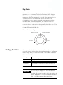
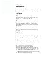
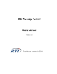
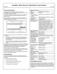
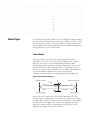
2-14
Module Operation
Input Frequency
Maximum input frequency is determined by the input configuration as
shown in the table below.
Input Configuration
Input Frequency
X4 Quadrature Encoder
250 kHz
X2 Quadrature Encoder
500 kHz
All Other Configurations
1 MHz
See Table 2.2 for additional details.
Counter Types
Each of the four possible counters can be configured to stop counting
and set a flag at its limits (linear counter) or to roll over and set a flag
at its limits (ring counter). A counter’s limits are programmed by the
CtrnMaxCount and CtrnMinCount words in the Module Configuration
Array. Both types are described below.
Linear Counter
The figure below describes linear counter operation. In linear
operation, the current count (Ctr[n].CurrentCount) value remains
between, or equal to, the user-programmed minimum count
(CtrnMinCount) and maximum count (CtrnMaxCount) values. If the
Ctr[n].CurrentCount value would go above (>) or below (<) these
values, the counter stops counting, and an overflow/underflow bit is
set. The overflow/underflow bits can be reset using the
CtrnResetCounterOverflow and CtrnResetCounterUnderflow bits.
Figure 2.6 Linear Counter Diagram
Minimum Count Value
0
Maximum Count Value
Count Up
Counter Value
Count Down
Underflow and Hold
Overflow and Hold
Pulses are not accumulated in an overflow/underflow state. The
counter begins counting again when pulses are applied in the proper
direction. For example, if you exceed the maximum by 1,000 counts,
you do not need to apply 1,000 counts in the opposite direction
before the counter begins counting down. The first pulse in the
opposite direction decrements the counter.
Module Operation
2-15
Ring Counter
Figure 2.7 demonstrates ring counter operation. In ring counter
operation, the current count (Ctr[n].CurrentCount) value changes
between user-programmable minimum count (CtrnMinCount) and
maximum count (CtrnMaxCount) values. If, when counting up, the
counter reaches the CtrnMaxCount value, it rolls over to the
CtrnMinCount value upon receiving the next count and sets the
overflow bit. If, when counting down, the counter reaches the
CtrnMinCount value, it rolls under to the CtrnMaxCount value upon
receiving the next count and sets the underflow bit. These bits can be
reset using the CtrnResetCounterOverflow and
CtrnResetCounterUnderflow bits.
Figure 2.7 Ring Counter Diagram
Maximum Count Value
Minimum Count Value
Rollover
Count Down
Modifying Count Value
Count Up
The count value (Ctr[n].CurrentCount) can be stored, reset, or preset
using the Z input, CtrReset bit in the Configuration Array, control bits
in the Output Array, or written over using a Direct Write command.
Table 2.7 Available Z Functions
Setting
For function
Store(1)
on rising edge of Z, store count in the Stored Count input word
Hold
while Z = 1, hold counter at its current value
Preset/Reset
on rising edge of Z, preset the count value to the value in the
preset word
(1) If both a store and preset function are configured, the stored count is captured before the preset operation
takes place.
IMPORTANT
Because only the Z inputs are used for external
gating and presetting, these functions are not
available for Counters 2 and 3, which do not have Z
inputs. All options are always available for Counters 0
and 1, regardless of input operational mode.
2-16
Module Operation
Counter Enable/Disable
The counter may be enabled or disabled using the CtrnEn control bit.
Be aware that disabling the counter does not inhibit any current count
loading functions (e.g. preset or direct write) or any Z function.
Z Input Functions
Store
The Z input can be used to capture the current count value even
when the counter is counting at full 1 MHz speed.
Gate
The Z inputs can be used to gate (hold) the counter at its current
value regardless of incoming A or B inputs. A gating function is
typically one that allows pulses to reach the counter (gate open) or
not (gate closed).
Z Preset
Preset can be programmed to occur based on the actions of the Z
input signal.
Inhibit and Invert
The Z input signals may be inverted and/or inhibited, depending on
the user configuration of the CtrnZInvert and CtrnZInhibit output
control bits. If the signal is inhibited, the invert bit is the Z signal for
the actions described above.
For an explanation of those bits, see Z Inv - Z Invert (CtrnZInvert) on
page 4-25 and Z Inh - Z Inhibit (CtrnZInhibit) on page 4-25.
Direct Write
You can arbitrarily change the current count value
(Ctr[n].CurrentCount) to the direct write control value
(Range12To15[n].HiLimOrDirWr). This ability applies to ranges 12
through 15. The direct write value takes effect when the Load Direct
Write bit (Range12To15[n].LoadDirectWrite) transitions from 0 to 1.
If you attempt to preset and load direct write to a counter at the same
time, only the preset (CtrnPreset) will take effect.
Module Operation
2-17
Preset/Reset
Preset sets the counter to a zero or non-zero value you define. Reset
the counter by setting this value (CtrnPreset) to zero.
Counter Reset
The CtrReset bit in the Configuration Array, when set, causes the
following to occur when the system transitions to Run or the Inhibit
Module bit transitions to 0:
• All counters are disabled and reset to zero.
• The Output Array is reset to default values until the ModConfig
bit is set (1). The default value for the Output Array is all zeros.
• The Input Array counter Status Flags (Overflow, Underflow,
RisingEdgeZ, RateValid, PresetWarning) are reset.
• The Input Array counter values (Current Count(1), StoredCount,
CurrentRate and PulseInterval) are also reset to zero.
• All counts are lost and all outputs are turned off.
IMPORTANT
For the most predictable results, you may want to
clear the output image of the processor BEFORE
performing a counter reset (CtrReset) to the 1769-HSC
module.
This is because CtrReset does not change the
processor’s output image. CtrReset sets the 1769-HSC
module’s Output Array to all zero’s. If any bit is set to
1 in the processor’s output image, when sent to the
module, it will be seen as a state transition and be
acted upon.
Soft Preset
Preset can be programmed to occur by setting the appropriate output
control bits via your control program. Setting the CtrnSoftPreset bit in
the Output Array causes the counter to be preset, changing the count
to the value in CtrnPreset.
(1) If zero is outside the MinCount and MaxCount limits set in the Configuration Array, then the Preset value is
loaded into CurrentCount instead of zero. This also causes the PresetWarning bit to be set, which, in turn, sets
the GenError bit.
2-18
Module Operation
Z Preset
Preset can be programmed to occur based on the actions of the Z
input signal.
Autopreset
If the module is configured such that CtrnMaxCount <
Ctr[n].CurrentCount or CtrnMinCount > Ctr[n].CurrentCount, then the
module will automatically change Ctr[n].CurrentCount to the
CtrnPreset value and set the CtrnPresetWarning bit.
Rate/Timer Functionality
To ensure maximum accuracy, the module offers two different
methods to calculate the rate:
• Per Pulse = 1/Pulse Interval
• Cyclic = Number of Pulses/User-Defined Time Interval
You select the method used, depending upon the pulse speed as
defined below. These are continuously available regardless of input
operational mode.
Pulse Interval Rate Calculation Method
Pulse Interval = 100 µs
Frequency = 1/100 µs = 10,000 Hz
The pulse interval rate method is very accurate for slower rates, i.e.
when the pulse interval (or time between pulses) is large compared to
the system clock timer (1 µs). A timer is used to measure the time
between two successive pulses. The inverse of this value is the pulse
interval rate. The pulse interval rate cannot be read directly from the
module. It needs to be calculated. The calculation can be performed
in the user control program.
This method is not as accurate for higher pulse rates. When the pulse
interval shrinks, two factors can distort the per pulse calculation. If the
pulse interval is close to the measuring timer’s clock frequency, 1
MHz, the granularity of the time increments has a greater effect on
rate inaccuracy. In addition, the rate may be calculated many times
over the course of a single backplane scan. As a result, the rate data