1
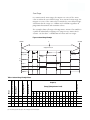
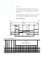
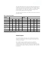
Module Operation
2-23
Cyclic Method
Since the update time is programmable, there is more flexibility in
choosing the correct fit when using the Cyclic Method.
Error estimates are shown below for a variety of update times.
Table 2.9 Maximum Cyclic Rate Errors
CyclicRate
Update
Time x
Scalar
Frequency
100 Hz
1 kHz
10 kHz
100 kHz
1 MHz
1
n/a
n/a
20.02%
2.011%
0.210%
10
n/a
20.11%
2.020%
0.210%
0.030%
100
20.01%
2.110%
0.220%
0.031%
0.012%
1000
3.010%
0.310%
0.040%
0.013%
0.010%
10,000
1.210%
0.130%
0.022%
0.011%
0.010%
See also: Rate Accuracy graph on page A-3.
Output Control
All 16 outputs can be controlled by any of the 4 counters or by the
user’s control program, via the output mask function. Output states
are determined by count, rate, ranges, mask configuration data,
overcurrent status, and safe state settings and conditions.
The 16 outputs are made up of 4 real (physical) outputs and 12 virtual
outputs. The status of the real and virtual outputs is available to the
user program. The real outputs are electronically protected from
overloads.
IMPORTANT
To turn outputs on, you must use both the Output
On Mask and the Output Off Mask.
Masks
Output On Mask
Using the Output On Mask, all of the module’s outputs can be turned
on directly by the user control program, like discrete outputs. A bit
which is set in the mask turns on the corresponding real or virtual
output.
2-24
Module Operation
Output Off Mask
The Output Off Mask has veto power over any output. It can turn any
or all of the module’s outputs off. When a bit in this mask is set to 0,
the output will be turned off. Each bit is logically ANDed with the
Output On Mask and masks of active and enabled ranges. If the bit in
this mask is set to 1, the output may be turned on or off by the ranges,
or the Output On Mask. The final result is available as the Readback.n
bit.
Ranges
Up to 16 dynamically configurable ranges are available. Ranges
activate outputs based on the current count value or the current rate
value. Each range is programmed with a type, counter number, two
limit values, an invert bit, and an output mask.
Each range is programmed with high and low limits for the chosen
value. The range’s invert bit indicates whether the range is active
between or outside the range limits. When the chosen value fulfills the
configuration parameters, the range is active as indicated in the Input
Array. When a range is active and enabled (RangeEn.n = 1), the range
turns on all outputs indicated by the Range Output Mask except those
that are prevented from being enabled by the other factors such as
Output Off Mask or Overcurrent. The status of a range is provided by
the range active status word, where 1 equals range active and zero
equals inactive.
TIP
Ranges can be disabled while the module is running
using the RangeEn.n bit in the output file. However,
even a disabled range will report when it is active or
not. For example, an unprogrammed range has limits
of 0, and points to the Ctr[0].CurrentCount value. If
this value is 0, that range is reported as active.
Module Operation
2-25
Count Range
In a non-inverted count range, the outputs are active if the count
value is within the user-defined range. In an inverted count range, the
outputs are active if the count value is outside the user-defined range.
Valid limits for the range are -2 billion and +2 billion regardless of
programmed minimum and maximum values.
The example shows all ranges referring to one counter. The module is
capable of individually assigning each range to any counter. Each
counter can also have a combination of count and rate ranges.
Figure 2.8 Count Range Example
-200,000
+106,000
0
Ctr[0].CurrentCount
Range 4
Stop Value
Range 1
Range 2
Range 4
Start Value
Range 3
on
off
Output 0
Output 1
Output 2
Output 3
Range
Range Counter Number
Range Type(1)
Range Low Limit
Range High Limit
Range Invert Bit
Table 2.10 Count Range Example Values
15
1
01
0
-7000
-5000
0
0
0
0
0
0
0
0
0
0
0
0
0
0
0
0
1
0
2
01
0
-1000
+4500
0
0
0
0
0
0
0
0
0
0
0
0
0
0
0
1
0
1
3
01
0
-4000
+3000
0
0
0
0
0
0
0
0
0
0
0
0
0
0
1
0
0
2
4
01
0
-9000
+9000
1
0
0
0
0
0
0
0
0
0
0
0
0
1
0
0
1
0 and 3
14
13
12
11
10
9
8
7
6
5
4
3
2
1
0
Outputs Affected
Outputs(2)
(Range[n].OutputControl word)
(1) For Range Type, 0 = count range and 1 = rate range.
(2) Bits 0 through 3 are real outputs. Bits 4 through 15 are virtual outputs.
2-26
Module Operation
Rate Range
In a non-inverted rate range, the outputs are active if the rate
measurement is within the user-defined range. In an inverted rate
range, the outputs are active if the rate measurement is outside the
user-defined range. The input rate can be up to 1 MHz in either
direction.
The example shows all ranges referring to one counter. The module is
capable of individually assigning each range to any counter. Each
counter can also have a combination of count and rate ranges.
Figure 2.9 Rate Range Example
-1,000,000
+1,000,000
0
Ctr[0].CurrentRate
Range 4
Range 1
Range 2
Range 4
Range 3
on
off
Output 0
Output 1
Output 2
Output 3
Range
Range Counter Number
Range Type(1)
Range Low Limit
Range High Limit
Range Invert Bit
Table 2.11 Count Range Example Values
15
1
00
1
-7000
-5000
0
0
0
0
0
0
0
0
0
0
0
0
0
0
0
0
1
0
2
00
1
-1000
+4500
0
0
0
0
0
0
0
0
0
0
0
0
0
0
0
1
0
1
3
00
1
-4000
+3000
0
0
0
0
0
0
0
0
0
0
0
0
0
0
1
0
0
2
4
00
1
-20000 +20000 1
0
0
0
0
0
0
0
0
0
0
0
0
1
0
0
1
0 and 3
14
13
12
11
10
9
8
7
6
5
4
3
2
1
0
Outputs Affected
Outputs(2)
(Range[n].OutputControl word)
(1) For Range Type, 0 = count range and 1 = rate range.
(2) Bits 0 through 3 are real outputs. Bits 4 through 15 are virtual outputs.
Module Operation
2-27
Overcurrent
If the module detects a real output point overcurrent condition, it
reports it to the input file and turns off that output. You can also
program the module to latch each of the four real outputs off,
emulating a physical fuse, or to automatically reset. The 12 virtual
outputs do not have this function.
When the OvercurrentLatchOff bit is set and an overcurrent situation
occurs, even momentarily, the associated real output is latched off
until the ResetBlownFuse bit transitions from 0 to 1.
If the OvercurrentLatchOff bit is reset and an overcurrent situation
occurs, the output turns off for 1 second and is then retried
(auto-reset). The module continues to attempt to turn the output back
on until the overcurrent situation is no longer detected and the output
is successfully turned back on.
IMPORTANT
The outputs will be on momentarily while they are
retried. The length of time they are on depends on
the magnitude of the load.
Safe State Control
The 1769-HSC module combines the Hold Last State and User-Defined
Safe State options with a safe state run alternative that allows the
module to continue to control outputs under program or fault
states(1). These options are described below.
Only the physical outputs are affected by safe state settings and
conditions. Virtual outputs, inputs, and counting are not affected by
program or fault states.
Hold Last State (HLS)
This condition applies depending on the mode of the controller.
When the hold last state option is set, the module holds the outputs at
the state they were at just before the control system transitioned from
Run to Program or Run to Fault.
HLS sets the module according to the values configured for Program
Mode (described on page 4-9) and Output Fault Mode (described on
page 4-10).
(1) The module continues to update the Input Array and count inputs in all modes. The operation of the outputs will
vary according to mode and configuration and the capabilities of the controller or bus master.
2-28
Module Operation
User-Defined Safe State (UDSS)
In this configuration, the module sets the outputs to a user-defined
safe state when the control system transitions from Run to Program or
Run to Fault.
UDSS sets the module according to the values configured for Output
Program Value (described on page 4-10) and Output Fault Value
(described on page 4-11).
Program State Run (PSR)
Program State Run allows you to specify that the output should
continue to be controlled by the module as if it were in the Run state.
That is, events on the module or changes in the Output image will
affect the physical outputs without regard to the Program_HLS or
UDSS state indicated. When this bit is set, the corresponding
OutnProgramMode and OutnProgramValue bits are ignored.
PSR sets the module according to the value configured for Output
Program State Run (described on page 4-9).
ATTENTION
!
IMPORTANT
Selecting this option will allow outputs to change
state while ladder logic is not running. You must take
care to assure that this does not pose a risk of injury
or equipment damage when selecting this option.
The prescan initiated by some controllers could have
an effect on the outputs. To overcome any changes in
physical output states that may be caused by this,
retentive output instructions (eg. latch, unlatch etc.)
should be used when bit manipulations are done on
the Output image of this module in ladder logic.
This applies to a wide range of bits when Program
State Run is selected, since presetting a counter,
enabling a range, changing a mask, and changing
Module Configuration Array settings can cause ranges
and outputs to change state.
Module Operation
2-29
Fault State Run (FSR)
Similar to Program State Run, Fault State Run allows you to specify, on
a bit basis, that the output should continue to be controlled by the
module as if it were Run state. That is, events on the module or
changes in the Output image will affect the physical outputs without
regard to the Program_HLS or UDSS state indicated. When this bit is
set, the corresponding Program Mode and Program Value bits are
ignored.
FSR sets the module according to the value configured for Output
Fault State Run (described on page 4-10).
ATTENTION
!
IMPORTANT
Selecting this option will allow outputs to change
state while ladder logic is not running. You must take
care to assure that this does not pose a risk of injury
or equipment damage when selecting this option.
The prescan initiated by some controllers could have
an effect on the outputs. To overcome any changes in
physical output states that may be caused by this,
retentive output instructions (eg. latch, unlatch etc.)
should be used when bit manipulations are done on
the Output image of this module in ladder logic.
This applies to a wide range of bits when Fault State
Run is selected, since presetting a counter, enabling a
range, changing a mask, and changing Configuration
Array settings can cause ranges and outputs to
change state.
Program to Fault Enable (PFE)
The ProgToFaultEn bit allows you to select which data value (Program
Value or Fault Value) to apply to the output when the Output State
Logic state Prog_HLS changes to indicate Fault_HLS.
If PFE is 0, the module leaves the Program value applied. If PFE is set
to 1, the Fault value is applied.
2-30
Module Operation
TIP
If the module is in a safe state such as Program or
Fault which is configured to turn an output ON and
excessive current is drawn from the output, the
output will still turn off according to the
programmed OverCurrentLatchOff bit configuration.
The module’ s Default Safe State configuration is all zero’s, resulting in
the following:
• Program State = UDSS
• Program Value = OFF
• Program State Run = No
• Fault State = UDSS
• Fault Value = OFF
• Fault State Run = No
• PFE = leave program value applied.
Output Control Example
The following example illustrates the module’s output control flow.
The following conditions are reflected in Table 2.12:
• Range 0 is enabled and active
• Range 1 is disabled
• Range 2 is enabled but not active
• an overcurrent condition exists on real output 3
• OvercurrentLatchOff is set
• the system is in Run mode
Module Operation
2-31
The table below illustrates the step-by-step logical operations that are
performed to determine the final output state. For example, Range 1
values do not affect the output because Range 1 is disabled, and the
Output Off Mask causes some of the outputs to change to zero
because it takes priority over the range masks.
The output parameters shown in the table have been discussed in the
previous sections.
Table 2.12 Output Control Example
Output
Parameter
Mask Information
Logical
Operation
Range 0
0 0 0 1 0 1 1 0 1 1 0 1 0 0 0 1 OR
0 0 0 1 0 1 1 0 1 1 0 1 0 0 0 1
Range 1
0 0 1 0 1 1 1 1 1 1 1 1 0 0 1 0 OR
0 0 0 1 0 1 1 0 1 1 0 1 0 0 0 1
Range 2
0 1 0 0 0 0 0 0 0 0 0 0 1 1 0 0 OR
0 0 0 1 0 1 1 0 1 1 0 1 0 0 0 1
Output On Mask
0 1 0 0 1 0 1 0 1 0 1 0 1 0 0 0 OR
0 1 0 1 1 1 1 0 1 1 1 1 1 0 0 1
Output
Overcurrent
- - - - - - - - - - - - 1 0 0 0 AND
0 1 0 1 1 1 1 0 1 1 1 1 0 0 0 1
Output Off Mask
1 1 1 1 0 0 0 0 1 1 1 1 1 1 0 0 AND
0 1 0 1 0 0 0 0 1 1 1 1 0 0 0 0
Program State
Values
- - - - - - - - - - - - 1 1 1 1 Override
0 1 0 1 0 0 0 0 1 1 1 1 0 0 0 0
Fault State Values - - - - - - - - - - - - 1 1 1 1 Override
0 1 0 1 0 0 0 0 1 1 1 1 0 0 0 0
Final Output State
0 1 0 1 0 0 0 0 1 1 1 1 0 0 0 0
Result(1)
(1) Bolded text indicates that these values have changed.
Readback/Loopback
The Readback/loopback function is the feedback of the module’s
outputs via its Input Array. This 16-bit image includes both real (4)
and virtual (12) outputs.
If the module’s output is OFF due to overcurrent, both the
Overcurrent status flag and the Readback bit will indicate the
condition being 1 and 0 respectively. Conversely, should the output
be ON due to any module control (eg. UDSS), this will be indicated
by Readback.