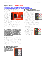
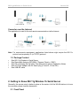
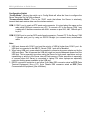
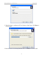
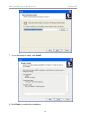
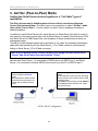
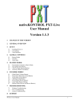
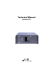
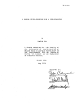
1
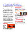
ATC-2002WF
802.11gb Wireless LAN to
Dual-Port RS232 Serial Server
802.11gb Wireless to Serial Server
Version20060502
Quick Start 1 - READ THIS!
Things You Need to Know That are Not Obvious:
This section explains what the Switch, LEDs, etc. do.
4b “System” LED indicator:
4b1
If System LED is OFF then the
Serial Device is initializing or other task
and is NOT monitoring
Wireless LAN activity.
4b2
If System LED is
Flashing, the Serial
Device is in “Set Up Mode”
and the “Config. Switch” at
the rear of the device is in
the “UP” “Config” position”
and is NOT monitoring Wireless LAN
activity.
4b3
If System LED is solidly Yellow
color, the Serial device has initialized and
is monitoring Wireless LAN activity.
1 “Configuration” switch: The
slide switch located on the rear of the
Serial Server
must be
switched “up”
to the “Config.
Mode” to use
the Set Up
Utility. This
switch is used
to enable the
Configuration process irrespective of
whether the configuration is done with
USB, the COM ports or over-the-air.
Likewise to “Run” the Serial device, the
switch must be set downward to the
“Communications Mode” position.
4c WLAN LED:
As wireless LAN activity
is passing either to or
from the Serial Device,
the Green WLAN LED
will briefly flash to
indicate wireless data
activity during each
burst of data transfer.
2 “USB Port”: The USB port is used
only for configuration, and when the USB
cable is plugged in it will borrow the
RS232 signals from the COM1 port. So
when configuration is completed, the
USB cable MUST be removed for COM1
to function properly.
3
“Power” It is recommended to also
use the power supply when configuring
the Serial Device instead of relying solely
on the USB cable to provide power.
Laptops in particular are stingy with
restricting power available from the Laptop
USB port.
4
What the LEDs indicate:
4a. When you apply Power…:
The two Td RS232
output LEDs Turn ON
immediately displaying
Red.
2
More Quick Start 2 - READ THIS TOO!
More Things You Need to Know That are Not Obvious:
This section explains the basics of Starting Configuration.
So it is very important when
To configure the Serial Device:
1 Load the Set UP Utility from the CD, It
should auto-install upon inserting CD to a
PC.
2 Plug in the Power Supply into the
Power Jack. (You may not need the power
supply to configure the Serial Device since there
may be enough power available from the USB port
to power the Serial Device. Laptops may limit the
power available at the USB so a power supply may
be necessary.)
3 Plug in the USB cable into the Serial
Device and PC. The computer should
audibly chime to indicate a USB device has
been plugged in. If it does not automatically
associate the new USB Serial Device with
the Set UP Utility then use the Browse
function to direct the USB Set Up to the CD
drive to locate the Drivers and Set Up
Utility for the Serial Device. (Note: You may
also use the PC Serial Ports to configure or
it can Configure over-the-air with a radio
link.)
4 Flip the Switch on the rear panel UP to
“Config. Mode.”
IMPORTANT NOTE:
When you are
configuring the
Serial Device,
flipping the
switch to
Config Mode
will take the
RS232 signals away from COM1 port,
since the USB borrows the COM 1
channel temporarily for Configuration.
Configuration is complete to flip this
switch back down to the
“Communications Mode” to run.
When in Configuration Mode, the Amber
(yellow) color “SYSTEM” LED with flash
to indicate that this is Configuration
mode. You MUST wait until this LED
begins to flash to read or alter the
configuration
settings.
5 When finished
with Configuration,
the flashing
Yellow System LED warns you to flip the
Configuration switch DOWN to the
“Communications (RUN) Mode” and the
System LED will then remain solidly
illuminated.
6 Remove the USB cable used to set
up the Serial Server. COM 1 will not
function properly as an RS232 port with
the USB cable also plugged in.
Remember that the USB cable borrows the
COM 1 port for configuration, so the USB
cable must be removed to restore COM1 to
RS232 activity.
The information in this guide may change without notice. The manufacturer assumes no
responsibility for any errors, which may appear in this guide.
Ethernet is a trademark of XEROX Corporation. Microsoft, Windows and Windows logo are
trademarks of Microsoft Corporation.
It should be declared that this 802.11g wireless to Serial Server is limited in CH1~CH11 by
specified firmware controlled in USA.
Copyright 2005. All right reserved. No Part of the contents of this guide maybe transmitted or
reproduced in any form or by any means without the written permission of the manufacturer.
Printed in Taiwan.
FCC Statement
This equipment has been tested and found to comply with the limits for a class B digital
device, pursuant to part 15 of the FCC Rules. These limits are designed to provide
reasonable protection against harmful interference in a residential installation.
This equipment generates, uses and can radiate radio frequency energy and, if not installed
and used in accordance with the instructions, may cause harmful interference to radio
communications. However, there is no guarantee that interference will not occur in a
particular installation. If this equipment does cause harmful interference to radio or television
reception, which can be determined by turning the equipment off and on, the user is
encouraged to try to correct the interference by one or more of the following measures:
--- Reorient or relocate the receiving antenna.
--- Increase the separation between the equipment and receiver.
--- Connect the equipment into an outlet on a circuit different from that to which the receiver is
connected.
--- Consult the dealer or an experienced radio/TV technician for help.
This device complies with Part 15 of the FCC Rules. Operation is subject to the following two
conditions:
(1) This device may not cause harmful interference, and
(2) This device must accept any interference received, including interference that may cause
undesired operation.
FCC Radiation Exposure Statement:
This equipment complies with FCC radiation exposure limits set forth for an uncontrolled
environment. This equipment should be installed and operated with minimum distance 20cm
between the radiator & your body.
This transmitter must not be co-located or operating in conjunction with any other antenna or
transmitter.
To maintain compliance with FCC RF exposure compliance requirements, please avoid direct
contact to the transmitting antenna during transmitting.
INFORMATION TO USER:
The User Manual or Instruction Manual for an intentional or unintentional radiator shall
caution the user that changes or modifications not expressly approved by the party
802.11gb Wireless to Serial Server
Version1.00
responsible for compliance could void the user’s authority to operate the equipment.
CAUTION: Any changes or modifications not expressly approved by the party responsible for
compliance could void the user’s authority to operate the equipment.
Prohibition of co-location
This device and its antenna(s) must not be co-located or operating in conjunction with any
other antenna or transmitter.
MPE Statement (Safety Information)
Your device contains a low power transmitter. When device is transmitted it sends out Radio
Frequency (RF) signal.
CE Mark Warning
This is a Class A product. In a domestic environment, this product may cause radio
interference in which rack the user may be required to take adequate measures.
5
802.11gb Wireless to Serial Server
Version1.00
1. Introduction
The RS232 connection application has used for a long time. RS232 cable has limitations in
distance. WLAN (Wireless Local Area Network) has become a worldwide standard protocol
for wireless applications. There are many applications for using RS232 connection over
WLAN, including POS, data capture, telemetry, PLC controllers, remote control, vending
machine, industrial control, and others. The device that supports connection over WLAN is
called as Wireless to Serial Server.
Throughout the guide, the 802.11g Wireless to Serial Server will be referred as the
“Server”.
1.1 802.11g Wireless to Serial Server Application
Peer to Peer
The host PC and an RS232 device communicate with each other via the individual converter.
The access point is optional.
Converter to PC WLAN
The RS232 device is connected to the converter, and the PC is equipped with the wireless
card. Two sides communicate through the converter and wireless card. The access point is
optional.
Converter to Access Point
The RS232 device is connected to the converter, the host PC is connected to the access
point via LAN.
6
802.11gb Wireless to Serial Server
Version1.00
Converter over the Internet
The application is used for far end remote communication via the Internet.
Note: For environments requirement, applications listed above might require the 802.11x
protocol and proprietary IP (or TCP/IP) protocol.
1.2 Package Content
Ÿ
Ÿ
Ÿ
Ÿ
Ÿ
One 802.11g Wireless to Serial Server
One Removable Antenna (RP-SMA) (“Reverse Polarity – SMA”)
One CD (containing Set Up Utility, User Manual and various Application Notes)
One AC Power Adapter with DC barrel plug (2.1mm ID, 5.5mm OD)
One USB MF cable
2. Getting to Know 802.11g Wireless To Serial Server
Generally, the access point is better to place at the center of all the WLAN stations, to know
the converter, please read the description.
2.1 Front Panel
7
802.11gb Wireless to Serial Server
Version1.00
LED Indication
WLAN Blinks green to indicate data is transmitting and receiving.
SYSTEM Off to indicate system is in initial status and the converter not ready to operate.
Lights yellow to indicate system is in communication mode.
Blinks to indicate system is in configuration mode.
TD Lights red to indicate the converter is power on.
Blinks green to indicate the converter is transferring data to RS232 device.
RD Lights red to indicate the cable is connected.
Blinks green to indicate the converter is receiving data from RS232 device.
CTS Blinks green to indicate the converter is transmitting CTS signal.
Note: TD, RD, and CTS LED are explained for COM 1 and COM 2 port.
Port Definition
USB Port Plug in the USB (B-type female) into the USB port.
RESET Press reset bottom at once to reset the system. Press reset bottom for 5 seconds to
reset to default setting.
2.2 Rear Panel
POWER Plug in the power adapter of 12V DC/1A into the power port.
8
802.11gb Wireless to Serial Server
Version1.00
Configuration Switch
“Config Mode”: Moving the switch up to Config Mode will allow the User to configure the
Server using the Set Up Utility software.
“Communication Mode”: This is the “RUN” mode that allows the Server to wirelessly
transmit data and receive data over the wireless network.
COM 1 COM 1 port is used as DTE mode male connector. It is wired about the same as the
male serial COM port connector on a PC. To connect a PC to the Server COM 1 use
a cable with 2 female connectors with NULL crosses on pins 2&3, 4&6, 7&8 with pin 5
to pin 5.
COM 2 COM 2 port is used as DCE mode female connector. Connect PC To the Server COM
2 (female port) port by using an RS232 Straight (no crossed wires) male/female
cable.
Note:
1. USB port shares with COM 1 port and the priority of USB is higher than COM 1 port. As
USB port is connected to the NB/PC, Server COM 1 port will be disabled.
2. When using USB port, power should be supplied to converter by power adapter not by the
USB port alone. This is because the USB port might not receive adequate power from the
USB port. This is especially true when using the Server for high power operations such as
transmitting or writing to the Server internal Flash memory. Power starvation is especially
of concern when the Server is connected to laptop PCs since laptops are especially
restrictive limiting power available to the USB port.
3. RS232 connection restriction is as follow. 9-pin Male DE9 connector wired as DTE (Data
Terminal Equipment) (like a PC). 9-pin Female DE9 connector wired as DCE (Data
Communication Equipment) (like a Modem).
9
802.11gb Wireless to Serial Server
Version1.00
3. Installation
To start the installation, please follow the steps.
1. Insert the CD into the CD-ROM.
2. Select the setup file: setup.exe. Click “setup” to run the program. The following dialogue
will appear. Click “Yes” to continue.
3. As entering the welcome screen, click “Next” to continue.
4. Enter the User Name and Organization.
10
802.11gb Wireless to Serial Server
Version1.00
5. Select the folder for installing the 802.11g Wireless to Serial Server. Click Browse to
choose the path.
6. Select the shortcut in the following Start Menu folder. Click Browse to choose the path.
11
802.11gb Wireless to Serial Server
Version1.00
7. If you are ready to install, click Install.
8. Click Finish to confirm the installation.
12
802.11gb Wireless to Serial Server
Version1.00
13
802.11gb Wireless to Serial Server
Version1.00
4. Configuration
To configure the converter, as the System LED starts to blink, than go to
Startà Programà 802.11g Wireless to Serial Serverà WlanSerialSetup.
1. Select the configuration mode from: USB configuration, RS232 configuration, and TCP/IP
configuration. Click Load Config to enter the configuration mode.
Note: Below is example for RS232 configuration only.
2. Before load the configuration, select the PC COM port first. Note that it is required to
select the COM port of PC. Click OK, configuration will be loaded automatically.
3. Network section enables user to change the IP Address, IP Mask, and Gateway. To use
14
802.11gb Wireless to Serial Server
Version1.00
DHCP, pleas click “Enable”.
4. Wireless section enables user select the operation mode, channel, SSID, TX rate, and
Encryption mode. To set the further WEP, enable the encryption function, and set the key.
15
802.11gb Wireless to Serial Server
Ÿ
Ÿ
Ÿ
Ÿ
Ÿ
Version1.00
Operation Mode: To select infrastructure or Ad-Hoc mode.
Channel: As in Ad-Hoc mode, user can set the channel to match with another side
station.
SSID: User can set the SSID to match with the AP(Infrastructure mode) or
station(Ad-Hoc mode).
TX Rate: User can set the TX rate to fit with the operation environment.
Encryption Mode: User can set the encryption mode to set the encryption function.
5. RS232 Port 1 section enables user to set the Baud Rate, Parity, Data Bits, Stop Bits, Flow
Control, Local TCP Port, Remote IP, Remote TCP Port, Idle Time, and Port 1 Mode.
Note: For Port 1 being setting as Client mode, the program of remote server should be ready
for connection (listening at IP listed in “Remote IP” and TCP port listed in “Remote TCP
Port”).
16
802.11gb Wireless to Serial Server
Version1.00
6. RS232 Port 2 section enables user to set the Baud Rate, Parity, Data Bits, Stop Bits, Flow
Control, Local TCP Port, Remote IP, Remote TCP Port, Idle Time, and Port 2 Mode.
Note: The Port 2 setting is the same as Port 1.
17
802.11gb Wireless to Serial Server
Version1.00
18
802.11gb Wireless to Serial Server
Version1.00
Site Survey section enable user to survey the AP site. Click Refresh to survey.
19
802.11gb Wireless to Serial Server
Version1.00
Profile section enables user to set and save the profile for different connection settings. User
can import and export the profile to another Server.
20
802.11gb Wireless to Serial Server
Version1.00
Information section enables user to upgrade the firmware. It is strongly recommended to
download the Firmware via the TCP/IP connection for fastest download.
21
802.11gb Wireless to Serial Server
Version1.00
5. Ad Hoc (Peer-to-Peer) Mode
Linking two Serial Server devices together in a “Cut Cable” type of
application.
Two Peer devices may be linked together to form a direct connection without an
Access Point between them. This direct one-to-one connection is called “Ad Hoc” mode
(also called “Peer-to-Peer”). It is also called ‘cut cable” since it wirelessly simulates a
cabled installation.
In addition to paired Serial Server links (serial Server–to–Serial Server) the Ad Hoc mode is
also used for other peer-to-peer links such as Serial Server-to-Laptop, Serial Server-to-PDA,
and Serial Server-to-USB Dongle links, and examples of these connections are shown on
subsequent pages.
This Ad Hoc mode example shown below simulates a “cut cable” by wirelessly eliminating a
cable with data transferring to/from Serial Server_1 Port 1Male connector and wirelessly
linking to Serial Server_2 Port 2 Male connector.
Hint: A key to getting Ad Hoc to work properly is to assign one Peer device set as
“Server” and set the other Peer device set as “Client.”
Assume that Serial Server_1 is connected to RS232 device via RS232 port 1 and Serial
Server_2 is connected to another RS232 device such as a Host PC via RS232 port 2.
Serial Server_2 will be configured as Client
mode.
When switched to Ad Hoc mode, the Serial
Server will send out a beacon with its SSID
(network) name.
The Client device will given the IP address
of the Server Device and thus will “target”
the Server device.
For this example Serial Server_1
will be configured as Server
mode.
When switched to Ad Hoc mode,
the Serial Server will send out a
beacon with its SSID (network)
name.
22
802.11gb Wireless to Serial Server
Version1.00
The following procedures can be used to set up the Ad Hoc (Peer-to-Peer) mode for two
Serial Server Devices. The examples are real values that will result in a functioning set up.
There is space provided for you to enter in your own choice of values in a printout.
The two Serial Server devices Set Up screens are shown side-by-side so the settings
relationship of the two devices can be better understood.
Server Device:
Client
Device:
This device will be configured as
“Server”. The “Server” device will wait
to be contacted by a “Server” device
that sends out a beacon.
This device will be configured as
“Client”. The Client device will send
out a beacon to try to connect to the
“Server” device.
1a) Configure Serial Server_1
“Net” Tab window as follows:
1b) Configure Serial Server_2
“Net” Tab window as follows:
The IP Address of this device is set to
192.168.1.253 (for example). Make sure no other
device uses this IP address. If another device
already uses 192.168.1.253, then change to
another appropriate IP address.
(Notice the address for Serial Server_1 and Serial
Server_2 (in the right hand column) are different.)
The IP Address of this device is set to
192.168.1.254 (for example). Make sure no other
device uses this IP address. If another device
already uses 192.168.1.254, then change to
another appropriate IP address.
(Notice the address for Serial Server_1 (in the left
hand column) and Serial Server_2 are different.)
“Server” Device “Net” Tab Set Up
“Client” Device “Net” Tab Set Up
With a Subnet Mask of “255.255.255.0”, the IP addresses should be the same up to the last decimal (dot).
The last value can be any number between 0 and 255 that has not already been allocated.
My “Server” IP address is:
My “Client” IP address is:
(you can write your “Server” Device IP address here).
(you can write your “Client” IP address here).
______ . ______ . ______ . _______
______ . ______ . ______ . _______
23
802.11gb Wireless to Serial Server
Version1.00
Server Device:
2.
Client Device:
Configure both Serial Server_1 and Serial Server_2 “Wireless” tab windows as follows:
2a. The Operation Mode is set to Ad hoc (instead of Infrastructure). This is a key to Peer-to-Peer
operation, in that both Peer devices must be in “Ad Hoc” mode. This is also true if the second Peer device
is not another Serial Server device, but might be a Laptop, PDA, USB Dongle or any other Peer Device.
Note that both devices have the “Wireless” tab settings set exactly the same for both
“Server” and “Client” devices.
Serial Server_1 “Wireless” Tab
Serial Server_2 “Wireless” Tab
2b. Channel: Select a WLAN Channel that is not locally used by other local devices, e.g. Channel 1 in this
example. Hint: BOTH devices MUST be set exactly to the same channel. (This is not like Infrastructure
mode where the channel selection does not matter because in Infrastructure (Network mode) the Serial Server
Device jumps to the channel of the strongest Access Point with the same SSID.) But in Ad Hoc mode, the two
devices are being paired and locked together including exactly matching the channel settings.
You can check for channel usage in your location by using the “Site Survey” tab.
My Channel setting is channel ___________ (Hint: channels 1, 6, 11 are non-overlapping).
2c. SSID: Assign the same SSID (Network Name) to each device, for example “WLAN_RS232”.
You can use another channel or SSID name as you like, but both Serial Server_1 and Serial Server_2 must
have the same exact SSID as well as the same channel.
My SSID (network name) is _________________________________________________________
2d. Encryption: If Encryption is set to “Disable”, then WLAN WEP/WPA encryption function is not activated.
But if Encryption is activated by setting to WEP or WPA, then both Serial Server “Server” and Serial Server
“Client” must be set to the exact same values for Encryption, WEP Key Use, and Key values. (Note that it is
easier to get the devices working together WITHOUT any encryption enabled, because it is a significant item
that can be easily miss-set. You can always enable WEP or WPA security after the Peer-to-Peer is set up and is
operating correctly.) WEP and WPA key values are “hexadecimal” which is 0-9 and A, B, C, D, E, F.
My Encryption Key is:
( ) WEP-64 __ __ __ __ __ __ __ __ __ __ (10 characters)
( ) WEP-128 __ __ __ __ __ __ __ __ __ __ __ __ __ __ __ __ __ __ __ __ __ __ __ (23 characters)
( ) WPA – TKIP ______________________________________________
( ) WPA – AES ______________________________________________
24
802.11gb Wireless to Serial Server
3)
Version1.00
Setting RS232 Serial Port settings for Ad Hoc
Remember that in this example we are eliminating a cable assembly with data transferring to/from Serial
Server_1 Port 1Male connector and wirelessly linking to Serial Server_2 Port 1 Male connector. The key to Ad
Hoc is have one Peer device set as “Server” and the other Peer device set as “Client.” Thus the “Client”
device points-to (targets) the “Server” device. The same configuration philosophy of settings for this Port1
also applies to the second Port2.
Serial Server “Server” RS232 Port1
Serial Server “Client” RS232 Port1
3b) Configure Serial Server_2 RS232 Port 1 (Male
connector) with the Mode set to “Client” (see red
circled near bottom of the window) (Serial Server_1
RS232 Port 1 was set as “Server”). Note that when
you set this device to “Client” the grayed-out
Remote Port and Remote IP became active. Set
the Remote Port of Serial Server_2 to match the
“Local Port” setting for the target TCP port on Serial
Server_1 (2001) as seen on the left column.
Remember that the IP address assigned to Serial
Server_1 was 192.168.1.253, so enter that address
into the Remote IP field of Serial Server_2.
3a) Configure Serial Server_1 RS232 Port 1 (Male
connector) with mode set to “Server” (Serial
Server_2 RS232 port 1 will be set as “Client” in the
right hand column).
The “grayed-out” Remote IP and Remote Port
are not used when the device is set as “Server.”
(Remember that the IP address set for this device
was “192.168.1.253” which will be entered into
Serial Server_2 “Remote IP” (as shown in the right
hand column.)
See settings below, how a “Client” device
“Targets” the “Server” device.
Remember this device IP Address is
192.168.1.254
It is set as “Client”.
Remember this device IP Address is
192.168.1.253
It is set as “Server”.
The IP network address I chose for the “Server” device was ___ . ___ . ___ . ___ , so that is
the IP address that needs to be loaded into the “Remote IP” field of the “Client” device.
There are 2 ports on the Serial Server, and you need to tell this Client device to which port on
the “Server” to point. The TCP port of the Server device I want the Client device to point to is
_______ (hint: use 4 or 5 digit number (greater than 2000).
25
802.11gb Wireless to Serial Server
Version1.00
The Client device has now been configured to point to the Server device.
The fastest linkage will be if the Server device is already powered up when the Client device
is power up, but linkage will occur in any event.
26
6. Ad Hoc connection: Laptop to Serial Server Device
This application note is specifically created for Dell Laptop computers but it is similar to all
Laptop devices running XP with SP2.
Setting up a Serial Server device for Ad Hoc (Peer-to-Peer) to a
Wireless Laptop/Notebook PC.
1. In the Set Up Utility of the Serial Server device, select the Wireless tab.
2. Select Ad Hoc as the Operation Mode. (Ad Hoc is for Peer-to-Peer mode.)
Note: this will cause the Serial Server to send out beacons to broadcast the SSID network name you
chose. Any laptop that does a survey of available wireless networks to link to should be able to read
this beacon and display the Network Name in order for you to link to it.
3. Enter the SSID network name you chose to be broadcast. For this illustration, the name
WLAN_RS232_AdHoc is entered.
4. Encryption Mode: If you have XP OS with SP2 installed on your laptop, you will need to enable
a security encryption mode and enter a key value. The simplest is to use the WEP-64 key. XP-SP2
will force you to use a security encryption key. If you have XP-SP2 you do not have a choice, you must
enter an encryption key.
NOTE: The WEP network key must be either exactly 10 characters long (WEP-64) or exactly 26 characters
long (WEP-128) using the hexadecimal numbers 0-9 and the letters a-f (A-F) (letters can be uppercase or
lowercase).
5.
Save your settings with the Save button on the Utility.
My IP address is:
(Located on “Network” tab.)
(You can write your Device IP address here).
______ . ______ . ______ . _______
My Channel setting is channel _____
(Hint: channels 1, 6, 11 are non-overlapping).
My SSID (network name) is:
____________________________________
My Encryption Key is:
( ) WEP-64 (10 characters)
__ __ __ __ __ __ __ __ __ __
(
) WEP-128 (23 characters)
__ __ __ __ __ __ __ __ __ __ __ __
__ __ __ __ __ __ __ __ __ __ __
(
) WPA – TKIP
_____________________________________
(
) WPA – AES
_____________________________________
802.11gb Wireless to Serial Server
Version1.01
Setting up a Laptop/Notebook PC for Ad Hoc (Peer-to-Peer) to a
Wireless Serial Server device.
1
On your Laptop or Notebook computer, click on the Wireless Networks icon in the system tray in
the lower right of the XP laptop screen.
2
Click on View Available Networks.
3. Find the Serial Server network name you created during set up of the Serial Device. Notice that
since the Serial Server was set to Ad Hoc mode, it sends out a beacon with its network name (in this
case “WLAN_RS232_AdHoc”) the network name will appear in a list of available wireless networks
when you “Refresh network list”.
4
Tap the Connect button at the lower right to link the laptop to the selected Serial Server network.
Follow the prompts to complete Ad Hoc connection to the Serial Server.
5
If you do not see the Serial Server network name you assigned to the Serial Server, you may
need to proceed on to the section immediately following this entitled Creating an Ad Hoc Network
from a Laptop/Notebook PC to another Peer Device. Then return to this section to complete
connection to the Serial Server device Ad Hoc network.
28
802.11gb Wireless to Serial Server
Version1.01
Creating an Ad Hoc Network from a Laptop/Notebook PC to another Peer
Device.
If you can not simply link to the Ad Hoc network name when searching for available wireless networks,
it may be because your laptop is not set up to allow connection to Ad Hoc networks.
So proceed as follows.
On the Laptop/Notebook PC
1
Open Network Connections in Control Panel.
2. Right-click Wireless Network Connection, and then click Properties.
3
On the Wireless Networks tab, verify that the Use Windows to configure my wireless
network settings check box is selected. If it is not, click to select the check box.
4
Click Add.
5
Type the network name in the Network name (SSID) box.
6
Select the This is a computer-to-computer (ad hoc) network; wireless access points are
not used check box.
7
Click Open in the Network Authentication list.
8
To create an ad hoc network with no security settings, click Disabled in the Data encryption list.
29
802.11gb Wireless to Serial Server
Version1.01
–or–
To create an ad hoc network that has WEP encryption, clear the The key is provided for me
automatically check box, click WEP in the Data encryption list, and then type the network key in the
Network key box and again in the Confirm network key box.
NOTE: The network key must be either exactly 10 characters long (WEP-64) or exactly 26
characters long (WEP-128) using the hexadecimal numbers 0-9 and the letters a-f (A-F) (letters
can be uppercase or lowercase).
9
Click OK.
10
On the Wireless Networks tab, click OK.
30
802.11gb Wireless to Serial Server
Version1.01
Choosing Which Types of Networks to Access
1. Open Network Connections in Control Panel.
2. Right-click Wireless Network Connection, and then click Properties.
3. On the Wireless Networks tab, click Advanced.
4. Under Networks to access, click the option you prefer. For Ad Hoc network you must either
choose either:
Any available network (access point preferred) or
Computer-to-computer (ad hoc) network only.
and then click Close.
5
On the Wireless Networks tab, click OK.
References:
http://support.dell.com/support/edocs/network/p70008/EN/xpbasic.htm#toc_15
End of section.
31
802.11gb Wireless to Serial Server
Version1.01
7. Upgrading Firmware
7.0 Are you Registered to receive emailed Notification of Updates? As a purchaser of
the Server device, you are entitled to receive email notice of any upgrades and
enhancements. If you have not registered onto the Product Registration List to be
automatically notified of Firmware upgrades and feature enhancements, you may register at
the factory web site listed on the Contacts page of this user manual.
7.1 Setting up to Upgrade Firmware
7.1.1
Plug in Power Supply to Power Jack
It is especially important that the Server receive adequate power during this sensitive
Firmware Upgrade Procedure. A laptop PC in particular may be especially frugal in
restricting the amount of power that can be extracted from the USB port, and the Server may
be power-starved. So always use a power supply when upgrading firmware.
7.1.2
Set the “Config./Communications switch UP
to the Configuration Mode.
7.13
Firmware can be upgraded using over-the-air TCP/IP (the fastest method) or
either RS232 port (slower) as described in the following sections (upgrade via USB port
is forbidden since it is so slow). But please read important Sections 4.2 and 4.3 first.
For over-the-air TCP/IP Firmware upgrade – see Section 4.4
For RS232 Firmware upgrade – see Section 4.5
32
802.11gb Wireless to Serial Server
Version1.01
7.2 How to Read the Current Firmware and Set Up Utility Software Versions
From the Information Tab:
Read the current Set Up Utility program version in the “Utility Version” box.
Read the current Firmware revision level of the Server in “Firmware Version” box. Firmware
is the software that drives the Server and determines the operating characteristics of the
Server.
If newer Firmware Version is available, the Firmware can be loaded into the Server from this
Information tab section of the Set Up Utility.
7.3 Loading New Firmware
Cautionary Note: The Firmware files are VERY LARGE FILES, and if the method you select
of transferring the data into the Server is slow then it can take a long time to load and store
the file into Flash Memory.
The Preferred Method of Loading Firmware: If your installation is able to load the new
Firmware using the fastest method available (“over-the-air TCP/IP”) it will take considerably
less time than using a serial port or the USB port. If it is necessary to use a Serial Port or USB
port it can take 10 minutes or so to load the firmware by these slower methods.
Since the over-the-air TCP/IP method of firmware upgrade is the fastest and preferred
method, it is illustrated first.
7.4 Fastest Method: Loading New Firmware using TCP/IP “over-the-air”
For this procedure of loading Firmware over-the-air, you must be able to connect
over-the-air with the Server. Thus all of the normal wireless network connection process
must be functioning, including that the PC you are running the Set Up Utility must have a
connection to the wireless network and the settings for the RS232 Serial Server must match
the network settings.
33
802.11gb Wireless to Serial Server
Version1.01
A quick Ping test: Can the Server device “Ping” from the PC that is running the Set Up Utility?
If the Server can not be pinged then certainly there is not a connection made to upload new
firmware to the Server via over-the-air TCP/IP. (See Section XX.X “How to Ping Test”.)
Presuming that there is a successful wireless network connection between the PC running
the Set Up Utility and the Server device to receive the Firmware upgrade, continue by reading
the Server settings wirelessly using the over-the-air TCP/IP method.
From the Configuration Method options select the method TCP/IP Configuration.
Enter the IP Address you have assigned to the Server.
In this example, the Factory Default IP
address is shown.
Tap the “OK” button to accept the IP settings and allow the Set UP Utility to attempt to connect
with the Server.
34
802.11gb Wireless to Serial Server
Version1.01
Result 1: Wireless Connection Successful
If the wireless link connection is successful, then the Utility
will open with the display of the Network settings read from
the Server.
Jump down “Loading Firmware into the Server”
Result 2: Wireless Connection NOT Successful
If the wireless link connection is NOT successful, then the
Utility will display the error message that it can’t connect to
the Server.
Please refer to the Section XX Trouble Shooting:
Problems with making a wireless connection to the
Server. If the wireless connection to the Server still cannot be made, consideration should
be given to loading the new Firmware via the slower RS232 or slower USB interface by using
the instructions in the following sections:
Loading New Firmware using Either RS232 Port on the Server
Presuming there is now a confirmed wireless network connection between the PC running the
Set Up Utility and the Server device, continue by now loading the new Firmware.
Loading Firmware into the Server
Use the Browser button to
locate the Firmware file where
it has been stored on the PC.
The file will typically have a
name similar to “run.bix.fw”.
Once the Firmware has been
located and applied into the
Browser bar, the Firmware
download can be started by
tapping the Download button.
35
802.11gb Wireless to Serial Server
Version1.01
WARNING! Once the download activity has been
started, do not disrupt download activity for any
reason.
Download using over-the-air TCPIP make take 1 to 2 minutes as the Progress bar indicates
the Firmware download
progresses.
When the Firmware download is
completed, the Firmware
Transmission Done message will
display.
This should complete the Firmware upgrade. At this time
the Configuration Switch on the rear of the Server can be
switched down to the Run position to resume operation
as a Serial Server Device.
Press the “Reset” button for 5 seconds!
After uploading new Firmware in the Serial Server the Reset
button on the Front MUST pressed for 5 seconds for the new
firmware to take effect. This is VERY IMPORTANT. Do not
ignore this step.
The Serial Server will revert to Factory Default Settings, so the
fields must be entered again for such things as IP Address, SSID,
Security Key and so on.
36
802.11gb Wireless to Serial Server
Version1.01
7.5 Loading New Firmware using Either RS232 Port on the Server
For this procedure of loading Firmware via either RS232 Port you must connect an RS232
cable from a PC that has the Set Up Utility loaded and connect to either DE9 port
(a.k.a. DB9) on the Server.
Either Server RS232 port can be used. However there are differences.
If Server COM Port 2 (DE9-Female) is selected for loading Firmware then a common
D9Male-to-D9Female “straight cable” can be used (straight means pin 2 goes to pin 2, pin 3
goes to pin 3, etc.).
If Server COM Port 1 (DE9-Male) is selected for loading Firmware then a NULL Cross cable
must be used: D9Female-to-D9Female Null Cross cable (Null cross means pins 2 and 3
cross (pin 2 goes to pin 3, pin 3 goes to pin 2), pins 4 & 6 cross, pins 7 & 8 cross, pin 5 goes
to pin 5 (Ground)).
From the Configuration Method options select the method RS232 Configuration.
The available PC COM ports will be displayed by tapping the Drop Down arrow from the
“Select PC COM Port:” field. Note that this is the PC COM Port number and this PC COM Port
number has nothing to do with the Server COM port number (1 or 2) chosen for the Server
connection.
Tap the “OK” button to accept the PC COM Port settings and allow the Set UP Utility to
attempt to connect with the Server.
Ordinarily the LEDs on the front of the Server change visibly toggling Red/Green as Data is
transferred to/from the Server and the PC to read the settings.
37
802.11gb Wireless to Serial Server
Version1.01
Result 1: RS232 Connection Successful
If the RS232 connection is successful, then the Utility will
open with the display of the Network settings read from the
Server.
Jump the Section below entitled “Loading Firmware into
the Server”
Result 2: RS232 Connection NOT Successful
If the RS232 link connection is NOT successful, then the
Utility will display the error message that it can’t connect to the Server.
Please refer to the section XX Trouble Shooting: Problems with making an RS232
connection to the Server. If the RS232 connection still cannot be made, consideration
should be given to loading the new Firmware via the slower USB interface or by the faster
wireless over-the-air TCP/IP method.
Loading Firmware into the Server
Use the Browser button to
locate the Firmware file
where it has been stored on
the PC. The file will typically
have a name similar to
“run.bix.fw”.
Once the Firmware has been
located and applied into the
Browser bar, the Firmware
download can be started by
tapping the Download button.
38
802.11gb Wireless to Serial Server
Version1.01
WARNING! Once the download activity has been
started, do not disrupt download activity for any
reason.
Download using may take 10 or more minutes as the Progress bar indicates the Firmware
download progresses.
When the Firmware download is
completed, the Firmware
Transmission Done message will
display.
This should complete the Firmware upgrade. At this time
the Configuration Switch on the rear of the Server can be
switched down to the Run position to resume operation as
a Serial Server Device.
Press the “Reset” button for 5 seconds!
After uploading new Firmware in the Serial Server the Reset
button on the Front MUST pressed for 5 seconds for the new
firmware to take effect. This is VERY IMPORTANT. Do not
ignore this step.
The Serial Server will revert to Factory Default Settings, so the
fields must be entered again for such things as IP Address, SSID,
Security Key and so on.
39
802.11gb Wireless to Serial Server
Version1.01
8. “Ping” Serial Server Over-the-Air from DOS
This section will use an example to show you how to check the TCP/IP connection of Serial
Server, AP and Host PC.
Steps:
1) First follow the steps in Section 3.1 to configure Serial Server. As shown in Figure 8,
the PC connected with Serial Server is called as RS232 PC.
2) From the Host PC, go to “Start/Run” and type “command” at the Run prompt for
Window 98, and for Windows2000/XP simply type "cmd" at the Run prompt.
3) At the DOS prompt, type (for example) “ping 192.168.1.243” where the
“192.168.1.243” is the IP address of the particular Serial Server. Press the Enter key
to begin pinging. Or using the previous example values, type “192.168.48.48”.
40
802.11gb Wireless to Serial Server
Version1.01
If DOS responds with the message “Reply from 192.168.1.243: …” as shown above,
this means the Host PC is connected to Serial Server over-the-air via the AP
successfully. If DOS responds the message “Request time out”, then it means that
the Host PC is not connected with Serial Server via Wireless LAN.
4) To check the link quality for a prolonged test, at the DOS prompt, type (for example)
“ping 192.168.1.243 –t” where the “192.168.1.243” is the IP address of the particular
Serial Server, and the “–t” causes the program to ping endlessly until halted. Press the
Enter key to begin pinging.
- Press the Ctrl-Break keys to review current ping statistics, without disrupting the
ping tests.
- Press the Break key to temporary halt the ping. And then press Enter to resume
the ping.
- Press Ctrl-C to end the ping activity and get a final ping statistic report.
5) If Host PC cannot connect with Serial Server via Wireless LAN, some steps can be
used to solve the problem:
a) Follow the steps in Section XX to make sure all settings are correct.
b) Use site survey tool, described in Section XX, to check the radio signal.
If it cannot find the available AP, then you need to relocate Serial Server (or the AP).
c) Make sure Host PC, AP and Serial Server are on the same IP subnet.
d) If there are multiple Serial Servers, then make sure each Serial Server has a
41
802.11gb Wireless to Serial Server
Version1.01
different IP address and different MAC address.
e) If an Internet Gateway has been used, then ping the Gateway IP address to make
sure the Host PC is connected to the LAN correctly.
6) The Serial Device itself can be pinged but it can’t ping other devices (including another
Serial Servers). In the Ad Hoc mode (for more detail, refer to Section XX), when both
sides all use Serial Server, then being unable to ping is normal.
9 Simple Demo via HyperTerminal
To establish a simple demo system via HyperTerminal, please follow the direction.
1. Open the HyperTerminal window at the Host PC. Go to
StartàProgramsàAccessoriesàCommunicationsàHyperTerminalàHyperTerm
2. Select TCP/IP protocol to connect to the converter and specify the converter IP address
and TCP port number the same as the local TCP PC. If the converter uses RS232 port 1
(port 2) to connect with RS232 PC, then TCP port number shall be that for RS232 port 1
(port 2).(Assume that the RS232 port 1 (port 2) is set to server mode.)
3. Open another HyperTerminal window at the RS232 PC. The RS232 parameters settings
should be same as the values of RS232 port settings in converter.
4. The RF WLAN link should now be active. Enter any character from RS232 (or Host) PC.
The Host (or RS232) PC HyperTerminal will show the character that you just enter. Or you
can transfer any data or file from either PC using Kermit protocol, and then the other side
will receive the data by using Kermit protocol as well.
5. If it is unable to use HyperTerminal for testing, some steps can be used to solve the
42
802.11gb Wireless to Serial Server
Version1.01
problem:
Ÿ
At WLAN tap window, the SSID field is allowed to enter any character, including
space character. If one converter has space character after SSID name then two
converters will have different SSID.
Ÿ
Disconnect HyperTerminal at both sides before make any upgrade on the converter
settings.
Ÿ
Disconnect HyperTerminal at both sides before make any change on the
HyperTerminal settings.
Ÿ
Make sure the WLAN does connect to each other on both side. Use “ping” command
to converter. For example, the IP “192.168.1.254” is default IP of the converter, “ping
192.168.1.254” to testify the connection. If user can ping the IP address, the wireless
connection is OK.
Note: During configuration, please close other HyperTerminal program. Any HyperTerminal
might occupy the application of the COM port.
43
802.11gb Wireless to Serial Server
Version1.01
10 FAQ : Frequently Asked Questions
Q: I disconnected power to the Serial Server and then reconnected power. Why does it take
so long to reconnect?
A: An example of this is to set up a “ping” session and the cycle power to the Serial Device.
Establish a DOS ping session with the serial Server.
Then disconnect power and reconnect power to the Serial Device.
10 minutes elapse until the Serial Device reconnects with the active Ping Session.
The existing ping session take so long to reconnect with the re-powered Serial device
because the Ping Session still is active and it has a memory of the current session with the
Serial Device MAC and the temporary randomly generated BSSID number that was formed
44
802.11gb Wireless to Serial Server
Version1.01
when the Serial Device was originally powered up. But now you have de-powered and then
powered up the Serial Device again, and the MAC number is still the same, but now the Serial
Device has a new randomly generated BSSID number that is not the same as the
previous BSSID that the Ping Session remembers. So the Ping Session is still trying to
connect with the Serial Device settings it remembers from the previous session.
To speed up reconnection after a power down, you should clear the existing connection
session (in this example type CTRL-C to stop the Ping Session). Now the AP must be
allowed time to clear out its memory of this session (about 3 minutes, typically) and then a
new Ping Session can be started to the Serial Device with its new random BSSID value.
45
802.11gb Wireless to Serial Server
11.
Version1.01
Specification
11.1 Technical Specifications
Standards IEEE 802.11, IEEE 802.11b, IEEE 802.11g
11 channels (U.S., Canada), 13 channels (Europe), 14 channels
Channels
(Japan), 2 channels (Spain), 4 channels (France)
Modulation CCK (11 b), BPSK, QPSK, 16~QAM, 64-QAM (11 g)
Antenna 2 dBi
Transmission Range
Outdoor: 100~300 M,
Indoor: 30~100 M
11b: 1 Mbps, 2 Mbps, 5.5 Mbps, 11 Mbps
Transmission Rate 11g: 6 Mbps, 9 Mbps, 12 Mbps, 18 Mbps, 24 Mbps, 36 Mbps, 54
Mbps
Frequency Band 2.400~2.4835 GHz (subject to local regulations)
Security WEP, WPA/PSK
WEP 64 and 128 bit encryption
Output Power 15 dBm (Typical)
Interface USB, RS 232
Receive Sensitivity (Typ. @BER 10E-2): -65 dBm @ 54Mbps
Compatibility Windows 95/98/2000/ME/XP
EMC Certification FCC Class B, CE
11.2 Environmental Information
Size (WxDxH) 119 x 84 x 30 (mm), 4.3 x 3.3 x 1 (inch)
Weight 3.8 kg / 5.0 kg (105.8 oz / 141 oz)
Operating Temperature 0°C to 40°C (32°F to 122°F)
Storage Temperature -40°C to 70°C (-40°F to 158°F)
Operating Humidity 20% to 85% relative humidity, non-condensing
Storage Humidity 20% to 90% relative humidity, non-condensing
Power +5VDC to +30VDC 500mA
46
802.11gb Wireless to Serial Server
Version1.01
Warranty Statement
We provide this limited warranty for its product only to the person or entity that originally
purchased the product from us or its authorized reseller or distributor. We guarantee that
equipment is free from physical defects in workmanship and material under normal use from
the date of original retail purchase of the Hardware. If the product proves defective during this
warranty period, call our Customer Service in order to obtain a Return Authorization number.
Be sure to have a proof of purchase on hand when calling. Return requests cannot be
processed without proof of purchase. When returning a product, mark the Return
Authorization Number clearly on the package pack and include your original proof of
purchase. All customers shall be held responsible for shipping and handling charges.
In no event shall our liability exceed the price paid for the product from direct, incidental or
consequential damage resulting from the use of the product, its accompanying software, or its
documentation. We make no warranty or representation, expressed, implied, or statutory, with
respect to its products or the contents or use of this documentation and all accompanying
software, and specifically disclaim its quality, performance, merchantability, or fitness for any
particular purpose. We reserve the right to revise or update its products, software, or
documentation without obligation to notify any individual or entity.
47