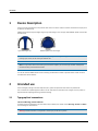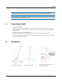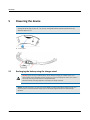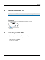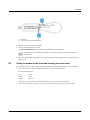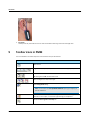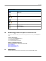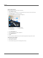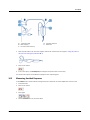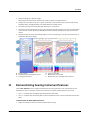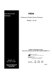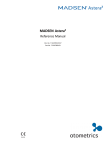
1
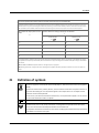
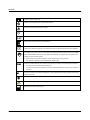
AURICAL FreeFit and the
OTOsuite PMM Module
User Guide
Doc. No. 7-50-1220-EN/03
Part No. 7-50-12200-EN
0459
Copyrightnotice
No part of this documentation orprogram may be reproduced, stored in a retrieval system, ortransmitted, in any form orby any
means, electronic, mechanical, photocopying, recording,or otherwise,without the prior written consent of GN Otometrics A/S.
Copyright© 2014, GN Otometrics A/S
Published in Denmark byGN Otometrics A/S, Denmark
All information, illustrations, and specifications in this manual are based on the latest productinformation available at the time of
publication. GN Otometrics A/Sreserves the right to make changes at any time without notice.
Versionrelease date
2014-02-20
Technicalsupport
Please contact your supplier.
2
Otometrics - AURICAL FreeFit
User Guide
Table of Contents
1
Device Description
4
2
Intended use
4
3
Unpacking FreeFit
5
4
Installation
5
5
Powering the device
6
6
Switching FreeFit on or off
7
7
Connecting FreeFit to PMM
7
8
FreeFit probes
8
9
Toolbar icons in PMM
10
10 Performing probe microphone measurements
11
11 Demonstrating hearing instrument features
15
12 Service, cleaning and maintenance
16
13 Other references
17
14 Standards
17
15 Power adaptor
17
16 Operating environment
18
17 Storage and handling
18
18 Manufacturer
18
19 Warning notes
19
20 Notes on EMC (Electromagnetic Compatibility)
20
21 Definition of symbols
23
Otometrics - AURICAL FreeFit
3
User Guide
1
Device Description
FreeFit is used for measuring the sound pressure level close to the client's eardrum as well as outside the ear by the pinna
for both ears simultaneously.
AURICAL FreeFit should only be charged using the type 1053 charger unit or the type 1081 AURICAL speaker unit from GN
Otometrics A/S.
Type 1053 charger unit
AURICAL speaker unit with charger
Note • This manual describes the assembly and use of the type 1053 charger unit. If you use the AURICAL speaker unit
to charge your FreeFit, see the manual for AURICAL Aud.
Note • For information about the Counseling and Simulations software, see the manual for AURICAL Visible Speech
and the Counseling and Simulations Module.
You use the OTOsuite PMM module and the Counseling and Simulations module to operate FreeFit. FreeFit cannot be
used without OTOsuite software.
2
Intended use
Users: audiologists, hearing instrument dispensers, ENTs, speech therapists and other health care professionals.
Use: to visualize the amplified signal recorded in the ear with reference information such as target curves to provide an
objective basis for adjusting the hearing instrument settings.
2.1
Typographical conventions
The use of Warning, Caution and Note
For safety reasons and appropriate use of the device and/or software, the manual contains Warnings, Cautions and Notes .
These headings are used as follows:
Warning • Indicates that there is risk of death or serious injury to the user or patient.
4
Otometrics - AURICAL FreeFit
User Guide
Caution • Indicates that there is a risk of injury to the user or patient or risk of damage to data or the device.
Note • Indicates that you should take special notice.
3
Unpacking FreeFit
1. Unpack the device carefully.
When you unpack the device and accessories, it is a good idea to keep the packing material in which they were
delivered. If you need to send the device in for service, the original packing material will protect against damage during transport, etc.
2. Visually inspect the equipment for possible damage.
If damage has occurred, do not put the device into operation. Contact your local distributor for assistance.
3. Check with the packing list to make sure that you have received all necessary parts and accessories. If your package is
incomplete, contact your local distributor.
4
Installation
Installation for desk top use
Otometrics - AURICAL FreeFit
Wall mount installation
Mounting the NOAHLink charger on the
FreeFit charger base plate
5
User Guide
5
Powering the device
Caution • Use only the following battery types:
Rechargeable (Ni-MH type) AA (R6) 1.2V, 1 pc. (Use only rechargeable batteries supplied by GN Otometrics A/S)
Alkaline AA (R6) 1.2V, 1 pc.
A. Press to open
5.1
Recharging the battery using the charger stand
Warning • If you are using an alkaline battery, do not attempt to charge your AURICAL FreeFit. Your
alkaline battery may be damaged and leak, and this may in turn cause damage to FreeFit. Place FreeFit in
the charger unit only if FreeFit contains a rechargeable battery.
Batteries should be removed if equipment is not likely to be used for some time.
Caution • To power the charger, you must use an IEC/UL 60601-01 certified power adaptor supplying 9 V DC, min.
300 mA and with a maximum available output of 15 W. The adapter supplied with the unit meets these specifications.
6
Otometrics - AURICAL FreeFit
User Guide
6
Switching FreeFit on or off
Warning • Unless you are charging FreeFit with the AURICAL Aud speaker unit, which has a medically isolated power
supply unit, do not attempt to use AURICAL FreeFit with clients while it is placed in the charger unit.
To switch on FreeFit
Press and hold the power button on top of the device until the status indicator light turns on. The status indicator will
light for about 3 seconds, and then go into periodic flashing.
To switch off FreeFit
Press and hold the power button on top of the device until the status indicator light turns off.
A. Power button
7
Connecting FreeFit to PMM
When you use PMM for the first time, run the configuration wizard to set up the connection between FreeFit and PMM.
After you have configured PMM for the first time, if FreeFit is turned on when you open the Control Panel in PMM, then
FreeFit will connect to PMM automatically. Otherwise, you can connect FreeFit as follows:
1. Switch on FreeFit.
2. In PMM, on the toolbar, click Control Panel .
3. In the control panel, click Connect.
Otometrics - AURICAL FreeFit
7
User Guide
8
FreeFit probes
A.
B.
C.
D.
Probe tube port
Marker ring
Ear cord
Tube guide
E. Probe tube
F. Transducer tube port (RECD probe only)
G. Probe housing
The ear cord is used to hang the probe below the client's ear. The probe tube is inserted into the ear canal for probe
microphone measurements. The probe tube has a black marker ring for marking how far into the ear canal the tube should
be inserted. The tube guide is used to stabilize the position of the probe tube. Before you make RECD measurements, you
fit a transducer tube on the transducer tube port.
8.1
Fitting probe tubes on the probes
A bag of silicone probe tubes is supplied together with FreeFit.
To fit a probe tube on the probe
Fit a probe tube to the probe tube port (thin metal tube) at the top of the probe housing. Gently push and twist the probe
tube down as far as possible over the port.
8.2
Calibrating the probe tubes
Note • To prevent cross-infection, use new probe tubes for each client.
1. Fit a new probe tube on the probe.
2. Insert the free end of the probe tube in the test location on the probe.
8
Otometrics - AURICAL FreeFit
User Guide
A. Probe tube
B. Test location for probe tube calibration
3. Make sure that FreeFit is connected to PMM.
4. Press the power button briefly on FreeFit.
The Probe Tube Calibration dialog box appears and the calibration starts automatically.
Alternatively, launch the wizard with the toolbar icon. (In RECD, pressing the power button starts an ear
measurement.)
5. If the tube calibration fails, check whether the tubes are blocked (pinched or clogged) and try to eliminate sources of
ambient noise.
8.3
Fitting the probes on the client and inserting the probe tubes
It is important that the probe tube for every measurement is inserted correctly and consistently in the ear of the client.
1. Place the black marker ring at the recommended distance from the tip of the probe tube.
Recommended distances are
men:
27 mm
women:
27 mm
children:
20-25 mm
In the case of children, otoscopy is especially recommended to prevent contact with the eardrum.
2. Place the ear cords with the probes over the ears of the client. Adjust the length of the ear cords, if required.
Otometrics - AURICAL FreeFit
9
User Guide
3. Be careful!
Carefully insert the probe tube into the ear canal until the black marker ring reaches the intertragal notch.
9
Toolbar icons in PMM
The icons available in the toolbar depend on the test function that you have selected.
Toolbar icons in PMM
Select device.
Toggle between Response, Gain, REIG and Predicted Aided Audiogram (PAA) views.
Select view:
HL: Hearing Level or SPL: Sound Pressure Level
Select audiogram view: Left, both or right
Open Fitting Details dialog.
Note • You must select the Use OpenREM calibration option if you are fitting an
open ear instrument.
Open Listen at the Eardrum/Listen in the Coupler window to record the signal at the
eardrum or in the coupler, or monitor the signal through your headphones.
Show/hide Curve Legend and Overlays box.
10
Otometrics - AURICAL FreeFit
User Guide
Toolbar icons in PMM
Switch to Feature-2-Benefit view.
(FreeStyle only)
Launch probe tube calibration wizard.
Toggle between standard calibration and OpenREM calibration.
Select previously measured RECD values.
Toggle between coupler fitting mode and Real Ear fitting mode.
Show/Hide OnTarget view, which displays the difference between the target curve and
the measured curve.
Switch to On Top mode.
10
Performing probe microphone measurements
When you start a new session in PMM, you must ensure the fitting parameters are set correctly in the Fitting Details dialog box.
To set the fitting parameters
1. Press F10 to open the Fitting Details dialog box.
2. Select the appropriate target rule.
3. Fill in the remaining fields in the dialog box.
Making Probe Microphone Measurements
The following sections describe the main procedures involved in PMM:
Measuring RECD ► 11
Measuring Unaided Response ► 13
Measuring Occluded Response ► 14
Measuring Aided Response ► 14
10.1
Measuring RECD
If you want to use measured RECD values for coupler based fitting, you can measure RECD in PMM as follows:
Otometrics - AURICAL FreeFit
11
User Guide
Measure coupler response:
Skip this procedure if you have a stored coupler measurement.
1. Open the RECD tab in PMM.
2. Indicate the type of coupler adapter you are using, and whether you are using an ear mold or foam insert tip.
3. Click Coupler Response... in the RECD Control Panel.
4. Attach the right RECD ear probe to the coupler in AURICAL HIT.
A. RECD coupling
B. BTE adapter tube
C. BTE (HA2) adapter
D. Transducer tubing
E. Transducer tube port
5. Click the Measure Right button.
6. Connect the left probe to the coupler in AURICAL HIT.
7. Click the Measure Left button.
8. Click OK.
9. Remove the probe from AURICAL HIT and remove the RECD coupling from the tubing of the BTE coupler.
Then measure real ear response:
1. Attach the probes to the FreeFit.
2. Perform probe tube calibration.
3. Connect the RECD coupling to the ear mold tubing (or foam insert tip).
12
Otometrics - AURICAL FreeFit
User Guide
A. Transducer tubing
B. RECD coupling
C. Ear mold or foam insert tip
D. Transducer tube port
E. Probe tube
4. Place the probe tubes in the client’s ears together with the ear molds or foam insert tips (see Fitting the probes on
the client and inserting the probe tubes ► 9).
5. Select ear to measure.
6. In the control panel, click Ear Response (or briefly press the power button on the FreeFit).
The measured ear response and the RECD are displayed in their respective graphs.
10.2
Measuring Unaided Response
In the Unaided screen, measure without hearing instruments to determine the natural amplification of the ear canal.
1. Insert probe tube.
2. Select ear to measure.
3. Select graph.
4. Click the Unaided button on the Control Panel.
Otometrics - AURICAL FreeFit
13
User Guide
Note • In an unaided measurement, we usually expect a peak on the measurement curve around the 3kHz frequency of
about 10-20 dB SPL.
A. UCL
B. Audiogram
10.3
C. Peak around 3 kHz
D. Measurement curve
Measuring Occluded Response
In the Occluded Response screen, measure with muted hearing instruments in ears to measure the occlusion or openness
of the fitting.
1. Place the hearing instrument on the ear of the patient, with the probe tube inserted in the ear canal. Ensure the hearing instrument is muted or turned off.
2. Click the Occluded button on the Control Panel.
When you compare the REUR to the REOR, you can see the impact of the occlusion of the ear canal.
10.4
Measuring Aided Response
In the Aided screen, measure the gain that the hearing instruments are providing in relation to a specified prescriptive fitting target.
1. Place the hearing instrument on the ear of the patient, with the probe tube inserted in the ear canal.
Note • For Coupler based fitting, select the Coupler based fitting icon on the toolbar and attach the hearing
instrument to the coupler in the AURICAL HIT (see the manual for AURICAL HIT).
14
Otometrics - AURICAL FreeFit
User Guide
2. Switch the hearing aid on without moving it.
All the hearing instrument features should be left on with the general use program selected.
3. Configure the control panel to play up to 5 signals. For example: 3 input levels for a speech or speech-like stimulus:
Soft (50/55 dB SPL), Average (65 dB SPL) and Loud (80 dB SPL) plus an MPO stimulus.
4. Present the various input levels and MPO signal separately or in one sequence.
5. Compare the measured aided response curve to the prescriptive target values (dashed curve) and the measured MPO
curve to the UCL. Consider adjusting the MPO (Maximum Power Output) if indicated by any report of loudness discomfort.
6. Adjust the hearing instrument with the fitting software to achieve the desired gain, and repeat the measurements to
evaluate the effects of the changes.
A. Sequence button
B. Measurement buttons for different stimuli
C. Curve legend for button 1.
11
D. Target curve for MPO.
E. Measurement curve for MPO.
F. Measurement curve and target curve for button 1.
Demonstrating hearing instrument features
Use the Noise Reduction screen to evaluate and demonstrate the hearing instrument’s noise reduction feature. Each
Noise Reduction test is an automatic sequence that contains two curves (with a delay between the two curves):
•
Curve 1 – a snapshot taken immediately before Noise Reduction takes effect.
•
Curve 2 – a snapshot taken automatically after the selected Adaptation Interval, when the Noise Reduction has taken
effect.
To demonstrate the Noise Reduction feature:
1. Program the hearing instrument for the desired Noise Reduction setting.
Otometrics - AURICAL FreeFit
15
User Guide
2. Configure the measurement buttons to demonstrate the conditions you prefer. For each button, select the time difference between the two measurements (Curve 1 and Curve 2).
3. Click a measurement button in the control panel.
The snapshot curves are displayed in the graph and the overall Noise Reduction is displayed in the curve legend.
The Feature-2-Benefit view gives you the opportunity to see and show the gain difference in an easy to understand graph.
The FreeStyle test screen is similar to the other PMM test screens but with numerous possibilities to customize protocols.
12
Service, cleaning and maintenance
Warning • Under no circumstances disassemble FreeFit or the FreeFit charger. Contact your supplier. Parts inside
FreeFit and the FreeFit charger must only be checked or serviced by authorized personnel.
12.1
Service
For the sake of safety and in order not to void the warranty, service and repair of electro-medical equipment should be carried out only by the equipment manufacturer or by service personnel at authorized workshops. In case of any defects,
make a detailed description of the defect(s) and contact your supplier. Do not use a defective device.
12.2
Cleaning
Use a soft, slightly damp cloth with a small amount of mild detergent or approved non-caustic medical grade disinfectant
wipes to clean the unit and charger according to local infection control regulations.
Caution • Keep the unit away from liquids. Do not allow moisture inside the unit.
Caution • Never immerse the FreeFit probes into water or other cleaning solutions.
Caution • No part of FreeFit or its accessories is suitable for autoclaving or thermal disinfection/sterilization methods.
Probe tubes, tube guides and ear cords
These parts are in constant contact with your clients.
16
•
Probe tubes:
The only part which is inserted into the ear canal during PMM testing is the Probe tube. These tubes are disposable,
and should only be used once per client.
•
Tube guides and ear cords:
Use a soft, slightly damp cloth with a small amount of detergent to clean the cords and the tube guides.
Otometrics - AURICAL FreeFit
User Guide
Disposal
There are no special requirements regarding the disposal of the silicone test tubes, i.e. they can be discarded according to
local regulations.
12.3
Maintenance
Annual calibration
FreeFit and the FreeFit probes must be calibrated once a year by your authorized service department.
13
Other references
For more information, see the online Help in OTOsuite, which contains detailed reference information about FreeFit and
PMM, and other OTOsuite products.
For instructions on installing OTOsuite, see the OTOsuite Installation Guide, which you can find on the OTOsuite installation medium (disk or memory stick).
14
15
Standards
Safety:
IEC 60601-1, UL 60601-1, CAN/CSA -C22.2 NO 601.1-90
AURICAL FreeFit: IEC 60601-1, Internally Powered, Type BF, IPX0
EMC:
IEC 60601-1-2, EN 300 328-2, EN 301 489-17
Power adaptor
BRIDGEPOWER CORP
MENB1010A0903B01
Output: 9 VDC, 1.10 A
Input: 100-240 V, 50-60 Hz
DONGGUAN SHILONG FUHUA ELECTRONIC CO., LTD.
UE08WCP-090056SPA
Output: 9 VDC, 0.56 A
Input: 100-240 V, 50-60 Hz
Use only the power adaptor supplied with the instrument.
Otometrics - AURICAL FreeFit
17
User Guide
16
Operating environment
Temperature:
+15°C to +35°C (59°F to +95°F)
Relative humidity:
30 to 90%, non-condensing
Warm-up time:
< 1 min.
Air pressure:
600 hPa to 1060 hPa
Operation at temperatures below -20°C or above +60°C may cause permanent damage.
17
18
Storage and handling
Temperature:
-20°C to +60°C (-4°F to +140°F)
Rel. humidity:
< 90%, non-condensing
Air pressure:
500 hPa to 1060 hPa
Manufacturer
GN Otometrics A/S
9 Hoerskaetten, DK-2630 Taastrup
Denmark
+45 45 75 55 55
+45 45 75 55 59
www.otometrics.com
18.1
Responsibility of the manufacturer
The manufacturer is to be considered responsible for effects on safety, reliability, and performance of the equipment only
if:
•
All assembly operations, extensions, re-adjustments, modifications or repairs are carried out by the equipment manufacturer or personnel authorized by the manufacturer.
•
The electrical installation to which the equipment is connected complies with EN/IEC requirements.
•
The equipment is used in accordance with the instructions for use.
The manufacturer reserves the right to disclaim all responsibility for the operating safety, reliability and performance of
equipment serviced or repaired by other parties.
18
Otometrics - AURICAL FreeFit
User Guide
19
Warning notes
This manual contains information and warnings, which must be followed to ensure the safe performance of the devices and
software covered by this manual. Local government rules and regulations, if applicable, should also be followed at all times.
AURICAL FreeFit should only be charged using the type 1053 charger unit or the type 1081 AURICAL speaker unit
from GN Otometrics A/S.
Unless you are charging FreeFit with the AURICAL Aud speaker unit, which has a medically isolated power supply
unit, do not attempt to use AURICAL FreeFit with clients while it is placed in the charger unit.
1. There are no user-serviceable parts inside the cabinet of the device or charger. For the sake of safety and in order not
to void the warranty, service and repair of electro-medical equipment should be carried out only by the equipment
manufacturer or by service personnel at authorized workshops. In case of any defects, make a detailed description of
the defect(s) and contact your supplier. Do not use a defective device.
2. Keep the unit away from liquids. Do not allow moisture inside the unit.
3. Do not use the instrument in the presence of flammable anesthetics (gases).
4. Unwanted noise may occur if the instrument is exposed to a strong radio field. Such noise may interfere with the process of recording an accurate audiogram and fitting a hearing instrument. Many types of electrical devices, e.g. mobile
telephones, may generate radio fields. We recommend that the use of such devices in the vicinity of this instrument
be restricted as much as possible.
5. Changes or modifications not expressly approved by the manufacturer could void the user's authority to operate the
equipment.
6. This equipment has been tested and found to comply with the limits for a Class B digital device, pursuant to part 15 of
the FCC Rules. These limits are designed to provide reasonable protection against harmful interference in a residential
installation. This equipment generates, uses and can radiate radio frequency energy and, if not installed and used in
accordance with the instructions, may cause harmful interference to radio communications. However, there is no guarantee that interference will not occur in a particular installation. If this equipment does cause harmful interference to
radio or television reception, which can be determined by turning the equipment off and on, the user is encouraged
to try to correct the interference by one or more of the following measures:
–
Reorient or relocate the receiving antenna.
–
Increase the separation between the equipment and receiver.
–
Connect the equipment into an outlet on a circuit different from that to which the receiver is connected.
–
Consult the dealer or an experienced radio/TV technician for help.
7. For use in Canada: To prevent radio interference to the licensed service, this device is intended to be operated
indoors and away from windows to provide maximum shielding. Equipment (or its transmit antenna) that is installed
outdoors is subject to licensing.
8. No parts may be eaten, burnt, or in any way used for purposes other than the applications defined in the Intended Use
section of this manual.
9. The device and charger unit can be disposed of as normal electronic waste, according to local regulations. Please
investigate local regulations concerning the disposal of rechargeable and alkaline batteries.
10. For safety reasons, accessories connected to the equipment's outlet fittings must be identical to the type supplied
with the system.
Otometrics - AURICAL FreeFit
19
User Guide
11. It is recommended that an annual calibration be performed on accessories containing transducers. Furthermore, it is
recommended that calibration be performed if the equipment has suffered any potential damage (e.g. headphones
dropped on the floor).
12. To comply with EN 60601-1-1 computer and printer must be placed out of reach of the client, i.e. not closer than
approx. 1.5 meters/5 ft.
13. In the United States of America, Federal law restricts this device to sale by or on the order of a licensed physician.
14. It is recommended to install the unit in an environment that minimizes the amount of static electricity. For example,
anti-static carpeting is recommended.
15. The charger unit should be kept away from the client area.
20
Notes on EMC (Electromagnetic Compatibility)
•
AURICAL FreeFit is part of a medical electrical system and is thus subject to special safety precautions. For this reason,
the installation and operating instructions provided in this document should be followed closely.
•
Portable and mobile high-frequency communication devices, such as mobile phones, may interfere with the functioning of AURICAL FreeFit.
Guidanceand manufacturer's declaration - electromagnetic emissions for all equipment and systems
AURICAL FreeFit is intended for use in the electromagnetic environment specified below. The user of AURICAL FreeFit should ensure that it is used in such an
environment.
Emissionstest
Compliance
Electromagnetic environment - guidance
RF emissions
Group 1
AURICAL FreeFit uses RF energy only for its internal function. Therefore, its RF emissionsare
CISPR 11
RF emissions
very low and are not likely to cause any interference in nearby electronic equipment.
Class B
CISPR 11
AURICAL FreeFit is suitable for use in all environments, including domestic environments and
those directly connected to the public low-voltage power supply network that supplies
buildingsused for domestic purposes.
Harmonic emissions IEC 61000- 3-2
Not applicable
Voltagefluctuations/flicker emissionsIEC Not applicable
61000-3-3
20
Otometrics - AURICAL FreeFit
User Guide
Guidanceand manufacturer's declaration - electromagnetic immunity for all equipment and systems
AURICAL FreeFit is intended for use in the electromagnetic environment specified below. The user of AURICAL FreeFit should ensure that it is used in such an
environment.
Immunitytest
IEC 60601
Compliancelevel
Electromagnetic environment - guidance
test level
Electrostatic
+/- 6 kV contact
+/- 6 kV contact
Floors should bewood, concrete or ceramic tile. If floors are covered with syn-
discharge(ESD)
+/- 8 kV air
+/- 8 kV air
thetic material, the relative humidity should be at least 30%.
3A/m
3A/m
Power frequency magnetic fields should be at levels characteristic of a typical loc-
IEC 61000-4-2
Power frequency
(50/60 Hz) magnetic
ation in a typical commercial or hospital environment.
field
IEC 61000-4-8
Note • UT is the AC mains voltage prior to application of the test level.
Otometrics - AURICAL FreeFit
21
User Guide
Guidanceand manufacturer's declaration - electromagnetic immunity - for equipment and systems that are NOT life-supporting
AURICAL FreeFit is intended for use in the electromagnetic environment specified below. The user of AURICAL FreeFit should ensure that it is used in such an
environment.
Immunity test
IEC 60601
Compliance level
Electromagnetic environment - guidance
3V/m
Portableand mobile RF communications equip-
test level
Radiated RF
3V/m
IEC 61000-4-3
80MHz to 2.5 GHz
ment should be used no closer to any part of
AURICAL FreeFit, including cables, than the
recommended separation distance calculated
from the equation applicable to the frequency
of the transmitter.
Recommended separation distance:
d = 1.2
for 80MHz to 800 MHz
d = 2.3
for 80MHz to 2.5 GHz,
where P is the maximum output power rating of
the transmitter in watts (W) according to the
transmitter manufacturer and d is the recommended separation distance in metres (m).
Field strengthsfrom fixed RF transmitters, as
determined by an electromagnetic site survey, a
should beless than the compliance level in each
frequency range. b
Interference may occur in the vicinity of equipment marked with this symbol:
Note 1:At 80 MHzand 800 MHz the separation distancefor the higher frequency range applies.
Note 2:These guidelinesmay not apply in all situations. Electromagnetic propagation is affected by absorption and reflection from structures, objects and
people.
a. Field strengths from fixed transmitters, such as base stations for radio (cellular/cordless) telephones and land mobile radios,amateur radio, AM and
FM radio broadcast and TV broadcast cannot be predicted theoretically with accuracy.To assess the electromagnetic environment due to fixed RF
transmitters, an electromagnetic site survey should be considered. If the measured field strength in the location in which AURICAL FreeFit is used
exceeds the applicable RF compliance level above, the AURICAL FreeFit should be observed to verify normal operation. If abnormalperformance is
observed,additional measures might be necessary, such as reorienting or relocatingAURICAL FreeFit.
b. Over the frequency range 150 kHz to 80 MHz, field strengths should be less than 3 V/m.
22
Otometrics - AURICAL FreeFit
User Guide
Recommended separation distances between portable and mobile RF communications equipment and AURICAL FreeFit
The AURICAL FreeFitis intended for use in an electromagnetic environment in which radiated RF disturbances are controlled. The customer or the user of the
AURICAL FreeFit can help prevent electromagnetic interference by maintaining a minimum distance between portableand mobile RF communications equipment (transmitters) and the AURICAL FreeFitasrecommended below, according to the maximum output power of the communications equipment.
Rated maximum output power of trans- Separation distance according to frequency of transmitter
mitter
m
W
80MHz to 800 MHz
800 MHzto 2,5 GHz
d = 1.2
d = 2.3
0.01
0.12
0.23
0.1
0.38
0.73
1
1.2
2.3
10
3.8
7.3
100
12
23
For transmitters rated at a maximum output power not listed above, the recommended separation distance d in metres (m) can be estimated using the equation applicable to the frequency of the transmitter, where P is the maximum output power rating of the transmitter in watts (W) according to the transmitter
manufacturer.
Note 1:At 80 MHzand 800 MHz the separation distancefor the higher frequency range applies.
Note 2:These guidelinesmay not apply in all situations. Electromagnetic propagation is affected by absorption and reflection from structures, objects and
people.
21
Definition of symbols
Electronic equipment covered by the Directive 2002/96/EC on waste electrical and electronic equipment
(WEEE).
All electrical and electronic products, batteries, and accumulators must be taken to separate collection at
the end of their working life. This requirement applies in the European Union. Do not dispose of these
products as unsorted municipal waste.
You can return your device and accessories to Otometrics, or to any Otometrics supplier. You can also contact your local authorities for advice on disposal.
Identifies the correct position of the battery inside the battery compartment.
Interference may occur in the vicinity of the device. Local regulations and precautions for other equipment in the environment should always be followed to avoid interference.
The separation distance from this device to other devices complying with standard immunity requirements
in IEC 60601-1-2 is minimum 0.35 m/1ft.
Otometrics - AURICAL FreeFit
23
User Guide
Suitable for direct current only.
In France, it is only permitted to use the device indoors.
Consult user manual for warnings and cautions.
Follow instructions for use.
Consult instructions for use.
Complies with Type BF requirements of IEC60601-1.
Complies with Medical Devices Directive 93/42/EEC.
Complies with the Radio Equipment and Telecommunications Terminal Equipment Directive 1999/5/EC.
XXXX
C
UL
®
US
The installation must be carried out in accordance with Medical Electrical Systems clause 16 in IEC 606011 (3rd), AAMI ES60601-1 and CSA C22.2 NO. 60601-1-08-CAN/CSA. The supplementary provisions on the
reliability of electro-medical systems.
It is a general rule for all electrical equipment used in the proximity of the client that:
•
The connected equipment must comply with IEC 60601-1 (3rd).
This device complies with part 15 of the FCC rules. Operation is subject to the following two conditions:
•
This device must not cause harmful interference.
•
This device must accept any interference received, including interference that may cause undesired
operation.
The term”IC” before the certification/registration number signifies that the Industry Canada technical specifications were met.
Do not reuse.
Used in error message dialogs if software program fails. See the detailed information in the dialog box.
Manufacturer and date of manufacture.
24
Otometrics - AURICAL FreeFit