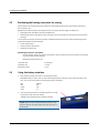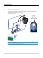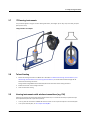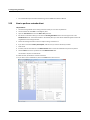
1
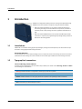
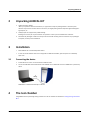
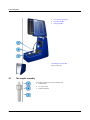
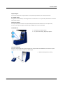
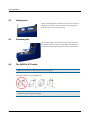
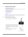
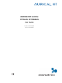
AURICAL HIT and the
OTOsuite HIT Module
User Guide
Doc. No. 7-50-1230-EN/02
Part No. 7-50-12300-EN
Copyrightnotice
No part of this documentation orprogram may be reproduced, stored in a retrieval system, ortransmitted, in any form orby any
means, electronic, mechanical, photocopying, recording,or otherwise,without the prior written consent of GN Otometrics A/S.
Copyright© 2014, GN Otometrics A/S
Published in Denmark byGN Otometrics A/S, Denmark
All information, illustrations, and specifications in this manual are based on the latest productinformation available at the time of
publication. GN Otometrics A/Sreserves the right to make changes at any time without notice.
Versionrelease date
2014-02-25
Technicalsupport
Please contact your supplier.
2
Otometrics - AURICAL HIT
Table of Contents
1
Introduction
4
2
Unpacking AURICAL HIT
5
3
Installation
5
4
The test chamber
5
5
Testing hearing instruments
9
6
Maintenance and Calibration
15
7
Other references
16
8
Standards
16
9
Operating environment
16
10 Transport and storage
17
11 Definition of symbols
17
12 Warning notes
18
13 Manufacturer
19
Otometrics - AURICAL HIT
3
1 Introduction
1
Introduction
AURICAL HIT is designed for Hearing Instrument Testing and Coupler-Based Fitting.
AURICAL HIT connects via USB to a computer running the OTOsuite software.
1.1
•
With the OTOsuite HIT Module you can perform traditional hearing instrument testing according to either the ANSI or IEC test protocols, and obtain a
consistent picture of every hearing instrument, regardless of manufacturer or
type.
•
With the OTOsuite PMM Module you can perform Probe Microphone Measurements in a coupler for pre-programming and pre-fitting hearing instruments
without the client being present.
Intended use
AURICAL HIT is intended for testing purposes by audiologists, hearing instrument dispensers, and other health care professionals in testing programmable hearing instruments.
Required qualifications
It is assumed that the user has a basic knowledge of how to compare the results of the hearing instrument tests with the
specifications from the hearing instrument manufacturer and to detect typical malfunctions of the hearing instrument.
1.2
Typographical conventions
The use of Warning, Caution and Note
For safety reasons and appropriate use of the device and/or software, the manual contains Warnings, Cautions and Notes .
These headings are used as follows:
Warning • Indicates that there is risk of death or serious injury to the user or patient.
Caution • Indicates that there is a risk of injury to the user or patient or risk of damage to data or the device.
Note • Indicates that you should take special notice.
4
Otometrics - AURICAL HIT
2 Unpacking AURICAL HIT
2
Unpacking AURICAL HIT
1. Unpack the device carefully.
When you unpack the device and accessories, it is a good idea to keep the packing material in which they were
delivered. If you need to send the device in for service, the original packing material will protect against damage during transport, etc.
2. Visually inspect the equipment for possible damage.
If damage has occurred, do not put the device into operation. Contact your local distributor for assistance.
3. Check with the packing list to make sure that you have received all necessary parts and accessories. If your package is
incomplete, contact your local distributor.
3
3.1
Installation
•
Place AURICAL HIT on an absolutely stable surface.
•
In order to exclude ambient noise and to comply with the ANSI S3.22 standard, place the system in a moderately
quiet room.
Connecting the device
1. Install OTOsuite on the PC. See the OTOsuite Installation Guide.
2. Connect the USB cable from the USB socket under AURICAL HIT to a USB socket in the PC. AURICAL HIT is powered by
the PC.
AURICAL HIT is selected automatically in OTOsuite.
4
The test chamber
Using AURICAL HIT and positioning hearing instruments in the test chamber are described in Testing hearing instruments
► 9.
Otometrics - AURICAL HIT
5
4 The test chamber
A. The coupler assembly ► 6
B. Elevation plate ► 8
C. Cable groove ► 8
The AURICAL HIT handle ► 8
(some models only)
4.1
The coupler assembly
The coupler assembly consists of the following parts:
A. Coupler adapter
B. 2 cc coupler cavity
C. Coupler microphone
6
Otometrics - AURICAL HIT
4 The test chamber
Coupler adapter
The Accessory Box provides a range of adapters for easy positioning of different types of hearing instruments.
2 cc coupler cavity
During tests in the test chamber, the hearing instrument is connected to a 2 cc coupler cavity manufactured in accordance
with the ANSI standard.
Coupler microphone
The coupler microphone is located in a coupler bottom piece which must be attached to the 2 cc coupler cavity.
You can use the coupler microphone either directly in AURICAL HIT or in the Accessory Box.
In AURICAL HIT
A. BTE testing - Low coupler position
B. ITE, RIE, thin-tube testing - High coupler position
In the Accessory Box
Connect the mini-jack cable from the Accessory Box to the mini-jack socket under AURICAL HIT, and insert the coupler
microphone in the microphone socket in the Accessory Box.
A. Wireless hearing instrument testing
Otometrics - AURICAL HIT
7
4 The test chamber
4.2
Cable groove
Wrap the programming cable of the hearing instrument once around the
cable groove. This prevents the hearing instrument from being pulled
out of place when you close the lid for testing.
4.3
Elevation plate
Use the elevation plate to facilitate positioning of wireless transmitters
and body worn hearing instruments at a level where the microphone or
microphones are approximately centered in relation to the loudspeaker.
4.4
The AURICAL HIT handle
Note • This only applies to models equipped with a carrying handle.
The handle is designed for carrying AURICAL HIT.
Caution • If you carry AURICAL HIT by its handle, do not use your other hand to support it by the lid, as this may
cause the lid to open and squeeze your fingers.
8
Otometrics - AURICAL HIT
5 Testing hearing instruments
5
Testing hearing instruments
Testing a hearing instrument involves the following main tasks:
1.
Calibrating the reference microphone
Otometrics recommends that you calibrate the reference microphone daily or weekly. Set up the interval to suit your purposes. See Calibrating the reference microphone ► 9.
2.
Positioning the hearing instrument
General instructions are described in
• Traditional BTE hearing instruments ► 11
•
Thin-tube hearing instruments ► 12
•
ITE hearing instruments ► 13
3.
Testing
When you have positioned the hearing instrument correctly, you can test it using the OTOsuite HIT module as described
in How to perform a standard test ► 14 , or you can perform coupler-based fitting as described in the AURICAL FreeFit
and the Probe Microphone Measurements User Manual.
5.1
Calibrating the reference microphone
1. Launch OTOsuite and select the HIT module in the Navigation panel.
2. Position the microphones in the center of the test chamber.
3. Position the reference microphone (1) pointing straight down from above and
centered 1-2 millimeters above the coupler measurement microphone (3).
4. During calibration the microphones must have the exact same distance to the
main loudspeaker (2), along the Z axis. You can ensure this by looking at the
test chamber from the side when you adjust the reference microphone position for calibration.
5. Close the lid.
6. Select Tools > AURICAL HIT Calibration > Reference Microphone.
7. Follow the on-screen instructions.
Otometrics - AURICAL HIT
9
5 Testing hearing instruments
5.2
Positioning the hearing instrument for testing
How you position the hearing instrument for testing in the test chamber depends on the type of hearing instrument or
device you wish to test.
Regardless of form factor (the type of hearing instrument), the only two important things to remember are:
• Aligning directional microphones along the loudspeaker axis.
•
Positioning the reference microphone as close as possible to the front microphone of the hearing instrument without
touching it.
You can position the hearing instrument to perform all standard hearing instrument tests without repositioning the hearing instrument between the individual tests:
• acoustic measurements,
•
inductive telecoil measurements,
•
directional microphone test.
Positioning the reference microphone
–
As a rule of thumb, position the reference microphone as close as possible to the front microphone of the hearing
instrument without actually touching it.
Maximum permitted distances are:
5.3
Vertically (Y axis)
8 mm (above)
Sideways (X axis)
±12 mm
Back-to-front (Z axis)
±3 mm
Using the battery simulator
1. Select a battery simulator and insert it in the hearing instrument.
With AURICAL HIT you receive a set of 4 color-coded battery simulators, which are used to power the hearing instrument. They are also used as probes for measuring the power consumption.
Red
Blue
Yellow
Green
10A/230
675
312
13
2. Insert the mini-jack connector of the battery simulator in the battery simulator socket in the test chamber.
AURICAL HIT automatically detects the battery simulator.
Caution • When you have connected the battery simulator, make
sure that it does not touch other metal parts as this may short-circuit the system.
10
Otometrics - AURICAL HIT
5 Testing hearing instruments
5.4
Coupler adapters
Adapters for use with the 2 cc coupler are snapped onto the coupler cavity.
•
HA-2 (BTE)
Traditional BTE hearing instruments ► 11
•
HA-1 (ITE, RIE, thin-tube)
Thin-tube hearing instruments ► 12 and ITE hearing instruments ► 13
To fix the hearing instrument on the adapter, snap the adapter off the coupler cavity, and attach the hearing instrument to
the adapter outside the test chamber.
5.5
Traditional BTE hearing instruments
This procedure applies to any type of standard BTE hearing instruments with traditional ear molds.
Using the HA-2 adapter and BTE adapter tube
Otometrics - AURICAL HIT
11
5 Testing hearing instruments
5.6
Thin-tube hearing instruments
This type of procedure applies to any type of thin-tube hearing instruments, including instruments with the Receiver In
the Ear (RIE)/Receiver In the Canal (RIC), and pre-bent tubing.
Using the HA-1 ITE adapter
Note • If you place some acoustic putty on the receiver wire this will shift its resonance frequency. This will prevent
the wire from vibrating and creating feedback during testing.
12
Otometrics - AURICAL HIT
5 Testing hearing instruments
5.7
ITE hearing instruments
This procedure applies to any type of custom hearing instruments, including ITE (In The Ear), ITC (In The Canal), CIC (Completely In the Canal).
Using the HA-1 ITE adapter
5.8
Telecoil testing
1. Position the hearing instrument in AURICAL HIT as described in Traditional BTE hearing instruments ► 11, Thintube hearing instruments ► 12 or ITE hearing instruments ► 13, so that the maximum field strength will be
achieved for the hearing instrument.
During telecoil testing AURICAL HIT automatically detects the orientation of the hearing instrument.
2. Enable telecoil mode in the hearing instrument.
3. Close the lid and start testing.
5.9
Hearing instruments with wireless transmitters (e.g. FM)
When you test hearing instruments with wireless sound transmission, it is sometimes necessary to separate the input
device (transmitter) from the output device (receiver).
•
To do so, place the transmitter in AURICAL HIT and the receiver on the coupler microphone in the Accessory Box.
•
To set up the Accessory Box, see The coupler assembly ► 6.
Otometrics - AURICAL HIT
13
5 Testing hearing instruments
•
5.10
For a detailed description of traditional FM testing, see the AURICAL HIT Reference Manual.
How to perform a standard test
The procedure
1. Launch the fitting software for the hearing instrument so that you can control its parameters.
2. Launch OTOsuite and select HIT in the Navigation panel.
3. Open the Test Selector and select the ANSI or IEC special test.
4. If OTOsuite is used without Noah, you can fill out the Hearing Instrument fields in the lower right corner of the
Standard Tests screen. These fields are filled in automatically when you use OTOsuite with Noah together with the fitting software for the hearing instrument.
5. Position the hearing instrument so that it is ready for testing, and switch it on.
6. If you wish to measure the Battery Consumption, make sure that you connect the battery simulator.
7. Close the lid.
8. If needed, click the arrow buttons in the Measurements table to include the individual tests you wish to perform.
9. Click the Start button in the top left corner of the Measurements table.
This will start a sequence of selected tests.
10. Make sure that you follow the on-screen instructions.
11. If you wish to redo an individual test, click on the Start button next to the test.
14
Otometrics - AURICAL HIT
6 Maintenance and Calibration
5.11
How to test the directional microphone
Directionality measurements as described in the hearing instrument test standards cannot be performed with regular desktop test chambers such as AURICAL HIT. Such measurements require large anechoic chambers. Small test chambers always
exhibit acoustic reflections that obscure the true directional behavior of the hearing instrument.
However, in AURICAL HIT you can make a functional test of the directional microphone in a hearing instrument. In this
test, the signal is first presented to the front of the hearing instrument and then to the back of the hearing instrument.
This is done automatically when you start a Directional Test. The signal used for this test is a flat spectrum Broad Band
Noise, band-pass filtered between 750 Hz and 5 kHz, and presented at 70 dB SPL.
The procedure
1. Position the hearing instrument as described in Traditional BTE hearing instruments ► 11, Thin-tube hearing instruments ► 12 and ITE hearing instruments ► 13 depending on the type of hearing instrument.
2. In the field Directionality Adaptation in the OTOsuite HIT module, you can define the duration of the signal presentation before the actual measurement is made. This value accommodates any adaptational behavior of the hearing
instrument. Adaptive directionality often takes 10 to 15 seconds or more before the directionality of the hearing
instrument is fully efficient.
3. You can either combine the Directional Test with your standard test sequence by checking the sequence checkbox,
or run it separately by clicking the Start button.
The result
The Directional Test result is shown as a 1/3 octave curve of the difference between the measurement with noise presented from the main loudspeaker and the measurement with noise presented from the rear loudspeaker. The numerical directionality result shown in the Measurements table indicates the average front/back difference in the measured
frequency range.
The Measurements table also includes the adaptation interval used in seconds.
6
Maintenance and Calibration
Warning • Under no circumstances disassemble AURICAL HIT. Contact your supplier. Parts inside AURICAL HIT must
only be checked or serviced by authorized personnel. Calibration of the coupler microphone, and calibration of a new
reference or coupler microphone must only be performed by authorized personnel.
Maintenance
AURICAL HIT requires no preventive maintenance except for cleaning and regular calibration of the reference microphone.
Repair
For any type of repair, please contact your supplier.
For the sake of safety and in order not to void the warranty, service and repair of electro-medical equipment should be carried out only by the equipment manufacturer or by service personnel at authorized workshops. In case of any defects,
make a detailed description of the defect(s) and contact your supplier. Do not use a defective device.
Otometrics - AURICAL HIT
15
7 Other references
6.1
Cleaning
There are no specific requirements to sterilization or disinfection of the device.
Cleaning the device
Make sure that the device is kept clean and free of dust:
• Remove dust using a soft brush.
•
To clean the cabinet, use a soft, slightly damp cloth with a small amount of mild detergent on it.
Caution • Keep the unit away from liquids. Do not allow moisture inside the unit.
Adapters
If needed, remove any acoustic putty residue, and use an alcohol based wipe to clean the adapter.
7
Other references
For more information, see the following manuals on your product CD:
•
AURICAL HIT and the OTOsuite HIT Module Reference Manual (English only)
•
AURICAL FreeFit and the Probe Microphone Measurements Module Reference Manual (English only)
•
OTOsuite SOftware User Manual
See also the OTOsuite Installation Guide provided in the OTOsuite software DVD box.
8
9
Standards
AURICAL HIT
CE-marked according to the Electrical Safety Directive IEC 610101
Test standards
ANSI S3.22
IEC 60118-7
EMC
IEC 61326-1
Operating environment
Operating environment
16
Indoors
Otometrics - AURICAL HIT
10 Transport and storage
10
11
Operating temperature range
15 to 35 ºC (59 to 95 ºF)
Maximum relative humidity
Maximum relative humidity 80% for temperatures up to 31ºC (88
ºF) decreasing linearly to 50% relative humidity at 40 ºC (104 ºF).
Altitude
Up to 2,000 m (6,562 feet)
Warm-up time
< 15 min
Transport and storage
Temperature:
-15ºC to +55ºC (5ºF to 131ºF)
Air humidity:
10% to 90%, non-condensing
Definition of symbols
Electronic equipment covered by the Directive 2002/96/EC on waste electrical and electronic equipment
(WEEE).
All electrical and electronic products, batteries, and accumulators must be taken to separate collection at
the end of their working life. This requirement applies in the European Union. Do not dispose of these
products as unsorted municipal waste.
You can return your device and accessories to Otometrics, or to any Otometrics supplier. You can also contact your local authorities for advice on disposal.
Consult user manual for warnings and cautions.
Consult instructions for use.
Complies with Medical Devices Directive 93/42/EEC.
C
UL
®
UL listing mark.
US
LISTED
HEARING AID TESTER
XXXX
USB socket for connecting AURICAL HIT to a computer.
Socket for connecting external coupler microphone.
Otometrics - AURICAL HIT
17
12 Warning notes
12
Warning notes
Warning • For warning notes applying to AURICAL HIT when in use with AURICAL FreeFit, see the warning notes in
the AURICAL FreeFit Safety section in the AURICAL FreeFit documentation.
1. The device is intended for testing purposes by audiologists, hearing instrument dispensers, and other health care professionals in testing programmable hearing instruments.
2. Accidental damage and incorrect handling can have a negative effect on the functionality of the device. Contact your
supplier for advice.
3. For the sake of safety and in order not to void the warranty, service and repair of electro-medical equipment should
be carried out only by the equipment manufacturer or by service personnel at authorized workshops. In case of any
defects, make a detailed description of the defect(s) and contact your supplier. Do not use a defective device.
4. It is recommended to install the unit in an environment that minimizes the amount of environmental noise.
5. It is recommended to install the unit in an environment that minimizes the amount of static electricity. For example,
anti-static carpeting is recommended.
6. Do not store or operate the device at temperatures and humidity exceeding those stated in Technical Specifications,
Transport and storage ► 17.
7. Keep the unit away from liquids. Do not allow moisture inside the unit.
8. Do not use the instrument in the presence of flammable anesthetics (gases).
9. No parts may be eaten, burnt, or in any way used for purposes other than the applications defined in the Intended Use
section of this manual.
10. The device should be turned off before any connections are established. To disconnect the device from the power
supply, pull the USB plug out of the PC, or shut down the PC.
11. We recommend that an annual calibration be performed on accessories containing microphones. Furthermore, we
recommend that calibration be performed if the equipment has suffered any potential damage (e.g. microphone
dropped on the floor). Note that calibration has been performed only on the microphones supplied! If you wish to use
other microphones for testing with the device, please contact your local distributor first.
12. To prevent cross-infection, use fresh acoustic putty when you test the next hearing instrument.
13. For safety reasons, accessories connected to the equipment's outlet fittings must be identical to the type supplied
with the system.
14. Unwanted noise may occur if the device is exposed to a strong radio field. Such noise may interfere with the process
of testing or fitting a hearing instrument. Many types of electrical devices, e.g. mobile telephones, may generate radio
fields. We recommend that the use of such devices in the vicinity of the device is restricted as much as possible. Likewise, we recommend that the device is not used in the vicinity of devices sensitive to electromagnetic fields.
15. Changes or modifications not expressly approved by the manufacturer could void the user's authority to operate the
equipment.
16. The device can be disposed of as normal electronic waste, according to local regulations.
17. Use only the power supply specified in Technical Specifications, in the AURICAL HIT Reference Manual.
18
Otometrics - AURICAL HIT
13 Manufacturer
When assembling a system, the person carrying out the assembly must take into account that other connected equipment which does not comply with the same safety requirements as this product (e.g. PC
and/or printer) may lead to a reduction in the overall safety level of the system. The equipment must comply with IEC 60950.
13
Manufacturer
GN Otometrics A/S
9 Hoerskaetten, DK-2630 Taastrup
Denmark
+45 45 75 55 55
+45 45 75 55 59
www.otometrics.com
13.1
Responsibility of the manufacturer
The manufacturer is to be considered responsible for effects on safety, reliability, and performance of the equipment only
if:
•
All assembly operations, extensions, re-adjustments, modifications or repairs are carried out by the equipment manufacturer or personnel authorized by the manufacturer.
•
The electrical installation to which the equipment is connected complies with EN/IEC requirements.
•
The equipment is used in accordance with the instructions for use.
The manufacturer reserves the right to disclaim all responsibility for the operating safety, reliability and performance of
equipment serviced or repaired by other parties.
Otometrics - AURICAL HIT
19
13 Manufacturer
20
Otometrics - AURICAL HIT