1
Lesson 14
System Tick Timer (Systick Timer)
1.
Overview
In this lesson, the system tick timer (Systick Timer) is introduced. Systick Timer is a small timer that is
integrated as part of the NVIC of the Cortex-M3 processor. This timer is generally used to support an operating
system or other system management software. This timer can also be used to create time delays and generate
periodic interrupts. Since our microcontroller does not have an operating system, we will mainly use this timer
for delays and periodic interrupts. Using a timer for delays (or periodic polling an event) is preferable to using a
loop (as in lab 1) because the processor is free to process other tasks while the timer works in the background.
There are other timers that are included in our microcontroller, and those timers are left for you to explore. We
will focus on the Systick Timer in this lesson.
2.
Systick Timer
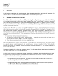
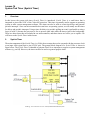
The main component of the Systick Timer is a 24-bit down counter that can be operated with the processor clock
or an input clock signal from a pin (STCLK pin). The general block diagram of a Systick Timer is shown in
figure below. The Systick Timer is intended to generate fixed 10-ms interrupts to support a system management
software (e.g. an OS). However, the timer can also be used as a general purpose timer.
From Fig. 118 in the LPC17xx User manual, NXP Semiconductors, 2010.
1
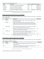
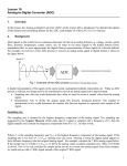
The can be controlled using four registers:
From Table 438 in the LPC17xx User manual, NXP Semiconductors, 2010.
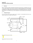
Systick Control and Status Register (STCTRL @ 0xE000E010)
The STCTRL register contains control information for the System Tick Timer, and provides a status flag as
shown in table below.
From Table 439 in the LPC17xx User manual, NXP Semiconductors, 2010.
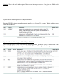
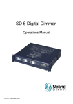
Systick Reload Value Register (STRELOAD @ 0xE000E014)
The value in this register is loaded into the counter whenever the count reaches zero. This value should be
initialized before enabling the interrupt.
From Table 440 in the LPC17xx User manual, NXP Semiconductors, 2010.
Question: What is the maximum value for this register?
0xFFFFFF = 224 – 1 = 16,777,215
2
Question: What is the value in the register if the recurrent interrupt occurs every 1ms given the 10MHz clock
source?
The number of clock cycles required:
1𝑚𝑚𝑚𝑚 1𝑚𝑚𝑚𝑚
10−3
=
=
= 10,000 𝑐𝑐𝑐𝑐𝑐𝑐𝑐𝑐𝑐𝑐𝑐𝑐
1
1
𝑇𝑇
�𝐹𝐹 � �10,000,000�
So, the RELOAD register should have 10,000 -1 = 9,999 (count 0 is 1 cycle).
Systick Current Value Register (STCURR@ 0xE000E018)
Reading STCURR register returns the current count from the System Tick counter. Writing to this register
clears the current count.
From Table 441 in the LPC17xx User manual, NXP Semiconductors, 2010.
Systick Calibration Value Register (STCALIB@ 0xE000E01C)
The STCALIB register contains a pre-defined value for generating an interrupt every 10 milliseconds if the
System Tick Timer is clocked at a frequency of 100 MHz. The use of this register is not required.
From Table 442 in the LPC17xx User manual, NXP Semiconductors, 2010.
3
3.
Example
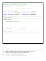
Write a C code to configure the Systick Timer interrupt that should occur every 1 ms. Assume that the processor
clock frequency is 100 MHz.
Tasks:
•
Systick Timer Setup
o Disable System Tick timer. This step is optional but recommended.
o Initialize the reload value.
o Clear the current count.
o Enable the timer interrupt.
o Select the clock source.
o Enable System Tick timer.
•
ISR
o Processing: do nothing in this example
o Clear the flag
Question: what is the name of the ISR for Systick Timer? How would you declare this ISR in C?
The predefined ISR name for the Systick Timer is provided in the startupLPC17xx.s file (see
lesson 11).
Declaration in C:
void SysTick_Handler(void);
4
/*---------------------------------------------------------------------------Lesson 13: using c and Systick timer interrupt
*---------------------------------------------------------------------------*/
#include "LPC17xx.h"
// Device header
void SysTick_Handler(void); // Systick handler declaration
// Define pointers to registers
volatile unsigned int* STCTRL_ptr
= (unsigned int *) 0xE000E010;
volatile unsigned int* STRELOAD_ptr = (unsigned int *) 0xE000E014;
volatile unsigned int* STCURR_ptr
= (unsigned int *) 0xE000E018;
/*---------------------------------------------------------------------------Main: Initialize
*---------------------------------------------------------------------------*/
int main (void) {
/*Initialize Systick Timer
*(STCTRL_ptr)
= 0x0;
*(STRELOAD_ptr) = 99999;
*(STCURR_ptr)
= 0x0;
*(STCTRL_ptr)
= 0x7;
*/
//
//
//
//
while (1){}
// main loop
Disable timer
100,000 cycles = 1ms (100 MHz)
Write anything to this register to clear
ENABLE = 1, TICKINT = 1, CLKSOURCE = 1
}
/*---------------------------------------------------------------------------Systick Timer ISR
*---------------------------------------------------------------------------*/
void SysTick_Handler(void){
/* Processing */
// do nothing;
}
/* clear the flag */
*(STCTRL_ptr);
// Read STCTRL to clear
Exercise: Write a C program to for the example above. Use the simulator to verify 1ms interrupts.
4.
References
[1].
[2].
[3].
[4].
[5].
Joseph Yiu, The Definitive Guide to ARM Cortex-M3 and Cortex-M4 Processors, Elsevier, 3rd ed, 2014.
Jonathan Valvano, Introduction to ARM Cortex-M Microcontroller, 4nd ed, 2013.
ARMv7-M Architecture Reference Manual, ARM Limited, 2010.
LPC17xx User manual, NXP Semiconductors, 2010.
Cortex-M3 Technical Reference Manual, ARM Limited, 2010.
5