1
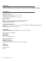
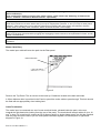
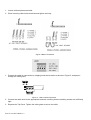
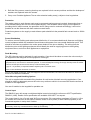
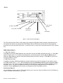
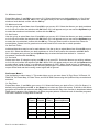
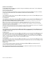
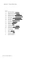
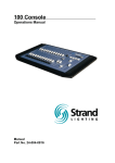
SD 6 Digital Dimmer
Operations Manual
Part No. 24-004-0400 Rev 2
Strand Lighting Limited
Mitchelson Industrial Estate
Kirkcaldy, Fife
United Kingdom
The material in this document is for information purposes only and is subject to change without notice.
Strand Lighting assumes no responsibility for any errors or omissions which may appear in this manual. For
comments and suggestions regarding corrections and/or updates to this manual, please contact your
nearest Strand Lighting office.
El contenido de este manual es solamente para información y está sujeto a cambios sin previo aviso.
Strand Lighting no asume responsabilidad por errores o omisiones que puedan aparecer. Cualquier
comentario, sugerencia o corrección con respecto a este manual, favor de dirijirlo a la oficina de Strand
Lighting más cercana.
Der Inhalt dieses Handbuches ist nur für Informationszwecke gedacht, Aenderungen sind vorbehalten.
Strand Lighting uebernimmt keine Verantwortung für Fehler oder Irrtuemer, die in diesem Handbuch
auftreten. Für Bemerkungen und Verbesserungsvorschlaege oder Vorschlaege in Bezug auf Korrekturen
und/oder Aktualisierungen in diesem Handbuch, moechten wir Sie bitten, Kontakt mit der naechsten Strand
Lighting-Niederlassung aufzunehmen.
Le matériel décrit dans ce manuel est pour information seulement et est sujet à changements sans préavis.
La compagnie Strand Lighting n’assume aucune responsibilité sur toute erreur ou ommission inscrite dans
ce manuel. Pour tout commentaire ou suggestion concernant des corrections et/ou les mises à jour de ce
manuel, veuillez contacter le bureau de Strand Lighting le plus proche.
Part No. 24-004-0400 Rev 2
Introduction
Strand Lighting SD6 and dimmer packs are compact, portable dimming units, designed for use in
conjunction with lighting control consoles as part of entertainment or architectural lighting installations.
Specifications
Power Requirements
Voltage: 200 - 260 Volts AC. Frequency: 50 - 60 Hz.
Three phase + Neutral + Earth
SD6 dimmer packs must be Earthed for safety in use.
Dimming Capacity
SD6
Each pack contains six dimmers with one socket outlet per dimmer.
Maximum load 13A per dimmer - total 78A per dimmer pack.
Minimum load 60W per dimmer.
Dimmer Output Connections
SD6 packs are available with a variety of socket outlets to suit different operating conditions and national
standards.
One socket per dimmer is fitted as standard
Control Inputs
USITT DMX512(1990) multiplexed digital control, via 5 pin XLR connector.
Back up link connector
Physical Dimensions (unpacked)
Height: 90 mm.
Width: 485 mm.
Depth: 395 mm.
Weight: 12Kg (approximately)
Environment (Operating)
Temperature: 0°C - 37°C.
Relative humidity: 0% - 90%.
Condensation level: Zero.
SD6 packs are suitable only for use in a dry, internal environment.
Protection
Classification
IP20 (EN60529).
Equipment Class
Class 1.
Part No. 24-004-0400 Rev 2
Installation
WARNING
Hazardous voltages are used in SD6 dimmer packs. Ensure that the mains supply is isolated before opening
the equipment for installation or servicing.
Dimmer packs should be installed and serviced only by suitably qualified personnel.
SD6 Dimmer racks are designed for rack mount installation in a standard 19” (600mm) equipment rack.
In order to enhance the reliability of the dimmers, it is recommended that they are operated within the
following environmental limits:
Temperature: 15°C - 25°C
Relative Humidity: 60% - 80%
Condensation level: Zero
SD6 dimmers are designed such that Earth leakage currents are minimised, allowing their use on mains
power supplies protected by 30mA Residual Current Devices. However, utilising RCD protection in dimming
installations may present problems. The dimmers may emit a slight buzzing noise when in operation. They
should be installed away from areas where such noise would be undesirable.
The physical dimensions of an SD6 dimmer pack are shown in Figure 1.
Figure 1
Mains Power Input Connections
SD 6 dimmer packs require a nominal mains input at 230V 50Hz AC. This supply may be either single or
three phase (star only), depending on the method of connection. In either case separate Neutral and Earth
conductors are required.
WARNING
SD 6 dimmer packs must be Earthed for safety in operation.
Part No. 24-004-0400 Rev 2
In all cases, the Neutral conductor must have the same (or greater) rating, and cross-sectional area, as the
Phase conductor(s).
(Triac and thyristor dimmers operate using ‘phase control’, which renders the ‘balancing’ of loads across
phases - and thus a reduction in Neutral currents - impossible).
SD 6 dimmer packs should be connected to their mains supplies via adequately rated cable, plugs and sockets.
Power input connectors must be rated at 60A (or more) for single phase operation, or 20A (or more) for three phase
operation. These ratings may only be reduced if the devices protecting the mains supply are selected to limit the
current drawn to the rating of the connectors. Racks should be fed from a fused supply.
It is strongly recommended that the mains supply to the dimmers is taken via a local isolating switch, so that the
supply may be easily disconnected for plugging and unplugging of load connectors, the replacement of fuses, and for
service or maintenance.
All cables and protection equipment must be selected and installed in accordance with locally prevailing electrical
regulations.
Mains Cable Entry
The mains input cable will enter the pack via the Rear panel.
Mains termination
Figure 2
Remove the Top Panel. This is secured to the base by 6 fasteners located at the back and sides.
A 32mm diameter hole is provided in the Panel to permit the mains cable to pass through. This hole should
be fitted with an appropriately sized cable gland.
Cable Termination
The mains input is connected at a set of screw terminal blocks, situated inside the pack, at the rear,
towards the right hand side (looking from the rear of the pack). The terminals will accept cables of up to 10
mm2 in size. If it is required to connect an SD 6 dimmer pack to a single phase supply, the link bar supplied
with the pack should be used to join the three phase terminals together, as follows (refer to right-hand
diagram in Figure 4):
Part No. 24-004-0400 Rev 2
1. Loosen all three phase terminals..
2. Place incoming cable inside terminals and tighten securely.
Figure 4 Mains Termination
1. Prepare the cable for connection by stripping back the insulation as shown in Figure 5, and pass it
through the cable gland.
Figure 5. - Mains Cable Preparation
2. Connect the cable ends to the appropriate terminals, ensuring that the retaining screws are sufficiently
tight.
3. Replace the Top Panel. Tighten the cable gland to secure the cable.
Part No. 24-004-0400 Rev 2
4. Refit the fixing screws, ensuring that they are replaced in their correct positions and that the shakeproof
washers are replaced under the screws.
5. Carry out a Portable Appliance Test or other electrical safety test(s), subject to local regulations.
Protection
The mains supply to each dimmer pack must be protected against external overload. Appropriate fuse or
circuit breaker ratings are 20A for a three phase supply. If the available mains supply is not capable of
providing the full rated currents, the protection device rating must be reduced accordingly; it will not be
possible to use the dimmers with their maximum rated loads.
Protection systems on the supply to each dimmer pack should limit the potential fault current level to 1500A
or less.
Power Distribution
To achieve correct Earthing and mains power distribution, it is recommended that all dimmers and lighting
control equipment within the installation should draw mains power from one central distribution point. This
should be as close as possible to the mains power intake for the site or building. The wiring from the
distribution point to the lighting equipment should ideally be used for supplying power to that lighting
equipment alone, and not to other appliances or equipment.
Rack Mounting
The SD 6 dimmer pack is designed for rack mounting. Care should be taken to mount the unit securely in
an equipment rack designed to hold equipment of this type.
To prevent overheating of rack-mounted dimmers when in use, a fan, or set of fans, should be fitted to the top of the
equipment rack, such that air is extracted upwards. To ensure adequate cooling, the fan(s) should provide an airflow
of about 16 litres per second across the top of each dimmer pack.
A gap of 1 U (44.5mm) is required between adjacent pairs of dimmer racks.
Leave a rear ventilation clearance of 100mm.
Due to the weight of the unit, rack side supports are recommended, but care must be taken to ensure that
these do not obstruct ventilation.
Other Mounting and Handling Options
The unit is supplied with removable fixing brackets for rack/under side/wall mounting applications. Care
should be taken to adequately secure the unit to any surface to which it is mounted and that the surface is
suitable for this application.
One set of handles is also supplied for portable use.
Control Input
The DMX512 input will accept a multiplexed digital control signal which conforms to USITT specification
DMX512 (1990). Details of this specification are available from USITT on request.
The control input is via a five-pin male XLR type connector. Pin connections are shown in Figure 9. A fivepin female XLR connector is also fitted to allow a series of SD 6 packs (or other DMX equipment) to be
connected together in ‘daisy chain’ fashion.
It is recommended that Control connections are not plugged or unplugged when power is applied to the dimmer pack
as this may cause any connected loads to flash up momentarily.
Part No. 24-004-0400 Rev 2
Figure 9
Dimmer Outputs
Dimmer output connections are by means of socket outlets on all styles of SD 6 dimmer packs, except the
terminal strip version. One socket is fitted per dimmer.
When operating from a three phase supply, dimmers 1 and 2 are connected to phase 1, dimmers 3 and 4 to
phase 2, and dimmers 5 and 6 to phase 3.
Plug tops used for dimmer output connections must be of the correct type to match the socket outlets.
It is important that plugs are wired correctly. Figure 10 shows the various types of socket outlets fitted to SD
6 dimmer packs.
Figure 10
Service and Maintenance
SD 6 dimmer packs do not require routine maintenance other than external cleaning. However, in common
with all electrical equipment, they should be periodically checked to ensure that they remain in good
condition. Any repairs or maintenance to the internal electronics, or other circuitry, should be carried out
only by authorised Strand Lighting Service personnel or approved Service Providers.
Part No. 24-004-0400 Rev 2
Safety Tests
SD 6 dimmer packs are subjected to safety inspections and tests prior to despatch from the Strand Lighting
factory.
If, as part of routine checks, the packs are to be subjected to electrical safety tests applied using a
‘standard’ Portable Appliance Tester, the following points should be observed:
The nature of the electronic dimmer circuits means that an ‘insulation test’ using a voltage in the order of
500V will give a result of approximately 1.7MΩ. Although this may appear as a test failure, the apparently
low resistance is normal for an SD 6 dimmer pack and is not due to failing insulation. User safety is not at
risk.
(Any reading below 1.5MΩ indicates a problem which must be investigated).
Caution
A high voltage ‘Flash’ test must not be applied to an SD 6 dimmer pack.
A high current Earth continuity test must not be applied to the signal ground pins of the control input
connector(s).
Part No. 24-004-0400 Rev 2
Set up
Active dimmer
indicator
“Up” Menu select key
“Down” Menu select Key
OK confirms
Commands
Escape
key exits
and menu
LCD Display
Figure 11 Set up keys and displays
The SD 6 dimmer pack offers a wide range of set up and configuration features which accessed from the
front panel with its four set up keys and LCD Display. Menu selections are made with the Up and Down
keys and are confirmed with the OK key. To exit any menu or cancel any commands press the ESC escape
key.
DMX Address Menu 1
11 DMX Start Address
Press Up to access the DMX address menu and OK to access the DMX start address menu 11. Press OK
again to select menu 111 to edit the start address for your dimmer pack. Use the Up and Down keys to
select the DMX address required. Note that holding the key will scroll numbers. Press OK to confirm your
selection or Esc to cancel.
12 DMX Dimmer Patch
In addition to setting a DMX start address a specific address may also be assigned to any dimmer using
any DMX address from 1 – 512. Select the Up key and press OK and the Up Key again followed by OK to
go to menu 121. You can now select any dimmer number between 1 and 6 and confirm with OK or cancel
with Esc. Menu 1211 will now appear and allow you to select any DMX address for the dimmer you
selected. Use the Up/Down keys to make your assignment and Press OK to confirm.
Set Channel Menu 2
Use the Up key to select menu 2. This mode allows you to set menu items 21 Minimum level, 22 Maximum
output, 23 Fade Curves and 24 Fade Time.
Part No. 24-004-0400 Rev 2
21 Minimum Levels
Select Menu item 21 and OK to go to menu 211. Select the dimmer you wish to address or A for All and
confirm the selection with OK. Menu 2111 will appear and you can use the Up/Down keys to select the
minimum level desired, confirm with the OK key.
22 Maximum Levels
Use the up key to select Menu item 22 and OK to go to menu 221. Select the dimmer you wish to address
or A for All and confirm the selection with OK. Menu 2211 will appear and you can use the Up/Down keys
to select the maximum level desired, confirm with the OK key.
23 Set Curves
Use the up key to select Menu item 23 and OK to go to menu 231. Select the dimmer you wish to address
or A for All and confirm the selection with OK. Menu 2311 will appear and you can use the Up/Down keys
to select the curve desired, confirm with the OK key. There are three curves to choose from Linear for
normal fades, Square Law for great low level control and N-D for non dim or switch operation.
24 Set Fade Times
Individual fade times may be set for each dimmer. Use the up key to select Menu item 24 and OK to go to
menu 241. Select the dimmer you wish to address or A for All and confirm the selection with OK. Menu
2411 will appear and you can use the Up/Down keys to select the fade time desired in .1 second
increments, confirm with the OK key.
25 Set Level
Select menu item 25 using the up key and OK to go to menu 251. Select the dimmer you wish to address
or A for All and confirm the selection with OK. Menu 2511 will appear and you can use the Up/Down keys
to select either “equal to input” or a defined level between 0-100%. When “equal to input” is selected the
dimmer(s) level will be controlled by the incoming DMX signal. If a defined level is selected, the dimmer(s)
output will be fixed and the incoming control signal will be ignored.
Set Scenes Menu 3
Use the Up key to select menu 3. This mode allows you to set menu items 31 Play Show, 32 Record, 33
DMX Fail, 34 Preset Map, 35 Fade Times, and 36 No DMX Scene using the Up/Down Keys to make each
selection.
31 Play Show
Select Menu item 31 and OK to go to menu 311. Select the Scene you wish to Run (1-24) (Go Scene 1 is
default) using the Up key and OK, or the Down key to select any of the 24 scenes, 10 shows or 90 effects
programs and confirm the selection with OK. Please note that the Play show function is deactivated when a
DMX signal is present. See Appendix 1 for Effect program patterns. Note that each of the effect programs
can have a selection of step times as follows:
Part No. 24-004-0400 Rev 2
Effect
Time #
Time in
Seconds
Effect
Time #
Time in
Seconds/Minutes
1
.2
6
5
2
.4
7
10
3
1
8
2 mins
4
1.5
9
5 mins
5
2
10
10 mins
32 Record
You may record Back up scenes using this menu and a DMX consoles. First set the desired levels using
your console. Next Select Menu item 32 and OK to go to menu 321. Select the scene number you wish to
record to using the Up key. Use the Down key to select clear all scenes and OK to confirm.
33 DMX Fail
Use this mode to select what action the dimmer pack should follow on loss of DMX. Select Menu item 33
and OK to go to menu 331. Press Up to select All Off to have the dimmers fade to black on mux fail. Press
Up again to hold the last levels or again to choose a specific scene 24. The next Up selection is Go No
DMX to select the No DMX Scene (Set in Menu item 36) and finally Go B. L. to select the Back up Link
input (please refer to appendix 2 for Back Up Link application example).
34 Preset B.L. (Back Up Link)
Use this to select the preferred play back for each channel in back up mode. Up to 24 channels can be set.
Select Menu item 34 and OK to go to menu 341. Use the Up/Down keys to select the channel number and
confirm with OK to go to menu 3411. Use the Up/Down keys to select any of the 24 scenes, 10 shows or
90 programs and confirm the selection with OK.
(Note: to use the back up link function when DMX fail, please ensure "B.L." is selected in 33 DMX fail
menu.)
35 Fade Times
This menu is used to set the fade time for a selected scene, show or program in play show or back up
mode. Select Menu item 35 and OK to go to menu 351. Use the Up/Down keys to select the desired
Scene or A for All followed by OK to go menu 3511 to set the time. You can use the Up/Down keys to
select the fade time desired in .1 second increments, confirm with the OK key.
36 No DMX Scene
Select Menu item 36 and OK to go to menu 361. Use the Up/Down keys to change the desired Scene
followed by OK to confirm your selection.
Test Channels Menu 4
Use the Up key to select menu 4 and press OK to go to menu 41. This mode allows users to turn dimmers
on locally to test dimmer output. Use the Up/Down keys to select the desired dimmer or A for all. Press OK
once to turn dimmer(s) on to Full, Press twice for half and three times for Off. Use Esc to cancel.
Input Menu 5
This menu allows you to select between DMX control and the B. L. (Back up link) only. Use the Up key to
select menu 5 and press OK to menu go to 51. Use the Up/Down keys to select the input source and OK
to confirm.
Note that when B.L. Only is selected, DMX signal input to the "DMX IN" does not work.
Unit Set up Menu 6
This menu allows you to set up the unit as a Master or Slave. Use the Up key to select menu 6 and press
OK to go to menu 61. Use the Up/Down keys to make a selection and OK to confirm or ESC to cancel.
When the unit is set as master, "DMX out" will pass through the normal DMX signal as well as control signal
from back up. When set as slave, only normal DMX will be looped through.
Part No. 24-004-0400 Rev 2
Software Version Menu 7
To see which version of software your system is using use the Up key to select menu 7 and to display the
current software on your system
Read Information Menu 8
This menu will allow you to Read Hours use (81) Temperature settings (82), DMX Levels (83), Lock Menu
Access (84) and Set Defaults (85). Use the Up key to select menu 8 and press OK.
81 Read Hours
Use the Up key to select menu 8 and press OK and the Up key to go to menu 81. Select OK again to go to
menu 811 for total running hours.
82 Temperature
Use the Up key to select menu 8 and press OK and the Up Key to go to menu 82. Select OK again to go to
menu 821 to see the Max temperature, Minimum Temperature and Present Temperature of the dimmer
pack. Select Reset and OK to reset all temperature data.
Note: If the maximum operating temperature exceeds 70 degrees Celsius the system will reduce all
dimmer levels to 50% output and display an OVER TEMPERATURE message. You may use the Reset
command to return to normal operation.
When the recorded temperature exceeds 70 degrees and the ambient temperature is also over 70 degrees
the system cannot be reset until the over temperature condition is corrected.
83 DMX levels
Use the Up key to select menu 8 and press OK and the Up Key to go to menu 83. Select OK again to go to
menu 831 to see the current DMX value for each dimmer. Use the Up/Down keys to look at each dimmer.
Use ESC to exit this menu.
84 Menu Access
Use the Up key to select menu 8 and press OK and the Up Key to go to menu 84. Select OK again to go to
menu 841 to Lock Menu access using the Up/Down keys to select “lock” and OK to confirm and ESC to
cancel. To Unlock, go to menu 841 again, press and hold Up key for 5 seconds and then press Down key
while still holding the Up key. Select “unlock” and press OK to confirm.
85 Set Defaults
Use the Up key to select menu 8 and press OK and the Up Key to go to menu 85. Select OK again to reset
all systems to default start mode. The System will ask you to confirm with an Are You Sure message. Press
OK to confirm and ESC to cancel.
Keypad Lock
You can lock the system keypad by pressing and holding the OK and ESC keys simultaneously for 3
seconds. Repeat the process to unlock the keypad.
Note: The keypad will also lock itself out automatically if no selection is made for more than 10 minutes.
The keypad may be unlocked with the same procedure.
Part No. 24-004-0400 Rev 2
Appendix 1 – Effect Program Patterns
Step
PROG: 1-10
Channel
I II III IV
I
II
III
IV
V
VI
Step
1
0
0
0
0
0
0
1
0
0
0
0
0
0
1
0
0
0
0
0
0
1
0
0
PROG: 11-20
Channel
I II III IV
I
II
III
IV
V
VI
1
0
0
0
0
1
1
1
0
0
0
0
0
1
1
0
0
0
0
0
1
1
0
0
V
VI
0
0
0
0
1
0
0
0
0
0
0
1
V
VI
0
0
0
1
1
0
0
0
0
0
1
1
Step
Step
I
II
III
IV
1
0
0
0
0
1
0
1
0
0
1
0
0
0
1
0
V
VI
0
1
0
1
1
0
0
0
V
VI
1
1
1
1
0
0
0
1
1
1
1
0
0
0
1
1
1
1
III IV
V
VI
1
0
0
1
0
1
V
VI
0
1
1
1
1
1
0
1
0
1
1
1
PROG: 71-80
Channel
I II III IV
V
VI
1
0
1
0
1
0
PROG: 81-90
Channel
I II III IV
V
VI
0
0
0
0
0
0
0
0
1
0
0
0
0
0
0
0
0
0
0
0
0
0
1
0
I
II
III
IV
V
VI
Step
I
II
Step
PROG: 31-40
Channel
I II III IV
I
II
III
IV
V
VI
VII
VIII
1
0
0
0
0
0
0
0
1
1
0
0
0
0
0
1
Part No. 24-004-0400 Rev 2
0
1
1
0
0
0
1
1
0
0
1
1
0
1
1
0
V
VI
0
0
0
1
1
1
0
0
0
0
0
0
1
0
0
0
Step
1
1
0
0
1
1
1
0
1
0
1
1
1
0
0
1
0
1
PROG: 61-70
Channel
I II III IV
I
II
III
IV
Step
1
0
0
1
1
1
PROG: 51-60
Channel
I II
I
II
Step
PROG: 21-30
Channel
I II III IV
PROG: 41-50
Channel
I II III IV
I
II
III
IV
V
VI
VII
VIII
IX
X
XI
XII
1
1
0
1
1
0
1
0
0
0
0
0
0
0
0
0
0
0
0
1
1
1
1
0
0
0
1
0
0
0
0
0
0
0
0
0
1
1
0
1
1
0
0
0
0
0
1
0
0
0
0
0
0
0
0
0
0
0
0
0
1
0
0
0
0
0
Appendix 2 – Back Up Link
Application example Control SD6’s in array format
Unit Setup (menu 6)
Input (menu 5)
DMX in port
Backuplink port
DMX fail (menu 33)
1st pack
Master
B.L. only
Disable
Enable
Don't care
2nd pack
Slave
DMX only
Enable
Disable
Don't care
n th pack
Slave
DMX only
Enable
Disable
Don't care
As scenes backup when main
DMX failed
1st pack 2nd pack
n th pack
Master
Slave
Slave
DMX only DMX only DMX only
Enable
Enable
Enable
Enable
Disable
Disable
B.L.
Don't care Don't care
activated
Note :
1.
2.
3.
4.
Back up link will be triggered on when input level is more than 30%.
Back Up Link will be triggered off when level is less than 3%.
Triggering priority from Channel 1 (highest) to Channel 24 (lowest).
If back up scenes are to be used, please ensure back up scenes are recorded using “Record” (Menu 32)
prior to running the Back Up Link.
Typical Multi packs connection using backuplink as backup to main
Part No. 24-004-0400 Rev 2
Appendix 3 – Factory Default Value
Menu :
11
MX Start Address – Channel 1
12
DMX Dimmer Patch – Channel 1
21
Minimum Levels – 0% (All Channels)
22
Maximum Levels – 100% (All Channels)
23
Set Curves – Square (All Channels)
24
Set Fade Times – 0 sec (All Channels)
25
Set Level – Input (All Channels)
31
Play Show – Go Scene 1
32
Record – Get Scene 1
33
DMX Fail – All off
34
Preset Backuplink – Channel 1
35
Fade Time – 0 sec (All Scenes)
36
No DMX Scene – Do Scene 1
4
Test Channel –
5
Input – DMX only
6
Unit Setup – Slave
7
Software Version –
8
Read Information –
Part No. 24-004-0400 Rev 2
Berlin
Strand Lighting GMBH
Ullsteinstrasse. 114-142, HAUS C
D-12109
Berlin, Germany
Tel. +49-30-707-9510
Fax +49-30-707-95199
Hong Kong
Strand Lighting Asia LTD
20/F., Delta House
3 On Yiu Street
Shatin, N.T.
Hong Kong
Tel. +852-2757-3033
Fax +852-2757-1767
London
Strand Lighting Limited
Unit 3 Hammersmith Studios
Yeldham Road
Hammersmith
London, England W6 8JF
Tel. +44-20-8735-9790
Fax +44-20-8735-9799
Rome
Strand Lighting Italia
Via Delle Gardenie S.N.C.
Pontina Vecchia KM 33,400
00040 Pomezia
Italy
Tel. +39-0691-9631
Fax +39-0691-47138
Part No. 24-004-0400 Rev 2