1
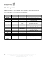
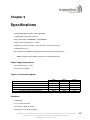
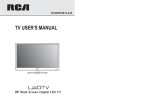
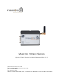
M AESTRO 100 EVO S ERIES
Q UICK S TART G UIDE & U SER M ANUAL R EV. 0.2
WWW. MAESTRO - WIRELESS . COM
E MAIL : CONTACT @ MAESTRO - WIRELESS . COM
T EL : 852 2869 0688
FAX : 852 2525 4701
A DDRESS : R OOM 3603-3609, 36/F, 118 C ONNAUGHT R OAD W EST, S HEUNG WAN , H ONG KONG
2
Confidential, the whole document is the sole property of Maestro Wireless Solutions ltd.
3603-9, 36/F., 118 Connaught Road West, Sheung Wan, Hong Kong
[email protected]
Revision history
Rev.
0.1
0.2
Date
11 August 2010
25 August 2010
Details
First release
Proof reading
Originated by
Samuel Chereau
Pierre-Emmanuel Surga
This manual is written without any warranty.
Maestro Wireless Solutions Ltd. reserves the right to modify or improve the product and its accessories
which can also be withdrawn without prior notice.
Besides, our company stresses the fact that the performance of the product as well as accessories depends
not only on the proper conditions of use, but also on the environment around the places of use.
Maestro Wireless Solutions Ltd. assumes no liability for damage incurred directly or indirectly from
errors, omissions or discrepancies between the modem and the manual.
This software, solution or application is provided on an "as is" basis. No warranty whether expressed or
implied is given by Maestro Wireless Solutions Ltd. in relation to this software, solution or application.
User shall assume the entire risk of using or relying on this software, solution, application.
In no event will Maestro Wireless Solutions Ltd. be liable for any loss or damage including without
limitation, indirect or consequential loss, damage, or any loss, damage whatsoever arising from loss of
data or profit arising out of, or in connection with, the use of this software, application or solution. Every
effort is made to keep the software, application or solution up and running smoothly. However, Maestro
Wireless Solutions Ltd. takes no responsibility for, and will not be liable for, the software, application or
solution being temporarily unavailable due to technical issues beyond our control.
The above terms and conditions are subject to change without prior notice. The present use of this software, application or solution implies the user approves and understands all the above terms and conditions.
Confidential, the whole document is the sole property of Maestro Wireless Solutions ltd.
3603-9, 36/F., 118 Connaught Road West, Sheung Wan, Hong Kong
[email protected]
3
4
Confidential, the whole document is the sole property of Maestro Wireless Solutions ltd.
3603-9, 36/F., 118 Connaught Road West, Sheung Wan, Hong Kong
[email protected]
Contents
1 M100evo easy setup guide
9
1.1 Download the M100evo configuration software . . . . . . . . . . . . . . . . . . . . . . . . . .
9
1.2 Use of the M100evo configuration software . . . . . . . . . . . . . . . . . . . . . . . . . . . .
9
1.2.1 COM port . . . . . . . . . . . . . . . . . . . . . . . . . . . . . . . . . . . . . . . . . . .
9
1.2.2 Modem status . . . . . . . . . . . . . . . . . . . . . . . . . . . . . . . . . . . . . . . . 10
1.2.3 Network and Serial port . . . . . . . . . . . . . . . . . . . . . . . . . . . . . . . . . . . 10
1.2.4 GPRS & TCP/IP connection . . . . . . . . . . . . . . . . . . . . . . . . . . . . . . . . . 11
1.2.5 Call screening . . . . . . . . . . . . . . . . . . . . . . . . . . . . . . . . . . . . . . . . 11
1.2.6 Remote control . . . . . . . . . . . . . . . . . . . . . . . . . . . . . . . . . . . . . . . . 12
1.2.7 IP ping . . . . . . . . . . . . . . . . . . . . . . . . . . . . . . . . . . . . . . . . . . . . . 12
1.2.8 TMODE . . . . . . . . . . . . . . . . . . . . . . . . . . . . . . . . . . . . . . . . . . . . 13
1.2.9 DOTA . . . . . . . . . . . . . . . . . . . . . . . . . . . . . . . . . . . . . . . . . . . . . 13
1.2.10 Trigger I/O
. . . . . . . . . . . . . . . . . . . . . . . . . . . . . . . . . . . . . . . . . . 14
2 Equipments Description
15
2.1 Package . . . . . . . . . . . . . . . . . . . . . . . . . . . . . . . . . . . . . . . . . . . . . . . . 15
2.2 Interfaces . . . . . . . . . . . . . . . . . . . . . . . . . . . . . . . . . . . . . . . . . . . . . . . 15
2.2.1 Status indicator
. . . . . . . . . . . . . . . . . . . . . . . . . . . . . . . . . . . . . . . 15
2.2.2 SMA female antenna connector
. . . . . . . . . . . . . . . . . . . . . . . . . . . . . . 16
2.2.3 15-Pin D-Sub Female connector (RS232/Audio) . . . . . . . . . . . . . . . . . . . . . 16
2.2.4 4-Pin connector (Power input/output) . . . . . . . . . . . . . . . . . . . . . . . . . . . . 17
2.3 Optional accessories . . . . . . . . . . . . . . . . . . . . . . . . . . . . . . . . . . . . . . . . . 17
3 Installation
3.1 Mounting the modem
19
. . . . . . . . . . . . . . . . . . . . . . . . . . . . . . . . . . . . . . . . 19
3.2 Install the SIM card . . . . . . . . . . . . . . . . . . . . . . . . . . . . . . . . . . . . . . . . . . 19
3.3 Connect the external antenna (SMA type) . . . . . . . . . . . . . . . . . . . . . . . . . . . . . 19
3.4 Connect the modem to external device . . . . . . . . . . . . . . . . . . . . . . . . . . . . . . . 20
3.5 Connect the DC power supply . . . . . . . . . . . . . . . . . . . . . . . . . . . . . . . . . . . . 20
Confidential, the whole document is the sole property of Maestro Wireless Solutions ltd.
3603-9, 36/F., 118 Connaught Road West, Sheung Wan, Hong Kong
[email protected]
5
4 Default Settings
21
4.1 Factory settings . . . . . . . . . . . . . . . . . . . . . . . . . . . . . . . . . . . . . . . . . . . . 21
4.2 Input/Output port . . . . . . . . . . . . . . . . . . . . . . . . . . . . . . . . . . . . . . . . . . . 21
4.3 Analog input port . . . . . . . . . . . . . . . . . . . . . . . . . . . . . . . . . . . . . . . . . . . 22
4.4 RS232 Auto-online mode (power saving)
. . . . . . . . . . . . . . . . . . . . . . . . . . . . . 22
5 Troubleshooting
23
5.1 The modem’s LED does not light . . . . . . . . . . . . . . . . . . . . . . . . . . . . . . . . . . 23
5.2 The modem’s LED lights but does not blink long time after power up . . . . . . . . . . . . . . 23
5.3 The modem does not respond to the terminal program
. . . . . . . . . . . . . . . . . . . . . 23
5.4 No voice could be heard for the modem’s speaker output when a call is answered
. . . . . . 23
5.5 Debug, or further command using Microsoft Windows XP Hyper Terminal as example . . . . 24
5.6 Basic operations . . . . . . . . . . . . . . . . . . . . . . . . . . . . . . . . . . . . . . . . . . . 26
6 Specifications
6
Confidential, the whole document is the sole property of Maestro Wireless Solutions ltd.
3603-9, 36/F., 118 Connaught Road West, Sheung Wan, Hong Kong
[email protected]
27
Safety precautions
General precautions
– The modem generates radio frequency (RF) power. When using the modem care must be taken on
safety issues related to RF interference as well as regulations of RF equipment.
– Do not use your phone in aircraft, hospitals, petrol stations or in places where using GSM products is
prohibited.
– Be sure that the modem will not be interfering with nearby equipment. For example: pacemakers or
medical equipment. The antenna of the modem should be away from computers, office equipment,
home appliance, etc.
– An external antenna must be connected to the modem for proper operation. Only used approved
antennas with the modem. Please contact authorized dealer on finding an approved antenna.
– Always keep the antenna with minimum safety distance of 26.6cm or more from human body. Do not
put the antenna inside metallic box, containers, etc.
Using the modem in vehicle
– Check for any regulation or law authorizing the use of GSM in vehicle in your country before installing
the modem
– Install the modem by qualified personnel. Consult your vehicle dealer for any possible interference of
electronic parts by the modem.
– The modem should be connected to the vehicle’s supply system by using a fuse-protected terminal
in the vehicle’s fuse box
– Be careful when the modem is powered by the vehicle’s main battery. The battery may be drained
after extended period.
Protecting your modem
To ensure error-free usage, please install and operate your modem with care. Do remember the following:
– Do not expose the modem to extreme conditions such as high humidity/rain, high temperatures, direct
sunlight, caustic/harsh chemicals, dust, or water.
– Do not try to disassemble or modify the modem. There is no user serviceable part inside and the
warranty would be void.
– Do not drop, hit or shake the modem. Do not use the modem under extreme vibrating condition.
– Do not pull the antenna or power supply cable. Please attach or detach by holding the connector.
– Connect the modem only according to the instruction manual. Failure to do it will void the warranty
Confidential, the whole document is the sole property of Maestro Wireless Solutions ltd.
3603-9, 36/F., 118 Connaught Road West, Sheung Wan, Hong Kong
[email protected]
7
8
Confidential, the whole document is the sole property of Maestro Wireless Solutions ltd.
3603-9, 36/F., 118 Connaught Road West, Sheung Wan, Hong Kong
[email protected]
Chapter 1
M100evo easy setup guide
Maestro 100evo series is a range of ready-to-use GSM modems for voice, data, fax and SMS services. It
also supports GPRS Class 10 for packet mode data transfer. The M100evo is easily controlled by using
AT command for all kinds of operations. Fitted with a standard fifteen pins RS232 port and telephone-like
audio plug (via optional Y-cable) the M100evo can be set up with minimal effort. The M100evo modem also
features a digital input/output pin and an analog input pin.
1.1
Download the M100evo configuration software
Start your web browser and download the M100evo configuration software at this address: http://www.
maestro-wireless.com/software/.
Please extract the .rar file and start the setup.exe application. Follow the instructions on screen to install
the software. It will also create a shortcut on your desktop.
1.2
Use of the M100evo configuration software
Note: For more details on each AT command, parameters and feature of the modem please
refer to the software manual rev. 0.95.
1.2.1
COM port
This window will appear when the application starts, you need to enter your COM port settings. Default
settings are the factory settings of the M100evo.
Confidential, the whole document is the sole property of Maestro Wireless Solutions ltd.
3603-9, 36/F., 118 Connaught Road West, Sheung Wan, Hong Kong
[email protected]
9
1.2.2
Modem status
After an automatic serial connection check, the Modem Status tab will appear. It displays the reception
signal strength (RSSI, refreshed every five seconds), your SIM card network name, as well as the revision
number for the embedded application and firmware.
1.2.3
Network and Serial port
In this second tab you can change all the settings of the serial port, and GSM network bands..
Note: To reboot your modem just unplug the power supply cable, and plug it back.
Note: After changing your serial port settings you will have to restart the configuration software
with the new COM interface parameters.
10
Confidential, the whole document is the sole property of Maestro Wireless Solutions ltd.
3603-9, 36/F., 118 Connaught Road West, Sheung Wan, Hong Kong
[email protected]
1.2.4
GPRS & TCP/IP connection
In this tab you will be able to setup most of the GPRS-related features of the SmartPackII. The most
important is the APN (access point name, which is provided by your network operator). For more details on
each features please refer to the SmartPackII software manual. This tab is also used to setup automatic
TCP/UDP connection to a remote server, or as a server.
Note: All the other values in here are default values.
1.2.5
Call screening
This tab lets you set the call screening settings, which allows you to filter the incoming call to your modem
up to 10 phone numbers.
Note: Input the number with + for the country code. Example: +85298635152 for a Hong Kong
number.
Confidential, the whole document is the sole property of Maestro Wireless Solutions ltd.
3603-9, 36/F., 118 Connaught Road West, Sheung Wan, Hong Kong
[email protected]
11
1.2.6
Remote control
This tab allows you to setup your Dynamic DNS account, and the remote access settings for your modem. These functions give you a way to remotely configure and diagnostic your modem, by sending AT
commands over SMS or GPRS (telnet mode).
For more details, please refer to the SmartPackII software manual.
1.2.7
IP ping
This tab allow you to ping an IP address on the Internet, for test and debug purpose. It is designed to give
you a quick way to verify the GPRS data parameters.
12
Confidential, the whole document is the sole property of Maestro Wireless Solutions ltd.
3603-9, 36/F., 118 Connaught Road West, Sheung Wan, Hong Kong
[email protected]
1.2.8
TMODE
This tab is for the SmartPackII Tmode that allow to check your modem ROM, signal strength, IP address
and module input voltage, and send alert by SMS if values exceed a treshold.
1.2.9
DOTA
This tab allow you to setup your FTP server for over the air embedded application update. The actual
update process is triggered by a SMS or an AT command sent remotely (see the remote control tab).
Confidential, the whole document is the sole property of Maestro Wireless Solutions ltd.
3603-9, 36/F., 118 Connaught Road West, Sheung Wan, Hong Kong
[email protected]
13
1.2.10
Trigger I/O
The M100evo features one digital I/O. Using this function, you can have any AT command triggered when
a digital signal is received on this digital input.
14
Confidential, the whole document is the sole property of Maestro Wireless Solutions ltd.
3603-9, 36/F., 118 Connaught Road West, Sheung Wan, Hong Kong
[email protected]
Chapter 2
Equipments Description
2.1
Package
The M100evo package includes the following:
– M100evo modem x 1
– Power cord with fuse x 1
– Safety note x 1
2.2
2.2.1
Interfaces
Status indicator
The LED will indicate different status of the modem:
– OFF: modem is switched off
– ON: modem is connecting to the network
– Flashing slowly: modem is in idle mode
– Flashing rapidly: modem is in transmission/communication (GSM only)
Confidential, the whole document is the sole property of Maestro Wireless Solutions ltd.
3603-9, 36/F., 118 Connaught Road West, Sheung Wan, Hong Kong
[email protected]
15
2.2.2
SMA female antenna connector
Connect this to an external antenna with SMA male connector. Make sure the antenna is for the correct
GSM frequency with impedance of 50 Ohm, and also that the connector is tightly secured.
2.2.3
15-Pin D-Sub Female connector (RS232/Audio)
This connector provides serial link and audio link to the modem.
Pin Number
Name
EIA designation
Type
1
2
3
4
5
6
7
8
9
10
11
12
13
14
15
DCD
TX
BOOT
MICROPHONE +
MICROPHONE RX
DSR
DTR
GND
SPEAKER +
CTS
RTS
RI
RESET
SPEAKER -
Data Carrier Detect
Transmit Data
Output
Input
Input
Input
Input
Output
Output
Input
Ground
Output
Output
Input
Output
Input
Output
Receive Data
Data Set Ready
Data Terminal Ready
Ground
Clear To Send
Request To Send
Ring Indicator
Note
Not used
With 2VDC bias output
With 2VDC bias output
Pull low to reset
Specification of microphone and speaker to be connected:
Parameters
Microphone current @2V/2K Ohm
Microphone input level
Speaker output current 150 Ohm/1nF
Speaker impedance
Min
Typical
Max
0.5mA
100mVpp
32 Ohm
16mA
50 Ohm
Please refer to the document "Application notes - Power supply & Audio" for more information about audio
connection.
16
Confidential, the whole document is the sole property of Maestro Wireless Solutions ltd.
3603-9, 36/F., 118 Connaught Road West, Sheung Wan, Hong Kong
[email protected]
2.2.4
4-Pin connector (Power input/output)
A cable, included in the package shall be used for power supply connection:
Pin assignment of 4-Pin connector:
Pin number
Name
Functions
1
2
3
4
ADC
GPIO
POWER POWER +
Analog input
General purpose I/O
DC power negative input (or ground)
DC power positive input
The power cable included in the package shall be used for power supply connection:
2.3
Optional accessories
You may contact your sales agent for the following optional accessories:
External antenna
– Magnetic mount type
– Frequency GSM 900/1800 band
– Gain 3db
– VSWR < 1.5:1
– Height ~ 236 mm (including magnetic base)
– Cable: Type RG-174U length 2.5m
Confidential, the whole document is the sole property of Maestro Wireless Solutions ltd.
3603-9, 36/F., 118 Connaught Road West, Sheung Wan, Hong Kong
[email protected]
17
‘Y’ cable
– Direct connection with standard 9-pin RS-232
port (DTE)
– Direct connection with common handset of
telephone for voice call
– Shielded cable
– Cable length 1.1m (w/connector)
Sub-D 9 pin
4p4c plug
Pin assignment:
Sub-D 15 (male)
Sub-D 9 (female)
1
2
3
4
5
6
7
8
9
10
11
12
13
14
15
1
3
Plug 4P4C
1
4
2
6
4
5
2
8
7
9
3
DIN rail mount
– Quick attachment / detachment to standard
35mm DIN rail
– Zinc plated steel
18
Confidential, the whole document is the sole property of Maestro Wireless Solutions ltd.
3603-9, 36/F., 118 Connaught Road West, Sheung Wan, Hong Kong
[email protected]
Chapter 3
Installation
3.1
Mounting the modem
Use 2 pieces of M3 screw to mount the modem on the DIN rail mount.mount if you are using it. Please
refer to document "Installation of DIN rail mount" for details.
3.2
Install the SIM card
Use a ball pen or paper clip to press the SIM holder eject button. The SIM holder will come out a little.
Then take out the SIM holder.
Note: DO NOT pull out the SIM holder without pushing the ejector button.
Put the SIM card to the tray; make sure it has completely sat on the tray. Put back the tray into the slot.
3.3
Connect the external antenna (SMA type)
Connect this to an external antenna with SMA male connector. Make sure the antenna is for the GSM
frequency with impedance of 50 Ohm, and also connector is secured tightly.
Note: Please use antenna designed for GSM device operation. Incorrect antenna will affect
communication and even damage the modem.
Note: Please respect a safety distance of at least 26.6cm to the antenna during the modem
operation.
^DŵĂůĞĐŽŶŶĞĐƚŽƌŽĨ
ĂŶƚĞŶŶĂĐĂďůĞ
^ĞĐƵƌĞƚŝŐŚƚůLJ
Confidential, the whole document is the sole property of Maestro Wireless Solutions ltd.
3603-9, 36/F., 118 Connaught Road West, Sheung Wan, Hong Kong
[email protected]
19
3.4
Connect the modem to external device
You can use the optional ’Y’ cable to connect the modem’s Sub-D connector to external controller/computer,
or use the DB15 to DB9 convertion dongle provided by Maestro.
Note: The modem CANNOT be directly connected to the ’LINE’ jack of a land-line telephone.
It is not a foreign exchange station.
Connection example using optional ’Y’ cable:
ϰƉϰĐƉůƵŐ
,ĂŶĚƐĞƚŽĨƉŚŽŶĞ
DĂĞƐƚƌŽϭϬϬ
^ƵďͲϭϱƉŝŶ
ĐŽŶŶĞĐƚŽƌ
Ͳϵ
ĐŽŶŶĞĐƚŽƌ
Z^ͲϮϯϮƉŽƌƚŽĨW
3.5
Connect the DC power supply
Connect the open ending of the provided power cord to a DC supply. Refer to the following for power supply
requirement:
– Input voltage range : 5-32V
– Rated current: 650mA
AC-DC Adaptor
or battery
(Not included)
Solder wire
endings
Plug the molex ending of the power cable to the modem DC connector.
The modem will turn on automatically. The status indicator on the modem will be lit when power on. After
a few seconds it will go flashing slowly (registered to the network successfully refer 1.2.1)
20
Confidential, the whole document is the sole property of Maestro Wireless Solutions ltd.
3603-9, 36/F., 118 Connaught Road West, Sheung Wan, Hong Kong
[email protected]
Chapter 4
Default Settings
4.1
Factory settings
The modem has the following factory settings. Please refer to the AT command document for the meaning
of each setting.
Related AT commands
Factory settings
Description
AT+IPR
AT+IFC
AT+ICF
ATE
AT&C
AT&D
ATQ
ATV
AT&S
ATS0
AT+CLIP
AT+CRLP
AT+CSCS
AT+CMGF
AT+CSMP
AT+CNMI
115200
2,2
3,4
1
1
2
0
1
1
0
0
DTE-DCE data rate
DTE-DCE flow control
DTE-DCE character framing
ECHO
DCD signal
DTR signal
Result code suppression
Response format
DSR signal
Auto answer
Calling line ID presentation
Calling line ID restriction
Character Set
Short message format
Test mode parameters*
New message indication*
“PCCP437”
1
1,67,0,0
0,1,0,0
*Note: settings stored in SIM, not in modem
4.2
Input/Output port
This port can be configured as either an input one or an output one.
The port is mapped to GPIO26 on the internal micro-controller.
To setup this port as an input, type AT+WIOM=1,"GPIO26",0 on the serial port. Then you can read the
status of the input with AT+WIOR="GPIO05". +WIOR: 0 means 0V while +WIOR: 1 means a positive
voltage of no more than 2.8V. Higher voltages may damage the M100evo.
To setup this port as an output, type AT+WIOM=1,"GPIO26",1 on the serial port. Then you can set the
status of the output with AT+WIOW="GPIO26",0 for 0V, AT+WIOW="GPIO26",1 for 2.8V.
Confidential, the whole document is the sole property of Maestro Wireless Solutions ltd.
3603-9, 36/F., 118 Connaught Road West, Sheung Wan, Hong Kong
[email protected]
21
4.3
Analog input port
This port can be used either as a voltage input (0-5V range) or as a current input (0-20mA range). To setup
the port as a voltage input, issue the following commands: AT+WIOM=1,"GPIO19",1 then AT+WIOW="GPIO19",0.
For a current input, issue: AT+WIOM=1,"GPIO19",1 then AT+WIOW="GPIO19",1.
To read the value of the input, use the command AT+ADC?. More information can be found in the AT
commands interface guide document.
4.4
RS232 Auto-online mode (power saving)
When being in the auto-online, the RS232 transceiver will shut down most of its hardware to save power is
it does not detect a valid input for more than 100uS. The RS232 transceiver will wake up when valid input
is detected again.
By default, the RS232 transceiver is put in auto-online. This mode can be turned off by issuing AT+WIOM=1,"GPIO25",1
then AT+WIOW="GPIO26",1.
22
Confidential, the whole document is the sole property of Maestro Wireless Solutions ltd.
3603-9, 36/F., 118 Connaught Road West, Sheung Wan, Hong Kong
[email protected]
Chapter 5
Troubleshooting
5.1
The modem’s LED does not light
– Check if the modem has been properly connected to a 5-32V power supply
– Check if the power connector is properly inserted
– Check the fuse on the power cord
5.2
The modem’s LED lights but does not blink long time after power
up
– Check if a valid SIM card has been properly inserted
– Check if the SIM card has been locked (refer to AT+CPIN command in AT command guide)
– Check if the external has been properly connected to the modem
– Check if the network coverage is available
5.3
The modem does not respond to the terminal program
– Check if the RS232 cable has been properly connected
– Check if your program has proper settings. Factory setting of the modem is:
• 115200 bps
• 8 data bits
• No parity bit
• 1 stop bit 4.
5.4
No voice could be heard for the modem’s speaker output when
a call is answered
– Make sure a voice call has been made (refer to AT command guide)
– Enter the AR+SPEAKER=1 command
Confidential, the whole document is the sole property of Maestro Wireless Solutions ltd.
3603-9, 36/F., 118 Connaught Road West, Sheung Wan, Hong Kong
[email protected]
23
5.5
Debug, or further command using Microsoft Windows XP Hyper
Terminal as example
1. On the first time power-up you can use terminal software to communicate with the modem through
an RS232 serial port. Following example is using the Hyper Terminal in Windows XP.
2.
3. On Windows XP, start the Hyper Terminal program. Assign a name for a new session.
4.
5. Choose the correct Com port and baud rate settings (115200bps, 8bits, no parity bit, 1 stop bit)
6.
24
Confidential, the whole document is the sole property of Maestro Wireless Solutions ltd.
3603-9, 36/F., 118 Connaught Road West, Sheung Wan, Hong Kong
[email protected]
7. On the terminal screen, type "AT" to check the "OK" response from the modem
8.
Confidential, the whole document is the sole property of Maestro Wireless Solutions ltd.
3603-9, 36/F., 118 Connaught Road West, Sheung Wan, Hong Kong
[email protected]
25
5.6
Basic operations
Followings are examples of some AT commands. Please refer to the AT command document for a full
description.
Note: Issue AT+CMEE=1 to have extended error code (+CME ERROR)
Description
AT commands
Modem response
Network
registration
checking
AT+CREG?
CREG=<mode>,1
Modem registered to the network
CREG=<mode>,2
Registration lost, re-registration attempt
Modem not registered on the network, no
registration attempt
The first parameter has to be at least 15 for
normal communication
CREG=<mode>,0
Receiving signal
strength
Receiving an
incoming call
Make a call
AT+CSQ
+CSQ:20,0
RING
An incoming call is waiting
ATA
OK
ATD1234567;
OK
Answer the call
Communication established (Don’t forget the
“;” at the end for “voice” call)
PIN code not entered (with +CME=1 mode)
AOC credit exceeded or a communication is
already established
Communication established (Don’t forget the
“;” at the end for “voice” call)
+CME ERROR: 11
+CME ERROR: 3
Make an
emergency call
Communication
loss
Hang up
Enter PIN code
Saves parameters
in non-volatile
memory
26
Comments
ATD 112;
OK
NO CARRIER
ATH
AT+CPIN=1234
OK
OK
+CME ERROR: 16
+CME ERROR: 3
PIN Code accepted
Incorrect PIN code (with +CME=1 mode)
PIN already entered (with +CME=1 mode)
AT&W
OK
The configuration settings are stored
Confidential, the whole document is the sole property of Maestro Wireless Solutions ltd.
3603-9, 36/F., 118 Connaught Road West, Sheung Wan, Hong Kong
[email protected]
Chapter 6
Specifications
– Quad Band GSM 850 / 900 / 1800 /1900 MHz
– Support Data, SMS, Voice and Fax
– Max power output: 2W(900MHz), 1W(1800MHz)
– Group 3 FAX support (Class 1 and 2)
– GPRS Class B class 10 (4Rx+1Tx or 3Rx+2Tx) at maximum speed *
– SIM Tool Kit Class 2
– AT command set (GSM 07.05, GSM 07.07 and Sierra Wireless proprietary)
*Note: available slot for GPRS connection is network dependent.
Power supply requirement:
– Input voltage range : 5-32V
– Rated current: 650mA
Typical current consumption:
GSM850/900 communication mode PCL=5
DCS1800 PCS1900 communication mode PCL=0
GPRS 850/900 2 Tx @ Gamma 3
GPRS1800/1900 2 Tx @ Gamma 3
Idle mode
Idle mode (RS232 not connected)
@5V
203mA
150mA
388mA
232mA
45mA
18mA
@12V
104mA
71mA
162mA
110mA
25mA
12mA
@32V
39mA
30mA
64mA
45mA
12mA
6mA
Interfaces:
– SIM Holder
– 15 pin sub-D connector
– 4 pin power supply connector
– SMA antenna connector (50Ohm)
Confidential, the whole document is the sole property of Maestro Wireless Solutions ltd.
3603-9, 36/F., 118 Connaught Road West, Sheung Wan, Hong Kong
[email protected]
27
Dimensions:
– Overall size: 88mm x 60mm x 26mm
– Weight: 100g
– Temperature range:
• Operating: -30°C to +75°C
• Storage: -40°C to +85°C
28
Confidential, the whole document is the sole property of Maestro Wireless Solutions ltd.
3603-9, 36/F., 118 Connaught Road West, Sheung Wan, Hong Kong
[email protected]