1
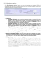
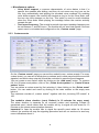
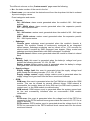
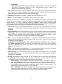
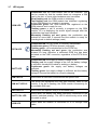
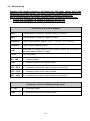
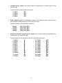
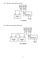
ProCOM GSM ADAPTER INSTALLATION AND APPLICATION MANUAL For module version v1.0 and higher Rev. 1.2 2010.07.12 Table of Contents 1 Basic functions of the ProCOM GSM Adapter .......................................................... 3 1.1 Functions and services.......................................................................................... 3 2 Programming the ProCOM........................................................................................ 3 2.1 Configuring through USB connection .................................................................... 4 2.2 Configuring through modem connection ............................................................... 4 2.3 Parameter settings ................................................................................................ 5 2.3.1 Phone numbers ............................................................................................. 5 2.3.2 Miscellaneous options ................................................................................... 7 2.3.3 Custom events ............................................................................................... 8 2.3.4 Incoming CID events ................................................................................... 11 2.3.5 Inputs ........................................................................................................... 12 2.3.6 Firmware ...................................................................................................... 13 2.4 Settings management ......................................................................................... 14 2.5 Changing the module password .......................................................................... 14 2.6 Module status monitoring .................................................................................... 15 2.6.1 Downloading the event list ........................................................................... 18 2.7 Updating the software ......................................................................................... 19 2.8 General functioning method ................................................................................ 19 2.9 Record voice messages ...................................................................................... 20 2.10 Relay control and sabotage monitoring deactivation with SMS messages ....... 21 3 The ProCOM module peripherals ........................................................................... 23 3.1 Panel overview .................................................................................................... 23 3.2 SIM card slot ....................................................................................................... 23 3.3 Pushbutton .......................................................................................................... 23 3.4 Tamper protection ............................................................................................... 24 3.5 USB connector .................................................................................................... 24 3.6 Antenna connection ............................................................................................ 24 3.7 LED signals ......................................................................................................... 25 3.8 Module wiring ...................................................................................................... 26 3.8.1 Inputs and phone line wiring ........................................................................ 28 3.8.2 Expansion module inputs wiring .................................................................. 28 3.8.3 Relay outputs wiring .................................................................................... 28 3.8.4 12V power supply and battery wiring ........................................................... 29 3.8.5 24V power supply and battery wiring ........................................................... 29 4 Alarm panel preparation .......................................................................................... 30 4.1 Other notes ......................................................................................................... 30 5 Installation guide ..................................................................................................... 30 5.1 Installation ........................................................................................................... 30 5.2 Putting into operation .......................................................................................... 31 6 Technical details ..................................................................................................... 31 6.1 Technical specification ........................................................................................ 31 6.2 Generated phone line specification ..................................................................... 31 6.3 Package contents ................................................................................................ 32 6.4 Manufacturer’s contact information ..................................................................... 32 2 1 Basic functions of the ProCOM GSM Adapter The main function of the ProCOM GSM ADAPTER is to adapt those alarm systems to GSM network which are capable of communicating in Contact ID format to a monitoring station through PSTN, as well as transmitting the state of its inputs controllable by external contacts through GSM network. The adapter makes the installation of alarm systems possible in places where landline (PSTN) is not available, but reporting to a monitoring station is required. By means of GSM transmission, the adapter improves the reliability of alarm reporting in cases when the wired alarm transmission does not work or fails (e.g. when the phone lines are tampered or the telephone service is suspended due to technical reasons). 1.1 Functions and services Management of 2 independent SIM cards Reception of incoming calls, possibility for restriction Installable behind phone exchange servers Management of different prefix numbers for PSTN and GSM calls Forwarding of incoming SMS messages to 2 phone numbers Conversion of alarm report codes to SMS messages Storing the last 1000 events in the event list Supports voice dialers 4 onboard contact inputs and optional 24 input expansion module Reporting the state of 4+24 inputs to monitoring station, by voice call and by SMS 9 recordable voice messages and a siren tone for alarm transmission 4 configurable relay outputs, controllable by events or by user Backup battery management Built-in tamper protection 2 Programming the ProCOM The ProCOM GSM Adapter’s parameters can be set by the programming software found on the enclosed CD, either by connecting it with a PC through USB port directly, or with a GSM modem remotely. The package contains the necessary USB cable for USB connection. For remote connection a GSM modem (TELL GT64 is recommended) and a USB / RS232 adapter equipped with FTDI chip are necessary which can be purchased separately. 3 2.1 Configuring through USB connection Start the „ProCOM_Remoter” programming software Select the „USB” option on the „Connection” page Connect the module to the PC using the USB cable The programming software recognizes the connected device automatically The software asks for the module’s password, in case it is not set to default (1111) A green tick indicates when the connection is established Perform the desired settings, the following chapters will give a detailed description on the different functions of the ProCOM When finished, disconnect the module from USB 2.2 Configuring through modem connection For remote connection a GSM modem (TELL GT64 is recommended) and an FTDI chip equipped USB / RS232 adapter are necessary. GSM data call (CSD) service must be activated in the modem and on its SIM card. Steps for establishing modem connection: Start the “ProCOM_Remoter” programming software Select the “Modem” option on the “Connection” page Power up the GSM modem, then connect it to the PC with an FTDI chip equipped USB cable The programming software automatically recognizes the connected device Enter the ProCOM module’s phone number in the “Phone number” field using the country code as well Start dialing by pressing the “Establish connection” button The software asks for the module’s password, in case it is not set to default (1111) A green tick indicates when the connection is established 4 Perform the desired settings, the following chapters will give a detailed description on the different functions of the ProCOM When finished, close the connection by pressing the “Close modem connection” button 2.3 Parameter settings To set parameters, select the „Parameters” page. The different parameters of the ProCOM are divided into several subpages. 2.3.1 Phone numbers On the “Phone numbers” page the user and monitoring station phone numbers can be set. The phone numbers must be entered using the international format, with country code: Phone number (T1-T4): enter those user phone numbers here, to which reporting is required in case an event occurs (according to event settings), or from which the ProCOM should accept commands. Other phone number: it can be configured the same way as for the user phone numbers, how the ProCOM should handle incoming calls from phone numbers other than T1-T4 user phone numbers. Acknowledgement: three acknowledgement methods are available: o No acknowledgement: event acknowledgement is not required. o = ack: events have to be acknowledged by pressing the phone’s key o = ack, # = stop: events have to be acknowledged by pressing the phone’s key, furthermore by pressing the # key the actual event’s alarm calls to the other user phone numbers can be cancelled, while also acknowledging the event. By dialing 9password#, all events waiting to be notified are stopped (e.g. in case the password is default: 91111#) 5 If acknowledgement request is set, the module will continuously recall the given phone number within the alarm time frame (10 minutes) until it is acknowledged. Incoming call handling: there are four different ways to handle incoming calls: o None (hangs up): the module rejects calls from the specific phone number o Relay control (T1-T4): the module rejects calls from the specific phone number, but executes the set relay control protocol (with free call and phone number identification) – this function requires call number visibility service enabled on the user’s phone. o Relay control (DTMF): the module receives the call from the specific phone number, thereby relay control can be executed by the phone’s buttons. The controlled relay will execute the task set with the programming software. Relay ON commands: relay 1.: 01 , relay 2.: 02 , relay 3.: 03 , relay 4.: 04 Relay OFF commands: relay 1.: #01 , relay 2.: #02 , relay 3.: #03 , relay 4.: #04 o Ring: the module will switch incoming calls from the specific phone number to the phone connected to the module’s output, which will ring, and voice communication is possible by accepting the call. R1-R4: the different relay control tasks can be set here that are triggered by incoming calls from specific phone numbers. This function is available when one of the „Relay control (T1-T4 /DTMF)” call handling options is selected. First, enable the relay output’s checkbox you want to control, then select the desired option: o State change: as the result of the incoming call, the relay output changes its state (if it was active, it changes to inactive, if it was inactive, it changes to active state) o ON – Monostable: as the result of the incoming call, the relay output becomes active for the duration set in the timing field, then reverts back to inactive state. The duration can be set between 0,1 – 600 seconds o ON – Bistable: the call activates the relay output for a prolonged time (the relay output stays active until a relay output off or state change control command arrives) o OFF: as the result of the incoming call, the relay output becomes inactive Monitoring station phone numbers (C1-C2): two phone numbers can be set for signaling events to monitoring stations Reporting to one of the numbers is sufficient: if this option is enabled, then in case the module successfully signals to one of the phone numbers set here, it will not start signaling to the other one. Otherwise, the module will continuously try to signal until it successfully signals to both phone numbers or the alarm duration expires. Important! If only one of the options of „Mon. st. 1 2” is enabled on the „Custom events” page, the module will signal only to the enabled phone number, even if the „Reporting to one of the numbers is sufficient” option is not set. SMS forwarding (1-2): the module forwards incoming SMS messages to the phone numbers set here, which is useful for receiving SIM card balance information messages, etc. (if left blank, the module will delete all incoming SMS messages). Important! Never set the phone number of the SIM card put in the module here, because the first SMS received by the module will start an infinite loop of SMS messages sent to itself, which will result in significant costs! 6 2.3.2 Miscellaneous options On „Miscellaneous options” page, you can set incoming and outgoing GSM call limitations, daily SMS limit, monitoring station user ID, the prefix numbers, voice dialer support and periodic test report frequency. Limitations: o Incoming GSM calls: you can set the maximum length of incoming GSM calls between 1 and 25 minutes with the slider. The module automatically hangs up when the set time expires. You can also set the length to „Unlimited” if you do not want the module to limit incoming call durations. o Outgoing GSM calls: you can set the maximum length of outgoing GSM calls between 1 and 25 minutes with the slider. The module automatically hangs up when the set time expires. You can also set the length to „Unlimited” if you do not want the module to limit outgoing call durations. o Daily SMS limit: you can set the maximum number of SMS messages the module can send in a 24 hour long period. If the number of SMS messages sent exceeds this limit, the module will not send any more SMS messages until the 24 hour duration expires, including alarm messages and forwarded SMS messages. You can also set the number to „Unlimited” if you do not want the module to limit the number of outgoing SMS messages. User ID for monitoring station: Here you can set the user ID necessary for ContactID signaling to monitoring stations (4 digit long, contains only the following characters: 0…9,A,B,C,D,E,F). For your user ID, please contact your monitoring station. Prefix numbers: o External line: if the module’s line (PSTN) input is connected to telephone subcenter and it requires a prefix number (for example: 9) to reach the main line, then this required prefix number has to be set here. The module will not use this number for GSM calls, only for calls on the PSTN line. o Prefix added in GSM mode: If you set a prefix here, the module will use it for calls made in GSM mode. For example, if the connected alarm panel dials a local phone number without prefix (e.g. 999999) the module can attach the prefix set here that is required for calls initiated on GSM (e.g. +3652, thereby the called number is: +3652999999). 7 Miscellaneous options: o Voice dialer support: a common characteristic of voice dialers is that if a specific time passes after dialing, and they do not sense any ring tone on the line, they automatically start playing the recorded voice message. By enabling voice dialer support, the module will simulate a ring to for the voice dialer until the true ring tone emerges on the line. This option is used to avoid situations when the voice dialer starts playing the message before the receiver actually accepts the call. o Test report frequency: The module’s periodic test report sending frequency can be set between 1 and 240 hours. The module will not send test reports if the test report event is not added and configured on the „Custom events” page. 2.3.3 Custom events On the „Custom events” page you can set the module’s own, custom events. For every custom event, you can set to which phone numbers and in what way should the event be signaled, and which relay output(s) should be controlled in case the event happens. You can create a new custom event by clicking on the „Add event” button. To create a full 4 or 28 zone event pattern, click on the „Create 4 zone pattern” or „Create 28 zone pattern” button. You can delete a custom event by first selecting it, then clicking on the „Delete event” button. You can select and event by clicking on its index number or the empty area below it. The maximum number of „custom events” together with the „incoming CID events” is 100. The module’s alarm duration (event lifetime) is 10 minutes for every event. The alarm duration is separate for all occurred custom and incoming Contact ID generated event, which means that the module will try to signal all such event for 10 minutes on the preset communication channels. Important! In case the module fails to signal the specific event within its 10 minute interval, the module will stop the signaling procedure and will not continue to send any more notifications about it. 8 The different columns on the „Custom events” page mean the following: No.: the index number of the event in the list Event name: you can select the desired event from the drop-down list that is ordered by event category names Event categories and events: o Alarms: IN1…IN4 alarm: alarm events generated when the module’s IN1…IN4 inputs activate XIN1…XIN24 alarm: alarm events generated when the expansion panel’s IN1…IN24 inputs activate o Restores: IN1…IN4 restore: restore event generated when the module’s IN1…IN4 inputs restore XIN1…XIN24 restore: restore event generated when the expansion panel’s IN1…IN24 inputs restore o Sabotage: Chassis open: sabotage event generated when the module’s chassis is opened. The module’s chassis is continuously monitored by an integrated optical sensor. Sabotage monitoring can be turned off for 1..60 seconds for service tasks if required by SMS command (see chapter „Relay control and sabotage monitoring deactivation with SMS messages” for details) Chassis closed: restore event generated when the module’s chassis is closed back o Battery: Battery fault: this event is generated when the battery’s voltage level goes outside the following intervals: 10–14V, 20–28V Battery restore: battery restore event is generated when the battery’s voltage level goes back into the above mentioned intervals o Supply voltage: Supply voltage fault: this event is generated when the supply voltage level goes outside the following intervals: 13,5–14V, 27–28V Supply voltage restore: supply voltage restore event is generated when the supply voltage level goes back into the above mentioned intervals o GSM: GSM error: this event is generated when the ProCOM fails to initialize the GSM module. This can be caused by several different things: GSM network is inaccessible, the module does not find a SIM card (no SIM card is present, or contact error), or the GSM module is malfunctioning. GSM restore: GSM restore event is generated when the system comes back on line and successfully initializes after an unsuccessful GSM module initialization. o PSTN: PSTN error: this event is generated when the voltage level of the PSTN line connected to the PSTN terminal boxes goes outside the interval of 5–75V for at least 30 seconds PSTN restore: PSTN restore event is generated when the voltage level of the PSTN line connected to the PSTN terminal block comes back into the above mentioned interval 9 o Test event: Test event: periodic test event (life sign), which will be sent at the time period set under „Test report frequency” on the „Miscellaneous options” page if it is added and configured as an event CID code: the event’s 4 digit Contact-ID code, in which the first digit represents the new event (“1”) or event restore (“3”), while the other 3 digits are the actual event code, which can be found in the Contact ID code table. Partition: the partition’s number, in which the event occurs (01…99) Zone: the zone’s number, in which the event occurs (001…999) When a new event row or pattern is created, the software automatically offers the default Contact-ID codes for the events. The default setting puts the base panel’s IN1…IN4 inputs’ zones 1.-4. in the 1. partition, while the expansion panel’s XIN1…XIN24 inputs’ zones 1.-24. in the 2. partition. In case the default setting is not suitable for application, any parameter of the full Contact-ID code can be freely customized. Voice call 1…4: by selecting checkboxes 1…4, you can select which user phone numbers (1…4) should be notified through GSM voice call when the specific event happens. Voice message: from the drop down list you can select which user recorded message („Message 1…9”) or the default „Siren tone” shall be played when the specific event occurs and the enabled user phone number is called. On how to record a voice message, please consult the chapter „Record voice messages”. Mon. st. 1…2: by selecting checkboxes 1…2, you can select which monitoring station phone numbers should be notified through GSM voice call in Contact-ID format when the specific event happens. Important! If the „Reporting to one of the numbers is sufficient” option is set on the “Phone numbers” page, the module will send report to only one of the numbers (the first it successfully reports to), even if both checkboxes are set under the „Mon. st. 1 2” option. SMS 1…4: by selecting checkboxes 1…4, you can set to which user phone numbers the module shall send an SMS notification of the specific event. SMS message: the customizable SMS text message that will be sent to the enabled user phone numbers (1…4) when the specific event occurs. The maximum length of the text is 80 characters. R1-R4: the different relay controls for all 4 relays can be set here that shall be executed when the specific event occurs. To control a relay output, check the corresponding R1-R4 checkbox and select the desired option: o State change: as the result of the event, the relay output changes its state (if it was active, it changes to inactive, if it was inactive, it changes to active state) o ON – Monostable: as the result of the event, the relay output becomes active for the duration set in the timing field, then reverts back to inactive state. The duration can be set between 0,1 – 600 seconds o ON – Bistable: the event activates the relay output for a prolonged time (the relay output stays active until relay output off or state change control) o OFF: as the result of the event, the relay output becomes inactive 10 2.3.4 Incoming CID events On the „Incoming CID events” page, you can set whether the module shall generate customizable SMS text messages or voice calls of the events arriving from the alarm panel and forwarded to the monitoring station through GSM or PSTN line. These SMS and voice calls are forwarded to the enabled user phone numbers (Contact-ID based SMS and/or voice message generation and notification). If you do not want to forward the alarm panel’s signals to a monitoring station, you still have the option to forward the events received from the alarm panel as GSM voice calls and SMS messages. For this, set 123456789 as the monitoring station’s phone number. The alarm panel will dial this number when it has to send an event. The module will recognize this number and will simulate a monitoring station receiver, gives out the handshake signal and acknowledges the received Contact-ID signals, then forwards it as GSM voice call and/or SMS, according to the actual settings. Important! In case an event of the same type is generated while the module is already forwarding an event of such type, the new event will not be forwarded, the module will not signal multiple instances of the same event type after each other. You can create a new event row by clicking on the „Add CID event” button. You can delete an existing CID event by first selecting it, then clicking on the „Delete CID event” button. You can select and event by clicking on its index number or the empty area below it. The maximum number of „custom events” together with the „incoming CID events” is 100. The module’s alarm duration (event lifetime) is 10 minutes for every event. The alarm duration is separate for all occurred custom and incoming Contact ID generated events, which means that the module will try to signal all such event for 10 minutes on the preset communication channels. In case the module fails to signal the specific event within its 10 minute interval, the module will stop the signaling procedure and will not continue to send any notification about it. The different columns on the „Incoming CID events” page means the following: No.: the index number of the event in the list CID code: the event’s 4 digit Contact-ID code, in which the first digit represents the new event (“1”) or event restore (“3”), while the other 3 digits is the actual event code, which can be found in the Contact ID code table. Partition: the partition’s number, in which the event occurs (01…99) Zone: the zone’s number, in which the event occurs (001…999) In the default setting, the Contact-ID code is filled with star characters, which means that for any Contact-ID the module will generate a voice call and SMS and sends it to the allowed user phone numbers. Event filtering is possible by setting specific event code/partition/zone parameters. 11 (For example: In case of the following setting „CID code: 1130 , Partition: 01 , Zone: 004, SMS: 1,2 enabled, SMS text: Break-in Zone 4 – living room” the module will send the above mentioned SMS text to user phone numbers 1 and 2 if the Contact-ID code received from the alarm panel is identical with the set parameters, meaning that the break-in signal happens in the 1. partition and 4. zone). It is also possible to define event groups with the star character. The star character behaves as a joker character and substitutes any number on the specific digit of the event code, partition or zone number. (For example: for event codes, the 13 represents all event codes that start with 13). Voice call 1…4: by selecting checkboxes 1…4, you can select which user phone numbers (1…4) should be notified through GSM voice call when the specific event happens. Voice message: from the drop down list you can select which user recorded message („Message 1…9”) or the default „Siren tone” shall be played when the specific event occurs and the enabled user phone number is called. On how to record a voice message, please consult the chapter „Record voice messages”. SMS 1…4: by selecting checkboxes 1…4, you can set which user phone numbers the module shall send an SMS notification of the specific event. SMS message: the customizable SMS text message that will be set to the enabled user phone numbers (1…4) when the specific event occurs. The maximum length of the text is 80 characters. R1-R4: the different relay controls for all 4 relays can be set here that shall be executed when the specific event occurs. To control a relay output, check the corresponding R1-R4 checkbox and set the desired option: o State change: as the result of the event, the relay output changes its state (if it was active, it changes to inactive, if it was inactive, it changes to active state) o ON – Monostable: as the result of the event, the relay output becomes active for the duration set in the timing field, then reverts back to inactive state. The duration can be set between 0,1 – 600 seconds o ON – Bistable: the event activates the relay output for a prolonged time (the relay output stays active until a relay output off or state change control command arrives) o OFF: as the result of the event, the relay output becomes inactive 2.3.5 Inputs On the „Inputs” page the module’s and the zone expansion panel’s inputs and alarm restrictions can be configured. 12 IN1…IN4: the module’s 4 contact input XIN1…XIN24: the expansion panel’s 24 contact input Input type: three different options can be selected from the drop down list separately for every input: o Inactive: the input is not in use, the module does not monitor the specific input o Normally open (NO): the input is normally open, closing the specific input and the COM common point will generate a new event, while opening it will generate a restore o Normally closed (NC): the input is normally closed, which means that the specific input and the COM common point is closed, opening it will generate a new event, while closing back generates a restore Limitation of alarms per input: o Maximum number of alarms per zone: with the slider you can set the maximum number of signals the module shall notice. This is a global setting which affects all inputs. With this you can avoid that a faulty sensor continuously sends alarm signals. After the restriction period expires, the specific input is enabled again, meaning that it can generate alarms, but only up to the maximum number set in this option. If you select the „Unlimited” option (right side of the slider), the module will not limit the number of signals of the inputs. o Alarm restriction period: You can set it between 1 and 24 hours that for how long the module shall ignore signals from zones that have already reached the maximum number of alarm signals set under the „Maximum number of alarms per zone” option. When the duration set here expires, the alarm counter is automatically set to zero and the specific zone becomes enabled again. 2.3.6 Firmware The module’s software can be updated on the „Firmware” page, if it is reasonable and necessary. The firmware (the module’s software) defines the module’s work and functions. Uploading inappropriate or defective firmware to the ProCOM module will result in malfunction and damages the module! Steps for updating the firmware: power on the ProCOM module establish connection between the programming software and the ProCOM module after clicking on the „Browse…” button, please select the appropriate firmware file to start the upload, please click on the „Upload firmware file” button the progress bar at the bottom shows the upload procedure’s current progress after the upload is finished, the module will automatically restart, after which you can upload the necessary settings and verify the correct functioning 13 2.4 Settings management You can easily manage and archive your settings with the seven buttons found on the upper section of the „Parameters” page. The seven buttons’ functions from left to right: Read parameters from file, Save parameters to file, Save parameters to file in printable format, Read parameters from module, Upload parameters to module, Compare parameters with the module and Change module password. After you have finished the settings, upload them to the module with the upload button. The upload/download progress is shown on the progress bar found at the bottom of the software window. The new settings are activated only after the upload has successfully finished. 2.5 Changing the module password To change the module password, first click on the „lock” button, then fill out the text fields and click on the OK button. In case you forgot the password, you can not change it, therefore you have to reset the module back to its default state, which will also reset the password back to the default 1111. On how to reset the module back to default, please consult the chapter „Pushbutton”. Warning! In case you reset the module back to its default state, all previously set parameters also revert back to their default, which means that the module’s settings are erased. 14 2.6 Module status monitoring The ProCOM module’s actual status (PSTN line, inputs, relay outputs, GSM line and signal strength, voltage levels, event list and module messages) is shown on the „Status” page. Input status icons: Icon Meaning Input not configured – not functioning The input is in normal state The input is in active state – alarm Normally open (NO) – normal state Closed contact – Normally open input activated Normally closed (NC) – normal state Open contact – normally closed state activated 15 Elements and available functions on the software window: Inputs: - - Relay1…Relay4: displays the state of the main panel’s 4 relay outputs. Active relays are represented by a green light. „On/Off” button: the On/Off buttons are used to activate/deactivate the selected relay output while the module and the software are connected. ProCOM module window: - displays the state of the main panel’s 4 main inputs displays the state of the expansion panel’s 24 inputs Relay outputs: - IN 1…IN 4: XIN 1…XIN 24: Firmware version: the connected module’s firmware version and date Internal clock: the connected module’s internal clock „Synchronize” button: this button is used to synchronize the connected module’s internal clock with the computer’s clock Supply voltage: the input supply voltage level of the module Battery voltage: the voltage level of the battery connected to the module Charging: Yes: the battery is currently charging No: the battery is not charging, or no battery is present Chassis: Open/Closed: shows the current state signaled by the optical sabotage sensor Speaker: On/Off: shows the state of the built-in speaker Line emulation (SLIC) window: - Status: shows the state of the simulated GSM line: On hook/Off hook: the state of the line Line error (voltage): the module is unable to set the line voltage because the line is overloaded (short circuit on the line) Line error (no answer): hardware error Line error (DC): the line generator is unable to set the supply voltage, which can be caused by low voltage levels on the module’s input or the supply current is too low for proper functioning Line error (current): the current is too high on the line Unknown: other unknown error has occurred on the line 16 GSM module window: - displays the GSM module’s state: Registration in progress: registering on the GSM network is currently in progress Active: the GSM module is registered on the network and is ready Inactive: the GSM module failed to register on the GSM network GSM signal: displays the current GSM signal strength on a scale of 0-31 SIM1-2: displays whether a SIM card is present in which SIM socket, and that which is currently active Network: displays the currently active SIM card’s network (GSM service provider) PSTN module window: - Status: Line voltage: displays the voltage level of the phone line connected to the PSTN input Event list window: The event list shows the module’s events, ordered by their time of occurrence. The list is automatically refreshed every second. o o o o o o o The different signs and meanings of columns T1-T4, S1-S4 and C1-C2: o o o o o o Index: the index number of the event Event: the name of the event Contact-ID code: the 16 digit long Contact-ID of the event T1 … T4: notifications through voice call to user phone numbers 1…4 S1 … S4: notifications in SMS to user phone numbers 1…4 C1 … C2: report sending to monitoring station phone numbers 1…2 Date/Time: the date and time of the event’s occurrence ? - event processing/notification is currently in progress * - signal sending successful R - signal sending already successful through another way, it is unnecessary to send notification here ! - signal sending was unsuccessful S - alarm has been stopped, it is unnecessary to send notification here T - time limit expired, signal sending was unsuccessful within the alarm duration interval State messages window: The module’s latest messages with timestamps are displayed here. These messages can be filtered by selecting the appropriate checkboxes of „Procom messages”, „GSM module messages”, „DTMF messages” and „Event messages”. The message window’s content can be exported to file by clicking on the „Export message window” button, or cleared by clicking on the „Clear message window” button. 17 2.6.1 Downloading the event list To download the detailed event list, please click on the „Detailed event list” button found on the „Status” page. The module stores the last 1000 events in memory. Number of event list rows: the number of events the software will display in the list, starting from the most recent event Download: start downloading the event list with this button Save list: the list content can be saved to an Excel file with this button Event list columns: o o o o o o o Index: the index number of the event Event: the name of the event Contact-ID code: the 16 digit long Contact-ID of the event T1 … T4: notifications through voice call to user phone numbers 1…4 S1 … S4: notifications in SMS to user phone numbers 1…4 C1 … C2: report sending to monitoring station phone numbers 1…2 Date/Time: the date and time of the event’s occurrence The different signs and meanings of columns T1-T4, S1-S4 and C1-C2: o o o o o o ? - event processing/notification is currently in progress * - signal sending successful R - signal sending already successful through another way, it is unnecessary to send notification here ! - signal sending was unsuccessful S - alarm has been stopped, it is unnecessary to send notification here T - time limit expired, signal sending was unsuccessful within the alarm duration interval 18 2.7 Updating the software On the „Update” page, you can specify how the programming software should be updated. Update: if automatic update is selected, the software will check for updates every 20 minutes. In case of manual mode, the software will check for updates when the „Search for program updates” button is clicked. Enable automatic updating: if this option is enabled, the software will automatically download updates without user intervention, then automatically restarts itself upon a successful download. If not enabled, the software will ask for confirmation before it starts the software update procedure. Search for program updates: by clicking this button, the software starts the update procedure. 2.8 General functioning method In case of two SIM cards used, the module will treat both cards as equal. Upon initialization, the module will primarily use the card inserted into the SIM1 slot to connect to the GSM network. If unsuccessful, it switches to the card inserted into the SIM2 slot. By default, all events are forwarded through GSM. If the GSM connection is inaccessible, (for example: no signal strength), the module switches to an alternative signal forwarding method. If PSTN line is present, the module will use it to forward the connected alarm panel’s signals in reserve mode. If no PSTN line is present, the module will keep sending a busy signal on the simulated phone line until connection is re-established on one of the channels. 19 2.9 Record voice messages The ProCOM module is capable of storing 9 separate (maximum 5 seconds long) voice messages, and play it back during GSM voice call notifications as configured. You can record voice messages with the help of a telephone device. To record or play back a voice message, connect the telephone to the module’s „LINE” input, then pick up the receiver and dial 000000000 (9 zeros). The module will send a 1 second long beep through the telephone, after which you can issue commands as following: Command 01 02 03 04 05 06 07 08 09 #01 #02 #03 #04 #05 #06 #07 #08 #09 Operation Start recording voice message no. 1. Start recording voice message no. 2. Start recording voice message no. 3. Start recording voice message no. 4. Start recording voice message no. 5. Start recording voice message no. 6. Start recording voice message no. 7. Start recording voice message no. 8. Start recording voice message no. 9. Play back voice message no. 1. Play back voice message no. 2. Play back voice message no. 3. Play back voice message no. 4. Play back voice message no. 5. Play back voice message no. 6. Play back voice message no. 7. Play back voice message no. 8. Play back voice message no. 9. After issuing a command, the start of the voice recording is signaled by a short beep. After this you can say what you want to record as a message. For the sake of good quality, say your message loud and near the receiver. If the record or playback is ended, a long beep will signal that the module is ready to accept the next command. The module automatically quits voice recording mode, if the caller hangs up, or an error occurs on the line. 20 2.10 Relay control and sabotage monitoring deactivation with SMS messages It is possible to control the module’s outputs and deactivate sabotage monitoring by sending the appropriate command in SMS to the module’s phone number as following: SMS command Operation R1=ON, PWD=yyyy, CRQ# Relay1 ON (bistable mode) If required, substitute “yyyy” with the module password, see explanation at the table’s bottom R2=ON, PWD=yyyy, CRQ# Relay2 ON (bistable mode) If required, substitute “yyyy” with the module password, see explanation at the table’s bottom R3=ON, PWD=yyyy, CRQ# Relay3 ON (bistable mode) If required, substitute “yyyy” with the module password, see explanation at the table’s bottom R4=ON, PWD=yyyy, CRQ# Relay4 ON (bistable mode) If required, substitute “yyyy” with the module password, see explanation at the table’s bottom R1=OFF, PWD=yyyy, CRQ# Relay1 OFF If required, substitute “yyyy” with the module password, see explanation at the table’s bottom R2=OFF, PWD=yyyy, CRQ# Relay2 OFF If required, substitute “yyyy” with the module password, see explanation at the table’s bottom R3=OFF, PWD=yyyy, CRQ# Relay3 OFF If required, substitute “yyyy” with the module password, see explanation at the table’s bottom R4=OFF, PWD=yyyy, CRQ# Relay4 OFF If required, substitute “yyyy” with the module password, see explanation at the table’s bottom R1=ONx, PWD=yyyy, CRQ# Relay1 ON for „x” (1-254) seconds (monostable mode) Substitute „x” with the desired time duration „x” can be between 1 – 254 seconds If required, substitute “yyyy” with the module password, see explanation at the table’s bottom R2=ONx, PWD=yyyy, CRQ# Relay2 ON for „x” (1-254) seconds (monostable mode) Substitute „x” with the desired time duration „x” can be between 1 – 254 seconds If required, substitute “yyyy” with the module password, see explanation at the table’s bottom R3=ONx, PWD=yyyy, CRQ# Relay3 ON for „x” (1-254) seconds (monostable mode) Substitute „x” with the desired time duration „x” can be between 1 – 254 seconds If required, substitute “yyyy” with the module password, see explanation at the table’s bottom 21 R4=ONx, PWD=yyyy, CRQ# TAMPEROFF=z, PWD=yyyy, CRQ# Relay4 ON for „x” (1-254) seconds (monostable mode) Substitute „x” with the desired time duration „x” can be between 1 – 254 seconds If required, substitute “yyyy” with the module password, see explanation at the table’s bottom Sabotage monitoring OFF (for 1-60 minutes) Substitute „z” with the desired time duration „z” can be between 1 – 60 minutes If required, substitute “yyyy” with the module password, see explanation at the table’s bottom yyyy = module password (default: 1111, optional parameter, necessary only from those phone numbers which are not configured in the module, because these are considered unauthorized by default, thereby they have to be authenticated by this password). The module will reject all SMS commands arriving from unauthorized phone numbers if they do not contain the module password. CRQ = request answer SMS from the module about task completion (optional parameter, necessary only when an answer SMS from the module about task completion is required). All commands must start with a star "" character, and end with a hashmark "#" character. Multiple commands can be issued in one SMS, but the maximum length is 160 characters total. If the SMS exceeds 160 characters, the module will process the first 160 characters only. SMS answers from the module (in case the CRQ parameter is used): Example: Rel1 ON Rel2 OFF = Relay1 turned ON = Relay2 turned OFF Examples for SMS commands: o Relay1 continuous ON (bistable mode): In case the command is sent from a phone number set in the module as a user phone number, and no SMS answer is required, the SMS command looks as the following: R1=ON# In case the command is sent from a phone number set in the module as a user phone number, and SMS answer is required, the SMS command looks as the following: R1=ON, CRQ# In case the command is sent from a phone number not set in the module as a user phone number, the module password becomes necessary, and the SMS command looks as the following: R1=ON, PWD=1111# (in case the module password is 1111) In case the command is sent from a phone number not set in the module as a user phone number, and SMS answer is required, the SMS command looks as the following: R1=ON, PWD=1111, CRQ# (in case the module password is 1111) 22 o Sabotage monitoring turned off for 20 minutes: In case the command is sent from a phone number set in the module as a user phone number, and no SMS answer is required, the SMS command looks as the following: TAMPEROFF=20# In case the command is sent from a phone number set in the module as a user phone number, and SMS answer is required, the SMS command looks as the following: TAMPEROFF=20, PWD=1111, CRQ# (in case the module password is 1111) 3 The ProCOM module peripherals 3.1 Panel overview 3.2 SIM card slot There are two SIM card slots on the panel (SIM1 and SIM2). You can insert the SIM card(s) here. The two SIM slots are functionally equal. SIM cards required for the ProCOM to function can be acquired at any GSM service provider. The ProCOM accepts all network providers’ SIM cards. 3.3 Pushbutton The pushbutton’s (marked as „PB” on the panel) functions: GSM signal strength display Push the button for a short time (<1 sec) and the module’s GSM LED (green) flashes the current GSM signal strength according to a 10-point scale. 23 3.4 Speaker ON/OFF Continuously push the button for at least 2, but maximum 5 seconds then release it to turn on the module’s speaker, which is used for diagnostic tasks (to hear the actual communication the line). The speaker stays on for 3 minutes, then automatically turns off. Switch to GSM Continuously push the button for at least 5 seconds, then release it in order to make the module switch to simulated GSM line for at least 30 seconds, regardless of the PSTN line’s state. It automatically reverts back to normal line management after the time period expires. This state is represented by the alternating flashing of the GSM LED (green) and PSTN LED (red). Reset (switch back to default settings) Continuously push the button for at least 5 seconds, then release it in order to reset the module back to its default settings. This state is represented by the GSM LED’s alternating red and green flashing. The reset procedure’s prerequisite is that all SIM cards are removed from their sockets. In this case, after the long button push (>5 sec), you have to push both concealed buttons (SIM card sensor switch) simultaneously to reset the default settings and restart the module. Tamper protection The ProCOM module is equipped with optical approach-sensor tamper protection. The optical sensor is integrated on the panel, next to the SIM2 card slot. Its work is lightreflection based, it senses the surface in front of the panel (for example the metal box’s door), and generates a tamper event when it is removed, and a restore event when it is put back to its original place. In order to correctly function, the surface in front of the panel should be light colored and matte. In case the module is installed into a box that’s surface in front of the panel is dark colored or shiny, reflective, then put a white paper or decal in front of the panel. By default (the box is closed) the panel and the surface in front of it should not be farther than 50mm from each other. Any greater space may result in improper functioning of the optical sensor, which may result in fake alarms. If you do not want to use the tamper protection function, you can disregard the above mentioned things. 3.5 USB connector The USB connector on the panel is used to establish direct USB connection between the ProCOM module and a computer through a USB cable. With this, you can easily connect the module to the programming software found on the product’s install CD. To establish connection, a USB A-B cable is required, which is contained within the product package. 3.6 Antenna connection The GSM antenna can be connected to the FME (spike) connector slot. The antenna found in the product package guarantees good transmission in normal environments. In case of signal strength problems and/or wave interferences (fading) use another antenna with better gain, or find a more favorable place for the module. 24 3.7 LED signals GSM LED PSTN LED BATT LED Continuous red: the GSM module can not be initialized. This can be caused by that the module does not recognize a SIM card in the slot, or some other hardware error has arisen. Slow flashing red: the GSM module is initializing. Fast flashing red: the GSM module has initialized, registering on the GSM network is currently in progress. Continuous green: the GSM module has registered on the GSM network, and is ready for use. Flashing green: a call is currently in progress on the GSM module, or it is displaying the actual signal strength after the pushbutton has been released. Alternately flashing red and green: the pushbutton was pushed for more than 5 seconds and the module is ready for reverting back to default settings (reset). Continuous red: no PSTN line, or currently inaccessible. Continuous green: PSTN line present, and ready. Flashing green: off hook detected on the PSTN line. Alternately flashing red and green: the pushbutton was pressed for long, therefore a simulated GSM line has been activated on the LINE connector, regardless of the PSTN line’s state. Continuous red: the supply or battery voltage is low. Flashing red: the supply voltage is low, but the battery voltage is sufficient, thereby the module is working on battery. Continuous green: the supply and battery voltages are sufficient. Flashing green: the supply voltage is sufficient, but the battery voltage is low and the battery is currently charging. SIM LED1-2 Active when a SIM card is inserted into the specific slot. SIM ACT LED1-2 The active led represents the SIM card currently used by the module. If the led is flashing, the GSM module is searching for an available SIM card. REL LED1-4 Active when the specific relay is in activated state. BATT POL LED Active when the battery has been improperly connected to the module (switched polarity). The LED is continuously active while this state is active. USB LED Active when the module is connected to a PC through USB cable. 25 3.8 Module wiring Attention! The module requires a 12V battery for 12V power supply, and a 24V battery for 24V power supply! The charge controller automatically recognizes the connected battery type and adjusts the necessary charging voltage level. Due to security reasons, the charge controller does not enable charging when: In case of a 12V battery, its voltage is under 10V or over 14V In case of a 24V battery, its voltage is under 20V or over 28V Connectors of the ProCOM panel BATT+ External battery connector, positive polarity: 12/24VDC BATT- External battery connector, negative polarity 12/24VDC+ Power supply positive polarity: 13,5V – 14V DC; 27V – 28V DC 12/24VDC- Power supply negative polarity LINE Simulated line output from the GSM network (should be connected to the alarm panel’s RING-TIP input) PSTN PSTN line input IN1…IN4 1…4 contact inputs COM 1…4 common point of the contact inputs NC1…NC4 1…4 normally closed relay outputs (opens on activation) CO1…CO4 1…4 common points of the relay contacts NO1…NO4 1…4 normally open relay outputs (closes on activation) Connectors of the ProCOM expansion panel I1…I24 1…24 contact inputs COM 1…24 common point of the contact inputs 26 Contact (zone) inputs: the contact shall be interpreted as a simple short circuit NO/NC type. Contact inputs on the terminal connector: 1. input: 2. input: 3. input: 4. input: IN1 IN2 IN3 IN4 Relay output: potential independent closing and opening relay contact inputs, their maximum load capacity is 5A/12VDC per relay. Contact outputs on the terminal connector: Relay1: Relay2: Relay3: Relay4: NC1, CO1, NO1 NC2, CO2, NO2 NC3, CO3, NO3 NC4, CO4, NO4 Extension module contact (zone) inputs: the contact shall be interpreted as a simple short circuit NO/NC type. Contact inputs on the extension module’s terminal connectors: 1. input: 2. input: 3. input: 4. input: 5. input: 6. input: 7. input: 8. input: 9. input: 10. input: 11. input: 12. input: I1 I2 I3 I4 I5 I6 I7 I8 I9 I10 I11 I12 13. input: 14. input: 15. input: 16. input: 17. input: 18. input: 19. input: 20. input: 21. input: 22. input: 23. input: 24. input: 27 I13 I14 I15 I16 I17 I18 I19 I20 I21 I22 I23 I24 3.8.1 Inputs and phone line wiring 3.8.2 Expansion module inputs wiring 3.8.3 Relay outputs wiring 28 3.8.4 12V power supply and battery wiring 3.8.5 24V power supply and battery wiring 29 4 Alarm panel preparation Please verify the following on the alarm panel for which you install the ProCOM module: Signaling format has to be set to either CONTACT ID or ADEMCO Express format. The monitoring station’s phone numbers must be set with area codes, in order to be accessible for the SIM card on GSM network. Dial method has to be set to TONE mode. 4.1 Other notes If it is used as a line adapter, the ProCOM will not know the length of the phone number it has to dial, therefore do not wait too much between the digits during dialing, because the module can take it as the dial procedure has ended. (To be exact, the module will wait 60 seconds for the dial to start after hook off. It starts calling numbers with less than 7 digits after a 5 seconds long pause, while it starts calling numbers with 7 or more digits after a 2 seconds long pause. After the above mentioned pause has expired, or the number of digits reached 32, the module will immediately start the calling procedure). In case of alarm panels, this does not pose a problem because of the fast dialing sequence, but you have to keep this in mind for manual dialing. 5 Installation guide 5.1 Installation Measure the GSM signal strength with your mobile phone. It is possible, that the desired place for installation has unsatisfactory levels of signal strength. With this simple measurement, you can modify the place of the module before installing it. Do not install the module where electro-magnetic disturbances can happen, for example near electrical motors. Do not install in moist, humid places. Antenna connection: the GSM antenna can be connected to the FME (spike) connector slot. The antenna found in the product package guarantees good transmission in normal environments. In case of signal strength problems and/or wave interferences (fading) use another antenna with better gain, or find a more favorable place for the module. For installing boxed versions it is mandatory to connect the protective ground to the metal box’s GND point! 30 5.2 Putting into operation Disable PIN-code request and voice mail service on the SIM cards you want to use in the module Enable caller identification and caller ID sending services at the GSM service provider of the SIM card (for some card types this is not enabled by default). Make sure that the SIM card is placed into its slot properly. Make sure that the antenna is connected to the module properly. Make sure that the wiring is according to the way it was mentioned earlier. Power up the module. If you use the panel-type ProCOM as a GSM adapter for alarm panels, make sure that the power supply is enough for the alarm panel and the module together. The quiescent current of the module is 120mA, however it can reach up to 500mA during communication and relay handling procedures. In case you want to use another power supply instead of the one supplied with the module, make sure that the voltage level is inside the interval necessary for battery charging: - 12V battery: 13,5V – 14V DC - 24V battery: 27V – 28V DC. Important! In case of power supplies with voltage levels outside the above mentioned intervals, the module will NOT charge the connected battery due to safety and security reasons! 6 Technical details 6.1 Technical specification Power supply voltage: Power supply voltage: Power supply voltage level necessary for battery charging: Nominal consumption: Maximum consumption: Operating temperature: Transmission frequency: GSM phone type: Connectable battery: Dimensions: Net weight: Gross weight (packaged): 6.2 9V – 30V DC 230VAC 13,5V – 14V DC or 27V – 28V DC 120mA /12VDC 500mA /12VDC -20ºC – +70ºC GSM 900/1800 MHz, 850/1900 MHz Simcom SIM340 12V-os: 13,5V – 14V DC power supply 24V-os: 27V – 28V DC power supply 150 x 110 x 19 mm (panel) 180 x 110 x 34 mm (panel + expansion module) 227 x 286 x 79 mm (metal box + GSM antenna) 200g (panel) 100g (expansion module) 2kg (boxed variant, with expansion, no battery) 2,1kg (boxed variant) Generated phone line specification Line voltage: Line current: Line impedance: Ring voltage: Tone: (for the panel-type variant) (for the factory boxed variant) 48 V 20 mA 600 Ohm ±50V (20 Hz) 425 Hz 31 6.3 Package contents Boxed type with zone expansion: ProCOM GSM Adapter EXT24 expansion module GSM 900MHz /1800MHz antenna Metal box Power supply 230VAC/12VDC 1,3A CD, user’s manual, warranty card USB A-B cable Boxed type without zone expansion: ProCOM GSM Adapter GSM 900MHz /1800MHz antenna Metal box Power supply 230VAC/12VDC 1,3A CD, user’s manual, warranty card USB A-B cable Panel type: ProCOM GSM Adapter GSM 900MHz /1800MHz antenna CD, user’s manual, warranty card USB A-B cable 6.4 Manufacturer’s contact information T.E.L.L. Software Hungária Kft 4034 Debrecen, Vágóhíd u. 2. Tel.: (52)-530-130 Fax.: (52)-530-131 Web: www.tell.hu 32