1
PR series
User Manual - Full Version
UMFPR01B
2nd Edition, 08/2015
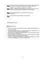
TABLE OF CONTENTS
1.
GENERAL DESCRIPTION ..................................................................... 8
1.1
UNIQUE FEATURES OF RECORDER ...................................................................................8
1.2
COMPARISON OF PR SERIES RECORDERS .....................................................................12
1.3
EXPANDABLE INPUT AND OUTPUT CARDS ......................................................................13
1.4
COMMUNICATION ..........................................................................................................14
1.5
EXTERNAL STORAGE MEDIA ..........................................................................................15
1.6
SMART MECHANISM .....................................................................................................16
1.7
ORDERING CODES AND ACCESSORIES ...........................................................................17
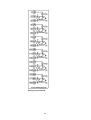
1.7.1
PR10 Ordering code ...........................................................................................17
1.7.2
PR20 Ordering code ...........................................................................................19
1.7.3
PR30 Ordering code ...........................................................................................21
1.7.4
Accessories:........................................................................................................23
1.8
2.
SPECIFICATIONS ...........................................................................................................24
INSTALLATION AND WIRING ............................................................. 29
2.1
UNPACKING..................................................................................................................29
2.2
INSTALLATION ..............................................................................................................29
2.3
PANEL MOUNTING STYLE ..............................................................................................30
2.4
SETUP INPUT AND OUTPUT ............................................................................................35
2.5
WIRING OF THE CARDS .................................................................................................41
2.6
RS-232, RS-422, AND RS-485 WIRING ........................................................................48
2.7
EXTERNAL MEMORY CARD: ..........................................................................................49
3.
BASIC FUNCTIONS OF RECORDERS ............................................... 50
3.1
CONFIGURATION...........................................................................................................50
3.2
STANDARD AND PLUS VERSION OF FIRMWARE...............................................................50
3.3
COMMUNICATION WITH THIRD PARTY INTERFACES .........................................................52
3.4
INFORMATION ACCESSIBILITY THROUGH WEB...............................................................52
3.5
HANDWRITING MESSAGES ON TREND SCREENS ............................................................53
3.6
CUSTOM EDITED DISPLAY SCREENS .............................................................................57
3.7
ANALOG INPUT LOG SPEED FLEXIBILITY .......................................................................58
3.8
HIGH SPEED INPUT .......................................................................................................58
3.9
SYSTEM CLOCK SYNCHRONIZATION VIA INTERNET .........................................................58
3.10
INCREASED SECURITY IN PASSWORD CONFIGURATION ...................................................58
3.11
AUTO OUTPUT TO PRINTER ..........................................................................................58
3.12
EXTERNAL CHANNELS ..................................................................................................58
2
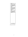
3.13
BATCH .....................................................................................................................58
3.14
FDA 21 CFR PART 11 ............................................................................................58
4.
CONFIGURATION................................................................................ 59
4.1
CHANNEL .....................................................................................................................60
4.1.1
Analog Input ........................................................................................................60
4.1.2
Digital Input .........................................................................................................67
4.1.3
Math Channel......................................................................................................69
4.1.4
Analog Output .....................................................................................................83
4.1.5
Digital Output ......................................................................................................84
4.1.6
External ...............................................................................................................84
4.1.7
Jobs.....................................................................................................................85
4.2
DISPLAY ......................................................................................................................88
4.2.1
Status Bar ...........................................................................................................89
4.3
TIMER ..........................................................................................................................91
4.4
CLOCK .........................................................................................................................94
4.5
COMMUNICATION ..........................................................................................................95
4.5.1
Connections ........................................................................................................97
4.5.2
Commands..........................................................................................................98
4.5.3
Modbus RTU Master, Example1.........................................................................99
4.5.4
Modbus RTU Master, Example2.......................................................................101
4.5.5
Modbus RTU Slave, Example...........................................................................103
4.6
INSTRUMENT ..............................................................................................................105
4.7
SECURITY ..................................................................................................................106
4.7.1
Normal...............................................................................................................106
4.7.2
CFR-21..............................................................................................................107
4.8
DEMO ........................................................................................................................108
4.9
AUTO-OUTPUT ...........................................................................................................108
4.9.1
USB Printer .......................................................................................................109
4.9.2
Network Printer (LPT1) .....................................................................................111
4.9.3
Print Historical data ...........................................................................................112
4.9.4
Print Reports .....................................................................................................114
4.9.5
Print Snapshot...................................................................................................115
4.10
SYSTEM INFO .........................................................................................................116
4.11
BATCH CONTROL ....................................................................................................119
4.12
CALIBRATE .............................................................................................................127
4.13
PROCEDURE TO RESET AND RESTORE FACTORY DEFAULT SETTINGS ......................144
3
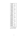
5.
PC BASED SOFTWARE .................................................................... 146
5.1
FREE BASIC SOFTWARE .............................................................................................146
5.1.1
Requirements....................................................................................................146
5.1.2
Operating system ..............................................................................................146
5.1.3
Software ............................................................................................................146
5.1.4
Ethernet Configuration ......................................................................................150
5.2
DATA ACQUISITION STUDIO SOFTWARE .......................................................................153
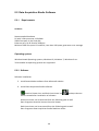
5.2.1
Requirements....................................................................................................153
Operating system ............................................................................................................153
5.2.2
Software ............................................................................................................153
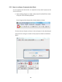
5.2.3
How to configure Communication Bank............................................................154
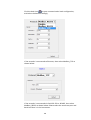
5.2.4
How to configure Recorder ...............................................................................156
5.2.5
Touch Screen....................................................................................................157
5.2.6
Ethernet.............................................................................................................157
5.2.7
Removable Media .............................................................................................161
5.2.8
Configuration.....................................................................................................165
5.2.9
How to view Historical data ...............................................................................176
5.2.10
How to view Real time data in PC.....................................................................184
5.2.11
Bank configuration ............................................................................................184
5.2.12
Ethernet.............................................................................................................186
5.2.13
Serial (RS232/422/485).....................................................................................189
5.2.14
View Real time data from Multiple Recorders...................................................190
5.3
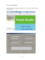
PANEL STUDIO VERSION .............................................................................................191
5.3.1
System Requirements.......................................................................................192
5.3.2
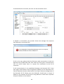
Software Installation..........................................................................................193
5.3.3
Project status ....................................................................................................194
5.3.4
Create new project ............................................................................................195
5.3.5
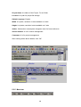
Menu bar ...........................................................................................................196
5.3.6
File ....................................................................................................................197
5.3.7
Environment ......................................................................................................198
5.3.8
Edit ....................................................................................................................200
5.3.9
Format...............................................................................................................201
5.3.10
View ..................................................................................................................203
5.3.11
Objects ..............................................................................................................205
5.3.12
Project ...............................................................................................................207
5.3.13
Standard bar .....................................................................................................207
5.3.14
Format bar ........................................................................................................208
5.3.15
Project Explorer.................................................................................................209
5.3.16
Screen...............................................................................................................210
5.3.17
Tool box ............................................................................................................213
4
5.3.18
Enhanced Objects.............................................................................................272
5.3.19
Graphics............................................................................................................300
5.3.20
Symbol Factory .................................................................................................308
5.3.21
Project Tools .....................................................................................................319
5.3.22
Build ..................................................................................................................319
5.3.23
Build & Offline Simulation..................................................................................320
5.3.24
Stop...................................................................................................................321
5.3.25
Build & Download ..............................................................................................321
5.3.26
Download ..........................................................................................................321
5.3.27
Project status ....................................................................................................323
6.
WEBSERVER..................................................................................... 324
6.1
REQUIREMENTS .........................................................................................................324
6.1.1
Hardware...........................................................................................................324
6.1.2
Operating system ..............................................................................................324
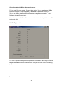
6.1.3
Browser Requirements .....................................................................................324
6.1.4
IP Address Requirements .................................................................................325
6.2
HOW TO CONFIGURE WEB SERVER SETTINGS ..............................................................325
6.2.1
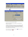
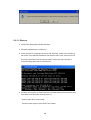
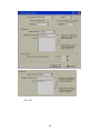
How to Configure Static IP Address..................................................................326
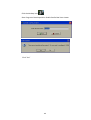
6.2.2
How to Enable Web Server...............................................................................327
6.3
HOW TO VIEW RECORDER DATA IN PC VIA WEBSERVER: ............................................328
5
Safety
This recorder is compliant with the requirements of EN61010-1, UL 61010C-1 & CSA
C22.2 No. 24-93. The protection provided by the recorder may be impaired if it is
used in a manner inconsistent with its intended purpose, or in an environment that
exceeds the specifications of the recorder. Brainchild Electronic Co., Ltd. is not liable
if the customer fails to comply with these requirements.
Safety Symbols
The following symbols may be seen in the user manual or on recorder labeling.
Caution
Protective Earth
DC Supply
Safety Notes and Precautions
1. Before any connection is made, the protective earth terminal should be connected
first. To avoid making the recorder dangerous under fault conditions, any
interruption of the protective Earth conductor inside or outside the recorder is
prohibited. Even in the case of a portable unit, the protective earth terminal must
remain connected if the recorder is connected to any hazardous voltage.
2. Keep signal and supply voltage wiring separated from one another. If this is
impractical, use shielded cables for signal wiring. Double insulation should be used
for signal wiring when the recorder is used with hazardous voltage.
3. Do not use the recorder where there is high vibration or a high magnetic field. This
could cause damage or error of measurement.
4. All maintenance or repairs should be carried out with power disconnected to avoid
personal injury or damage to the unit.
6
5. In areas with conductive pollution, adequate ventilation, filtering and sealing must
be installed.
6. When cleaning the recorder, handle carefully and use soft dry cloth. Avoid the use
of abrasives, or any sharp or hard objects which would damage the display.
7. Do not operate the recorder if any part has been removed or disassembled.
Consult your nearest dealer at once.
Static Electricity
Appropriate precautions must be taken when handling the recorder. The circuit
board components are susceptible to damage caused by electrostatic discharge.
Take static electricity precautions while handling and inserting USB memory into the
recorder.
.
NOTE: IF THE USER REQUIRES TO QUICKLY OR BRIEFLY
KNOW DETAILS OF THE FUNCTIONS , PLEASE
REFER THE QUICK USER MANUAL
7
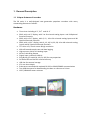
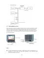
1. General Description
1.1 Unique features of recorder
The PR series is a well-designed new generation paperless recorders with many
outstanding features as follows:
Hardware
•
•
•
•
•
•
•
•
•
•
•
•
•
•
•
•
Three sizes including 4.3”, 5.6〞and 12.1”
PR10, with a 4.3” display, with 3 or 6 universal analog inputs and 24 Optional
External Channels
PR20, with a 5.6” display, with 6, 12 , 18 or 24 universal analog inputs and 48
Optional External Channels
PR30, with a 12.1” display, with 6, 12, 18, 24, 30, 36, 42 or 48 universal analog
inputs and 96 Optional External Channels
TFT Color LCD, Touch screen & high resolution
100 millisecond sample rate and data logging
High accuracy 24-bit A-D Analog Input
16-bit D-A Analog Output
Digital input, maximum 100 Hz.
Plug & play I/O cards (AI, AO, DI, DO) for easy expansion
On-board SD card slot for Internal memory
USB slot for external storage
171 mm short depth
Ethernet as standard with optional RS-232 or RS422/RS485 communication
Two USB Host ports for downloading the data or connect to Printer
IP65 / NEMA 4X water-resistant
8
Firmware and PC Software
•
•
•
•
•
•
•
•
•
•
•
•
•
•
•
•
•
•
Free Basic software for configuration, Historical viewer
Extensive Software- Data Acquisition Software for configuration,
Historical viewer and Real time viewer
View Circular Trends in PR30
Additional Panel Studio Software for editing and customizing displays
Display values in Digital, Real time trends, Historical trends, Bar graphs etc.
Real time and Historical alarms
Event management, Jobs linked with events
Reports (Daily, Weekly and Monthly)
Timers, Optional -Counters, Totalizers, Math channels and CFR-21
Customized messages for alarms
Alarms by email directly from paperless recorder
Batch control, log data in batches
100 msec. data logging and historical data archival tools
Display screen rotation
Dynamic Data Exchange via PC software
Search data with reference to time and period, then Export to spread sheets
Data logging by value change or time base
Start/Stop data logging functions which can be linked with real time clock or
events
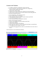
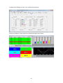
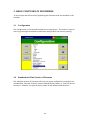
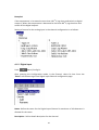
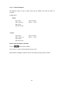
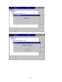
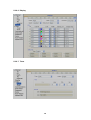
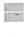
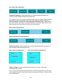
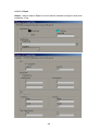
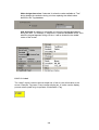
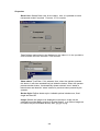
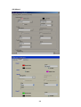
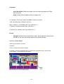
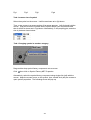
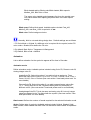
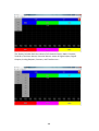
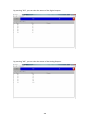
Historical Viewer in Free and Extensive Software:
9
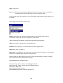
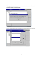
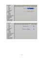
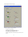
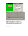
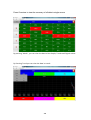
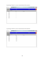
Configuration Editing in either Free or Extensive Software:
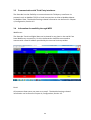
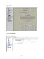
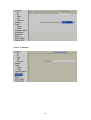
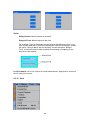
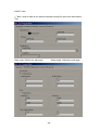
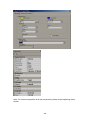
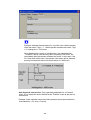
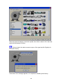
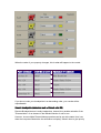
Extensive Software- Data Acquisition Studio with Real-time Viewer:
10
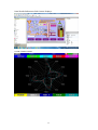
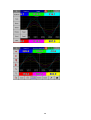
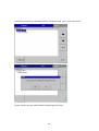
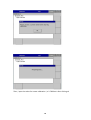
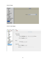
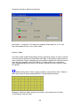
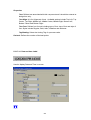
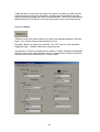
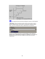
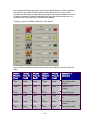
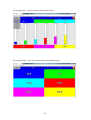
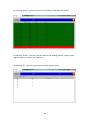
Panel Studio Software to Edit Custom Displays:
Circular Trends in PR30:
11
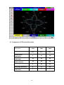
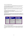
1.2 Comparison of PR series Recorders
Description
Display Size
PR10
PR20
PR30
4.3”
5.6”
12.1”
6
24
48
15
40
60
24
48
96
8
20
21
6
6
10
1
1
1
Analog Inputs
(Maximum)
Math Channels
(Maximum)
External Channels
(Other devices)
Total Pages
Pens/Page (Maximum)
Batches
(Maximum)
12
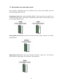
1.3 Expandable Input and Output cards
The recorder is equipped with rear expansion slots, which work flexibly with the
following plug & play I/O cards.
Analog Input cards (part number AI206 & AI203): These two cards are used for 3 or
6-channel analog inputs. Each input is isolated from each other to avoid noise and to
ensure stable measurement.
Relay Output card (RO206): Each card includes 6 alarm relays. Contacts are rated 5
Amp/240 VAC
Digital Input card (DI206): Each card includes 6 channels. Logic Low: -5V minimum,
0.8V maximum, Logic High: 3.5V minimum, 24V maximum
13
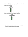
Combination Relay Output and Digital Input Card (RD233): Each Card includes
3 digital Inputs and 3 Relay Outputs. For Digital Inputs, Logic Low: -5V minimum, 0.8V
maximum, Logic High: -3.5V minimum, 24V maximum. For Relay Outputs, the
Contacts are rated 5 Amp/240 VAC
Analog Output cards (AO206): Each card includes 6 channels. They are used for
4-20mA, 0-20mA current output, 0-5V, 1-5V, 0-10VDC voltage output.
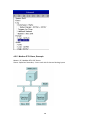
1.4 Communication
The standard communication interface is Ethernet with protocol IEEE 802.3 –
10/100 Base T. Other options are RS-232 / RS-422 / RS-485.
Details are explained in Chapter 2.6 - RS-232, RS-422, RS-485 wiring
14
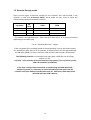
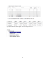
1.5 External Storage media
There are two types of External storage for the recorder, SD card and USB. If the
recorder is used with 6-channel inputs, we’ve made an easy chart to show the
maximum days based on available memory.
Log speed
1 second
10 seconds
120 seconds
SD
card
16GB
32GB
15, 808 days
31,616 days
158,032 days
1,896,304 days
316,064 days
3,792,608 days
* The above is an approximation , Each record of data uses 2 or 4 bytes of memory
depending on the data type.
For ex: Selected data size = 2 bytes
If the Log Speed (the recording speed of measured data) is set to the fastest speed
at 1 second per data, then for a six channels, a 16GB SD Card will last approximately
15, 808 days [16GB / (2 bytes x 24 hours x 60 minutes x 60 seconds x 6 Channels].
The following formula is to calculate how many days a USB disk can do saving
before it is full.
# of days = (The capacity of SD card memory x Log Speed) / (2 x # of hours per day
x 60 x 60 x Number of channels)
If the User is using USB to store data, to avoid losing recorded data while
transferring to PC, it is necessary to insert USB memory back again into the
recorder soon after loading recorded data onto PC. Otherwise, data may not be
recorded while the USB is absent.
15
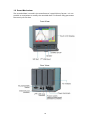
1.6 Smart Mechanism
The recorded data is stored in the manufacturer’s special binary format. It is not
possible to manipulate or modify the recorded data. This feature fully guarantees
the security of the data.
Front View:
Rear View:
16
1.7
Ordering codes and accessories
1.7.1 PR10 Ordering code
PR1003 (3 Analog Inputs)
–
□ □ □ □ □ □ □□
1 2 3 4 5 6 7 8
1 Additional Inputs and Outputs*
0: none
6: 3 relays + 3 DI
PR1006 (6 Analog Inputs)
1 Additional Inputs and Outputs
0: none
1: 6 relays
3: 6DI
6: 3 relays + 3 DI
7: 6 relays + 6 DI
2 Power
A: 90-250 VAC, 50/60 Hz
D: 11-36 VDC
3 Communication
0: standard Ethernet interface
1: Ethernet + RS-232
2: Ethernet + RS-422/485
4 Firmware
0: Standard Version
1: Plus Version 1 with extra mathematics, external channels, batch & FDA 21 CFR
part11
2: Plus Version 2 with editable custom display and Panel Studio software
3: Plus Version 3- includes Plus version 1+2 above
5 PC Software
1: Free Basic Software of Historical Viewer and Configuration
2: Extensive software Data Acquisition Studio
(Real Time Viewer + Historical Viewer + Configuration)
17
6 Mounting types, Power Cord & Switch
0: panel mount, no power cord, no power switch
1: panel mount, no power cord, power switch
2: portable, UL & CSA power cord, power switch
3: portable, VDE power cord, power switch
4: portable, SAA power cord, power switch
5: portable, BS power cord, power switch
6: portable, no power cord, power switch
7 & 8 Special options
00: none
01: 16G SD card
02: 32G SD card
*DI- Digital Input
18
1.7.2 PR20 Ordering code
PR2003 (3 Analog Inputs)
–
□ □ □ □ □ □ □ □
1 2 3 4 5 6 7 8
1 Other Inputs and Outputs*
0: none
6: 3 relays + 3 DI
C: 3 relays + 3 DI + 6 AO
PR2006 (6 Analog Inputs)
1 Other Inputs and Outputs*
0: none
1: 6 Relays
3: 6 DI
5: 6 AO
6: 3 relays + 3 DI
7: 6 relays + 6 DI
A: 6 relays + 6 AO
B: 6 DI + 6 AO
C: 3 relays + 3 DI + 6 AO
D: 6 relays + 6 DI + 6 AO
PR2012 (12 Analog Inputs)
1 Other Inputs and Outputs*
0: none
1: 6 Relays
2: 12 Relays
3: 6 DI
4: 12 DI
5: 6 AO
6: 3 relays + 3 DI
7: 6 relays + 6 DI
8: 9 relays + 3 DI
9: 3 relays + 9 DI
A: 6 relays + 6 AO
B: 6 DI + 6 AO
C: 3 relays + 3 DI + 6 AO
PR2018 (18 Analog Inputs)
1 Other Inputs and Outputs*
0: none
1: 6 Relays
3: 6 DI
19
5: 6 AO
6: 3 relays + 3 DI
PR2024 (24 Analog Inputs)
1 Other Inputs and Outputs*
0: none
2 Power
A: 90-250 VAC, 50/60 Hz
D: 11-36 VDC
3 Communication
0: standard Ethernet interface
1: Ethernet + RS-232
2: Ethernet + RS-422/485
4 Firmware
0: Standard Version
1: Plus Version 1 with extra mathematics, external channels, batch & FDA21 CFR
Part 11
2: Plus Version 2 with editable custom display and Panel Studio software
3: Plus Version 3- includes Plus version 1 and 2
5 PC Software
1: Free Basic Software of Historical Viewer and Configuration
2: Extensive software Data Acquisition Studio
(Real Time Viewer + Historical Viewer + Configuration)
6 Mounting types, Power Cord & Switch
0: panel mount, no power cord, no power switch
1: panel mount, no power cord, power switch
2: portable, UL & CSA power cord, power switch
3: portable, VDE power cord, power switch
4: portable, SAA power cord, power switch
5: portable, BS power cord, power switch
6: portable, no power cord, power switch
7&8 Special options
00: none
01: 16G SD card
02: 32G SD card
*DI- Digital Input
AO-Analog Retransmission Output
20
1.7.3 PR30 Ordering code
PR3006 (6 Analog Inputs)
PR3012 (12 Analog Inputs)
PR3018 (18 Analog Inputs)
PR3024 (24 Analog Inputs)
PR3030 (30 Analog Inputs)
PR3036 (36 Analog Inputs)
PR3042 (42 Analog Inputs)
PR3048 (48 Analog Inputs)
–
□ □ □ □ □ □ □ □ □ □
1 2 3 4 5 6 7 8 9 10
1 Relay Outputs
0: none
1: 6 Relays
2: 12 Relays
3: 18 Relays
4: 24 Relays
2 Digital Inputs
0: none
1: 6 Channels
2: 12 Channels
3: 18 Channels
3 Analog Outputs
0: none
1: 6 Channels
2: 12 Channels
4 Power
A: 90-250 VAC, 50/60 Hz
D: 11-36 VDC
5 Communication
0: standard Ethernet interface
1: Ethernet + RS-232
2: Ethernet + RS-422/485
6 Firmware
0: Standard Version
1: Plus Version 1 with extra mathematics, external channels, batch & FDA21 CFR
Part 11
2: Plus Version 2 with editable custom display and Panel Studio software
21
3: Plus Version 3- includes Plus version 1 and 2
7 PC Software
1: Free Basic Software of Historical Viewer and Configuration
2: Extensive software Data Acquisition Studio
(Real Time Viewer + Historical Viewer + Configuration)
8 Mounting types, Power Cord & Switch
0: panel mount, no power cord, no power switch
1: panel mount, no power cord, power switch
2: portable, UL & CSA power cord, power switch
3: portable, VDE power cord, power switch
4: portable, SAA power cord, power switch
5: portable, BS power cord, power switch
6: portable, no power cord, power switch
9&10 Special options
00: none
01: 16G SD card
02: 32G SD card
22
1.7.4 Accessories:
Part no.
AI203
AI206
RO206
DI206
RD233
AO206
IF232
IF485
IF232A
IF485A
PM201
PM202
PM203
PM211
PM212
PM213
PM301
PM302
PM303
PM311
PM312
PM313
Descriptions
3-channel analog input card (TC, RTD, mA, V, mV)
6-channel analog input card (TC, RTD, mA, V, mV)
6-channel relay output card
6-channel digital input card
3-channel Relay output and 3-channel digital input card
6-channel analog output card
RS-232 communication module for PR10 and PR20
RS-422/485 communication module for PR10 and PR20
RS-232 communication module for PR30
RS-422/485 communication module for PR30
90-250VAC 47-63Hz panel mount power supply board without power
switch for PR10 and PR20
90-250VAC 47-63Hz panel mount power supply board with power switch
for PR10 and PR20
90-250VAC 47-63Hz portable power supply board with power switch for
PR10 and PR20
11-36VDC panel mount power supply board without power switch for
PR10 and PR20
11-36VDC panel mount power supply board with power switch for
PR10 and PR20
11-36VDC portable power supply board with power switch for PR10 and
PR20
90-250VAC 47-63Hz panel mount power supply board without power
switch for PR30
90-250VAC 47-63Hz panel mount power supply board with power switch
for PR30
90-250VAC 47-63Hz portable power supply board with power switch for
PR30
11-36VDC panel mount power supply board without power switch for
PR30
11-36VDC panel mount power supply board with power switch for PR30
11-36VDC portable power supply board with power switch for PR30
Notes:
The rear Slots of the recorder will only accept certain Input or output cards in any
combination based on selected model.
For example, PR10 has 4 empty slots. But only 3 slots can be used. In one slot, it
needs 1 pc. of either a 3 or 6 channel analog input card. The other slot can be
used as per the combination showed in the ordering code.
23
The basic PC software is supplied free with the recorder. There is an additional
charge for the extensive Data Acquisition Software supplied with communication
of RS-232/422/485 or Ethernet.
◆
The Ordering Code for various standard model Recorders with an AC supply and
without any additional options are as follows:
PR1003- 0A001000
PR2003- 0A001000
PR3006- 000A001000
1.8 Specifications
Power:
PR10 and PR20:
90-250VAC, 47-63Hz, 52VA, 26W maximum
11-36VDC, 26VA, 26W maximum
PR30:
90-250VAC, 47-63Hz, 110VA, 62W maximum
11-36VDC, 62VA, 62W maximum
Display:
PR10: LCD, 480 x 272 pixel resolution, 65K color
PR20: LCD, 640 x 480 pixel resolution, 65K color
PR30: LCD, 1024 x 768 pixel resolution, 65K color
Memory:
256MB storage memory on board.
Analog Input Cards (AI20X):
Channels: AI203 ~ 3 channels, AI206 ~ 6 channels
Resolution: 24 bits
Sampling Rate: 10 times/ second
Maximum Rating: RTD input ±20V
T/C and Voltage input ± 65V
mA input ±10V
Temperature Effect: ±0.1uV ±15PPM of reading for all inputs except mA, ±30PPM of
reading for mA input
Sensor Lead Resistance Effect:
T/C: 0.32PPM of reading/ohm
3-wire RTD: 2.6 ˚C /ohm of resistance difference of
two leads (Based on ℃ measurement temperature for PT100)
2-wire RTD: 2.6 ˚C /ohm of resistance sum of two leads (Based on ℃ measurement
temperature for PT100)
24
Burn-out Current: 10uA
Common Mode Rejection Ratio (CMRR): 120dB
Normal Mode Rejection Ratio (NMRR): 55dB
Isolation Breakdown Voltage between channels: 1500VAC min.
Sensor Break Detection:
Sensor opened for TC, RTD and mV inputs, below 1 mA for 4-20mA input, below
0.25V for 1-5V inputs, unavailable for other inputs
Sensor Break Responding Time: Within 1 seconds for TC, RTD and mV inputs, 0.1
second for 4-20 mA and 1-5V inputs
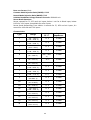
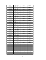
Characteristics:
Accuracy at
25 ˚C
Input
Impedance
Type
Range
J
-120 ~ 1000 ˚C
(-184 ~ 1832 ˚F)
±1 ˚C
3.12MΩ
K
-200 ~ 1370 ˚C
(-328 ~ 2498 ˚F)
±1 ˚C
3.12MΩ
±1 ˚C
3.12MΩ
±1 ˚C
3.12MΩ
T
E
-250 ~ 400˚C
(-418 ~ 752˚F)
-100 ~ 900 ˚C
(-148 ~ 1652 ˚F)
B
0 ~ 1820 ˚C
(32 ~ 3308 ˚F)
R
0 ~ 1768 ˚C
(32 ~ 3214 ˚F)
S
N
L
U
P
W5
W3
LR
A1
A2
A3
M
0 ~ 1768 ˚C
(32 ~ 3214 ˚F)
-250 ~ 1300 ˚C
(-418 ~ 2372 ˚F)
-200 ~ 900 ˚C
(-328 ~ 1652 ˚F)
-200 ~ 600˚C
(-328 ~ 1112 ˚F)
0 ~ 1395 ˚C
(32~2543 ˚F)
0 ~ 2315 ˚C
(32 ~ 4199˚F)
0 ~ 2315˚C
(32 ~ 4199 ˚F)
-200 ~ 800 ˚C
(-328 ~ 1472 ˚F)
0 ~ 2500 ˚C
(-32 ~ 4532 ˚F)
0 ~ 1800 ˚C
(-32 ~ 3272 ˚F)
0 ~ 1800 ˚C
(-32 ~ 3272 ˚F)
-200 ~ 100 ˚C
(-328 ~ 212 ˚F)
±2˚C
(200 ~ 1820
˚C)
±2 ˚C
±2 ˚C
3.12MΩ
3.12MΩ
3.12MΩ
±1 ˚C
3.12MΩ
±1 ˚C
3.12MΩ
±1 ˚C
3.12MΩ
±1 ˚C
3.12MΩ
±1 ˚C
3.12MΩ
±1 ˚C
3.12MΩ
±1 ˚C
3.12MΩ
±1 ˚C
3.12MΩ
±1 ˚C
3.12MΩ
±1 ˚C
3.12MΩ
±1 ˚C
3.12MΩ
25
PT50
(α = 0.00385)
PT100
(α = 0.00385)
PT200
(α = 0.00385)
PT500
(α = 0.00385)
PT1000
(α = 0.00385)
PT50
(α = 0.00391)
PT100
(α = 0.00391)
JPT50
(α = 0.003916)
JPT100
(α = 0.003916)
JPT200
(α = 0.003916)
JPT500
(α = 0.003916)
JPT1000
(α = 0.003916)
Cu50
(α = 0.00426)
Cu100
(α = 0.00426)
Cu50
(α = 0.00428)
Cu100
(α = 0.00428)
Ni100
(α = 0.00617)
Ni200
(α = 0.00617)
Ni500
(α = 0.00617)
Ni1000
(α = 0.00617)
Cu10
(α = 0.00427)
-200 ~ 850 ˚C
(-328 ~ 1562 ˚F)
-200 ~ 850 ˚C
(-328~ 1562 ˚F)
-200 ~ 850 ˚C
(-328 ~ 1562 ˚F)
-200 ~ 850 ˚C
(-328 ~ 1562 ˚F)
-200 ~ 350 ˚C
(-328 ~ 662 ˚F)
-200 ~ 850 ˚C
(-328 ~ 1562 ˚F)
-200 ~ 850 ˚C
(-328 ~ 1562 ˚F)
-200 ~ 600 ˚C
(-328 ~ 1112 ˚F)
-200 ~ 600 ˚C
(-328 ~ 1112 ˚F)
-200 ~ 600 ˚C
(-328 ~ 1112 ˚F)
-200 ~ 600 ˚C
(-328 ~ 1112 ˚F)
-200 ~350 ˚C
(-328 ~ 662 ˚F)
-50 ~ 200 ˚C
(-58 ~392 ˚F)
-50 ~ 200 ˚C
(-58 ~392 ˚F)
-180 ~ 200 ˚C
(-292 ~392 ˚F)
-180 ~ 200 ˚C
(-292 ~392 ˚F)
-60 ~ 180 ˚C
(-76 ~356 ˚F)
-60 ~ 180 ˚C
(-76 ~356 ˚F)
-60 ~ 180 ˚C
(-76 ~356 ˚F)
-60 ~ 180 ˚C
(-76 ~356 ˚F)
-200 ~ 260 ˚C
(-328 ~500 ˚F)
±20mA
±0.4 ˚C
2.0KΩ
±0.4 ˚C
2.0KΩ
±0.4 ˚C
2.0KΩ
±0.4 ˚C
2.0KΩ
±0.4 ˚C
2.0KΩ
±0.4 ˚C
2.0KΩ
±0.4 ˚C
2.0KΩ
±0.4 ˚C
2.0KΩ
±0.4 ˚C
2.0KΩ
±0.4 ˚C
2.0KΩ
±0.4 ˚C
2.0KΩ
±0.4 ˚C
2.0KΩ
±0.4 ˚C
2.0KΩ
±0.4 ˚C
2.0KΩ
±0.4 ˚C
2.0KΩ
±0.4 ˚C
2.0KΩ
±0.4 ˚C
2.0KΩ
±0.4 ˚C
2.0KΩ
±0.4 ˚C
2.0KΩ
±0.4 ˚C
2.0KΩ
±0.1 ˚C
2.0KΩ
-26 ~ 26mA
±0.05%
75Ω
±60mV
-122 ~ 122mV
±0.05%
3.12MΩ
±200mV
-243 ~ 243mV
±0.05%
3.12MΩ
±1V
-1.58 ~ 1.58mV
±0.05%
3.12MΩ
±2V
-3.16 ~ 3.16mV
±0.05%
3.12MΩ
±6V
-6.32 ~ 6.32V
±0.05%
3.12MΩ
±20V
-25.3 ~ 25.3V
±0.05%
3.12MΩ
±50V
-50.6 ~ 50.6V
±0.05%
3.12MΩ
0.4 ~ 2V
-3.16 ~ 3.16V
±0.05%
3.12MΩ
26
1 ~ 5V
-6.32 ~ 6.32V
±0.05%
3.12MΩ
Digital Input Card (DI206):
Channels: 6 per card
Logic Low: -5V minimum, 0.8V maximum
Logic High: 3.5V minimum, 24V maximum
External pull-down Resistance: 1KΩ maximum
External pull-up Resistance: 1.5MΩ minimum
Relay Output Card (RO206):
Channels: 6 per card
Contact Form: N.O. & N.C. (form C)
Relay Rating: 5A/240 VAC, life cycles 200,000 for resistive load
Analog Output Card (AO206):
Channels: 6 per card
Output signal: 4-20mA, 0-20mA, 0-5V, 1-5V, 0-10V
Resolution: 16 bits
Accuracy: ±0.05% of Span ±0.0025% /˚C
Load Resistance: 0-500 ohms (current), 10K ohms minimum (voltage)
Output Regulation: 0.01% for full load change
Output Setting Time: 0.1 second (stable to 99.9%)
Isolation Breakdown Voltage: 1500VAC at 50/60Hz for 1 minute
Integral Linearity Error: ±0.005% of Span
Temperature Effect: ±0.0025% of Span /˚C
COMM Module (IF232 and IF485):
Interface: RS-232 (1 unit), RS-485 or RS-422 (up to 247 units)
Protocol: Modbus Protocol RTU mode
Address: 1-247
Baud Rate: 9.6 ~ 115.2 Kbits/sec.
Measured data Bits: 7 or 8 bits
Parity Bit: None, Even or Odd
Stop Bit: 1 or 2 bits
Standard Ethernet Communication:
Protocol: Modbus TCP/IP, 10/100 Base T
Ports: AUI (Attachment Unit Interface) and RJ-45, Auto- detect capability
Real time clock accuracy vs. temperature inside of housing
Temperature inside housing
10 ~ 40 ˚C
typical error per month
18 seconds
27
0 ˚C or 50 ˚C
-10˚C or 60 ˚C
Environmental & Physical:
52 seconds
107 seconds
Operating Temperature: 0 ~ 50 ˚C
Storage Temperature: -30 ~ 70 ˚C
Humidity: 20 to 90% RH (non-condensing), maximum relative humidity 90% is for
ambient temperature up to 38˚C decreasing linearly to 50% relative
humidity at 50˚C
Altitude: 2000 M maximum
Insulation Resistance: 20 M ohms min. (at 500 VDC)
Dielectric Strength: 2300VAC, 50/60 Hz for 1 minute between power terminal and
earth
Vibration Resistance: 10-55 Hz, 10m/ s² for 2 hours
Shock Resistance: 30m/ s² (3g) for operation, 20g for transportation
Operation Position: no inclined restriction
Dimensions: Panel Mount style: 144(W) x 144(H) x 193mm (D) (for PR10/20)
288(W) x 288(H) x 194mm (D) (for PR30)
Standard Panel Cutout: 137 x 137mm (for PR10/20)
281 x 281mm (for PR30)
Approval Standards:
Safety: UL61010C-1, CSA C22.2 No. 24-93
CE: EN61010-1 (IEC1010-1) over voltage category II, Pollution degree 2
Protective Class: IP 65 front panel for indoor use,
IP 20 housing and terminals
EMC:
Emission: EN61326-1 (EN55022 class A, EN61000-3-2, EN61000-3-3)
Immunity: EN61326-1 (EN61000-4-2, EN61000-4-3, EN61000-4-4,
EN61000-4-5, EN61000-4-6, EN61000-4-8, EN61000-4-11)
28
2. Installation and wiring
2.1
Unpacking
If any damage is found while unpacking, the user should contact the local
representative at once. It is suggested that the special packaging is retained for
possible future requirements.
2.2 Installation
Remove stains from this equipment using a soft, dry cloth. Do not use harsh
chemicals, volatile solvents such as thinner or strong detergents to clean the equipment
in order to avoid deformation.
The recorder is designed for indoor use and not in any hazardous area. It should be
kept away from shock, vibration, and electromagnetic fields such as variable
frequency drives, motors and transformers.
It is intended to operate under the following environmental conditions:
Pollution Degree Level II
Temperature
Humidity
Power
Altitude
IEC1010-1(EN61010-1)
0 ~ 50 ˚C
20 ~ 90 % RH (non-condensing)
90 ~ 250 VAC, 50/60 Hz or 11-36VDC
2000M maximum
29
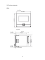
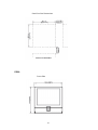
2.3 Panel mounting style
PR10:
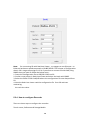
Front Side
Right Side
30
Panel Cut Out Dimensions
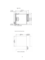
PR20:
Front Side
31
Right Side
Panel Cut Out Dimensions
32
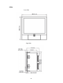
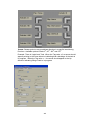
PR30:
Front Side
Right Side
33
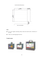
Panel Cut Out Dimensions
Note:
Do not over tighten mounting clamp screws that could result in distortion of
the case.
There is no mounting angle restriction.
Portable styles:
34
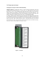
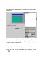
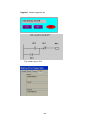
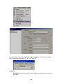
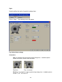
2.4 Setup input and output
Analog input cards (part numbers AI206 and AI203)
AI206 and AI203 are analog input cards in 3 and 6 channels respectively. Each card
includes universal inputs of TC (J, K, T, E, B, R, S, N, L, U, P, W5, W3, LR, A1, A2, A3, and
M), RTD, mV, mA, V. The accepted input types and sensor range for each type are
listed in clause 1.8 of chapter 1. Plug the card into the rear slot then power on. The
recorder will automatically detect the card and display the specific input type, then
show its location in a specific slot when the user is in Configuration Mode.
To select a specific input, please press menu and then the Config button to get into
the configuration window. In the configuration window, press up/down and enter key
to select AI to get into AI setting window. In the AI setting window, move the selected
focus to the item "Type" under the node "Sensor", then press the enter key to select
the desired sensor type. Press OK when finished. All other items are similar to set up.
The item "Events" can be added to do further control.
Figure 2 – 15 (AI206)
35
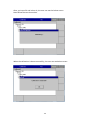
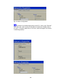
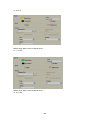
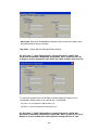
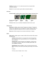
Relay Output card (RO206) / 6 relay alarm card
The relay output card includes 6 relays rated 5 Amp/240 VAC each. Plug the card into
a rear slot and power on the recorder. The recorder will automatically detect the card
and display the output type and its location in a specific slot in System Info mode
while doing the configuration.
To set up the relay output card, please press menu and then the Config button to get
into the configuration window. In the configuration window, press up/down and
enter key to select DO and to get into the DO setting window. In the DO setting
window, the setup steps are similar to AI. The item "Reverse" is to reverse the output
status.
36
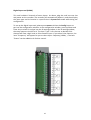
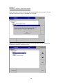
Digital Input card (DI206)
This card includes 6 channels of event inputs. As above, plug the card into rear slot
and power on the recorder. The recorder will automatically detect it, and then display
the input type and its location in a specific slot in System Info mode while doing the
configuration.
To set up the digital input card, please press menu and then the Config button to
get into the configuration window. In the configuration window, press up/down and
enter key to select DI and get into the DI setting window. In the DI setting window,
the setup steps are similar to AI. The item "Type" is for the user to decide if this
channel will have a logic level or Pulse Counter input. If you select Pulse Counter, the
item "Frequency" will appear for you to select input frequency (100Hz, ). The item
"Events" can be added to do further control.
37
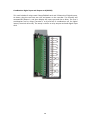
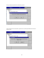
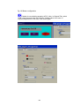
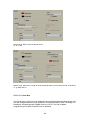
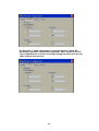
Combination Digital Input and Output card (RD233)
This card includes 3 relays rated 5 Amp/240VAC each and 3 Channels of Digital Inputs.
As above, plug the card into rear slot and power on the recorder. The recorder will
automatically detect it, and then display the input type and also a Relay. The first 3
combination are for relays (Terminal 1 to 9) and last 3 combination are for Digital
inputs (Terminals 10 to 18). The setup is similar to relay output card and digital input
card.
38
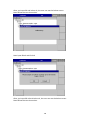
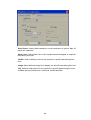
Analog output cards (AO206)
These cards are 6-channel current output cards. They are used to retransmit process
values to other devices like meters, controllers, ect.
To set up the analog output card, please press the menu and then the Config button
to get into the configuration window. In the configuration window, press the
up/down and enter key to select AO. This will get you into the AO setting window. In
the AO setting window, the setup steps are similar to AI. The item "Type" is to decide
whether to output current or voltage. The item "Output" is to select the output range
for current or voltage (0-10, 4-20mA, ect.). The item "Expression" is a math expression
field where the user can input an expression to control the output value.
Note 1: The IO Cards should not be removed or Inserted to the PR
when the Power is ON. This should be carried out in the Power
OFF Condition only.
Note 2: In the PR30, the Analog Input card should be inserted in slots 1
to 8 only. It should not be inserted in slots 9 to 16.
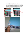
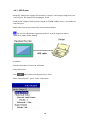
Note 3: The below pictures explain how to install a new AI card into a
recorder slot:
39
Information regarding removing the IO Cards from PR.
For removing the IO Card, First remove the metal screws then plastic
screws, after that press the lock on the top and bottom of the Card and
pull to remove it. Failing to do so will damage the IO Card. Please follow
the below pictures for more information.
The Maximum Torque for the metal screw is 3Kg-cm (2.6in-lb) and the
Maximum Torque for the plastic screw is 0.8Kgf-cm (.7in-lb).
40
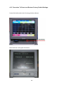
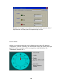
Note 4: For some industries who prefer/favour circular displays, PR30 can offer this
unique feature and set the display speed for each page/circle in 30
minutes, 1, 2, 4, 8, 12 hours, 1, 2 days, or 1, 2, 4 weeks.
Note 5: Calibrate: Sometimes the field calibration is required for high accuracy. In
this case, a qualified engineer can do the necessary calibration.
Note 6: For Thermocouple Inputs, a 1 hour warm up is necessary for
initial set up.
Note 7: Circular Trends are only available for the PR30 mode.
2.5 Wiring of the cards
Wiring Precautions
1. Care must be taken to ensure that the maximum voltage rating specified on the
label is not exceeded.
2. For the panel-mount version, it is recommended that near an external fuse or an
external switch rated at 2A/250 VAC should be used.
3. Beware not to over tighten the terminals screws. The torque should not exceed
0.4 N-m (3.6 Lb-in or 4.0 Kg F-cm).
4. With the exception of the thermocouple wires, all wires should be stranded
copper conductor with maximum gauge of 18 AWG.
5. Connect a grounding conductor with 1.6mm diameter minimum to provide
protective grounding prior to turning on the equipment.
41
Analog Input Card AI206
42
Analog Input Card AI203
43
Relay output card (RO206)
44
Digital input card (DI206)
45
Relay output and digital input card (RD233)
46
Analog output card (AO206)
47
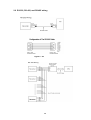
2.6 RS-232, RS-422, and RS-485 wiring
Figure 2 – 24
48
2.7
External Memory Card:
There two types of external storage for the User. One is the SD card and other is USB
memory. There are two slots for inserting USB memory, one in the front and other
on the rear side of the recorder. If bigger capacity USB memory is required, the user
may buy it locally. The SD card slot is in the front side. Please see the below figures
for more information.
Note:
To read measured data and events on USB memory and SD card Memory, it is
necessary to install either the free basic software or the Extensive Data
Acquisition software on PC first.
49
3. BASIC FUNCTIONS OF RECORDERS
In this chapter we will be briefly explaining the functions that are available in the
recorder.
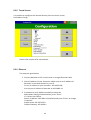
3.1
Configuration
The configuration in the recorder follows a tree type layout. This makes it easy for
users to go through the different sub menus easily and to not miss any setting.
3.2
Standard and Plus Version of Firmware
The standard version of firmware will have only Input configuration, and does not
include Math, External channels, Custom Edited Display, Batch, or FDA CFR part11
functions. However, the plus version includes all the above listed functions.
50
51
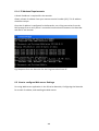
3.3
Communication with Third Party Interfaces
The Recorder has the flexibility to communicate with Third party Interfaces via
protocols such as Modbus TCP/IP or Serial connections as either a Modbus Master
or Modbus Slave. The detailed settings related information can be found in Chapter
4, Configuration, Section 4.5.
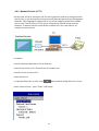
3.4
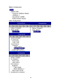
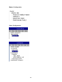
Information Accessibility through WEB
Web Server:
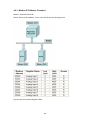
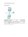
The Recorder Trend and Digital data can be viewed in any place in the world if we
have Web Server connectivity. For this the Recorder should be connected to
Internet with a fixed IP address provided by the Internet Service provider.
Email:
All Important Data events can sent as an email. The detailed settings related
information can be found in Chapter 4, Configuration, Section 4.5.
52
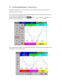
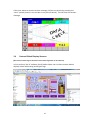
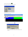
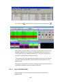
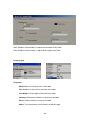
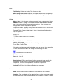
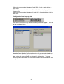
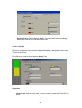
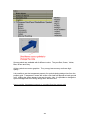
3.5
Handwriting Messages on Trend Screens
Handwriting Messages on Trend Screens is very handy for process associates to
highlight important events.
The User can write handwritten messages using a stylus on Historical Trend screens.
This is shown in the below picture.
When the User navigates through
(Menu) History
Page 1, as
shown in the below screen.
If the User wants to write a message, they can press the pen symbol as shown in the
red square in the screen below
53
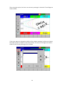
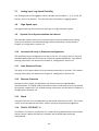
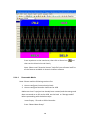
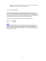
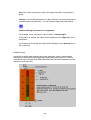
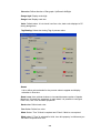
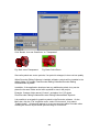
Then using the stylus, the User can write any message in Historical Trend Pages as
shown below.
If the User wants to change the width of the written message, he/she can choose
the width of pen as shown in the screen below. The menu to change the width is
shown by the arrow pointing to the red box.
54
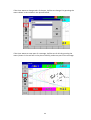
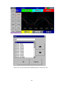
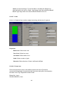
If the User wants to change color of the pen, he/she can change it by pressing the
menu shown in the red box in the picture below.
If the User wants to erase part of a message, he/she can do this by pressing the
menu (shown in the red box in the picture below), and erase part of the message.
55
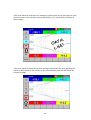
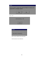
If the User wants to undo part of a message, he/she can do this by pressing the undo
symbol (shown in the red box in the picture below). This will undo the last part of
the message.
If the User wants to delete the written message, he/she can this do by pressing the
delete symbol (shown in the red box in the picture below), and this will delete the
written message.
56
If the User wants to save the written message, he/she can do this by pressing the
“save” symbol (shown in the red box in the picture below). This will save the written
message.
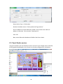
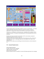
3.6
Custom Edited Display Screens
(We call it a Custom Page on the device and Custom Page Editor on PC software)
In Plus versions, the PC software Panel Studio allows users to have custom edited
displays linked with Analog and Digital Tags.
57
3.7
Analog Input Log Speed Flexibility
The Analog input can be logged at various speeds such as 100ms, 1, 2, 5, 10, 20, 50
Dot/sec and 1 or 2 dot/min. The User has a lot of flexibility in logging speeds.
3.8
High Speed Input
The Digital input can accessed as normal Logic or a High frequency pulse.
3.9
System Clock Synchronization via Internet
The Recorder System clock can be synchronized via internet and Summer Saving
Time can be defined. The detailed settings related information can be found in
Chapter 4, Configuration, Section 4.4.
3.10
Increased Security in Password configuration
The password can be configured as normal or CFR-21. For normal, there is only one
password defined but for CFR-21 three 9 levels of password definition. The related
settings information can be found in Chapter 4, Configuration, Section 4.7.
3.11
Auto Output to Printer
The daily or shift reports data can be printed automatically by a Printer. The related
settings information can be found in Chapter 4, Configuration, Section 4.9.
3.12
External Channels
Besides AI and DI inputs, the Recorders can accept inputs through Modbus
communication. The PR10, PR20, and PR30 can have a maximum of up to 24, 48 and
96 channels respectively. The related settings information can be found in Chapter 4,
Configuration, Section 4.1.6.
3.13
Batch
Using this function, the recorded data can be stored in batches per shift. This makes
it easy for the production personnel, and for quality and quantity management.
3.14
FDA 21 CFR PART 11
This feature is meant to comply with U.S. Food and Drug Administration with human
health concern. When this feature is enabled, the recorded data cannot be
manipulated.
58
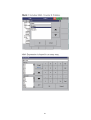
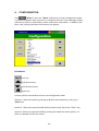
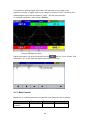
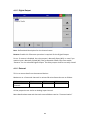
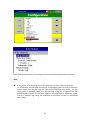
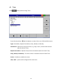
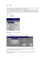
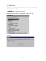
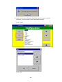
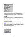
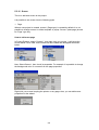
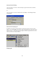
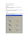
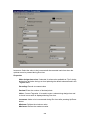
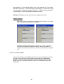
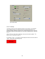
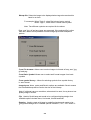
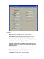
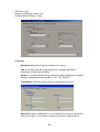
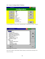
4.
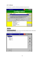
CONFIGURATION
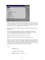
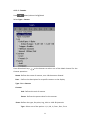
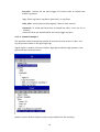
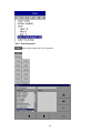
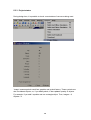
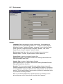
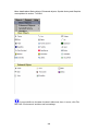
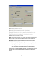
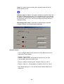
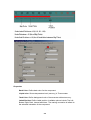
(“Menu”), then the ”More” soft button to enter Configuration mode.
Press
A vertical list appears with a provision to configure Channel, Tools, Message, Display,
Instrument, Security, Auto-Output, Demo, and system Information. In addition, the
Save, Load, Default and Home soft buttons also appear.
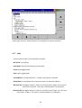
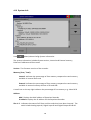
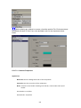
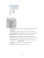
Soft buttons
Enter key
Up directional key
Down directional key
Home key
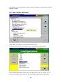
Various options are available to enter into configuration mode
Option-1: Select the mode by pressing up & down directional keys, then press
“Enter” key
Option-2: Select the required mode directly with a touch, then press “Enter” key
Option-3: Select the required mode by pressing the mode two times quickly, it is
same as a double click from a mouse
59
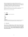
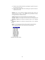
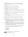
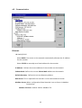
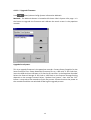
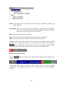
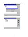
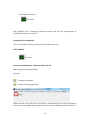
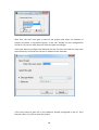
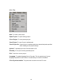
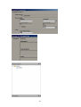
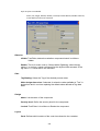
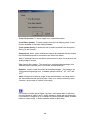
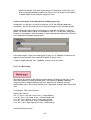
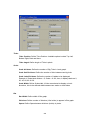
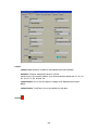
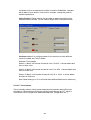
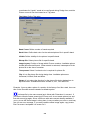
Save: Save configuration from the recorder to a USB Stick or an SD Card.
To read the configuration from a USB Stick for the first time or any time the
configuration has been changed, it is important to press the “Save” soft button to
save configuration changes to the USB Stick or SD Card beforehand.
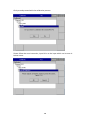
Load: Load configuration from a USB stick or SD Card to the recorder.
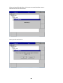
Default: If the configuration is set incorrectly, “Default” is a useful key to recall the
default settings for the analog input card inserted into rear expansion slot.
Home: Returns the User to the home page.
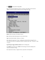
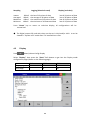
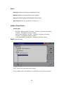
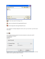
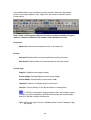
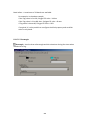
4.1
Path:
Channel
(Menu)-More-Config-Channel
This section is to configure different type of channels. Analog Input (AI), Digital Input
(DI), Math, Analog Output (AO), Digital Output and External device channels.
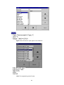
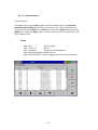
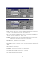
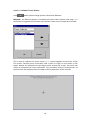
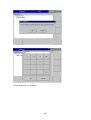
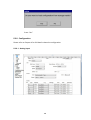
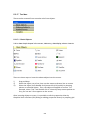
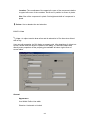
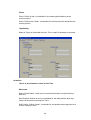
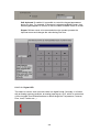
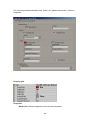
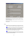
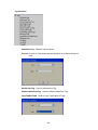
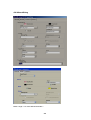
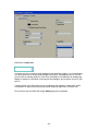
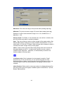
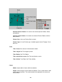
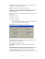
4.1.1 Analog Input
After entering the Configuration mode, in “Channel”, select “AI”, then Press the
“Enter” key to get into Analog Input Channel mode. It displays the Analog input AI1
as the first analog input channel configuration page. Press directional keys〈 〉at
the bottom to select other channels. Press directional keys↑↓ on the right hand
side to select the column. After completing Configuration, press “Back” soft
button, then press “Home” soft button to return to main display. All configurations
will be saved automatically.
60
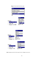
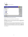
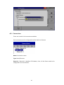
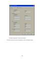
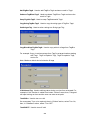
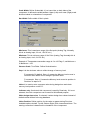
Copy: For example, to copy the channel configuration from channel 1 to channel 2,
select the source channel, in this case AI1 (or whatever the channel is named),
press on “Copy” button. Now, a “Paste” button will get enabled, go to target
channel, say channel 2, and then press on “Paste” button.
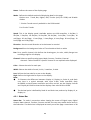
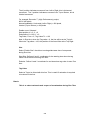
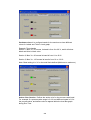
Name: Enables the User to define the name for each channel with a maximum of
18 characters.
Select “Name”, then Press “Enter”, soft button, a keyboard with several keys
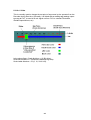
appear. Press “Shift” to select special characters. Press “Caps” to select capital
letters. Press soft key “OK” after entering a new channel name.
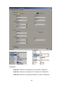
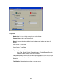
Desc: The description about a specific channel on the display.
Type: Option available to enable or disable the channel from selection
Filter: It is to reduce the noise of input signal before sampling. It is possible to
select range from 1 to 16 sec. It is a soft filter available to reduce fast variation of
analog inputs. It gives a moving average value. For example, if the filter value is set
as 5 sec for AI1, it means all the samples collected in the last 5 sec shall be
averaged, and the value is available to record as per Log method.
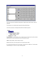
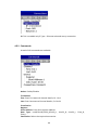
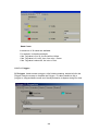
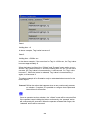
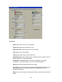
Log:
Data Type: 2 byte
2 byte range: -32767 to +32767
Trigger: Two options are available
61
a) Disable: Select disable while the recording of a specific channel is
not required at this time
b) Enable: Select Enable while the recording of a specific channel is
required at this time
Method: This is the method of logging measured data. Select the
column and press “enter”. Then choose the Log method of Instant,
Average, Minimum or Maximum data.
Instant: logging the last measured data at the sampling interval
Average: logging the averaged measured data at the sampling interval
Minimum: logging the minimum measured data at the sampling
interval
Maximum: logging the maximum measured data at the sampling
interval
Speed: It is the logging speed (recording speed) of measured data.
Select Log Speed column, then choose one of the following
(Auto)Set Jobs under Events
62
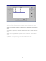
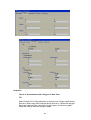
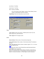
Type: Select the sensor input type for the Channel.
Unit: The engineering unit of input.
63
Range: Select based on Sensor type
Scale: Appears only for linear inputs Ex: mV, Voltage, current etc..
64
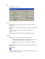
Offset: It is offset value to correct the sensor error.
Gain: It is a multiplier to correct the sensor error.
The correct value = (the process value x gain) + offset
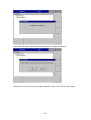
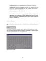
Events
Events are frequently used for Alarm purposes. Events can also be used for digital
outputs (DO), Timer, Totalizer, Counter or Report.
Maximum five events are possible to set for each Analog Input
Press “Add” to add new event
Press “Remove” to remove selected event
Type: There are various types of H, L, HH, LL, Dev+, Dev-, and Error to be selected
for a job
or Alarm purpose
H: High limit. When the process is over high limit, the alarm or job is actuated.
L: Low limit. Any the process is lower than low limit, the alarm or job is
actuated
HH: High high limit, to set up another limit higher than high limit for double
warning.
65
LL: Low low limit, to set up another limit lower than low limit for double
warning.
Dev+: Trigger event on positive deviation of process value. The job or alarm is
activated when process value is deviated by greater than the setpoint+the
process value.
For example:
Set point =10
At 10.00.01 Hrs, Tag1=40
At 10.00.02 Hrs, Tag1 = 51
Then, job or alarm is activated
Dev-: Trigger event on negative deviation of process value .The job or alarm
is activated when the process value is deviated by less than the set point-the
process value.
For ex: Set point =10
At 10.00.01 Hrs, Tag1=40
At 10.00.02 Hrs, Tag1 = 29
Then, job or alarm is activated.
Error: On channel error, an alarm or job is activated
Setpoint: To set up the process value for actuating Job1 and /or Job2
Alarm
Log Alarm: Record alarms
Log Alarm (Auto Ack): Record alarms and acknowledge automatically
Log Event: Record events
Job1, Job2: When an event occurs, the task to be performed is called the job. A
typical example is to trigger an alarm buzzer in the event of a high temperature.
Each pen can accept five different types of events (or alarms) and each event can
create two jobs. Please note that a job under Event is different from a job created
by pressing the Operate key. The former is actuated by an event, and the latter is
actuated by manual control, no event necessary.
Note: Please refer to the section “Jobs” for full details about various jobs
available
Hysteresis: To avoid it been activated too often, the Log Alarm or relay can set for
no reaction. Hysteresis value can be defined for the event trigger set point
66
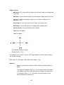
Example1
If the temperature is increased to more than 120 OC, log alarm and switch on digital
output 1. When the temperature is decreased to less than 80 OC, log the alarm and
switch off the digital output1.
Setting of events for the analog input in the channel configuration is as follows..
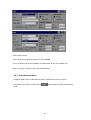
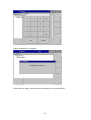
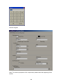
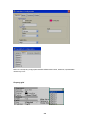
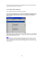
4.1.2 Digital Input
Path:
(Menu)-Config-DI
After entering the Configuration mode, in the Channel, select DI then Press the
“Enter” soft button to get into Digital Input Channel configuration page.
Name: Define the name for the Digital Input Channel. A maximum of 18 characters is
allowed for the name.
Description: Define detail description for the channel.
67
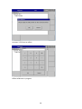
Type: Logic Level
Logic Level: This selection activates digital logic, which is either one or zero with low
frequency which is less than 1Hz, such as an external relay.
Pulse Counter: With this selection, we can feed high speed inputs (high Frequency, up
to 100Hz)
Select Logic Level and press “Enter” key
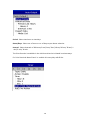
Events: A maximum of 2 events are supported for every digital Input channel.
A maximum of two jobs can be configured for each event.
*Note: Events will not appear if Logic Level selected as Pulse Counter
Add: Press “Add” to add events to the Digital Input
Remove: Press “Remove” to remove events from the Digital Input
Type: Select Low, L or High, H
Job1, Job2: To configure a Job, select Job1, the press the Enter button. It will show a
list of all the available jobs. Select the required Job.
Note: Number of digital inputs shown one t DI screen depends on number of Digital
input cards inserted in the paperless recorder.
Sample applications of Digital input …
After pressing a “Start” switch, latch ON Digital Ouput1
After pressing a “Pause” switch, latch Off Digital Output1
Start Timer, Stop Timer
Reset Totalizer, Reset Counter
Reset MaxMinAve values of all the channels etc..
68
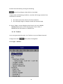
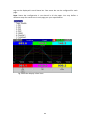
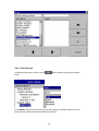
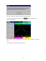
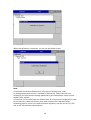
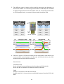
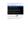
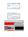
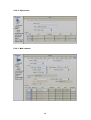
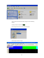
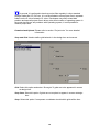
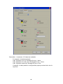
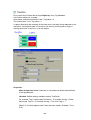
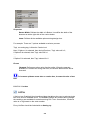
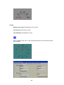
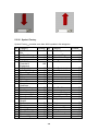
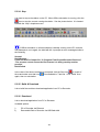
It is possible to display Digital input status via status bar on any page in the
paperless recorder. If digital input is not enabled, it shows as “Low”. Presence of an
enabled digital input shall be shown as “High”. See the picture below.
To configure status bar, refer section “Display”
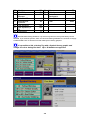
Digital Input status can also monitored from the
(Menu). Press “Status” and
then select “DI”, it will show the Digital Input Status as follows.
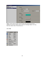
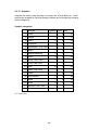
4.1.3 Math Channel
Maximum no. of Math channels in various PR series Recorders are as follows
PR Recorder
Maximum Math
Channels
PR10
15
PR20
40
69
PR30
60
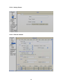
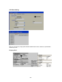
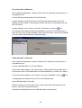
Path:
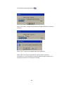
(Menu)-More-Config-Math
After entering the Configuration mode, in Channel, select Math, then Press the
“Enter” soft button to get into Math Channel configuration page.
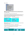
Name: Define the name of the Math channel
Desc: Define the detail description for the channel name
Type: Specify either Math, Totalizer or Counter
Note: Based on selection at “Type”, configuration details will be changed. For ex:
Type=Math has different configuration details compared with Type = Totalizer or Type
= Counter
Log data type, Trigger, Method, Speed: Same as Analog Input
Press Back key and then press “Home” soft button go to Real time display and
memorize the Math settings.
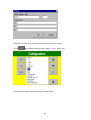
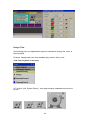
Enter Expression column, it appears Source, Operator and a keyboard.
70
The Source covers all available Analog inputs, Digital Inputs, Math inputs, external
channels.
The Operators are mathematical expressions described below.
Use Source, Operator and keyboard to define the Math equation.
Transformation: Select disable, value or Math channel. This function mainly used to
display process values obtained from Non-linearization table
Table: Select disable, value or Math channel
Maximum 64 rows can be entered in the Transformation table
Ex: A chemical tank has a non-linear shape. The level is 0 to 1400 cms. The Recorder
should display 0 to 170 Tons as per following table
71
Add: Press “Add” soft button to add a new row into the Transformation table
Delete: Press “Delete” soft button to delete existing row from the Transformation
table
Copy: Press to copy existing row in the Transformation table to create a duplicate
entry
Mode: Press to toggle between Input and Output entries in the Transformation
table
Up & Down: To navigate among rows in the Transformation table
72
4.1.3.1 Math Expression
Expressions
Mathematics Functions
+
*
/
SIN(x)
COS(x)
Addition
Subtraction
Multiplication
Division
sin(x)
cos(x)
EXP(x)
SQRT(x)
ex
Square root of x
LN(x)
LOG(x)
ABS(x)
loge(x)
log10(x)
Absolute of x
POW (x,y)
xy
ROUND(x)
The closest integral number to x
HI(x,y)
The bigger value between x and y
INV(x)
TG(x)
1/x
tan(x)
CTG(x)
ASIN(x)
ACOS(x)
ATG(x)
x%y
x^y
1/tan(x)
Sin-1(x)
-1
Cos (x)
-1
Tan (x)
Remainder of x/y
xy
73
4.1.3.2 Math Eample-1
Relative Humidity – PR20 Math application
*How to Calculate Relative Humidity - Theory
Requirement: Two Analog Inputs, Type: RTD
AI1: To measure dry bulb temperature
AI2: To measure wet bulb temperature
First calculate the saturation vapor pressure (E) for both the dry-bulb (Td) and wetbulb (Tw) temperatures using the following equations:
Ew = 0.61078*EXP((17.269*Tw)/(Tw+237.3))*(Td-Tw)
Ed = 0.61078*EXP((17.269*Td)/(Td+237.3))*(Td-Tw)
In the above equations the temperatures units are Celsius and the saturation vapor
pressure units are millibars. The function "EXP" is the exponential and not raising
something to an exponent.
Then calculate actual vapor pressure (Ea) using the following equation:
Ea = Ew-0.63*(Td-Tw)
Relative Humidity is then calculated using the following equation:
RH = (Ea/Ed)*100
The units of relative humidity are in percent.
Here is an example of the using the equations:
Assume that your dry-bulb temperature (Td) = 40 C and your wet-bulb temperature
(Tw) = 30 C.
Ew = 0.61078*EXP ((17.269*Tw)/ (Tw+237.3))*(Td-Tw)
Ew = 0.61078*EXP ((17.269*30)/ (30+237.3))*(40-30)
Ew = 42.4262 millibars
Ed = 0.61078*EXP ((17.269*Td)/ (Td +237.3))*(Td-Tw)
Ed = 0.61078*EXP ((17.269 * 40)/ (40+237.3))*(40-30)
Ed = 73.7416 millibars
Ea = Ew-0.63*(Td-Tw)
Ea = 42.4262 - 0.63*(40-30)
Ea = 36.1262 millibars
RH = (Ea/Ed)*100
RH = (36.1262/73.7416)*100
RH = 48.99 %
74
* End of Theory
5 Math channels are required to calculate one RH.
Td = AI1, analog input for dry bulb temperature (PT100)
Tw =AI2, analog input for wet bulb temperature (PT100)
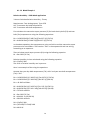
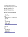
Math1 = EXP ((17.269*AI1)/ (AI1+237.3))
Math2 = Ed1 = 0.61078*Math1*(AI1-AI2)
Math3 = EXP ((17.269*AI2)/ (AI2+237.3))
Math4 = Ew1 = 0.61078*Math3*(AI1-AI2)
Ea = Ew - 0.63 * (Td - Tw)
Math5= RH1 = ((Math4-0.63*(AI1-AI2))/Math2)*100
75
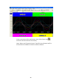
Now, in Math5, you will get Relative humidity in %
Five events are supported for every Math channel and two jobs are available in
every event, the same as the Analog input channel.
Math channels are virtual channels. They contain measured values based on
equations. These values can be recorded similar to physically connected Analog
inputs and display digital values, trends, bar graphs etc.
76
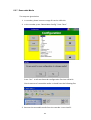
4.1.3.3 Counter
Path:
(Menu)-More-Config/Math
Select Type = Counter
Press directional keys〈 〉at the bottom to select one of the Math channel for the
Counter operation.
Name: Defines the name of counter, max. 18 characters allowed
Desc: Defines the description for a specific counter on the display
Type: Select Counter
Counter
Unit: Defines the unit of counter
Preset: Defines the preset value for the counter.
Event: Defines the type, Set point, Log, Job1 or Job2 & Hysteresis
Type: Select one of the options: H, L, HH, LL, Dev+, Dev-, Error
77
Set point: Defines the set point trigger of Counter value to initiate Jobs
and/or Log alarms
Log: Select Log Alarm, Log Alarm (Auto Ack.), or Log Event
Job1, Job2: various jobs can be assigned, 2 jobs for each counter
Hysteresis: To avoid jobs have been activated too often, it can set for no
reaction.
Hysteresis value can be defined for the event trigger set point
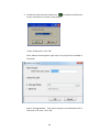
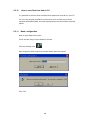
4.1.3.4 Counter Example-1
The operator wishes to know the number of occurrences of an event in a day. Let’s
say the pressure switch in DI1 goes logic high
Digital input1 is used for a Pressure switch. High signal indicates High pressure, Low
signal indicates normal pressure
(Reset Counter1 historical data in order to log new data for the next day)
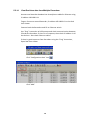
78
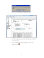
Archive historical data by pressing the following.
(Menu)-Event-Report, Select Daily in the Mode
If values meet the following conditions, recorder will change notation from
traditional to scientific
a. the value is more than 10^5 or less than 1/(10^5)
b. the value digit-length in display exceeds the allowed range
Ex: Up to 5 digits, counter displays value directly, let’s say 0-99999.
100000 will be shown as 1E5, which means 5 zero’s after 1
4294967295 will be shown as 4.29497E9 etc.
4.1.3.5 Totalizer
In our new generation Recorder, the Totalizer is a part of Math channels.
Configuration Path:
(Menu)-More-Config-Math
Select Type = Totalizer
79
Press directional keys〈 〉at the bottom to select from available Totalizers
Name: Defines the name of the Totalizer, Maximum 18 characters allowed
Desc: Defines the description for a specific Totalizer on the display
Type: Select “Totalizer”
Log: Same as Analog input configuration
Totalizer:
Input: Analog Input (AI) or Pulse Counter (DI)
Source:
Select
the
source
input/Math/Counter/Totalizer
for
the
Totalizer
from
Action: Disables or enables the Totalizer
Decimal: Defines the decimal point for the Totalizer
Period: Selects if seconds, minutes or hours are used for the Totalizer
Unit: Defines the unit of totalizing
Preset: Defines the preset value for the Totalizer.
80
Analog
Low Cut: Defines the Low Cut for the Totalizer.
For ex: If 0.0 is set as Low cut, then, if source channel AI1 is less than 0.0, the
Totalizer value will not go to negative.
Event: Total 5 events are supported for each Math channel. Defines the
type, Set point, Log, Job1 or Job2 & Hysteresis
Type: Select one of options, H, L, HH, LL, Dev+, Dev-, Error
Set point: Defines the set point trigger of Totalizer value to initiate Jobs
and/or Log alarms
Log: User can select one of Log Alarm, Log Alarm (Auto Ack.), or Log Event
Job1, Job2: various jobs can be configured, 2 jobs for each Totalizer
Hysteresis: To avoid jobs from being activated too often, the hysteresis can
set to avoid nuisance tripping. Hysteresis values can be defined
for the event trigger set point
4.1.3.6 Totalizer Example-1
Water flow rate is in M3/Sec. The operator wants to know about total water
discharged and wants this information in daily, weekly and monthly reports
81
Reset Totalizer1 historical data in order to log new data for the next day
Archive historical data by pressing the following.
Path:
(Menu)-Event-Report
Select Daily in the Mode to see reports on daily basis. To navigate to another
day, press on Left and right arrows below the Mode button. Select Weekly in
the Mode to see weekly reports, or select Monthly on the Mode to see
Monthly reports.
82
4.1.4 Analog Output
After entering the Configuration screen, in the Channel section, select AO, then Press
the “Enter” soft button to get into Analog Output Channel configuration page.
Desc: Define detail description for the channel name
Type: Current, Voltage
Output: Select either disable, 0 to 20mA , 4-20mA, 0-5V, 1-5V, 0-10VDC
Expression: This is similar to Math channel.
83
4.1.5 Digital Output
Desc: Define detail description for the channel name
Reverse: Enable this if Reverse operation is required for the Digital Output.
For ex: If reverse is disabled, the relay output is Normally Open (NO). In case if you
need to have a Normally Closed (NC) relay at Recorder Power ON, then enable
“Reverse” for the selected Digital Output. The Relay output shall be normally closed.
4.1.6 External
This is to access data from the external devices.
Maximum no. of external channels in various PR series Recorders are as follows
PR Recorder
Maximum External
Channels
PR10
24
PR20
48
PR30
96
All the properties are similar to Analog Input channel.
More details about external channels are available at section “Communication”
84
Please refer section “Communication” for examples of external channels
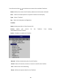
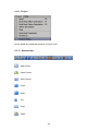
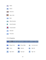
4.1.7 Jobs
Various types of jobs can be selected as follows.
No Action: Do nothing
Send Email: Send Email directly from Recorder
Pause: Stop logging data.
Start: Start logging data.
Sound Buzzer: Sound the buzzer. It stops once any key is pressed.
Dump Data: To dump data from internal memory to external memory.
DO Latch On: Set digital output / relay on, and then select Target, let’s say from
one of DO 1 to DO 6. The relay is latched when it is activated.
DO Latch Off: Set digital output / relay off, and then select Target, let’s say from
one of DO 1 to DO 6. The relay is un-latched when it is activated.
85
DO Process: Set digital output / relay on for process high or low, and then select
the target, let’s say from 1 of DO 1 to DO 6. The relay is not going to be latched
when it is activated.
Enable Timer: Start the timer, and then select Target timers
Disable Timer: Stop the timer, and then select Target from Timers
Preset Totalizer: set a preset value to the target Totalizer.
Reset Totalizer: Reset Totalizer to zero. Select a single Target Totalizer or All totalizers
Enable Totalizer: Starts the Totalizer. Select a single Target Totalizer or All totalizers
Disable Totalizer: Stops the Totalizer. Select a single Target Totalizer or All totalizers
Preset Counter: set a preset value to the target counter.
Reset Counter: Resets the counter to zero. Select a single Target counter or all
counters
Inc Counter: Increases the counter by 1. Select a Target counter or all counters
Dec Counter: Decrease the counter by 1. Select a Target counter or all counters
Log Report: Make a report for Counter, Totalizer, Analog inputs (Min/Max/Avg),
Math (Min/Max/Avg), All Counters, All Totalizers, and All Channels
(Min/Max/Avg). Choose this column, and the report will be presented as
described in section “Reports”.
Reset MinMaxAve: In the Report function, after logging the Min/Max/Avg data of
AI and Math channels for one day for example, this will reset historical data in
order to log new data for the next day. It is also possible to reset the
Min/Max/Avg for “All Channels” at one step.
Print: If a printer is connected to the Paperless Recorder via the USB port or
Ethernet, the following print jobs can be triggered from “events”
Print Historical data
Print Event List
Print Report List
Print Snapshot
The time period of Print depends on the configuration available at
(Menu)-More-Config-Auto-Output
86
Note: Please refer section “Auto Output” for more details about options available
Note:
In any mode , the sampling rate of the recorder is fixed at 100 milli seconds,
i.e. 10 samples are collected per second. If the logging speed is set at 1 second in
Instant mode, the recorder logs the last of ten measured data values. For the
same speed in Average mode, the recorder logs using the average of the Ten
measured data values. For the same speed in the Maximum or Minimum mode,
then the recorder logs using the maximum or minimum of the Ten measured
data values.
87
Sampling
Instant
Averaged
Maximum
Minimum
Logging (historical trend)
100mS the last of 10 points of data
100mS the average of 10 points of data
100mS the maximum of 10 points of data
100mS the minimum of 10 measured data
Display (real time)
last of 10 points of data
last of 10 points of data
last of 10 points of data
last of 10 points of data
Press “Home” key to return to real-time display, all configurations will be
memorized
◆ The Digital output DO card with relays can be set in Job1 and/or Job2. It can be
viewed in “System Info” mode after it is installed into a Slot.
4.2
Path:
Display
(Menu)-More-Config-Display
Select “Display”, then press the “Enter” Soft button to get into the Display mode
configuration page (shown on the following page).
Display pages
Pens/Page
PR10
8
6
PR20
20
6
88
PR30
21
10
Name: Defines the name of the display page
Mode: Defines the default method of displaying data for the page.
Options are: Trend, Bar, Digital, Mix, Circular (only for PR30) and Disable
modes.
* Circular Trends are only available in the PR30 model.
For Circular Trends
Speed: This is the display speed. Available options are 100 msec/dot, 1 Sec/dot, 2
Sec/dot, 5 Sec/dot, 10 Sec/dot, 20 Sec/dot, 30 Sec/dot, 1 min/dot, 5 min/dot, 10
min/Page, 30 min/Page, 1 hour/Page, 2 hour/Page, 4 hour/Page, 8 hour/Page, 12
hour/Page and 1 Day/Page.
Direction: Sets the trend direction to be horizontal or vertical.
Background: Sets the background color of Trend mode to black or white
Pen: For a specific channel, this defines the drawing pen, its color, width, Range Low
and Range High for the display.
Channel: Selects a specific analog input, Math, Counter, Totalizer, External
channels. Select Disable if a specific channel is not required to be displayed.
Color: Selects the color for each pen.
Width: Selects the width of trend, 1-thin, 2-medium, 3-wide.
Low: Defines the low scale for a pen on the display.
High: Defines the high scale for a pen on the display.
Note:
◆ To illustrate the difference between Display Hi, Display Lo, Scale Hi, and Scale
Low, here is a typical example, with input 0-10V, Scale Low=0.00, Scale
Hi=100.00, to have better resolution and vision on Bar, set the Display Lo=0.00
and Display Hi=50.00 so that the Bar displays from value 0.00 to 50.00.
◆
The decimal point is defined by Scale Hi and Scale Low, and not by Display Hi, or
Display Lo.
4.2.1 Status Bar
Status Bar: To make it convenient when viewing the status of Digital Input, Digital
Output, Math channel, Totalizer, Counter and AO, the user may enable these items in
the status bar. The Status bar is displayed at Lower part of the page. A maximum of 10
89
tags can be displayed in each Status bar. One status bar can be configured for each
page.
Note: Status bar configuration is not shared in all the pages. You may define a
different setup for status bars in each page per your requirements.
Fig: Status bar display in Real time
90
4.3
Path:
Timer
(Menu)-More-Config-Timer
Press directional keys〈 〉at the bottom to select from one of 20 available timers.
Type: Countdown, Repeat Countdown, Daily, Weekly or Monthly.
Countdown: Defines the interval of time, e.g. days, hours, minutes and seconds.
(Not the Actual Time)
Repeat Countdown: Repeats the previous countdown (Not the Actual Time)
Daily, Weekly or Monthly: The timer works in selected interval of Real Time.
Action: Disables or enables the timer.
Job1, Job2: 2 jobs can be configured for each timer.
91
4.3.1.1 Timer Example-1
Switch on water pump every day at 8.00am and switch off at 10.00am
This application requires a “Daily” timer which works with Real Time Clock.
Configuration settings are as follows.
Timer1
Type: Daily
Action: Enable
Time – Hour: 8 Min: 0 Sec: 0
Job1: DO Latch On, Target: DO1
Job2: No Action
Timer2
Type: Daily
Action: Enable
Time – Hour: 10 Min: 0 Sec: 0
Job1: DO Latch Off, Target: DO1
Job2: No Action
4.3.1.2 Timer Example-2
Let’s say, when a digital input high event is triggered by high pressure, you would
like to switch on a relay after a 10 seconds delay.
Digital Input1
Event1
Type: H
Job1: Enable Timer, Target: Timer1
Job2: No Action
Event2
Type: L
Job1: DO Latch Off, Target: DO1
Job2: No Action
Timer1
Type: Countdown, Action: Disable
Time – Hour: 0 Min: 0 Sec: 10
Job1: DO Latch On, Target: DO1
Job2: No Action
92
4.3.1.3 Timer Example-3
Timer & Report:
A manager plans to get a daily report from the recorder about the minimum,
maximum and average values of the process every day. After production has
finished, he can press Menu, then Event, then he selects Report and presses the
Mode key to select the Daily mode. He then is able to view the report like in the
figure shown below
Timer1
Type: Daily
Action: Enable
Time – Hour: 17
Min: 01
Job1: Log Report
Target: ALL CH MinMaxAve
Job2: Reset Min/Max/AveTarget: ALL CH
(Reset historical data in order to logging new data for the next day.)
93
4.4
Path:
Clock
(Menu)-More-Config-Clock
Fig: Clock configuration page in Paperless Recorder
Date Style: Selects either month/date/year or date/month/year
Date/Time: Set up the local time. Use directional keys Up/Down to select the column,
press “Enter” soft button to change the clock data. Then press the “Apply Time” Soft
button to apply it to the recorder.
Summer time: In some countries of North America and Europe, clocks are adjusted
forward one hour near the start of spring and are adjusted backward in autumn. This
is commonly referred to as Daylight Savings Time. We refer to this as “Summer Time”.
A Summer time set provision is available in the paperless recorder. In Summer time,
Select Type: Enable and then set Start (Month, Day, Hour, Min) and End (Month, Day,
Hour, Min) details.
94
4.5
Communication
Ethernet
IP: DHCP/STATIC
Select DHCP if the server on the network automatically allocates the IP address
for the recorder.
Select STATIC to manually set a fixed address for the recorder.
IP Address: Defines the current address of the recorder on the network
Subnet Mask: Defines the current Subnet Mask address on the network
Default Gateway: Defines the current Gateway address.
DNS Server: This is required if the recorder is to be connected to Internet
Modbus Server: When configured as Slave Recorder is act as Server in Modbus
Connectivity
Modbus TCP Port: Default: 502 for Modbus TCP
95
Serial:
Protocol: Modbus RTU Master/ Modbus RTU Slave
Address: Address of Master/Slave in the network
Baud rate: 9600/14400/19200/38400/57600/115200
Data format: None, 8, 1 or Odd, 8, 1 or Even, 8, 1
Modbus Client/Master:
Sample Rate:
Ethernet: 100 msec/dot, 1 sec/dot, 2 sec/Dot, 5 sec/dot, 10 sec/dot
Timeout : The default timeout is 100ms
Serial: 100 msec/dot, 1 sec/dot, 2 sec/Dot, 5 sec/dot, 10 sec/dot
Timeout : The default timeout is 100ms
Interval between 2 commands : The default timeout is 10ms
Email: Enable/Disable
Press’ “Email Test” and check mail function
If any problems with Email delivery, it will show error as shown attached
96
4.5.1 Connections
There are a total of 16 connections available
Each connection can be configured as either Serial or Ethernet
Name: Connection name
Type: Serial/Ethernet
Slave ID: If Recorder is Modbus RTU Master, then, all the Slaves need to be
configured in the connections.
97
IP: This is enabled only if Type = Ethernet selected at any connection
4.5.2 Commands
A total of 16 commands are available
Action: Enable/Disable
To Channel:
First: Enter first external channel details, Ex : Ext1
Last: Enter last external channel details, Ex: Ext24
From Device
Register:
Start: Address: Enter Start register address
Data Type: Int16/Uint16/Int32_B/Int32_L, UInt32_B, UInt32_L, Float_B,
Float_L
Connection: Select the required connection
98
4.5.3 Modbus RTU Master, Example1
Master: Paperless Recorder
Slaves: External IO modules, 2 nos. each with 8 channel Analog inputs
Fig: External IO modules Register table
99
Master Configuration
Slave Configuration
100
4.5.4 Modbus RTU Master, Example2
Master: Paperless Recorder
Slave: PID Controller
Fig: External PID Controller Register table
101
Master Configuration
Slave Configuration
102
4.5.5 Modbus RTU Slave, Example
Master: PC, Modbus RTU OPC Server
Slaves: Paperless Recorders, 2 nos. each with 6 channel Analog inputs
103
Fig: Paperless Recorder (Slave) Register table and scaling information
104
4.6
Instrument
Language: A total of 20 languages are supported. They include English, Simplified
Chinese, Traditional Chinese, Japanese, Korean, French, German, Italian, Polish,
Spanish, Portuguese, Brazil Portuguese, Russian, Thai, Czech, Danish, Dutch, Swedish,
Turkish & Greek.
Security: Select Normal or CFR-21 security.
“Security”
More details available at section
Batch Control: Disable and Enable options available for the selection. Refer section
“Batch Control” for more details.
Volume: When the screen is touched, you can hear a “beep” sound. Select Disable to
switch off the beeper. Select value 1 to 10 for volume control. 1 is minimum sound
and 10 for maximum sound
Tool bar: On left side of the display page, the tool bar appears for configuration.
Auto Hide: Select 10 Sec or 20 Sec or 30 Sec or 60 Sec to hide the tool bar if the user
does not operate recorder via touch screen for the set time interval. Select “disable”
if auto-hide is not required on specific set time
Scan Page: The User can set Automatic scanning of display pages for fixed time
when enabled . The Fixed times are 1minute to 10 minutes.
Idle time: If touch screen is not used for the set idle time, then the display pages will
start scrolling as per defined scan rate. Select 1 to 10 Min. for the idle time if display
scroll feature is required, otherwise select “disable”.
105
Scan Rate: This is the scroll time for the display pages. Select a time interval between
5 sec to 30 sec. This time interval is effective only if the “idle time” is enabled and the
selected time is between 1 to 10 min
LCD:
Brightness: Select level between 0 and 6. 0 is the lowest brightness and 6 is for the
highest possible brightness
Screensaver: To prolong the life of the LCD display, it is suggested to set the display
turn-off time to 1, 10, 20, 30, 40, 50 or 60 minutes after the last time the user
operates the recorder. Screensaver default time is set to 10minutes from the factory.
The recorder continues to record data while it is in screen saving mode. The display
turns on again by touching the LCD screen
Storage: Select internal flash memory or SD card
Custom page: User can use this setting to enable or disable custom pages
downloaded via Ethernet.
Allow download via Ethernet: Enable/disable
4.7
Security
4.7.1 Normal
Path:
(Menu)-More-Config-select Instrument, then press “Enter”
Select “Security” = Normal
If normal security is selected, users will need to key in a common password with a
maximum of 18 characters. Once the password has been entered, the user needs to
key in the password whenever Config, Dump, Clear or Operate soft keys are required.
These keys enable the user to do configuration, dump data, clear data or manually
operate the job. For easy access Config, Dump, Clear or Operate soft keys, the user
may ignore the password by leaving the password field blank. If a password is not
entered initially, there is no password required.
How to enter simple password
(Menu)-More-Config, select Password, press “Enter”, then key-in the passwor
106
4.7.2 CFR-21
If the higher security CFR-21 is selected, it requires the recorder to operate with more
restricted rules which comply with FDA 21 CFR Part 11
It has time limit during operation. If the user does not press ay keys in a predefined
period of time (which can be selected between 1 to 20 minutes using LogOut
function), the user needs to key in the password again. It also offers an audit trail
function to record the user, the timing, and what type work the user was doing on the
recorder. Incorrect password and unauthorized operation will be recorded into the
event list as well.The maximum number of users available in FDA 21 CFR Part 11
Security Mode is 30.
In
(Menu)-More-Config-Select Instrument, press “Enter” soft button.
Select Security = CFR-21.
LogOut: Time selection available from 1 min. to 20 min. This selection is visible only if
CFR-21 is selected
If no user operates the Paperless Recorder for the above set duration, the current
user will be logged out automatically
Password validity:
Password validity can be set for 30, 60 or 90 days. After the preset amount of days, it
will require the user to key in a new password, or keep the old one for an additional
30, 60 or 90 days.
Security levels:
0 to 9 levels are supported
9 is the highest authority level, 0 is the lowest
107
4.8
Demo
The Demo mode is a simulation mode used as a sales tool for demonstration purposes.
It is set to simulate AI analog inputs and Math functions.
To start the automatic demonstration, first enable Demo mode, then turn the power
OFF and Power ON to make it effective. To stop the automatic demonstration and
return to real mode with real inputs, first disable Demo mode, then turn the power off
and Power ON.
4.9
Auto-Output
Setup Printer: It is to configure printer
Select Setup Printer and then press the “Enter” soft button
Two kinds of printers are supported. One is USB printer for page printing and
another is Serial printer for Line printing
Applications: Print Historical data, events, & Reports and snapshot directly from
Paperless Recorder.
108
4.9.1 USB Printer
Generally, USB printer support PCL protocol. It means, it will support Page Print, but
not line print. We support PCL language 4, 5 & 6
If USB printer supports ESCP protocol similar to EPSON LQ300+, then, it is possible to
take line print.
Please refer Printer user manual for exact protocol details
Do not use USB printer supporting only PCL to print single line alarms,
otherwise, pages will be wasted
Procedure
Connect Recorder to Printer via USB cable
Power ON Printer
Path:
(Menu)-More-Config-Auto-Print, Enter
Select “Setup Printer”, press “Enter” soft button
109
Printer: PCL Laser, ESCP printer, PCL Inkjet available by default. Select one from the
list as per printer model connected to the Paperless Recorder
Port: It shows “Network” by default. Once a printer is connected to the USB port, it
will show “LPT1” for the USB printer. Select “LPT1”
Net Path: It is required to enter the correct network path here only if both Printer
and Paperless Recorder are connected to a LAN network
Paper Size: A4, B5, Legal and Letter are supported
Draft mode: By default, it is selected. If more quality print is required, deselect Draft
Mode
Color: Enabled for Inkjet printer
Orientation: Select Portrait/Landscape as per requirements
Note: Margins & Print Range are not working at this time.
Now, setup is ready at Paperless Recorder
110
4.9.2 Network Printer (LPT1)
Serial printer will print minimum one line and is generally used for printing Real time
alarms. Also, it can be used for printing historical data and alarms from the Paperless
Recorder. ESCP language id supported, so any printer supporting ESCP like LQ300+
can be used. The LPT1 port of a PC can be connected to a Serial printer directly.
However, it needs to have a Printer driver installed in PC first, and share it for
network use via Ethernet.
Procedure
Connect Paperless Recorder to PC via Ethernet
Install Printer driver in PC. Share Printer for network use
Connect Printer to PC via LPT1
Power ON Printer
In Paperless Recorder, at Path, select
(Menu)-More-Config-Auto-Print, Enter
Select “Setup Printer”, press “Enter” soft button
111
Select ESCP printer.
Then, enter the proper Net Path. Ex: \\PC1\LQ300
PC1 is computer name and LQ300 is shared printer driver for network use
Now, the setup is ready at the Paperless Recorder
4.9.3 Print Historical data
Configure USB Printer or Network printer as explained in earlier section
(Menu) -More-Config-Auto-Output,
In Paperless Recorder, at Path, select
Enter
112
Period: Select Last hours or Last days
Hours/Days: Select no. of hours or no. of days as per above selection
Interval: Select intervals of 100 msec/1 sec/2 sec/ 5sec/ 10 sec/ 20 sec/ 30 sec/ 1
min/ 5 min/ 10 min.
The Print function is available in the Job list and can be initiated in various ways.
Ex: Print historical data of last 1 hr. and do this every day at 8.00 hrs
113
4.9.4 Print Reports
In Paperless Recorder, at Path, select
Enter
(Menu)-More-Config-Auto-Output,
In the Mode, select which kind of Reports are required. Available options include
Daily Reports, Weekly Reports and Monthly Reports
114
4.9.5 Print Snapshot
(Menu)-More-Operate-Print Snapshot
115
4.10 System Info
Path:
(Menu)-More-Config-System Information
The system information includes System version, Internal and External memory,
Ethernet IP address and Slots status
Version: The firmware version of the recorder.
Memory (Free / Total):
Internal: Indicates the percentage of free memory compared to total memory
available in internal flash card
External: Indicates the percentage of free memory compared to total memory
available in external memory devices of SD and USB.
A small icon on the top right indicates the percentage of free memory e.g.: Mem 96 %
Address:
MAC: Displays the MAC address of Paperless Recorder
IP address: Displays the IP address for the Paperless Recorder
Slot 1..5: Indicates the status of all Slots and the cards that have been inserted. The
cards include Analog Input AI, Digital Input DI and Digital Output DO & AO.
116
4.10.1.1 Upgrade Firmware
Path:
(Menu)-More-Config-System Information-Maintain
Maintain: The Maintain button is located at left lower side in System Info. page. It is
the button to upgrade the firmware and calibrate the touch screen in the paperless
recorder
Upgrade Core System:
This is to upgrade firmware in the paperless recorder. Contact factory/supplier for the
latest firmware files. Please download firmware file to a USB stick or SD Card then,
insert the USB stick into USB port or SD Card at SD card Slot in the Paperless Recorder.
Select the External Storage to SD Card or USB flash on the External Storage Setting
depends on the storage inserted. Select “Update Core System”, then click the “OK”
button. It may take a few seconds to finish the process. Please note that the power to
the recordershould be not switched off during this upgrade process
117
4.10.1.2 Calibrate Touch Screen
Path:
(Menu)-More-Config-System Information-Maintain
Maintain: The Maintain button is located at left lower side in System Info. page. It is
the button to upgrade the firmware and Calibrate touch screen in paperless recorder
This is used to calibrate the touch screen. A “+” symbol appears in the center of the
LCD screen. Carefully press and briefly hold a stylus or finger on the center of the
target. Repeat this procedure as the target moves around the screen. Just touch the
screen to complete the screen calibration. This procedure helps to locate pointer via
touch screen and properly select the objects during operation of the recorder
118
4.11 Batch Control
This feature is to store data in a different folder for every batch and archive data
later with reference to a batch.
Path:
(Menu) - More-Config- Instrument
Select Batch Control and press “Enter” key. Select “Enable”. Press “Ok”
Press “Back”
119
Press “OK”, then, press “Home” Soft key to save these settings
Power the recorder OFF then ON, then in the
will be shown as below
(Menu), the Batch soft key
Note: “Batch” soft key will appear only after Batch Control enabled as explained
above
Press on Batch and it shows the following screen
120
Operator can enter a maximum of three comments for any batch.
In the
(Menu)-More-Config, select “Batch”, press “Enter” key
It will show the Batch control settings as shown below
121
Name: Enter Batch name. A maximum of 18 characters is allowed. By default, the
name is Batch1.
Lot Number: Enter the Lot number. If Auto increment is enabled, then Lot numbers
will be incremented automatically by the recorder, Batch1-1, Batch1-2,
Batch1-3 etc. during every start of a new batch
Jobs: Two events, Start, Stop are available
Start: Start means Jobs that should be done during start of a new batch
Stop: Stop means Jobs that should be done during stop of a batch
Note: When batch control is enabled, the recorder will be in Pause mode by default
initially and it requires Starting of the recorder from the Menu by pressing at
(Menu) - More than “Start”. When recorder is not logging any data, Pause
status shall be shown in the Top right area of the recorder as shown below
How to do the batch control
Press on
(“Menu”), “More”, then “Start”. Batch number will be shown in the
recorder Top area.
To Stop this batch, press on “Menu”, “More”, then “Pause”. It gives a message
“Saving data” and updates batch data in the internal memory of the paperless
recorder.
122
4.11.1.1 Batch Example-1
The operator wants to start a batch every day at 8.00am and stop the batch at
12.00am.
Configuration
Timer1
Type: Daily
Time – Hour: 8
Job1: Start
Job2: No Action
Action: Enable
Min: 0 Sec: 1
Type: Daily
Time – Hour: 12
Job1: Pause
Job2: No Action
Action: Enable
Min: 0 Sec: 1
Timer2
How to view batch data in Recorder
Press on
(Menu)-History-Page1
Press “Search”, select required Batch and press “Ok”
Batch details including lot number can be archived by pressing soft key “Batch”
123
124
How to Dump Batch data to external USB memory
Press on
(Menu)-More then press on Dump
Select “All” or required lots and press “OK”
125
For ex: Batch1-1, Batch 1-2, Batch1-3 are available
Initial 1 Lot means, Batch1-1
Initial 2 Lots means, Batch1-1 and Batch1-2
Initial 3 Lots means, Batch1-1, Batch1-2 and Batch1-3
Note: Provision not available to dump only specific lot.
Please refer Instrument->Data Transfer-> Transfer and Remain
Press on “Yes” to dump data from internal memory to external SD Card or USB
memory.
If you have 3 batches, let’s say Batch1-1, Batch1-2 and Batch1-3, then you can see
three different folders in the external USB memory card after completing of dump
Please note that the data available in USB memory is in a proprietary format to avoid
any kind of tampering. You will need PC software to view this data.
126
4.12 Calibrate
This function is used for calibrating Individual Analog channel.
Example 1:
Calibrate an AI with 0-5V
When you click Calibrate menu, the user can see the below screen. Please click
calibrate as shown in the below screen
127
Please note that , Inorder to calibrate the whole Module slot accurately , the 3rd
channel of each slot nust be calibrated first. Click OK.
Now click Calibrate button as shown below.
128
Click yes and proceed with the calibration process
Please follow the next instruction, input 0V in to the input which can be seen in
below screen
129
After you input 0V and select ok, the user can see the below screen.
Now follow the next instruction.
Now input 5V and click ok
130
After you input 5V and select ok, the user can see the below screen
Now follow the next instruction.
When the calibration is done successfully, the user can see below screen.
131
Example 2:
Calibrate an AI with K-Type Thermocuple
Please note that , Inorder to calibrate the whole Module slot accurately , the 3rd
channel of each slot nust be calibrated first. Click OK.
When you click Calibrate menu, the user can see the below screen. Please click
calibrate as shown in the below screen
132
Click yes and proceed with the calibration process
Please follow the next instruction, input 0 mV in to the input which can be seen in
below screen
133
After you input 0V and select ok, the user can see the below screen.
Now follow the next instruction.
Now input 60mV and click ok
After you input 60 mV and select ok, the user can see the below screen
Now follow the next instruction.
134
When the calibration is done successfully, the user can see below screen
135
Calibrate an AO with 4-20mA
When you click Calibrate menu, the user can see the below screen. Please click
calibrate as shown in the below screen
Click ok and proceed and select the channnel of Analog Output to be calibrated.
136
Confirm the channel to calibrate and click "Calibrate" and "yes" in the next screen
Please connect current meter before calibrating and click ok
137
Then , input the value for Lower calibration , ie 2.7308 mA after clicking ok
138
Lower calibration is in progress
139
After we finish Lower calibration now we need go for Upper calibration
After click ok on the above enter upper calibration value as 18.745 mA and click ok
140
Upper calibration is in progress
After we finish Upper calibration now we need go for entering Offset
141
we enter 3.7554 mA as offset
Offset calibration in progress
142
When the calibration is complete , we can see the below screen
Note:
Channell #3 should be calibrated first in all types of Analog Input cards.
An analog temperature sensor is installed in channel # 3. When channel # 3 is
calibrating, the cold junction voltage measured by this temperature sensor will be
loaded into a register.
If channel # 3 is not calibrated, the default value of cold junction voltage will be used
for all channels. It does not matter what order you perform calibration after
calibrating input 3, there is no need to follow a sequence, and any one of T/C, RTD,
mA or VDC can be done independently.
143
4.13 Procedure To Reset and Restore Factory Default Settings
Power ON the Recorder while Pressing the Reset Button
Now the Screen will appear like below
144
Format:
Press the Format Button for at least 3 Seconds to return the Recorder to factory
Settings.
After the Recorder is done formatting, it will ask for Screen Calibration.
Do the Screen Calibration.
The recorder has now been returned to factory default settings.
Upgrade:
Download the Firmware from the FTP Link Given
Copy the File to the SD Card. Be sure the SD card is formatted to FAT32.
Insert the SD Card to the SD Card Slot on the Recorder.
Press Upgrade Button for at least 3 Seconds to upgrade the image from SD Card.
Follow the on-Screen instructions.
145
5. PC BASED SOFTWARE
By using this software you can configure the settings of the Recorder offline and
online. Trends of configured channels can be viewed in PC by using this.
This has got 4 Options:
5.1 Free Basic Software
5.1.1
Requirements
Hardware
Recommended hardware
PC with 2 GHz processor, 1GB RAM
50GB free space in the hard disk.
Ethernet port, RJ 45 female/ USB port
Minimum 20% free space in hard disk, Less than 10% space generates an error
message
5.1.2 Operating system
Windows based Operating systems, Windows XP, Windows 7, Windows 8 etc..
32 bit and 64 bit operating systems are supported
5.1.3 Software
Software installation
1. Install latest dotNet software from Microsoft website
2. Install the software
3.
Historical viewer icon desktop shortcut will be created after installation
of software
4. Historical viewer can be accessed from the following path as well
Start-Programs-Historical viewer-Historical viewer.
146
The Software contains:
HIST_VIEWER is for monitoring historical trends and also for configuration of
recorder parameters via the PC.
Uninstall the free Software
This is to remove previous versions of free software from PC.
HIST_VIEWER
How to set configuration of the Recorder from PC.
Start-Programs-Historical Viewer
Tool bar
To open new project
To open existing project file
When the User clicks the icon new (shown in the above picture in the red square),
they can view the below menu where they can select the Recorder (PR) and click ok.
147
After that, the user must give a name to the project and select the location of
project (as shown in the below figure). If the user already has the configuration
stored in a SD card or USB, they can select the path accordingly.
If the User wants to configure the Recorder for the first time via Ethernet, they must
select Ethernet, and enter the correct IP address of the Recorder.
If the User wants to open file in the software, already configured in the PC, then
they can select *.prj file to open the project.
148
To save the project file settings in PC
Receive configuration (Storage Media/Ethernet)
Send configuration (Storage Media/Ethernet)
If the software is already configured in the PC, then you can select *.prj file to open
the project.
Bank
This is used to select the physical connection between the Recorder and PC.
Two options are available:
Storage Media
Ethernet
Standard Ethernet port (RJ 45 female) shall be available at the Recorder. RS 232/
RS485 shall be supplied as additional options.
149
5.1.4
Ethernet Configuration
It is possible to use PC software for data logging of Recorders connected on standard
Ethernet. A maximum of 1024 tags can be configured for data logging, archiving and
analysis. The tags cover AI, Math, DI, DO, Counter & Totalizer.
1. Make sure that the network adapter in the PC is properly configured. IP
address, Subnet mask and Gateway should be configured at the PC for using
the Observer II program. Please contact you System administrator to set a
Unique IP address for the PC.
2. Install the Observer II application software in your PC. The software may be
installed from “setup” available in the CD supplied as per the order.
3. Ethernet configuration at the Recorder
Please refer to 4.5 Communication for entering the IP address, subnet mask
and gateway address manually at the Recorder.
Gateway refers to a device on a network that sends local area traffic to other
networks.
Subnet mask numbers help to define the relationship between host and rest
of the network.
For every LAN, the Network administrator shall define a Subnet mask and
Gateway. Obtain the subnet mask and gateway address for the LAN at the
place where the Recorder to be connected. Enter these details at the
Recorder manually using front buttons.
By default, subnet mask address: 255.255.255.0
By default, Gate way: 0.0.0.0
Enter the Unique IP address to the Recorder and enter IP address at the
Recorder manually. Contact your system administrator to obtain a free IP
address available at user LAN. Naming duplicate IP addresses may disable the
communication between the Recorder and PC/LAN HUB.
4. Local area network uses UTP cable for Ethernet connectivity. Maximum UTP
cable distance between the Recorder and LAN/HUB/PC should be less than
100 Meters. If the distance is more than 100 Meters, additional LAN
accessories/equipment may be required for increasing signal strength. Please
contact your network administrator for more information on extending the
LAN distance.
150
5. Two different types of cables shall be used for connecting the Recorder on
Ethernet as follows. For connecting the Recorder to LAN HUB, then standard
straight-through Ethernet cable should be used. For connecting the Recorder
to a PC/Laptop directly, a crossover Ethernet cable should be used.
Straight Through
Cable
VR18-LAN/HUB
Crossover
Cable
VR18-PC/Notebook
RJ-45
PIN
RJ-45
PIN
RJ-45
PIN
RJ-45
PIN
1 Tx+
1 Rc+
1 Rx+
3 Tx+
2 Tx-
2 Rc-
2 Rc-
6 Tx-
3 Rc+
3 Tx+
3 Tx+
1 Rc+
6 Rc-
6 Tx-
6 Tx-
2 Rc-
6. Connect a proper UTP Ethernet cable per the requirements and observe the
communication status between the Recorder and PC/LAN HUB at the LED’s
located near the female RJ 45 connectors.
Recorder side
Link (Green LED)
Green lit: Cable connected between the Recorder and PC/LAN HUB
Green Off: No Link between the Recorder and PC/LAN HUB
Tx/Rx
Orange Lit continuous: No cable connection
Orange slow blink: Communication established between Recorder & PC/LAN
HUB
151
If the download is successful, the User can see the below screen.
If Upload is unsuccessful, the recorder shows the message “No response
from Recorder, connection fails”.
If this is the case, please check the Ethernet cable connections at both the
Recorder and PC/LAN HUB side. Also make sure that green communication
LED is lit which shows there is a proper firm connection at the RJ 45
connector.
If still communication is not established between the Recorder & PC, then
once again check Subnet mask and gateway address at the Recorder & PC.
Contact Network/ System administrator for proper Ethernet configuration of
the Recorder & PC. Please note that Recorder should have a unique IP
address in the network and PC that is using Observer II shall have a separate
Unique IP address in the network.
152
5.2 Data Acquisition Studio Software
5.2.1
Requirements
Hardware
Recommended hardware
PC with 2 GHz processor, 1GB RAM
50GB free space in the hard disk.
Ethernet port, RJ 45 female/ USB port
Minimum 20% free space in hard disk, Less than 10% space generates error message
Operating system
Windows based Operating systems, Windows XP, Windows 7, Windows 8 etc..
32 bit and 64 bit operating systems are supported.
5.2.2 Software
Software installation
5. Install latest dotNet software from Microsoft website
6. Install Data Acquisition Studio software
Historical viewer icon and Real time viewer icon
will be created after installation of software
, desktop shortcut
Historical viewer can be accessed from the following path as well
Start-Programs-Historical viewer-Historical viewer
Real time viewer can be accessed from the following path as well
Start-Programs-Data Acquisition Studio Realtime viewer
153
5.2.3 How to configure Communication Bank
It is to set path for the data transfer. It’s important to setup “Bank” properly at the
to proceed further
1. Open existing Project or create a new project from RealTime viewer
using one of the following options
Start-Programs-Data Acquisition Studio-Realtime Viewer
Click on the new Project as shown in the red square in the above figure
Then the User must give a name to the project as shown in the below
figure
154
Click the bank icon
to open communication bank configuration,
and select the bank accordingly.
If the recorder is connected to Ethernet, then select Modbus_TCP as
shown below
If the recorder is connected via Serial RS-232 or RS-485, then select
Modbus_RS232 as shown below. Please select the same com port and
baud rate that is in the instrument.
155
Note : For connecting PR with Realtime Viewer , we suggest to use Ethernet . as
Ethernet has better speed compared to RS485/RS232. The Volume of Configuration
data in PR is Large comparing to VR. So If you want to connect PR with DAQ using
RS485 then you need to follow the below steps :
1. Dump the Configuration file to USB/SD Card from PR
2. Create a new project in Real time Viewer and select the bank with RS485
3. Select the Folder of SD Card/USB where the configuration file was dumped from
PR
4. Now the Real time viewer read the configuration file from PR and start
monitoring
the real time value.
5.2.4 How to configure Recorder
There are three ways to configure the recorder:
Touch screen, Software and Storage Media.
156
5.2.5 Touch Screen
It is possible to configure the recorder directly from the touch screen.
Press Menu-Config
Please refer chapter 4 for more details
5.2.6 Ethernet
The steps are given below
1. Connect Recorder to PC via cross over or straight Ethernet cable
2. Check IP address of your Computer. Make sure to set IP address of
Recorder in the same domain as your PC
For ex: IP address of your computer: 192.168.0.200
You may set IP address of Recorder as 192.168.0.11
3. Procedure to set IP address manually at Recorder
Menu-More-Config-Communication, press “Enter”
IP = Select User Define
Select, IP address: 192.168.0.11 (Default) and press “Enter” to change
if required
Subnet mask: 255.255.255.0
Default Gateway: 192.168.0.1
157
4. Use “Ping” from DOS prompt and check if communication is ok or not.
If there is no response, check the cable or IP address at your
computer or IP address at the recorder
5.
Double click the Realtime viewer icon
at desktop and follow
on screen instructions to create a new project
Note: Create a new project only if it’s first time. Next time, you can
open
the saved project available in your computer
158
If the connection is working fine, the user can see the below figure. Upon clicking
the icon shown in the red box, you are accepting the configuration
Click yes to apply the settings.
159
If you have set no password just click ok
And after that you will see the below figure
160
5.2.7 Removable Media
The steps are given below
1. In recorder, please insert an empty SD card or USB stick
2. In the recorder, press “Menu-More-Config”. Press “Save”
Press “Yes”. It will save Recorder configuration files into USB stick.
Check contents of removable media. It should have the following files
3. Remove the removable media from the recorder. Insert into PC
161
4.
Double click the historical viewer icon
at desktop and follow onscreen instructions to create a new project
Select PR Recorder. Click “OK”
Note: Above screen appears right away if no project files available in
Computer
Select “Storage Media”. Then enter the path to the Recorder files in
USB stick or SD card. Click “OK”
162
Click “Yes”. It will open Recorder configuration screen
Note: The configuration screen is the same as the screen available
directly in recorder. Please refer to Chapters 3 & 4 for more details
about configuration
5. Do your required changes in the configuration. Click at Send
configuration icon
163
6. Now, remove your removable media from the PC. Insert it into the
Recorder. In the recorder, press “Menu-More-Config”.
Press “Load”
Press “OK”
164
Press “Yes”
5.2.8 Configuration
Please refer to Chapter 4 for full details related to configuration
5.2.8.1 Analog Input
165
5.2.8.2 Digital Input
5.2.8.3 Math channel
166
5.2.8.4 Analog Output
5.2.8.5 External Channel
167
5.2.8.6 Display
5.2.8.7 Timer
168
5.2.8.8 Clock
5.2.8.9 Communication
169
170
5.2.8.10 Instrument
171
172
173
5.2.8.11 Password
174
5.2.8.12 Demo
5.2.8.13 Auto-Output
175
5.2.8.14 System Information
5.2.9 How to view Historical data
There are three ways to view Historical Data
1. Touch screen
2. Ethernet
3. USB stick
5.2.9.1 Touch Screen
Please refer Chapter 3 for details how to view historical data in directly from the
recorder using the touch screen
5.2.9.2 Ethernet
Note: Please read the following sections first
1. How to configure Communication bank
2. How to configure Recorder - Ethernet
Make sure your Project has already been created and saved in your computer.
Then set bank to Ethernet before proceeding with the following steps
Open Project from Historical viewer using one of the following options
176
Desktop: Historical viewer icon
Start-Programs-Historical viewer-Historical viewer
Select Project and click “Open”
Click Import measured data icon
Note: Time taken based on amount of data available in internal
memory
177
Press anywhere on the trend area, then click at Zoom icon
then see the historical trend clearly
and
Note: Please read “Historical viewer” help file from software itself for
all the features available in Historical viewer software
5.2.9.3
Removable Media
Note: Please read the following sections first
1. How to configure Communication bank
2. How to configure Recorder viaSD card or USB
Make sure that if a project has already been created, and the settngs and
data are stored on an SD card or USB, set the bank to “Storage media”
before proceeding with the below steps:
Insert Empty - SD card or USB in Recorder
Press “Menu-More-Dump”
178
Select “All” or one of the other available options, then press “OK”
179
Press “Yes”
Now, remove USB stick from Recorder
Check contents in the USB stick
180
Open Project from Historical viewer using one of the following
options
Desktop: Historical viewer icon
Start-Programs-Historical viewer-Historical viewer
Select Project and click “Open”
181
Click Import measured data icon
Note: Time taken is based on the amount of data available in internal
memory
Select “Yes” if you wish to delete data from USB stick.
Select “No” only if you have plans to transfer data to another
Computer or if you have plans to maintain data storage as back up in
proprietary format in a Computer hard disk
182
Press on any area of the trend screen, then click at Zoom icon
and then see the historical trend clearly
Note: Please read “Historical viewer” help file from software itself for
all the features available in Historical viewer software
183
5.2.10
How to view Real time data in PC
It is possible to monitor Real time data from paperless recorder on your PC
For this, the recorder should be connected to a PC via Ethernet or Serial
network (RS232/422/485). Set bank appropriately to proceed with required
option.
5.2.11
Bank configuration
How to open Real time viewer
There are two ways to open Realtime Viewer
Click the desktop icon
Start-Programs-Data Acquisition Studio Studio-Real time viewer
Click “No”
184
Click bank icon
A total of 4 communication banks are available
Each bank can be configured as Either Modbus Serial (232/422/485) or
Modbus_TCP (Ethernet)
For example: If two Paperless Recorders are coming on two different RS485
networks, then each bank can be configured for each individual Recorder.
This is provided that two COM ports are configured in PC to receive data
from two different serial networks. You may use two USB to Serial converters
for this application (See our UPort1150).
After completing the bank setup, click “Save” icon
return to main program icon
185
. To close, click the
5.2.12 Ethernet
1. Install Data Acquisition Studio software
2. Set bank radial button to Ethernet
3. If the recorder is connected to the PC via Ethernet, make sure recorder is
set with a User defined IP address and domain that is the same as the PC
Use Ping instruction from the Dos prompt, make sure the recorder is
communicating with the PC via Ethernet
4. Create a new project in Data Acquisition Studio software and monitor real
time data from Recorder directly from PC
How to open Real Time Viewer
There are two ways to open Real Time Viewer
186
Click the desktop icon
Start-Programs-Data Acquisition Studio Studio-Real time viewer
Click “Yes”
187
Click “OK”
188
Click “Save” icon
. To close, click the return to main program icon
Note: When real time viewer is running in PC, data will be stored on the
computer hard drive. This data can be archived later from Real time
viewer itself using the “Measured data” icon. This data is same as the
recorder’s internal memory (Historical data).
In the case of a PC running round the clock (like a server), there may be
no need to manually transfer historical data from Recorder to PC via
Memory stick.
Note: Please read “Real time viewer” help file from software itself for all
the features available in Real time viewer software
5.2.13
Serial (RS232/422/485)
The procedure is similar to Ethernet. But the bank must be set for
Modbus Serial.
189
5.2.14
View Real time data from Multiple Recorders
Assume one Recorder database has already been added in Ethernet using
IP address 192.168.0.11
Target: Connect a second Recorder, IP address 192.168.0.12 to the Real
time viewer
Connect both the Recorders and PC to Ethernet switch
Use “Ping” instruction at DOS prompt and check communication between
PC and two Recorders. If there is no response, then check IP address in all
the devices. Also check Ethernet cables.
If there is good response from Recorders using the “Ping” instruction,
Open Real time viewer
Click “Configuration data” icon
Click “Add”
190
Select Device Type = PR Recorder
Deselect checkbox next to “Auto-update the Tag contents”
Enter IP address of second Recorder. (Make sure to select user define IP
address in Recorder. Do not select “automation”)
Click “OK”
Now, second Recorder database will add to Real time viewer.
5.3 Panel Studio version
Using this software you can develop custom screens for your display same as SCADA.
All the graphics developed on the screens can also be configured for animations.
191
Use this editing software to develop animation screens on the Recorder. It is mainly
used for application development useful for operator interface in industrial
applications. Using Screens, operators will be able to communicate with PLC’s,
inverters etc. via COM ports, the Ethernet port, on Modbus RTU or Modbus TCP/IP.
Using this software, it is possible to develop operator interface applications like the
following.
Sending start/stop command from Recorder to PLC to start motors, pumps etc.
Display running stats of motors, pumps etc.
Display Real time value of process parameters like temperature, flow, pressure etc
Visualize process data in meaningful ways such as bar graphs, dial, meter, level,
digital LED etc.
Animation like visibility control, blinking, horizontal movement, vertical movement
etc.
5.3.1 System Requirements
Recommended hardware:
PC with 2 GHz processor, 1GB RAM
50GB free space in the hard disk.
Ethernet port, RJ 45 female
Minimum 20% free space in hard disk, Less than 10% space generates error message
192
RS 232 serial port, RS485/RS232 converter to check online simulation if required
USB host to insert USB flash disk
Screen resolution better than 1024 X 768 (For Recorder 10” and 1550 projects)
Operating system: Windows XP, Windows Vista, Windows 7, Windows 2000 &
Windows 2003 Server
5.3.2 Software Installation
Install Microsoft installer V3.1
Install Microsoft.Net frame work V3.5 SP1
Install Editing Software
Install OPC server
Install Demo projects
Install Historical viewer
Install Remote viewer
If any folders or files are deleted manually from C:\Program Files\Panel Studio, then
delete a file by name “BCFile” manually from C:\WINDOWS before attempting to
start new installation process. Otherwise, you may get error message “Access
Violation”.
193
5.3.3 Project status
During design time, it is possible to check current status of resources being used
“Image” means symbols used from graphics and symbol factory. These symbols are
also considered objects, so, if you add symbols, it also updates quantity in objects.
For example: If you add 2 symbols and one rectangle object. Then, Images = 2,
Objects = 3
194
5.3.4 Create new project
Open Recorder Editing Software from desktop icon or from Start-Programs-Recorder
Editing Software
Click on “Create a new project”
195
Project Name: It is Name of the Project. For ex: Boiler
Location: It is path for project file storage.
Default Language: English
Width: It is pixels, resolution in dots available on X-axis
Height: It is pixels, resolution in dots available on Y-axis
Author: Write author name/system integrator name for future reference
Version number: It is for version management
Comments: It is for project management
After entering all the above details, click “OK”
5.3.5 Menu bar
196
5.3.6 File
New: To create a new project
Open Project: To open existing project
Close Project: To close present project
Save Project: To save Project in default path
Save Project As: Saves project in selected path other than default path specified
while creating a new project settings.
Upload: To upload project from Recorder back to PC
Recently: It is to open recently opened projects
Exit: To exit from current project
Language: To update language files in Recorder. This is required only if a new
language required at Control Center. Contact factory for further information
Clock Synchronization: To synchronize recorder clock with PC clock.
197
5.3.7 Environment
General:
Language: Select Language for project environment. 20 languages are
supported from Recorder editing software V1.1 onwards including English,
Simplified Chinese, Traditional Chinese, Japanese, French, German, Italian,
Polish, Spanish, Portuguese, Brazil Portuguese, Russian, Thai, Czech,
Danish, Dutch, Korean, Swedish, Turkish & Greek.
Environment font: Select font required for design time environment.
Example: Menu, Tool Box, Project explorer, function editor etc.
Project Path: Location to storage of project files
Default project path: C:\Program Files\Recorder Editing Software\Recorder
Editing Software\PanelProject
Graphic Path: Location of default basic Symbols
Default graphic path: C:\Program Files\Recorder Editing Software\Recorder
Editing Software\Basic Symbols
Security: This is to protect opening Recorder editing software in specific
Personal computer (Not for project). Once password is entered, it is required
to enter password correctly to open Recorder editing software for the current
session. This is useful in factory environment to prevent un- authorized users
to open Recorder editing software.
Note: If you need a password for a specific project, click “Settings” in the
project explorer, select “General” tab, then enter the Password.
198
In general, it is preferred to back up project files regularly in other standard
storage media like CD, DVD etc. It is recommended to store project files in separate
folders on the D: drive instead of C: drive. Developers may make a hard disk
partition and save all project files in drives other than location of operating system in
the event that if there are problems with Operating system, it is still possible to
retrieve project files.
Download and Upload: Please refer to section “Project tools” for more detailed
information.
Snap and Grid: Used to define grid behavior in the design time environment.
Grid: Select this option and select “Show grid” if grids are to be appeared in screen
at design time.
Snap lines: Select this option if grids are not required to appear in screen at design
time.
Snap: Select this option if component coordinates should within grids all the time.
199
Object: Define default font size, Fill color, Back color and Fore color for the
properties of most of the objects (label, Check box, Rectangle, Ellipse, Pie, Table,
Dial, Level, Meter, Slider, Thermometer etc.).
5.3.8 Edit
200
5.3.9 Format
Align: Used to align selected components, objects etc. for adjusting their position
precisely in the screen layout. Available options for selection are Center, Right, Left,
Tops, middle & Bottom.
Example: Align two Labels to the left in Recorder screen.
Assume both labels are created in Screen1. Select both labels first using your mouse.
Alternatively, select first label by left clicking the mouse, then press “Ctrl” on the
keyboard and select the second label by left clicking the mouse. Now, in Menu, click
“Format”, then select “Align”, then select “Left”.
Before Align adjustment
After Left Align adjustment
Make Same Size: To adjust different objects to the same Width, Height, Both width
and height, Size to grid etc.
Example: Adjust five buttons to same size i.e., height and width.
Create five buttons first. Then, select all these buttons via Mouse, then click
“Format”, then select “Make same size”, then select “Both”
Before size adjustment
201
After Same Size adjustment
Horizontal spacing: It allows adjustment of horizontal spacing between any
objects to make Equal/Increase/Decrease/Remove.
For example: There are 3 buttons located at bottom area of a page. Spaces between
these buttons are not equal and screen does not looking good. Select all the 3
buttons via Mouse or using “Ctrl” on the keyboard along with mouse. Then in Menu
bar, click “Format”, then select “Horizontal spacing”, then select “Make equal”. Now,
space between all these buttons with have an equal distance.
Before Spacing adjustment
After Horizontal spacing adjustment
Vertical spacing: It allows adjustment of vertical spacing between any objects to
make Equal/Increase/Decrease/Remove
Before Spacing adjustment
After vertical spacing adjustment
Center in Page: It allows adjustmenting objects to the center of the page
horizontally and vertically.
For ex: There are 3 buttons located at screen. You wish to locate them in the center
of the page horizontally. Select these buttons and apply this feature to adjust buttons
as per requirement.
202
Order:
Bring to back: Moves objects to the back
Bring to Front: Moves objects to the front
For example: There is Rectangle box and a label with different colors. If you
wish to keep label text in front of the Rectangle, select the Rectangle, choose
the option, “Bring to Back” and for the label, choose the option “Bring to
Front”, such that both are visible at same time allowing overlapping of two
objects for clear display.
Lock Controls: It is to lock control for further development. Apply this for a second
time to unlock the control.
5.3.10 View
203
Select the required items to view in window layout.
Properties
If “properties” is checked as shown above, in the right side bottom of screen layout,
the properties box will appear showing all the properties for the component/object
that is selected.
In above example, a rectangle is drawn, and once it is selected, the right side bottom
corner will show all the properties for this specific rectangle if “properties” is checked
in the View dropdown menu. It is possible to modify properties of the rectangle from
property grid. Alternatively, if you double click on the rectangle, you will see a popup window where you can edit properties.
Output
If output is selected in the view drop-down menu, this window appears just below the
screen working area. This window will display any errors that appear during
compilation of project.
In Menu, click “Tools”, then “Build”, or alternatively, on the “standard” bar, click the
to prepare the build for the application. The project will then compile. A
icon
summary is shown in the output window as shown below.
204
Zoom
It is used to Zoom the current screen to various %, and it is useful during screen
editing, particularly if screen size of PC screen is small. If 200% is used and if PC
screen size is small, then horizontal and vertical slider will appear automatically in
screen to navigate to other areas of screen easily.
Full screen
It is to display full screen. After selection, the screen layout will be as shown below.
To go back, in menu, click at “View” and then “Full screen” again
Reset window layout
Used to display the default screen layout showing the screen working area, tool box,
project explorer, output window etc.
Ex: If user deselects the “project explorer” in the View drop-down menu, then it
will not show the Project explorer at the right side of the window layout. In this case,
the user may select Project explorer again in the View drop-down menu. Alternatively,
in Menu, click “View”, then “Reset Window Layout”, then it will reset all the view
selections and show default window layout.
5.3.11 Objects
205
More details about Basic objects, Enhanced objects, Symbol factory and Graphics
are explained in section “Tool Box”
If you would like to increase font size in Menu bar, then, in menu, click File,
then click “Environment” and then set font settings.
206
5.3.12 Project
Above details are explained at section “Project Tools”
5.3.13 Standard bar
New Project
Open Project
Save Project
Undo
Redo
Cut
Copy
Paste
207
Delete
Search
Show Grid
Align to Grid
Build
Offline Simulator
Online Simulator
Stop simulation
Download
Full screen
5.3.14 Format bar
Bring to Front
Bring to Back
Lock the control
Group
Ungroup
Align left
Align center
Align right
Align Top
208
Align bottom
Align middle
Make same width
Make same height
Make same size
Size to grid
Make horizontal spacing equal
Increase horizontal spacing
Decrease horizontal spacing
Remove horizontal spacing
Make vertical spacing equal
Increase vertical spacing
Decrease vertical spacing
Remove vertical spacing
Center vertically
Center Horizontally
5.3.15 Project Explorer
209
5.3.16 Screen
This is to add new screen to the project.
It is possible to set screen into the following types
1. Page
When a new project is created, screen1 (Page type) is created by default. It is not
possible to change screen1 to either template or popup. Screen1 (start page) should
be “Page” type only.
How to add a new page
In Project Explorer, select “Screen1”, then right click your mouse. It will show the
screen below. Click “Add”, and Screen2 will be created and will appear as shown
below.
Now, Select Screen1, then check its properties. For example: It is possible to change
the background color of a screen from the page properties
Right click your mouse keeping the pointer on any page, then, you can edit screen
properties via the wizard.
210
211
It is possible either to open, delete or rename a screen. Select the appropriate
screen in the project explorer, then “Right click” the mouse to show the above
Screen dialog.
Note: These screen display names are the same as those available at project
explorer. These are different from title bar (Text) defined for screen.
Properties:
Back Color: Defines the background color of a component.
Events:
Activated: Defines tasks to be executed before opening a Screen.
Deactivated: Defines tasks to be executed before closing a Screen.
Screen Style
Page No: Displays current page number.
Screen Height: Defines/Displays current screen height.
Screen Width: Define/Display current screen width.
Template: Select the Template page for this screen.
Title bar: Control visibility of Title bar and select it in design time.
If “Title Bar” is selected in Page properties, then, the number of grids
vertically in screen multiplied by grid size will not match the screen height
since the Title Bar occupies some space.
Type: Defines the type of screen. Available options include Template, Page
and Popup.
212
5.3.17 Tool box
These can be accessed from menu bar also from objects.
5.3.17.1 Basic Objects
It is to draw simple shapes in the screen, data entry, data display, alarms view etc.
There are three ways to insert the above objects into the screen.
i)
ii)
iii)
Drag and drop.
Select the object, say a line, then use the mouse to draw a line on screen.
Select the object, then double click (mouse left click) quickly by keeping
pointer on selected object. Then, the object will appear on screen. For
example, select “line” and Double click it 3 times by keep mouse pointer on
line, you can see 3 lines appear on the screen.
After inserting object to screen, it is possible to edit its properties either by
Graphical User Interface (GUI) dialog or editing properties directly in property grid.
213
How to edit via GUI dialog
Insert any object in a screen. Select the object, right click the mouse, and then
select properties.
Or
Insert any object in a screen. Double click on the Object. A GUI dialog will open
automatically.
How to edit via Property grid
By default, the property grid will appear at the bottom-right area of the screen
editor. If it is not available, click on the “View” drop-down menu, then click “Reset
Window Layout”. The property grid will appear at bottom right side of the screen
editor just below the Project Explorer.
Property grid
214
Before placing any objects in screens, check the section File- Environment and
set default font size, fill color, fore color and back color for the objects as shown
below.
5.3.17.2 Common Properties
Appearance
Back Color: Sets the background color of the component.
Fore Color: Sets the Fore color of the component.
Bevel: Used to set the border including inner border, outer border and style of
border.
Inner Border: True/False
Outer Border: True/False
215
Style: 9 styles are available
None, Flat, Single, Double, Raised, Lowered, Double Raised, Double Lowered,
Frame Raised, and Frame Lowered
Behavior
Visible: True/False, determines whether component/control is visible or
hidden
Enable: This is for event control. If linked with a Digital tag, when the tag
value =1 in run time, events configured for the object will be executed. If the
tag value = 0, events will be not executed
Data
Tag Binding: Select the Tag of the desired process value
Write design time value: If selected, it writes the value available at “Text” in
design time and in run time replacing the default value defined at Tag data
base.
Design
Name: It is the name of the component.
Security level: Define the security level for the component.
Locked: True/False: It is to Move or Resize the component.
Layout
Dock: Defines which borders of the control are bound to the container.
216
Location: The coordinates of the upper-left corner of the component relative
to upper-left corner of the container. Set X and Y position in screen in pixels.
Size: Size of the component in pixels. Set height and width of component in
pixels.
Pointer: It is to deselect the tool selection.
5.3.17.3 Line
Line: An object used to draw a line and do animation in Run time when linked
with a Tag.
User can edit properties via GUI dialog or property grid. After drag/drop of object to a
screen, double click the object to open the GUI dialog, or, select the object and
directly enter properties via the property grid available at bottom right corner of
screen editor.
General
Appearance
Line Width: Define Line width
Direction: Horizontal or Vertical
217
Points
Point1: Define X and Y coordinate for line starting point and they show
current position.
Point1: Defines the X and Y coordinates for the line end point and shows the
current position.
Tag Binding
Select a Tag to be linked with this line. This is useful if animation is required.
Animation
This is to do animation on line in Run Time
Movement
Select “Enable Move” check box if movement animation is required during
Run time.
Start Position: Defines X and Y coordinates for the start position when tag
value is at its minimum during Run Time.
End Position: Define X and Y coordinate for end position when tag value is at
its max. during run time.
218
The X position indicates movement from Left to Right, this is Horizontal
movement. The Y position indicates movement from Top to Bottom, this is
Vertical movement.
For example: Recorder 7” (High Performance) project,
800 X 480 pixels,
Normal installation, Horizontal (Left to Right) = 800 pixels,
Vertical (Top to Bottom) = 480 pixels
Enable move: Selected
Start position X = 0, Y = 0
End position X = 800, Y = 0
Tag Value, From = 0, Tag Value To = 100
Now, in Run time, when the Tag value = 0, the line will be at the Top left.
When the Tag value = 100, the position of the line will be at the Top Right
Size
Select “Enable Size” check box to enlarge/decrease size of component
during Run time.
Start Size: Defines X and Y coordinates for the starting size when the tag
value is at its minimum during Run time.
End size: Define X and Y coordinate for end size when tag value is max. Run
time.
Tag Value
Select a Tag to be linked with this line. This is useful if animation is required
to be done on the line.
Bands
This is to select various bands as part of an animation during Run Time
219
Band Count
A maximum of 32 bands are available.
For example: In the above sample,
If the Tag value is 0 to 20, the line will be Yellow
If the Tag value is 21 to 80, then, line color = Green
If the Tag value is above 80, line color = Red
5.3.17.4 Polygon
Polygon: Used to draw a polygon. After finishing drawing, double left-click the
polygon using the mouse to complete the Polygon. It is also possible to link a
polygon to a tag and define some user friendly animation to appear during Run time.
220
Animation
This is to do animation with a Polygon in Run Time
Fill
Select “Enable Fill” if filling animation is required on a Polygon object during
Run time. When a tag value changes during Run time, it shows the polygon
filling with a defined color inside the Polygon object. It’s like a bar graph
where the filling is within the polygon shape.
221
Start Fill: Defines a Start value for Fill
End Fill: Defines an End value for Fill
Movement
Used to define a movement position. This is the same as previously
explained for the Line object earlier.
Size
Used to define the amount of size increase/decrease. This is the same as
previously explained for the Line object earlier.
Tag Value
Select a Tag to be linked with the Polygon object. This is useful if animation
is required to be done with the Polygon.
222
Band editor: A maximum of 32 bands are available.
For example: In the above sample,
If the Tag value is 0 to 20, Polygon fill color = Yellow
If the Tag value is 21 to 80, then, Polygon fill color = Green
If Tag value is above 80, Polygon fill color = RED
If required, it is also possible to configure the blink property and set blink
color for any band.
5.3.17.5 Rectangle
Rectangle: Used to draw a Rectangle and do animation during Run time when
linked with a Tag.
223
Animation Supported: Fill, Movement and Size
The above features are same as explained for Line and Polygon objects
224
Band editor: A maximum of 32 bands are available.
For example: In the above sample,
If the Tag value is 0 to 20, Rectangle fill color = Yellow
If the Tag value is 21 to 80, then, Rectangle fill color = Green
If the Tag value is above 80, Rectangle fill color = Red
If required, it is also possible to configure blink property and set blink color for
any band.
225
5.3.17.6 Ellipse
Ellipse: Used to draw an Ellipse or a circle and do animation during Run time when
linked with a Tag.
226
Animation Supported: Fill, Movement and Size
The above features are the same as explained for Line and Polygon objects.
Band editor: A maximum of 32 bands are available.
For example: In above the sample,
If the Tag value is 0 to 20, Ellipse fill color = Yellow
If the Tag value is 21 to 80, then, Ellipse fill color = Green
If the Tag value is above 80, Ellipse fill color = Red
If required, it is also possible to configure blink property and set blink color for
any band.
227
5.3.17.7 Arc
Arc: Used to draw an Arc and do animation during Run time when linked with a
Tag.
Start Angle: Defines the start angle.
Sweep angle: Defines the end angle
228
Supported Animation: Movement and Size
Band editor: A maximum of 32 bands are available. Band editor for “Arc” is the
same as explained for the “Line” object earlier.
5.3.17.8 Table
It is used to draw a table during design time by specifying number of rows & columns.
All rows/columns will have an equal width and height. It is possible to place labels on
rows (Linked with Tags) for displaying process values to appear like a tabular column.
User can edit properties via the GUI dialog or Property grid as per convenience.
After dragging/dropping the object to the screen, double click on the object to open
GUI dialog.
While working with a Table, in page properties, select Snap to Grid = False so
that it will be easy to place labels/textboxes in required positions easily.
Drag/Drop Table from Basic objects to the screen, then double click on Table.
The following screen will open.
229
Note: Deselect “Same Width” to adjust column width in the Table
Note: Deselect “Same Height” to adjust Row height in the Table
Property grid
Properties
Back Color: It is the back color of the table
Fore Color: It is the color for the lines of the table
Line Width: It is the width of the lines of the table
Columns: Defines the number of columns in the table
Rows: Defines number of rows in the table
Name: The unique name for the table in a specific page
230
Locked: Used to determine if table is locked for further moving and resize in
design time and you can set this in property grid.
5.3.17.9 Numeric Up/Down
Numeric Up/Down is a Graphical User Interface widget that allows the user to
increase or decrease the value of a tag by pressing up or down arrows during Run
time, or to enter a numeric value directly via a keypad. Users can edit properties via
GUI dialog or Property grid for convenience. After drag/drop of a numeric up/down
object to the screen, double click on the object to open GUI dialog.
Every Numeric Up/Down button should be linked with an Analog Tag.
Except the Up/Down arrow, if a user presses another area of the Numeric
Up/Down component in the recorder during Run time, a numeric keypad will open.
The user can then enter a numeric value directly. The numeric keypad will not
appear in the PC during Online/Offline simulation, you can use the keyboard directly
to enter a numeric value.
231
Increment: Select the value to be incremented/ decremented each time when the
up/down arrow is pressed during Run time.
Properties
Write design time value: If selected, it writes value available at “Text” during
design time and also during run time replacing the default value defined in the
Tag data base.
Rounding: Rounds to nearest value
Decimal: Enter the number of decimal points
Value: Current Tag value. It is used to enter a value during design time and
to check how a value is displayed during Run time.
Increment: Value to be incremented during Run time after pressing Up/Down
button.
Minimum: Defines the minimum value
Maximum: Defines the maximum value
232
Soft keyboard: If enabled, it is possible to control the keypad appearance
during run time. For example, if alignment is selected as Middle center, then,
when keypad appears in run time, it will be located to Middle center in screen
Events: Defines events to be executed when the operator presses the
Up/Down arrow and changes the value during Run time.
5.3.17.10 Digital LED
This object is used to view a process value in a digital format. Generally, it is linked
with an analog type tag (example: an analog input tag at a PLC, which is received as
4-20 mA signals from field transmitters to define things like Temperature, Pressure,
Flow, Level, Position etc...)
233
For common properties like Back Color, Bevel, ect., please refer section “Common
Properties
Property grid
Properties
Back Color: Defines background color for the component
234
Inner border: Select if inner border is required for the component
Outer border: Select if outer border is required for the component
Style: Defines border style. Available options are Single, Double, Raised,
Lowered, Double Raised, Double Lowered, Frame Raised and Frame
Lowered
Active Color: Defines Active Color of Segment for Digits
Inactive Color: Defines color of inactive segments. In the seven-segment
LED display, some segments may be active and some other segments may
be inactive depending on numeric values.
Digit Height: Defines height of digits
Digit Width: Define width of digits
Digit Space: Defines the space between digits
Segment Space: Defines the space between segment to segment for digits
Segment Thickness: Defines thickness of segments for digits
Decimals: Defines the number of decimal points
Tag Binding: Selects the Analog Tag of process value
5.3.17.11 Digital Box
Digital Box is a Graphical User Interface widget that displays a digital tag value along
with four predefined labels as attributes for the process value in Run time.
Digital Boxes are normally used with Analog tags to display process values like
Temperature, Pressure, Flow etc. They also allow 4 different labels as attributes for
displaying tag related information.
235
Properties
Attribute1: attribute to be displayed at Top left side of Digital Box
Attribute2: attribute to be displayed at Top Right side of Digital Box
Attribute3: attribute to be displayed at Bottom Left side of Digital Box
236
Attribute4: attribute to be displayed at Bottom Right side of Digital Box
Attribute font: Define font for attribute, select type font, and size of font and
style of font. Styles include Regular, Bold, Italic, Underline, and Strike out.
Back color: Defines background color
Fore Color: Define fore-color for the font
Decimal: Defines number of decimal places for the value to be displayed
Value font: Used to adjust the size of the display process value font, select
type of font, size of font and style of font. Styles include Regular, Bold, Italic,
Underline and Strike out.
5.3.17.12 Text box
Used to Read/Write Alpha numeric text in Run time. It can be linked with any type of
tag.
If the object is linked with String type tag, an alpha-numeric keypad opens during
Run time if a user touches the object. If the object is linked with an Analog or Digital
tag, a numeric keypad opens during Run time if a user attempts to touch the object.
If a digital tag is used, make sure “decimal” is set to 0.
Alpha numeric keypad
237
Numeric keypad
Note: For common properties of all components, please check the beginning of this
section.
238
Write design time value: If selected, it writes the value available at “Text”
during design time and also during run time replacing the default value
defined in the Tag database.
Soft keyboard: If enabled, it is possible to control the keypad appearance
during run time. For example, if “alignment” is selected as Middle center, then,
when the keypad appears during run time, it will be located in the middlecenter of the screen
5.3.17.13 Label
The “Label” object is used to write a simple line of text for user information in the
screen. Example: Tag name, Pump number display etc. It is also used to display
process values (read only) to operators if linked with a Tag.
239
Note: For common properties of all the components, please check beginning of this
section.
240
Properties
Text: Defines text associated with this component and it should be entered at
design time only.
Text Align: It is for Alignment of text. Available options include Top Left, Top
Center, Top Right, Middle Left, Middle Center, Middle Right, Bottom Left,
Bottom Center and Bottom Right
Text Font: Defines font for text including type of font, size of font and style of
font. Styles include Regular, Bold, Italic, Underline and Strikeout.
Tag Binding: Select the Analog Tag of a process value
Decimal: Defines the number of decimal points
5.3.17.14 Date and time Label
Used to display Date and Time in screen.
241
If date and time is required in more than one screen, it is better to create a screen
and select the screen type as “Template”, and then link this template to all other
required screens to display Date and Time automatically. This is more efficient than
keeping Date and Time label in more than one screen, since it uses less memory.
5.3.17.15 Button
A Button is commonly used to perform an action after operator presses it with their
finger, or by clicking using a mouse during Run time.
Generally, “Button” is used to turn ON a bit, Turn OFF a bit etc. when used with
Digital type tags. Example: Start Pump, Stop pump etc.
Three kinds of “Events” are supported for a button. Clicked, Pressed and Released.
Several functions are supported which can be configured from “Events” and all the
functions are covered in next section “Function editor”.
242
Properties
Back Color: Selects Back color for the object. Also, it is possible to select
transparent mode if required. Firmware V1.20 onwards.
Text: Defines required text to be displayed on the object. It is also possible to
enter multiline text from firmware V1.20 onwards
Show select: True/False. If it is selected, then, when the operator presses
this button, it will show a dotted line just inside the button. When the operator
presses another button, it automatically shows selected “show” status to
latest button and deselect “select” status for previous button pressed by the
operator.
Border Style: Defines border style. Available options include none, fixed
single and fixed 3D
Image: Selects the Image to be displayed on the object. Image can be
selected from either Basic symbols or Symbol factory, or a custom image can
be used if they are formatted as bmp, wmf, jpg, gif or png.
243
Text font: Define the font including name of font, size of font and style of font
Timing: This is an advanced feature and used to make sure operator action
is properly received by PLC when the PLC has a large scan time.
Hold time: This is generally applicable for a “Clicked” event. This keeps
executing the action defined at the “Clicked” event for the time defined at hold
time. We suggest using holding time greater than the PLC scan time.
Example: 300 msec.
Example:
Push button Function
244
Example: Operator presses button for only 200 msec. When operator
clicks the button, Tag1 = 1. When operator releases the button, Tag1
= 0, holding time = 1000 msec.
Since holding time is set for a clicked action, the released action
“TurnBitOff” will be executed only after completing 1000 msec, not
immediately after the operator releases the button. In this case, if the
PLC scan time is 800 msec, the operator click action will be detected
properly because the button will remain active for 1000 msec.
Auto Repeat & Interval time: This is generally applicable for a “Pressed”
event. It is to repeat the action defined at the “Pressed” event as per the set
interval time.
Example: When operator keeps the button pressed, the set point should be
incremented by 1 for every 1 second.
245
Auto repeat with time interval and holding time cannot be used together.
Tag binding: Select the tag that should be linked to the button to show a
different display during run time based on configuration available at Band
editor. Any of the configured Analog or Digital tags can be selected.
If Tag1 is an Analog Type (32 bit), it is also possible to show a different
display based on individual bits. By default, it is disabled. You can select the
bit from the combo box and then configure the band editor per project
requirements.
246
Bands: Defines bands for the button.
Back color: Defines the back color for the selected band
Fore color: Defines the fore color to appear for selected band in run time
Text: Define the text to be displayed for selected band in run time
Visible: Controls if the button is visible
Blink: Select if blink is required when the tag value reaches a selected band
during run time. If yes is selected, it allows the user to enter a blink color.
Bitmap file: Select the image to be displayed on button when tag value
reaches this band in run time.
For example: When Tag1=0, show Red colored motor symbol on the
button.
When Tag1=1, show Green colored motor symbol on the button.
Note: Two different symbols are required for the above example
Bmp, wmf, jpg, gif and png types are supported. If the selected file is different
than wmf, then, it is also possible to select Image layout and transparent
options.
247
From File browser: To select image from a specified location
From Basic Symbol: To select images from the free basic symbols (*.wmf
format) available in Recorder editing software.
From symbol factory: It allows the user to select symbols from the symbol
factory (in wmf format).
Image layout: None, center and Stretch options are available. Stretch means
the selected bitmap will be stretched to the size of the button.
Note: If a bitmap has poor resolution, when stretch is used, it may show a low
quality image in screen.
Flip: Used to flip a button. This needs to be configured during design time.
Available options include None, Horizontal, Vertical and Both.
Rotation: Used to rotate the button at predefined angles. This needs to be
configured during design time. Available options include 0O, 90O, 180O and
270O.
Value: Defines the maximum range of the selected band. Low range will be
the value defined at the previous band. There is no need to enter any value
for band 1 as its value is 0 which is low range.
If the button is linked with a Digital Tag, then, in the band editor, it will show
only two bands for value 0 and 1. When a button is linked with an Analog tag,
it is possible to configure up to 32 bands for showing different states of button
based on value of tag. It shows statuses similar to word lamp.
248
Security control: Defines security level for the button. It allows the user to
operate the button only when operator security level is equal to or more than
security level defined here.
Please refer section “Security” at Project explorer for more information about
security features.
Events
Clicked: Define the action that happens when user presses button during
Run time. If required, it is possible to configure a holding time for this action.
Holding time is a very useful function. If the PLC has a large scan time,
sometimes the operator “clicked” action will be not detected by the PLC. In
this case, it is possible to have a hold time for a “clicked” event so that
operator action will be continuously present for the time defined at “holding”,
such that the PLC will receive the operator action properly.
If the operator touches a button and releases his/her finger instantly,
it is called a “Clicked” action. During this time, a total of three actions will be
executed. Click, Pressed and Released
249
Case-1
Holding time = 0
In above example, Tag1 value becomes 3
Case-2
Holding time = 5000m sec
In the above example, if the scan time for Tag1 is 1000m sec, the Tag1 value
becomes approximately 8.
When the button is clicked, the “Clicked” and “Pressed” event action occurs,
and the Tag1 value becomes 2. Since the holding time is 5 sec, for the next 5
seconds, the Tag1 value is incremented by 1 each second. So, Tag1 value
becomes 7. When the button is released, Tag1 value is incremented by 1
again, so it becomes 8.
The above example is for illustration only to understand about events for the
button object.
Pressed: Define the action that happens when a user continuously presses
on a button. If required, it is possible to configure Auto repeat and
interval time for this action.
Once an operator touches a button, the “clicked” event will be executed first.
If the operator keeps holding the button continuously, the “pressed” action
will continuously be executed. When the operator releases their finger, the
“released” action will be executed.
250
Auto repeat: On, Time interval=1000 m sec. In this example, the Tag1 value
will first increment by 1, then it will keep incrementing by 1 once every 1000 m
sec. as long as the operator presses the button. The Tag1 value will also be
incremented by 1 when the operator releases the button.
Released: Defines the action when the user releases the button
Switch Function
With this function, two buttons are required. One button to turn a tag
ON, and a second button to turn a tag OFF.
When the operator clicks Button1, Tag1 will = 1. Now, Tag1 will = 1
even after the operator releases the button, and it will continue to
maintain its earlier state. When the operator clicks Button2, Tag1 will
= 0.
5.3.17.16 Function editor
This is very useful to select different functions to execute based on operator
actions. During Run time, this provides an easy way for an application
developer to use a ready-made macro instead of writing scripts. Insert a
Button into any screen and configure events. The following functions are
supported.
251
Page Control functions
Every screen has a screen number. The pointer will be the screen number
for navigation.
GotoFirstPage: It is used to navigate from current screen to first screen
GotoPreviousPage: Used to navigate from current screen to previous screen
GotoNextPage: Used to navigate from current screen to next screen
GotoLastPage: Used to navigate from current screen to Last screen
GotoPage: Used to navigate from current screen to specific screen by name
GotoPageByNumber: Used to navigate from current screen to specific
page by number
GotoPopUp: Used to open specific pop up screens by name
ClosePopUp: Used to close pop up screens by name
252
Tag functions
SetValuetoTag: Writes a value to a tag
Example: Set 90 to TagA when operator presses on a button during run
time.
AddValuetoTag: Used to add value to Tag
SubtractValuefromTag: Used to subtract value from Tag
CopyTagBtoTagA: Used to copy TagB value to TagA
253
AddTagBtoTagA: Used to add TagB to TagA and store result in TagA
SubtractTagBfromTagA: Used to subtract TagB from TagA and store the
result in TagA.
SwapTagAforTagB: Used to swap TagB data with TagA
CopyStringTagBtoTagA: Used to copy the string type of TagB to TagA
SetStringtoTag: Used to write a string to a String type Tag
CopyBlockfromTagBtoTagA: Used to copy a block of tags from TagB to
Tag1
For example: Copy 4 continuous tags from Tag5 to a target location starting
with Tag1. Tag5 is copied to Tag1, Tag6 is copied to Tag2,
and so on.
Note: Maximum block size is limited to 80 tags
EditValuetoTag: Used to edit tag value during run time from a keypad. For
example, if this function is called from button “clicked” event, then, a keypad
will open during run time and the user can enter a set point.
TurnBitOn: Used to turn on a bit.
If a momentary Turn on is required, then in “Clicked” action, select Turn On,
then, in “Released” action, select “Turn OFF”.
TurnBitOFF: Used to turn off a bit
254
Togglebit: Used to toggle the bit
Fig: Ladder logic in PLC
255
Fig: On button configuration
If a button is not switching properly at the PLC, then, in the “General”
Tab, select the “Hold” check box and enter the hold time. Default value is
50 msec. If required, adjust this to 100 msec. and check again if the button
is switching properly.
256
Fig: Off Button configuration
If button is not switching properly at PLC, then, in General Tab, select
“Hold” check box and enter the hold time. Default value is 50 msec. If
required, adjust this to 100 msec. and check again.
257
Fig: Bit lamp status
5.3.17.17 Bit lamp
A bit lamp is used to show the digital input status for the operator. It is linked with
either a digital input tag or an Analog input tag. By using the band editor, it is
possible to display a different foreground color, different background color, different
text, different symbols, different Blink color, and control visibility when the Tag value
is 0 or 1.
When a Bit lamp is linked with a digital tag, it has only two bands by default. The
Band1 value is 0 and Band 2 value is 1.
For example: If Tag1 = 0, show Red colored background with an Orchid color blink. If
Tag9=1, show green colored background.
258
GUI Wizard
259
Bitmap file: Select the image to be displayed when tag value reaches this
band in run time.
For example: When Tag1=0, show Red colored motor symbol
When Tag1=1, show Green colored motor symbol
Note: Two different symbols are required for the above
Bmp, wmf, jpg, gif and png types are supported. If the selected file is other
than wmf, then it is also possible to select Image layout and transparent
options.
From File browser: Allows user to select images in formats of bmp, wmf, jpg,
gif and png
From Basic Symbol: Allows user to select wmf format images from basic
symbols
From symbol factory: Allows for selecting symbols from symbol factory
in .wmf format
Image layout: None, center and Stretch options are available. Stretch means
the selected bitmap will be fixed to the size of the bit lamp
Note: If a bitmap has poor resolution, when stretch is used, it may show a low
quality image in screen.
Flip: Used to flip bit lamp and needs to be configured during design time.
Available options include None, Horizontal, Vertical and Both.
Rotation: Used to rotate a bit lamp in predefined angles and needs to be
configured at design time. Available options include 0 O, 90 O, 180 O and 270
O
260
Circle: By default, a bit lamp object shape is in Rectangle. Select this if you
wish to change the bitlamp shape to a circle. It is more useful to show status
of digital inputs for the operator during Run time.
How to show status of an individual bit in Analog type tag
Sometimes, you will get a 16 bit/32 bit tag from a PLC with different diagnostic
information, and you would like to show 16 bit/32 bit lamps in the Recorder screen.
When a Bit lamp is linked with an Analog tag, for example: Int16/Int32, it has two
bands. By default, Band1 value is 0 and Band 2 value is 1. In this case, using each
bit lamp, it is possible to show the status of each individual bit status within 32 bits as
per configuration available at band editor.
In the above figure, Tag2 is an analog type (4 byte), so, a TagBitNo combo box will
appear for the selection of the required bit within 32 bits (0 to 31).
If Tag2 is Digital type tag, then, TagBitNo. Combo box is not visible.
5.3.17.18 Word lamp
Word lamps are similar to Bit lamps but linked with an Analog type tag only. It can
have many bands. By using the band editor, it is possible to display a different
foreground color, different background color, different text, different symbols,
different Blink color, and control visibility when Tag values change values during Run
Time.
For example: Tank Level indicator
When Tag1 value is
0 to 10, Text = Low Low Level, Color = Yellow Blinking
11 to 20, Text = Low Level, Color = Yellow Background
21 to 80, Text = Normal, Color = Green back ground
81 to 90, Text = High level, Color = Red back ground
91 to 100, Text = High High Level, Color = Red blinking
Create 5 bands as shown
261
GUI Wizard/Dialog
Band1 range = 0 to value defined at band2-1.
262
i.e., 0 to 10
Band2 range: Band 2 value to Band3 value-1
i.e., 11 to 20
Band3 range: Band 3 value to Band4 value-1
i.e., 21 to 80
263
Band4 range: Band 4 value to Band5 value-1
i.e., 81 to 90
Band5 range: More than or equal to value defined at band 5 (In this case number of bands=5)
i.e., greater than 91
5.3.17.19 Check Box
The Check box (or tick box) is a graphical user interface widget that permits the user
to make multiple selections from a number of options during run time. Generally it is
linked with a Digital type tag Flag/Bit memory in a PLC for use in ladder
programming to receive an action from an operator.
264
Every check box is linked with a single Digital tag from Tag Database
In the above white box, normally,
white space means Not selected, False, Tag Value = 0
Tick mark means, True, Tag value = 1
A caption describing the meaning of the check box is normally shown adjacent to the
check box. Inverting the state of a check box is done by touching with a finger or
clicking the mouse on the box, or on the caption.
Properties
Write design time value: If selected, it overwrites the default value defined
in the tag database.
Checked: Default setting, available options True/False
For example: Tag1 is linked with Checkbox 1. If Checked, the tag = False,
that means Tag1=0. If Checked, the tag = True, then Tag1 = 1.
Text: It is Text that appears near Check box as a caption. Example: Text =
P101
265
Events
Changed: Define action using function editor. When operator presses on check box
during Run time, the actions defined here will be executed.
Example: There are three pumps named P101, P102 and P103, and the operator
would like to select pump P101 for startup. Using the check box, write a meaningful
caption via the “TEXT” property to appear at the right side of check box, and link
each of the above check boxes with appropriate Tags. Let’s say P101, P102 and
P103.
Then, when P101 is selected by the operator in run time, P101 Tag value will
become 1.
If “checked” = false is selected during design time, then Tag value will = 0. If
operator presses on check box during Run time, the symbol will appear, and the
Tag value will become 1.
If “checked” = True is selected during design time, the Tag value will = 1, and the appears during Run time. If the operator presses the check box during design time,
the symbol disappears and the Tag value becomes 0.
If you are unable to select the required selection using check box in Run
time, please perform touch screen calibration.
If Check box is linked with an Analog type Tag, then, it is possible to
select an individual bit.
266
5.3.17.20 Combo box
A combo box is a commonly-used graphical user interface widget. It is a combination
of a drop-down list or list box and a single-line textbox, allowing the user to choose
from the list of existing options in Run time. Generally it is linked with an Analog tag.
Based on selection, the value of the tag will be changed, and it can be used in Logic
at PLC.
It saves space in the Recorder screen by allowing the operator to select the option
only when it is required by touching the down arrow at right side of Combo box.
Every Combo box is linked with single Analog tag from properties.
267
Note: Do not keep any empty space between different text entries, otherwise, unpredictable
results may occur.
Property grid
268
Properties
Button Width: Defines the width of a Button. It modifies the width of the
down arrow at the right side of the combo button.
Items: Defines all the available options during design time.
For example: There are 7 options available to select a process.
Tag1, an analog tag, is linked to Combo box1
Now, If Option A is selected, then during Run time, Tag1 value will = 0,
If Option B is selected, then Tag1 value will = 1
N..
N..
If Option G is selected, then Tag1 value will = 6
Events
Changed: Defines an action using function editor. When the operator
presses on a combo box during Run time, the actions defined here will be
executed.
To increase up/down arrow size on combo box, increase the size of text
font.
5.3.17.21 List box
A list box is a Graphical User Interface widget that allows the user to select a single
item from a list of available items. The available options are entered during Design
time and they are available for selection during Run Time. On selection, it writes a
value to a Tag based on the order number.
Every List Box should be linked with an Analog tag.
269
GUI Wizard/dialog
Note: Do not keep any empty space between different text entries, otherwise, unpredictable
results may occur.
Property Grid
270
Properties
Scroll Bar Width: Defines the width of the scroll bar that appears on Right
side of List box.
Items: Define all the available options in design time.
For example: There are 6 options available to select a process.
Tag1, an analog tag, is linked to List box1
Now, If “Select A” is selected, then Tag1 value will = 0
If “Select B” is selected, then Tag1 value will = 1
N..
N..
If “Option G” is selected, then Tag1 value will = 5
Events
Changed: Define actions using function editor. When operator presses on list
box item in Run time, the actions defined here will be executed.
5.3.17.22 Group Panel
Used to group objects in a screen.
Procedure
Click on “Group Panel” at Basic Objects
On Screen, just draw a rectangle with your mouse over the objects that you would like to
group together. It will appear as shown below:
Now, double click on Group Panel object
271
Select “Group Controls” check box and click “OK”
Now, you will be able to move grouped objects to another location, or rescale them to fit to
another screen size etc.
Group Controls: Select the check box to apply the group function. De-select the
check box for ungroup
5.3.18 Enhanced Objects
Fine components are available for User interface and display. The components
include Dial, Digital LED, Level, Meter, Slider, Switch, Thermometer and Toggle.
5.3.18.1 Common Properties
Appearance
Back Color: Set the background color of the component.
Bevel: Used to set border including inner border, outer border and style of
border.
Inner Border: True/False
Outer Border: True/False
Style: 9 styles are available
None, Flat, Single, Double, Raised, Lowered, Double Raised, Double
lowered, Frame Raised, Frame Lowered.
Behavior
Visible: True/False. Determines whether control is visible or hidden.
Enable: This is for event control. If linked with a Digital tag, if the tag value
=1 during run time, events configured for the object will be executed. If tag
value = 0, events will be not executed
272
Data
Tag Binding: Select the Analog Tag of process value
Write design time value: If selected, the value entered here during design
time will be replaced by the default value defined in the tag data base.
Design
Name: Label1, It is the name of the component. Every component will have a
UNIQUE number in a page. If more than one Label is available in the same
page, the number will be incremented automatically. The user can also
change name of this component if required.
Component “Name” property is very useful and it can be used in scripts also.
Example: Task: Change Label1 “back” color to blue during Run time when
Tag1 is equal to 1.
if(Tag1 == 1)
{
Screen1.Label1.BackColor=Color.Blue;
}
Screen1: It is the location of Label1
Label1: Object name
BackColor: Property of Label related to background color
Color.Blue: Target Color
If the above script is executed in scheduler once per second, then when Tag1
= 1, the back color for Label1 will change to Blue during Run time.
Properties are case sensitive.
BackColor : OK
Backcolor : Not OK
Security Level: Define security level for the component to be used by the
operator. If operator security level is less than security level defined for
component, it will not allow operator to operate the component.
Locked: True/False: It is to Move or Resize the component.
Layout
Dock: Defines which borders of the control are bound to the container.
Location: The coordinates of the upper-left corner of the component relative
to upper-left corner of the container. Set X and Y position in screen in pixels.
273
Size: Size of the component in pixel. Set height and width of component in
pixels.
Position: It is the defined position of Label, Value etc, for some components.
Available options include None, Top Left, Bottom Right, Both and Internal.
Position naming convention for components
For example: Level component, Label Position = Bottom Right
If Orientation is Vertical, the Label will be displayed on the Right side of the
component.
If Orientation is Horizontal, the Label will be displayed on the Bottom side of
the component.
5.3.18.2 Level
Levels are normally used to display a process parameter value in several steps.
Generally it is linked with Analog type tag (Analog input type tag at PLC, which is
received as 4-20 mA signal from field transmitters like Ear level transmitters (sound
detectors in ball mills, etc).
274
Properties
Back Color: Defines the background color for the component.
Labels Position: Define label position. Available options are Top Left,
Bottom Right and Both. Naming convention depends on orientation. If
orientation = Vertical, then, if “Top left” is selected, label position will be
shown on “Left” side. If orientation = Horizontal, then if “Top Left” is selected,
label position will be shown on “Top” side of component.
Orientation: Vertical/Horizontal. Select direction.
Text Font: Used to set the font of the label. Options include Name of Font,
Size of font and Style of font. Supported styles include Regular, Bold, Italic,
Underline & Strikeout.
Bevel: Defines inner border and outer border for the component. Please
refer to common properties at the beginning of this section for more details.
Decimals: Define number of decimals to be displayed for value to be
displayed along with level component in run time.
Tag Binding: Selects the Analog Tag of process value.
275
Ticks:
Ticks Position: Define Ticks Position. Available options include Top Left,
Bottom Right, Both and None.
Ticks length: Define length of Ticks in pixels.
Scale:
Scale divisions: Define the number of Big Ticks in Level graph.
Scale Sub Divisions: Define the number of ticks between two big ticks.
Scale Label Divisions: Define the number of Labels to be displayed.
Example: If Scale label division = 5, Scale = 0-100, then, it display labels as 0,
20, 40, 60, 80 & 100.
Scale Width: Define Scale width. If ticks are selected to display on both
directions, this is the defined width between two scales on both sides.
Bar
Bar Width: Define width of Bar graph.
Divisions: Define number of divisions (Like bricks) to appear in Bar graph.
Space: Define Space between divisions (bricks) in pixels.
276
Maximum: This is the max range of the process value (analog input tag)
Minimum: This is the minimum range of Process Value (analog input tag)
Example: If an Ear Level transmitter range is 0 to 100, set Minimum = 0,
Maximum = 100.
Reverse Scale: True/False. If it is selected, then, zero will be on bottom side
and 100 will be at top side for vertical orientation.
Step: This is the minimum value to reflect change in Bar graph position. Bar
Step and Bar division settings are closely related. If Bar divisions = 50 for a
scale value of 0-100, then, if Step=2, when process value changes by value 2,
it shows level value change clearly in level graph.
Value: Used to enter a process value during design time and to check the
bar graph display on the PC. It requires the operator to enter a value in
multiples of the step value. Otherwise, it is automatically rounded to the
closest multiple of the step value.
Is Indicator only: If this is selected, the level graph is used for “Read”
purposes only. If it is not selected, you can use a level graph for write
purposes similar to slider to send a set point from the Recorder to a PLC etc.
Just use finger to touch at various places in Level graph to set the level
required.
Value Position: Define position of process value to be displayed during Run
time along next to the Level graph. Available options include None, Top Left,
Bottom Right and Both.
277
Sections colors: It is configure bands for the sections to show different
colors for Labels and Ticks in Level graph.
Example: Three bands
Section 1, Max % = 60 means, its band is from 0 to 60 %, and it will show
labels and ticks in black color.
Section 2, Max % = 80 means its band is from 61 to 80 %.
Section 3, Max % = 100 means its band is from 81 to 100 %.
Note: Band setting is in % for the total Scale defined (Minimum to maximum).
Active Color Section: Defines the active color for the process value band.
For example: If a process value range is 0-100, set different bands in % for
the process value, and define colors to appear within the level Bar graph
during Run Time.
278
When the process value is between 0 and 50 % of scale, display bricks in
Lime color.
When the process value is between 51 and 80 % of scale, display bricks in
Yellow color
When the process value is between 81 and 100 % of scale, display bricks in
Red color.
Configuration from Property grid
Click the “ColorSection Array and the following screen will appear. Then, set
all the bands and colors.
Inactive Color Section: Define Inactive colors for process value bands the
same as above. Generally, light colors are selected for Inactive colors and
dark colors with more contrast are selected for Active colors. This way,
users/operators will be able to differentiate between active and inactive colors
easily.
279
Events: It is to trigger functions/jobs to be executed when process value of
tag linked with Level bar graph is changed during run time.
5.3.18.3 Meter
A Meter is a component generally used to display process values like pressure,
Temperature, Flow etc. Generally, it is linked with an Analog tag (Analog input type
tag at PLC, which is received as 4-20 mA signal from field transmitters like
Temperature, pressure, etc...)
280
Properties
Back color: It is to set back ground color for the Meter.
Pointer Color: It is to set Pointer Color.
Bevel: It is to set border including inner border, outer border, and style of
border.
Inner Border: True/False
Outer Border: True/False
Style: 9 styles are available
None, Flat, Single, Double, Raised, Lowered, Double Raised, Double
lowered, Frame Raised, and Frame Lowered.
Text Font: Used to set font for the label including Name of Font, Size of font
and Style of font. Supported styles include Regular, Bold, Italic, Underline &
Strikeout.
Tag Binding: Select the Analog Tag of process value.
281
Labels:
LabelsCount: Number of labels to be displayed around the Meter.
Example: Pressure transmitter range 0-100 bar
Label count =10 Around the Meter, you will see labels marked with 10, 20, 30,
40, 50, 60, 70, 80, 90 and 100.
LabelsRadius: It is to set the radius of Labels to be displayed around the
Meter.
LabelsVisible: True/False, it is to set visibility for the label
Pointer
282
External Pointer Radius: It is used to set external pointer Radius, define
end position.
Internal pointer Radius: It is used to set Internal Pointer Radius, defines
start position.
Pointer Size: It is to set Pointer Size in pixels.
Pointer Type: It is set Pointer type. Available types include Triangle, Circle
and Line.
Ticks
Ticks Count: Set number of ticks between labels.
Ticks Length: Set Tick length in pixels.
Ticks Radius: Set Tick Radius
Ticks subdivision counts: Set Tick sub division counts
Ticks Visible: True/False, Set Ticks visibility
Center
Width: Adjust width of meter within boundaries.
Height: Adjust height of meter within boundaries. This is useful when a halfcircle meter is required. The meter needs to be adjusted to the center as
shown below.
283
Circles
Border circle Color: Set border color for circle.
Circle Color: Set Color for circle.
Circle Radius: Set Radius for circle.
Note: If Border circle color is the same as the back color, then the circle will
not be visible.
284
Angles & Scale
Maximum: This is the maximum range of the Process Value (an Analog input
Type Tag).
Minimum: This is minimum range of Process Value (Analog input Type Tag).
Example: If pressure transmitter range is 0 to 100 bar, set Minimum = 0,
Maximum = 100.
Start Angle: It is the start angle for the Range low (Analog input)
End Angle: It is the end angle for the Range high (Analog input)
Reverse Scale: It is to set scale direction in Meter
False: Anti-Clockwise
True: Clockwise
Fig: Standard Reference angle
Reverse Scale = True
For example: If you want 00 (Left) to 180O (Right) Meter for Process value range 0100, set the following.
Start Angle: 0O, End Angle: 180O and Reverse Scale = True.
Behavior
Step: It is the minimum value to reflect change of pointer position in
Meter.
For example: By default, Step = 0, i.e., the pointer moves its position
in the Meter in Real time even with a minor change in process value.
For example: Step = 5, i.e., the pointer moves its position on the
Meter in Real time in steps of 5.
285
Value: It is used to enter process value in design time and check
pointer position in PC.
Indicator only: By default, it should be selected so that the meter will
be used for Read purposes only. If it is not selected, then you can use
the Meter for Write purpose similar to a Slider to send a set point from
the Recorder to a PLC etc. Just use your finger and move pointer to
change set point.
Write design time value: If selected, it writes design time value
instead of default value defined at tag data base.
Sections colors:
It is to configure bands for the sections to show different colors for
Labels and Ticks in Meter.
Example: Three bands
Section 1, Max % = 60. That means its band is from 0 to 60%.
It shows labels and ticks in black color.
Section 2, Max% =80 that means, its band is from 61 to 80 %.
Section 3, Max % = 100 that means, its band is from 81 to 100 %.
Note: Band setting is in % for the total Scale defined (Minimum to
maximum).
286
5.3.18.4 Slider
This is normally used to change the set point of a process by the operator from the
Recorder during Run time. Generally, it is linked with an analog tag (analog output
type tag at PLC, to send 4-20 mA signal out from PLC to external Controllers,
Variable speed drives, etc).
In the above figure, Scale divisions = 10 (Big ticks).
Scale sub divisions = 5 (Small ticks between big ticks).
Scale Label divisions = 10 (0, 10, 20 till 100).
287
Properties
Back color: Back color for the component.
Active bar color: Define active bar color.
Slider bar color: Define border color for the slider.
LED color: Color of the handle
Inactive bar color: Define inactive bar color.
LabelsPosition: Define Label position. Available options include Top Left,
Bottom Right, Both, Internal and None.
Orientation: Horizontal/Vertical. This is the orientation of the slider
component. In the above figure, it is in the Horizontal position.
Slide size: Define height and width of the slider.
Text Font: It is to set the font for the label including Name of Font, Size of
font and Style of font. Supported styles include Regular, Bold, Italic,
Underline & Strikeout.
Bevel: It is to set a border including inner border, outer border and style of
border.
288
Inner Border: True/False
Outer Border: True/False
Style: 9 styles are available
None, Flat, Single, Double, Raised, Lowered, Double Raised, Double
lowered, Frame Raised, and Frame Lowered.
Tag Binding: Select the Analog Tag of a process value.
Ticks:
Ticks Position: Define ticks position. Available options include Top Left,
Bottom Right, Both, Internal and None.
Ticks Length: Set Tick length in pixels
Scale:
Scale divisions: Define number of Scale divisions (Big ticks).
Scale Sub Divisions: Define number of Sub divisions (Small Ticks between
big ticks).
Scale Label Divisions: Define number of Labels to appear. Ex. 0, 10, 20 etc.
till 100 for scale 0 to 100.
Define same value for both Scale divisions and Scale label divisions.
Scale Width: Define Scale width.
Note: This is only the width for Scale divisions. Example: If ticks position is
selected on both sides, then it is the gap between two scale ticks (Top and
Bottom in Horizontal orientation or Left and Right in vertical orientation).
289
Bar:
Bar Width: Define width of Bar.
Scale:
Maximum: This is maximum range of Set point (Analog Tag, Normally
Analog Output).
Minimum: This is minimum range of Set Point (Analog Tag, Normally Analog
Output).
Example: If Controller set point is 0 to 100 Deg.C, set Minimum = 0,
Maximum = 100.
Reverse Scale: If Selected, Scale labels will be displayed in Reverse.
Behavior:
Step: It is the minimum value change when the slider is moved.
For example: By default, Step = 0, i.e., Slider moves its position in
Real time even with minor change in process value.
For example: If Step = 5, Slider moves its position in Real time in
steps of 5.
Value: It is used to enter process value in design time and check the Slider
position in PC.
Indicator only:
If Indicator only is selected, slider is used for Read only. Operator will be not
able to move slider in Run time.
290
If Indicator only is not selected, the slider is used for Read/Write. Operator
will be able to move slider in Run time for example: change set point for
variable speed drive.
Value Position: Define position for the value to appear during Run time.
Available options include Top left, Bottom Right, Both, Internal and None.
Sections colors: It is configure bands for the sections to show different
colors for Labels and Ticks in Slider.
Example: Three bands
Section 1, Max% =60 means its band is from 0 to 60%. It shows labels and
ticks in black color.
Section 2, Max% =80 means its band is from 61 to 80%. It shows labels and
ticks in brown color.
Section 3, Max% =100 means its band is from 81 to 100%. It shows labels
and ticks in Red color.
Note: Band setting is in % for the total Scale defined (Minimum to maximum).
5.3.18.5 Thermometer
This is normally used to view process temperature by operator during Run time.
Generally it is linked with an analog tag (Analog input type tag at PLC, which is
received as 4-20 mA signal from field transmitters like Temperature etc...)
291
Properties
Back Color: Define back color for the component.
Liquid color: Shows temperature level (mercury) in Thermometer.
Tank Color: Define background color of thermometer without mercury.
LabelsPosition: Define Label position. Available options include Top Left,
Bottom Right, Both, Internal and None. The naming convention is based on
the selected orientation of the component.
292
Orientation: Horizontal/Vertical. This is orientation of component. In the
figure above, it is in the Horizontal direction.
Indent: It is the gap between border and start of scale.
Text Font: It is to set font for the label including the Name of Font, Size of
font and Style of font. Supported styles include Regular, Bold, Italic,
Underline & Strikeout.
Bevel: It is to set the border, including the inner border, outer border and
style of border.
Inner Border: True/False
Outer Border: True/False
Style: 9 styles are available
None, Flat, Single, Double, Raised, Lowered, Double Raised, Double
lowered, Frame Raised, and Frame Lowered.
Tag Binding: Select the Analog Tag of process value.
Ticks Position: Define ticks position. Available options include Top Left,
Bottom Right, Both, Internal and None.
Ticks Length: Set Tick length in pixels
Scale divisions: Define number of scale divisions (Big Ticks) for the
component.
Scale Sub Divisions: Define number of Sub divisions between the above
scale divisions (Number of Small ticks between any two Big Ticks).
Scale Label Divisions: Define number of Labels to be displayed for
component as per Scale Range of process value. For ex: 0, 10, 20, 30N100.
293
Scale Width: Define Scale width. If you have ticks on both sides of the
component, it defines the width between Upper (Left) and Lower (Right) scale
divisions based on orientation of component.
Bar Width: Define width of Bar in pixels.
Maximum: This is maximum range of the Set point (Analog Tag, Normally
this is an Analog input, 20 mA, 10V DC etc.)
Minimum: This is minimum range of Set Point (Analog Tag, Normally this is
an Analog input, 4 mA, 0V DC etc.)
Example: If Temperature transmitter range is 0 to 100 Deg.C, set Minimum =
0, Maximum = 100.
Reverse Scale: True/False. Define Scale direction.
Step: It is the minimum value to reflect change of mercury level.
For example: By default, Step = 0 means the Mercury level moves in
Real time even with a minor change in process value.
For example: Step = 5 means the Mercury level moves its position in
Real time in steps of 5.
Value: It is used to enter a process value during design time and check
mercury level position on the PC.
Indicator only: If selected, this component is used for Read only. If it is not
selected, then this component can be used for Write/Read purpose.
Write design time value: If selected, it writes design time values instead of
default values defined in the tag database.
Value Position: Define position for the value to appear during Run time.
Available options include Top left, Bottom Right, Both, Internal and None. The
naming convention is based on the orientation of the component.
294
Section Colors: Define bands to display Ticks and Label color accordingly
based on the value of the tag during Run time.
5.3.18.6 Bar Box
Bar Box is a Graphical User Interface widget that displays a bar graph for an Analog
Tag during Run Time.
Every Bar box should be linked with an Analog Tag.
Properties
Border Style: Define border style. Options include Fixed single, Fixed 3D and
None.
295
Direction: Define direction of Bar graph. Up/Down/Left/Right
Range high: Display scale high.
Range Low: Display scale low.
Value: Default value. It is to check how fore color, back color displays in PC
during design time.
Tag Binding: Select the Analog Tag of process value.
Bands
It is to define various bands for the process value to appear and display
animation in Run time.
Band count: Use up/down buttons to increase/decrease number of bands.
Maximum 32 bands are supported. In each band, it is possible to configure
back color, fore color and blink properties.
Back color: Define back color.
Fore Color: Define fore color.
Blink: Select “True” if blink is required and “False” if blink is not required.
Blink color: If “True” is selected for blink, then this property is visible and you
can select required blink color.
296
Value: It is the band range. For the first band, it is always the Range Low
value defined for the bar box. Band 1 high range is the value defined at Band2.
Band 2 high range value is the value defined at Band3 and so on.
5.3.18.7 Scale
Scale is a Graphical User Interface widget used along with bar box if required.
Properties
Back color: Define back color
Fore Color: Define fore color
Line width: Define width of line
Grids: Define number of grids
Direction: Define direction of Scale. Up/Down/Left/Right
5.3.18.8 Picture box
Picture box permits the user to link different picture files into a Picture box
component during design time and then later view them during Run time based on
the value of the Tag. Supported formats include
Bitmap file (*.bmp)
Windows Metafile (*.wmf)
297
JPEG File (*.jpg)
Graphics Interchange format (*.gif)
Portable Network Graphic (*.png)
Properties
Bitmap file Select the image to be shown in the object
Flip: It is to flip picture file during design time. Available options are
Horizontal, Vertical, Both and None.
Rotate: It is to select direction for the picture file during design time to adjust
direction. Available directions include 0O, 90O, 180O and 270O
Tag Binding: Select the Analog tag to be linked with Picture box.
Movement: Select “Enable Move” if it is required to move picture during Run
time from Location 1 to Location 2 based on a tag Value. Start and End
298
coordinates for X and Y needs to be configured during Design time, and the
Picture moves in Run time based on a Tag value.
Tag Value: Define Tag value
Band Count: Define number of bands required.
Back Color: Define back color for the selected picture file in specific band.
Visible: Define visibility for the picture in specific band.
Bitmap file: Select picture file for specific band.
Image Layout: Position of image within Picture container. Available options
include None/Center/Stretch. When stretch is selected, it attempts to fit the
picture file to the size of container.
Transparent: Select if no back color is required for picture file.
Flip: It is to flip picture file during design time. Available options are
Horizontal, Vertical, Both and None.
Rotate: It is to select the direction for the picture file during design time to
O
O
O
O
adjust direction. Available directions include 0 , 90 , 180 and 270
Example: You may take a photo of a section of the factory floor like a tank, then use
this on the Recorder screen instead of a default symbol.
A bitmap file by the name sunset.jpg is linked with Picturebox1 in screen1. If
you wish to have the same sunset.jpg in screen no2, do not create picture box and
link with sunset.jpg again. Since a resource with name sunset already available, if
you try to use the same image in other place, it may not allow you to do so, and may
give you an error message. If you really need the same image again, copy picture
box1 at screen1 and paste it in screen no 2.
299
5.3.19 Graphics
Graphics are used to place a symbol in a screen like a Tank, Motor etc... Basic
symbols are available in Recorder Editing Software and it includes the following
symbol categories.
Symbol categories
Category
Symbols Colors
Qty
1 Arrows
7
6
42
2 Blowers
5
6
30
3 Boilers
4
6
24
4 Conveyors
6
6
36
5 Instruments- True Color
7
C
7
6 Lamps
4
6
24
7 Material handling
8
C
8
8 Motors
4
6
24
9 Nature-True Color
6
C
6
7
C
7
10
6
60
12 Power-True Color
7
C
7
13 Pumps
5
6
30
14 Push buttons
8
6
48
15 Tanks
5
6
30
16 Valves
8
6
48
17 Vehicles-True Color
6
C
6
10 Office-True Color
11 Pipes
C = True Color
300
Some symbols are available with 6 different colors. They are Red, Green, Yellow,
Blue, Brown and Grey.
All the symbols are vector graphics. They occupy less memory and have high
quality.
It is possible to set the transparent property for symbols during design time from the
property grid. “Transparent” means the screen color itself will appear as back ground
color, making the object appear to be see-through. Also, it is possible to change the
symbol background color during design time and Run time.
How to set the “transparent property to a symbol from the property grid
301
Click “Bands”, then set “BackColor” to “Transparent”
Fig: Back color=Transparent
Fig: Back Color=Green
Since all symbols are vector symbols, if a symbol is enlarged, it does not lose quality.
When Recorder Editing Software is installed, all basic symbols will be installed in the
default folder C:\Program Files\Recorder Editing Software\Recorder Editing
Software\Basic Symbols
In addition, if the application developer has any additional symbols, they can be
placed in the same folder as the basic symbols for use in the project.
Example: Create a folder named “Custom”, and place it in C:\Program
Files\Recorder Editing Software\Recorder Editing Software\Basic Symbols
It is possible to a set path for graphic symbols in the Recorder software. On the
Menu bar, click the “File” dropdown menu, select “Environment”, then select
“Graphics path”. All these will appear in a tree type structure within Recorder editor
avoiding the need to import these symbols using a “Picture Box”.
302
Once a symbol is selected in the Recorder from Graphics, it is possible to change,
0
0
0
0
Flip or rotate basic symbols in 0 , 90 , 180 and 270
Properties
Tag Binding: Select an Analog Tag if animation is required for the symbol in
Run time.
303
Movement: Select the Enable/Move checkbox, then, enter the X and Y start
and end positions (this is in pixels).
Tag Value: Linked with the Start and End Positions.
Ex: Recorder 7” (High Performance), Screen Resolution = 800 X 480,
Horizontal installation, Width=800, Height=480. Move symbol from Left
to Right of screen during Run time when tag value changes from 0 to 100
To move the symbol from Left to Right, set start and end Positions for X
coordinate in pixels, there is no need to set Y coordinates.
Tag value = 0 corresponds to Start Position (X)
Tag value = 1000 corresponds to End Position (X)
Ex: Recorder 7” (High Performance), Screen Resolution = 800 X 480,
Horizontal installation, Width=800, Height=480. Move symbol from Top to
Bottom in screen at Run time when tag value changes from 0 to 100
304
Ex: Recorder 7” (High Performance), Screen Resolution = 800 X 480,
Horizontal installation, Width=800, Height=480. Move symbol from Left
Top to Right Bottom on screen at an angle during Run time when the tag
value changes from 0 to 100
305
Band Count: Used to define bands for run time animation of symbol. Max. 32
bands are supported.
Back Color: Define Back Color of the symbol that should appear in a specific
band during Run time.
Visible: Define visibility control for the symbol in a specific band during Run
time.
Image: Select different image file to display in a specific band during Run time.
Flip: Define the flip position for the symbol in a specific band during Run time.
Available options include None, Horizontal, Vertical and Both.
306
Rotate: Rotate symbol to any predefined direction in a specific band during
Run time. Available options include 0O, 90O, 180O and 270O
Example: There is Liquid level Tank. When the Tag value =0, an arrow should
appear pointing in the Down direction indicating that a discharge of the tank is
in progress. When the Tag value = 1, the arrow should appear in the Up
direction indicating filling of tank is in progress.
307
5.3.20 Symbol Factory
Symbol Factory
No.
1
2
3
4
5
6
7
8
9
10
11
12
13
14
15
16
17
18
19
20
21
22
23
24
25
26
contains more than 4000 symbols in 64 categories.
Category
3-D Pushbuttons
Etc.
Air Conditioning
Architectural
Arrows
ASHRAE
Controls &
Equipment
ASHRAE Ducts
ASHRAE Piping
Basic Shapes
Blowers Etc.
Boilers
Buildings
Chemical
Computer
Hardware
Computer Keys
Containers
Controllers
Conveyors, Belt
Conveyors, Misc.
Conveyors,
Simple
Ducts
Electrical
Finishing
Flexible Tubing
Flow Meters
Food
General Mfg.
Symbols No. Category
73 35 Machining
140 36
49 37
63 38
39
100
Symbols
90
Maps and Flags
Material Handling
Mining
Misc. Pipes
23
118
63
39
86
49
86
34
36
42
50
38
40
41
42
43
44
45
46
47
Misc. Symbols 1
Misc. Symbols 2
Mixers
Motors
Nature
Operator Interface
Panels
Pipes
57
79
24
38
71
28
14
82
68
56
35
40
26
56
48
49
50
51
52
53
Plant Facilities
Power
Process Cooling
Process Heating
Pulp & Paper
Pumps
52
61
20
61
35
99
51
83
45
24
35
72
68
54
55
56
57
58
59
60
Safety
Scales
Segmented Pipes
Sensors
Tank Cutaways
Tanks
Textures
27
36
41
55
23
145
181
308
27
28
29
30
31
32
33
34
Heating
HVAC
Icons and
Bitmaps
Industrial Misc.
International
Symbols
ISA Symbols
ISA Symbols (3D)
Laboratory
108 61
74 62
159 63
19 64
42
Valves
Vehicles
Water &
Wastewater
Wire & Cable
Total
73
41
112
21
4045
183
123
23
With Recorder Editing Software, only the first symbol from the symbol factory can be
selected. If you need all symbols, order our Recorder Editing Software Plus, and we will supply
a USB hardware lock to access more than 4000 symbol factory graphics.
It is possible to link a Analog Tag with a Symbol factory graphic and
change its colors during Run time. Up to 50 bands are supported.
309
Design Time
During design time, the applications engineer is allowed to change the colors of
these symbols.
Example: Change tank color from standard grey scale to Green color.
Task: Place symbol on a screen
In Tool box, click “Symbol Factory”, then drag and drop a standard control to the
screen.
310
Fig 1
Fig2
Fig3
Fig4
Task: Increase size of symbol
Select the symbol on the screen. It will be as shown as in fig2 above.
Then, move mouse to a square pointer till an arrow appears. Left-click and hold the
mouse. Drag the mouse to increase size of symbol as per your requirement and
then it will be as shown as in Fig4 above. Alternatively, in the property grid, enter the
size in pixels as shown below.
Task: Changing symbol to another category
Drag and the drop symbol factory component onto a screen.
Click
, then click on Symbol Factory.NET Properties.
Alternatively, select the symbol factory component using single click (left) with the
mouse. Keep the mouse cursor on the symbol, then, double click (left) the mouse to
open symbol properties. The following screen will pop up.
311
Select the required category, select the symbol, then click on button “OK”, then new
symbol will be placed in screen.
Click on Help in the above screen to open a Chm type help file (English) for
the symbol factory.
If the above error message appears, it is required to reinstall symbol factory.
312
Style
Used to define the style of symbol in design time.
Click on “Style”. The following screen will appear.
Fig: Default Style settings
Orientation:
Flip: It is possible to flip the symbol during Design time. Available options
include Horizontal, Vertical, Both and None.
Flip=None
Flip = Horizontal
Rotation: It is possible to rotate symbol during design time. Available options
0
0
0
0
include 0 , 90 , 180 and 270
313
Padding: Normally it is 0. It is used to decrease size of symbol within
selected boundaries.
Stretch: It is used to stretch symbol within selected boundaries.
Fill Color:
Fill color mode: Available options include Original, Shaded, Solid and Hollow.
Fill Color Mode: Original
Fill Color:
N.A
Shaded
Green
Solid
Green
Hollow
N.A
Fill color: Define color to be filled in Shaded and Solid fill color mode.
Background:
Back Style: Available options include Transparent & Opaque. Transparent
means screen background color will appear for symbol. Opaque means, it is
possible to set different background colors for a specific selected symbol.
Back color: Define background color when the back style = Opaque.
Blink:
Blink mode: Available options include No Blink, Blink Invisible, Blink shaded
and Blink Solid.
NoBlink: Indicates “Blink” is not required for symbol during design
time or Run time. Blink Speed and Blink color = Not available when
this is selected.
BlinkInvisible: Symbol will appear and disappear cyclically during
both design time and Run time per the set Blink speed. Blink color:
Not Available for selection.
BlinkShaded: Symbol will flash 2 colors, one color at a time on the
same symbol per the set blink speed during both design time and Run
time.
Example
Fill Color mode = Shaded, Color = Green
314
Blink shaded setting: Blink mode=Blink shaded, Blink speed =
Medium_800, Blink color = Blue
The green color shaded symbol appears first, then the symbol turns
into a blue shade after elapsing the preset time in the blink speed
setting.
Blink speed: Define blink speed. Available options include Fast_400,
Medium_800, and Slow_1200. Its period is in ms.
Blink color: Define background color
Normally, blink is not used during design time. Default settings are as follows.
1. Fill Color Mode = Original. If a different color is required for the symbol, select Fill
color mode = Shaded, then define the Fill color.
2. By default, Back Style = Transparent in Background
3. By Default, Blink mode = NoBlink
Animation
It is to define animation for the symbol to appear at Run time in Recorder.
Animation mode:
Define animation mode. Available options include Analog Color Fill, Discrete color fill,
Analog integer color fill.
AnalogColorFill: Select this option if you wish to link an analog ta. Then
define the band for the colors. For ex: 0 to 10, Color = Yellow, 10-90, Color =
Green, 90-100, Color = Red etc.(See next section “How beak points work” for
more details)
DiscreteColorFill: Select this option if you wish to pass discrete values like
1,2,3N during Run time to the Tag linked with symbol for the display of
different colors. (See next section “How beak points work for more details)
AnalogIntegerColorFill: This is the same as Analog color fill, but only integer
values are passed to the Tag linked with the symbol. (See next section “How
beak points work for more details)
Band count: Defines the number of bands required for the selected Animation mode
Styles: Define style of symbols. Available options include Original, Shaded, Solid,
Blink Invisible, Blink shaded and Blink solid. All definitions are the same as explained
earlier.
315
5.3.20.1 How break points work
The idea behind Breakpoints is that certain animation will occur when a property of
the component changes. If this change falls within the defined parameters (see
below), an animation will be triggered.
Please note: The screen shots in the examples below are based upon the Symbol
Factory .NET Standard Control, but the same principle applies to the Cutaway
control.
Two types of animation can be defined based upon the setting of Animation Mode:
Analog Break Points and Discrete Break points
Analog Break points (Animation Mode = Analog integer color fill or
Analog color fill)
Analog breakpoints are defined as a value on which an animation will trigger when a
property of the component reaches that level. Depending upon your component,
different properties will need to be changed depending upon the setting of Animation
Mode. These properties are:
Component
Animation Mode
Setting
Property that Changes to
trigger an Animation
Standard
AnalogColorFill
AnalogValue1
Standard
AnalogIntegerColorFill
AnalogIntValue1
Cutaway
AnalogColorFill
Level
Cutaway
AnalogIntegerColorFill
LevelInt
Number and Ordering of Breakpoints
The number of breakpoints available to you is the number of bands defined minus 1.
As a breakpoint is defined as the point to which an animation changes, make sure
you arrange the breakpoints from high to low. For example, suppose you had this
screen:
316
When the value of your property changes, this is what will happen to the control:
Value of Property
Band that is Active
Appearance of Component
Less than 10
Band5
Blink Shaded Red
10 to < 20
Band4
Display Shaded Yellow
20 to < 80
Band3
Original
80 to < 90
Band2
Display Shaded Yellow
Greater than 90
Band1
Blink Shaded Red
If you do not order your breakpoints in a descending order, your results will be
unpredictable.
Discrete break points (Animation mode = Discrete color fill)
Discrete Breakpoints aren't really breakpoints, instead, they enable animation if the
"DiscreteValue" of an element in the BandsCollection is set to true.
However, since multiple DiscreteValue properties can be set at the same time, how
does the component determine the animation to display? What it does is give priority
317
to the animations based upon their order in the BandsCollection. If the first band in
the collection (by default, Band1) has its DiscreteValue set to True, then that
animation will be shown no matter which band also has its DiscreteValue set to true.
As another example, if Band2 and Band5 each have their DiscreteValue set, the
animation that is used will be the one defined in Band2.
Therefore, given the following definition of five bands:
Here is what the animations will be shown based upon different values of Discrete
Value
Discrete
Value for
Band1
Discrete
Value for
Band2
Discrete
Value for
Band3
Discrete
Value for
Band4
Discrete
Value for
Band5
Appearance of
Component
True
False
False
False
False
Blink Shaded Red
(Band1)
False
True
False
False
False
Shaded Yellow
(Band2)
False
False
True
False
False
Original (Band 3)
False
False
False
True
False
Shaded Orange (Band
4)
False
False
False
False
True
Blink Shaded Black
(Band 5)
True
True
True
True
True
Blink Shaded Red
318
(Band 1)
False
True
True
True
True
Shaded Yellow (Band
2)
True
False
False
False
True
Blink Shaded Red
(Band 1)
False
False
False
False
False
Original (No bands
active)
5.3.21 Project Tools
5.3.22 Build
Once the project is compiled successfully, it creates a build. This build then needs to
be transferred to the Recorder. If there are any errors during the preparation of the
build, it will be shown in the output window just below the screen working area. If the
Output screen is not visible below the screen working area, select it via Menu, “View”,
and then click “Output” or apply “Reset window layout” from the Menu-“View”
After creating a build, if any errors are shown at Output window, do not
attempt to download the application from PC to Recorder, or PC to USB flash disk
319
First clear the errors and make sure that compilation errors are not present before
transferring the application to the Recorder.
5.3.23 Build & Offline Simulation
First, it creates a build, then runs an Offline simulation.
It is used to test the application on the PC before downloading the application to the
Recorder, without connecting a PLC to either PC or Recorder. It is possible to enter
some values for the tags via a table to check how the application would appear
during run time.
Enter a value under the “SetVal” column, then press the enter key on your keyboard.
It will accept, then show at “CurrentVal”. You will now be able to see these values in
objects linked with the specific tag.
It is better to run offline simulation frequently say once in couple of hours or
after completing specific screen editing by application engineer to verify how it will
works on a Recorder so that if there are any compilation errors, it is easier to locate
and rectify them.
320
5.3.24 Stop
It is used to stop a simulation on the PC. When Offline simulation is running, click the
Icon to stop the current running simulation. See the picture below. It is located
beneath the “help” dropdown menu.
If Offline simulation or online simulation is already running on the PC, and the
user attempts to run it again, the build will fail. It prompts an error message similar to
the following
Screen1
Build Started@.
Could not write to Output file “C:\Program Files\Project\Recorder\Panel.exe”
“The process cannot access the file because it is being used by another
process”
Build Failed
In the case of the above message is prompted, click the Stop icon
a couple of
times and make sure that icon
is not available in Task bar. Click “Build” once
again, then run simulation.
5.3.25 Build & Download
It is to build first and then download application from PC to Recorder.
5.3.26 Download
It is to download application from PC to Recorder
Available options
i)
ii)
PC to Recorder via Ethernet
Removable Disk to Recorder via USB flash disk
321
PC to Recorder via Ethernet:
After creating an application, create a build on the PC, and make sure there are no
compilation errors.
Connect Ethernet cable between PC and Recorder
In editor software, set Environment for Download via Ethernet and enter the IP
address of the Recorder. In Environment, Select “Ethernet” at Download, then click
the “OK” button.
In editor software, click “Project”, then click “Download” or click the
icon.
The software will build and transfer the application from the PC to the Recorder. If
there are any errors during compilation, they need to be fixed. Once the compilation
errors are fixed, please attempt to download again.
Removable disk to Recorder
After creating an application, create a build in the PC and make sure there are no
compilation errors.
Connect USB flash disk in to PC via USB port.
In Recorder editor software, set “Environment” to Download via Removable disk. In
Environment, Select “Removable disk” at Download and then, click the “OK” button.
In Recorder editor software, click “Project”, then click “Download” or click at
icon.
The application will transfer from the PC to the USB flash disk.
Insert USB flash disk in Recorder.
Switch on Power to the Recorder. Press “Load”, select Path of project files, then
press “Load” button near path selection.
It transfers the application from the USB flash disk to the Recorder.
322
PC to Recorder via USB to Ethernet Converter
For Low cost Recorder models, Ethernet is an option. You can purchase a USB to
Ethernet converter to make it possible to download an application from PC to
Recorder via Ethernet. Once USB to Ethernet converter is connected to Recorder,
you can see the IP address at the Recorder itself via system information. This is
similar to onboard Ethernet port.
Note: The purpose of USB to Ethernet converter is to download application from PC
to Recorder only.
5.3.27 Project status
It is used for project management purposes and to know limits and usage of objects.
Project used time: It shows how much time a project has been opened for editing
purpose.
\
323
6. WEBSERVER
It is used to view Paperless Recorder from a Remote location via Internet.
6.1 Requirements
6.1.1 Hardware
Recommended hardware:
PC with 3G GHz processor, 512 MB RAM.
5.0GB free space in the hard disk.
Ethernet port, RJ 45 female.
6.1.2 Operating system
Windows based Operating systems, Windows XP, Windows 7, Windows 8 etc..
32 bit and 64 bit operating systems are supported.
6.1.3 Browser Requirements
Internet Explorer 10 or higher.
Google Chrome.
324
6.1.4 IP Address Requirements
A Static IP address is required for the recorder.
Obtain a Static IP address from your Internet service Provider (ISP). This IP address
should be unique.
Once the IP address is configured in the Recorder, use a Ping Instruction from the
DOS prompt first to verify there is successful communication between the Recorder
and the PC via Internet.
Fig: Response from the Recorder for the Ping instruction from PC
6.2 How to configure Web server Settings
For using Web server application in the PR series Recorder, Configuring the Recorder
for a static IP address, and enabling the Web server.
325
6.2.1 How to Configure Static IP Address
In the Configuration screen, select “Communication”, then press the “Enter” soft key.
Select IP type = User Define.
Enter the IP Address, Subnet Mask, Default Gateway, and DNS Server Settings in the
Ethernet Settings.
326
Note: Make sure to enter Global, Unique, static fix IP address received from Internet
solution provider.
6.2.2 How to Enable Web Server
Select Web Server Menu in the Communication screen.
Enable the Web Server for using Web Server application in the Recorder.
After completing the above steps, press the “BACK” key, then the “Home” key to
return to the main menu. It will save the configuration settings in the Recorder.
327
Now the Recorder is ready for the Web Server Applications.
Note: The Web Server update time on the browser is 1 second for real time data and
statuses and 5 Seconds for Alarms.
6.3 How to View Recorder Data in PC via Webserver:
Connect Paperless Recorder to the Internet
Open the browser (Internet Explorer 10 or Google Chrome) in the PC
Enter the IP address of the Recorder in the address bar of the browser.
Format: http://192.168.1.111
Now you can see the Paperless Recorder screens in browser as shown below
328
The display includes Real time values of all channels like AI, Math, Counters,
Totalizers, Real time alarms, historical alarms, status of Digital Inputs, Digital
Outputs, Analog Outputs, Counters, and Totalizers etc...
.
329
Press Overview to view the summary of all data in single screen
By pressing “Mode”, you can view the data in Bar Graphs, Trends and Digital Values.
By Pressing Trend you can view the data in trends.
330
By pressing “Bar”, you can view the data in Bar Graphs
By pressing “Digit”, you can view the Data in the digital format
331
By pressing “Alarm”, you can view the List of Alarms along with the details
By pressing “Status”, you can view the status of the Analog outputs, Digital Inputs,
Digital Outputs, Counters and Totalizers.
By pressing “DI”, you can view the status of the Digital Inputs
332
By pressing “DO”, you can view the status of the Digital outputs
By pressing “AO”, you can view the status of the Analog Outputs
333
By pressing “Counters”, you can view the status of the counters
By pressing “Totalizers” you can view the status of the totalizers.
334