1
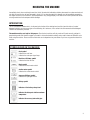
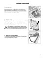
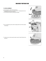
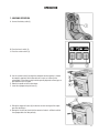
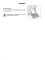
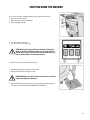
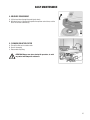
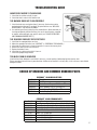
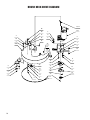
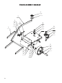
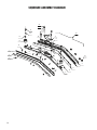
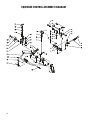
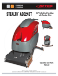
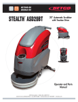
E83025-00 E29937-00
E29936-00
CREWMAN AS20B
™
20” Automatic Scrubber
with Brush Assist
Operator Manual
1001 Brown Avenue • Toledo, Ohio 43607-0127
Customer Service: 888-GO-BETCO • Fax: 800-445-5056 • Technical Service: 877-856-5954 • www.betco.com
1
TABLE OF CONTENTS
RECEIVING THE MACHINE............................................. 3
TECHNICAL SPECIFICATIONS......................................... 4
GENERAL SAFETY REGULATIONS.................................. 5
MACHINE PREPARATION.........................................6 - 10
OPERATION...........................................................11 - 12
TURNING OFF THE MACHINE....................................... 13
DAILY MAINTENANCE............................................14 - 15
WEEKLY MAINTENANCE............................................... 16
TROUBLESHOOTING.................................................... 17
BRUSH AND SELECTION USE...................................... 17
PARTS DIAGRAMS AND LISTINGS........................18 - 39
ELECTRICAL SYSTEM...........................................40 - 41
WARRANTY.................................................................. 44
2
RECEIVING THE MACHINE
Immediately check, when receiving the machine, that all the materials indicated on delivery documents have been received and
also that the machine has not been damaged in transit. If it has been damaged, this damage must be immediately reported to
the shipper and also to our customer’s service department. Only acting promptly in this manner will make it possible to receive
missing material and to be compensated for damage.
INTRODUCTION
This is an automatic scrubber which, via the mechanical action of the rotating brush and the chemical action of a water/
detergent solution, can clean many types of hard flooring. As it advances, it also collects the dirt removed and the detergent
solution not absorbed by the floor.
The machine must be used only for this purpose. Even the best machines will only work well if used correctly and kept in
good working order. We therefore suggest you read this instruction booklet carefully and re-read it whenever difficulties arise
while using the machine. Please contact our technical service department or your dealers if you have any questions about the
machine.
SYMBOLS USED ON THE MACHINE
Cock symbol
Indicates the cock lever
Indicates the cock open signal lamp
Brush base lift/lower symbol
Indicates the base lift lever
Brush symbol
Indicates the brush motor switch
Suction motor symbol
Indicates the suction motor switch
Squeegee lift/lower symbol
Indicates the squeegee lift lever
Battery symbol
Indicator of the battery charge level
Indicates the detergent solution maximum
temperature
Indicates the recovery tank outlet pipe
3
TECHNICAL DESCRIPTION Measurement Unit
Crewman™ AS20B
Working width
In (mm)
20 (508)
Rear squeegee width
In (mm)
26 (660)
ft2/h (m2/h)
18,500 (1720)
in (mm)
20 (500)
RPM
275
lb. (Kg)
50 (22)
V / HP (V / W)
24 / 0.54 (24 / 400)
Work capacity
Brush & Pad (diameter)
Brush RPM
Brush pressure
Brush motor
Drive Type
Vacuum motor
Semi-Automatic
V / HP (V / W)
24 / 0.5 (24 / 370)
Vacuum motor suction
inches of water (mbar)
40 (100)
Solution tank capacity
Gal (l)
9 (33)
Recovery tank capacity
Gal (l)
10.5 (40)
Weight of machine (excluding batteries)
lb. (Kg)
165 (75)
V / A
24 / 12
in x in x in
14.2 x 12.8 x 10.0
(mm/mm/mm)
(360 /325 /250)
dBA
65
Charger
Battery compartment dimensions (Length / Height / Width)
Noise level
4
GENERAL SAFETY REGULATIONS
The regulations below must be carefully followed in order to avoid harm to the operator and damage to the machine.
• Read all labels on the machine carefully. Do not cover them for any reason and replace them immediately if they become
damaged.
• The machine must be used exclusively by authorized and trained personnel.
• When operating the machine be careful of other people.
• The machine is not designed for cleaning carpets.
• The power cable outlet must be provided with a proper ground.
• Avoid damaging the power cable of the battery charger by crushing, bending, cutting or stressing it.
• Whenever the power cable of the battery charger is damaged, immediately contact a BETCO service center.
• Do not mix different types of detergent as this may produce harmful gases.
• Do not set containers on the machine.
• Machine storage temperature is between -10°F and 130°F, never store outside under humid conditions.
• Operating conditions: room temperature between 33°F and 100°F with relative humidity between 30% to 95%.
• Only use the machine in closed areas and do not expose it directly to rain.
• Never use the machine in an explosive environment.
• Do not use the machine as a means of transport.
• Never use acidic chemicals which could damage the machine.
• Avoid running the brushes with the machine stopped; this could damage the floor.
• Never vacuum up flammable liquids.
• Never use the machine to gather dangerous powders.
• Use a powder fire extinguisher in case of fire. Do not use water.
• Do not hit against shelving or scaffolding. The operator must always be equipped with the appropriate safety device
(gloves, shoes, helmet, glasses, etc.)
• Do not use the machine on surfaces with an inclination greater than the one shown on the serial plate.
• The machine is designed to wash and dry floors simultaneously. Signal the presence of wet floors with suitable signs.
• If the machine does not work properly, perform routine maintenance. Otherwise, request the assistance of the BETCO technical service.
• When replacing parts ask for ORIGINAL spare parts from your Authorized BETCO Dealer and/or Retailer.
• Always turn off the machine and disconnect the battery connector whenever maintenance is performed.
• Never remove guards that require tools for removal.
• Never wash the machine with direct or pressurized jets of water or with corrosive substances.
• Have your BETCO service center check the machine once a year.
• To prevent the formation of scale in the solution tank filter, do not store the machine with detergent solution in the tanks.
• Before using the machine make sure that all doors and covers are positioned as shown in this operating and maintenance
manual.
• When your BETCO machine is ready to be retired, the machine must be disposed of properly. It contain oils and electronic
components. The machine was built using totally recyclable materials.
• Use only brushes furnished with the machine or those specified in the user's manual. Use of other brushes can compromise safety.
• When removing the battery, unplug the battery connection, unplug the charger and disconnect the battery terminals.
• Before recycling the machine, remove the battery.
5
MACHINE PREPARATION
1. HANDLING THE PACKED MACHINE
Do not place more than two packages on top of each other.
The total weight is 220 lb. (100 kg).
The overall dimensions of the package are:
A : 50 in (1260 mm)
B : 26 in (660 mm)
C : 48.4 in (1230 mm)
2. HOW TO UNPACK THE MACHINE
A. Remove outer packaging.
B. The machine is strapped to it's pallet.
C. Remove the strap.
D.Use a ramp to get the machine down from the pallet, pulling it backwards.
E. Keep the pallet for any future transport needs.
6
MACHINE PREPARATION
3. BATTERY INSTALLATION
The machine will be supplied with a battery charger and either two 12V Wet or AGM batteries. The batteries must be housed
in the battery tray in the battery compartment beneath the recovery tank.
To insert the batteries you must:
A. Open the recovery tank lid.
B. Disconnect the squeegee hose (1) from the recovery tank.
C. Remove the suction cap (2) by turning it counterclockwise.
D. Disconnect the "recovery tank" drain hose from the proper hook.
E. Remove the recovery tank.
F. Place the battery.
G. Connect the battery connector (2) to the machine connector (1).
H. Reassemble everything.
WARNING: To avoid acid spillage you can use sealed batteries.
WARNING: Perform one battery charging cycle before using the machine.
4. BATTERY CHARGER
Make sure that the battery charger is suitable to the installed battery, both in capacity and in type (lead/acid or GEL and
equivalent).
WARNING! Never charge a GEL battery with an unsuitable battery charger. Strictly follow the instructions
provided by the battery and battery charger manufacturer.
In order to avoid permanent damages to the battery, they should never be totally discharged. To do this, they
should be recharged within a few minutes after the battery discharge signal starts to flash.
NOTE: Never leave the battery completely discharged, even if the
machine is not being used.
ATTENTION! For daily recharging of the battery it is necessary to strictly follow the instructions provided by
the manufacturer or dealer. Specialists must carry out all installing and maintenance procedures. Danger of
exhalation of gas and emission of corroding substances. Danger of fire: Keep away from flames.
7
MACHINE PREPARATION
5. BATTERY CHARGE LEVEL GAUGE
The batteries’ indicator is digital with 4 fixed positions and a blinking one. The
numbers, which appear on the display, show the approximate charge level.
4 = maximum charge, 3 = charge 3/4, 2 = charge 2/4, 1 = charge 1/4,
0 = (blinking) discharged batteries)
WARNING! Some seconds after that “0” blinks, the brush motor
automatically switches off. Anyway, the machine can finish to dry
before recharging the batteries.
6. INSTALLING THE SQUEEGEE
The squeegee is supplied separately from the machine, due to packing reasons.
It must be installed as shown in the picture, threading the retaining pin into the
squeegee column. Put the squeegee suction hose into its sleeve.
7. SQUEEGEE HEIGHT ADJUSTING
The squeegee height is maintained by the guide wheels. To adjust this: rotate
the wing nuts (1) counterclockwise to lift the squeegee and clockwise to lower
it.
Note: The right and left wheels must be set at the same height, to allow the
squeegee to work parallel to the ground.
8. SQUEEGEE INCLINATION ADJUSTING
During operation, the back rubber is to be lightly inclined backwards (about 5
mm, on its whole length). Should it be necessary, you can increase the rubber central inclination by inclining backwards the squeegee body, turning the
regulator counterclockwise (1). To increase the bending of the rubber on the
squeegee sides, turn the register clockwise. Once the adjustment is finished,
lock the block nut.
8
MACHINE PREPARATION
9. RECOVERY TANK
Open the cover and check if the suction plug (2) is insert correctly and its
notches are locked turning the plug clockwise and is well connected with the
hose which leads to the suction motor.
Furthermore check, that the squeegee hose (1) is well connected and that the
exhaust plug at the back of the machine is closed.
10. SOLUTION WATER
Fill the solution tank with clean water at a temperature not in excess of 120°F
(50°C). Add liquid detergent in the amounts and using the procedures recommended by the detergent manufacturer. Use only a minimal percentage of
detergent to prevent formation of an excessive quantity of foam, as this could
damage the suction motor. Close the cap.
ATTENTION! Always use low-foam detergent. Introduce a small
amount of anti-foam detergent in the recovery tank before operating, to be sure to prevent foam formation. Never use pure acids.
11. INSTALLING THE SPLASH-GUARD
The splashguard is supplied separately from the machine, for packing reasons,
and is to be installed as shown in the picture.
9
MACHINE PREPARATION
12. BRUSH ASSEMBLY
A. Push the pedal in order to lift the brush base.
B. With lifted brush base try to bring the brushes in the right position corresponding to the center of the machine.
C. Let the brush base down by releasing on the pedal.
D.Press the operator present control lever (6) and the brush will be hooked
automatically.
E. In order to vary the advancement speed act upon the knob indicated in the
illustration.
10
OPERATION
1. MACHINE OPERATION
A. Connect the battery cable (1).
B. Press the brush switch (2).
C. Press the suction switch (3).
D.Use the solution knob (4) to adjust the detergent solution quantity: it should
be enough to regularly wet the floor but not as much as to flow out the
splashguard. Please note the right solution quantity depends on floor type, on
dirt importance and on speed.
E. Release the pedal and let the base lower.
F. Lower the squeegee using the lever (5).
G.Pulling the trigger will cause (6) the brushes to start turning and the squeegee starts drawing in.
H.During the first few feet check that the amount of water is sufficient and that
the squeegee dries the floor perfectly.
11
OPERATION
2. OVERFLOW DEVICE
The machine is supplied with float that trips whenever the recovery tank is full,
closing the suction tube. In this case you should empty the recovery tank by
removing the outlet pipe cap.
ATTENTION! Always wear gloves during this procedure, to avoid
any contact with dangerous substances.
12
SHUTTING DOWN THE MACHINE
At the end of the work, and before performing any type of maintenance:
1. Close the solution valve(1).
2. Raise deck by pressing on foot pedal.
3. Raise squeegee lever (2).
4. Turn off the brush switch (3).
5. Turn off suction motor switch (4).
ATTENTION! If after having switched off the brush switch (3) the
display of the battery indicator remains on, this means that, the
solution valve is open. Close the water valve using the lever (1) in
order to avoid leakage of the detergent solution.
6. Move the machine to the water disposal point.
7. Hold the hose placed on the back of the machine.
8. Remove the outlet cap and empty the tank.
ATTENTION! Always wear gloves during this procedure to avoid any
contact with dangerous substances.
9. Disassemble the brush and clean it by a jet of water (for the disassembly of
the brush see the following “DISASSEMBLY OF THE BRUSH”).
13
DAILY MAINTENANCE
1. RECOVERY TANK CLEANING
A. Hold the recovery tank outlet hose.
B. Remove the outlet cap and empty the tank.
ATTENTION! Always wear gloves during this procedure, to avoid
any contact with dangerous substances.
C. Lift the recovery tank lid.
D.Remove the suction cap (1) turning it counterclockwise.
E. Remove the filter and its protection.
F. Rinse the tank with a jet of water.
2. SUCTION FILTER CLEANING
A. Lift the lid.
B. Remove the suction cap turning in counterclockwise.
C. Remove the filter.
D.Clean the filter walls and bottom by a jet of water.
E. Carry out the cleaning procedures very carefully.
F. Reassemble everything.
3. CLEANING THE VACUUM HOSE FILTER
The squeegee must be in perfect working condition to achieve a good drying
process.
Proceed as follows to clean it:
A. Remove the hose from the squeegee.
B. Loosen the knobs (1) shown in picture.
C. Remove the mouth and clean it.
D.Carefully clean the inside of the squeegee.
E. Carefully clean the squeegee blades.
F. Reassemble everything.
14
DAILY MAINTENANCE
4. BRUSHES DISASSEMBLY
A. Lift the brush base through the pedal (push down).
B. With brush base in lifted position operate the operator control lever, and the
brush will unhook automatically.
5. CLEANING SOLUTION FILTER
A. Take off the filter on the solution tank.
B. Clean it thoroughly.
C. Reassemble everything.
ATTENTION! Always wear gloves during this procedure, to avoid
any contact with dangerous substances.
15
WEEKLY MAINTENANCE
1. CLEANING SQUEEGEE HOSE
Weekly, or whenever the suction in insufficient, it is necessary to check that the
squeegee hose is not obstructed. Should it be the case, proceed as follows to
clean it:
A. Unthread the hose from the squeegee sleeve.
B. Unthread the other end from the recovery tank.
C. Wash the inside of hose by a jet of water.
D.To reassemble the hose repeat the above-mentioned operations.
ATTENTION! Do not wash the hose connecting the vacuum motor to
the suction cap.
2. CLEANING SOLUTION TANK
A. Remove the cap from the solution tank.
B. Rinse with a jet of water.
C. Remove the outlet cap (1) and empty the tank.
ATTENTION! Always wear gloves during this procedure, to avoid
any contact with dangerous substances.
3. REAR SQUEEGEE BLADE REPLACEMENT
Check the squeegee blade wear and replace them if necessary.
Proceed as follows:
A. Unthread the squeegee hose from sleeve.
B. Remove the pin from column.
C. Remove the squeegee from its support.
D.Loosen the wing nuts (1) holding the squeegee blades and take them off.
E. Replace the squeegee blades.
To reassemble the squeegee repeat the above-mentioned operations.
16
TROUBLESHOOTING GUIDE
INSUFFICIENT WATER TO THE BRUSHES
1. Check that the solution valve (1) is open.
2. Check that there is water in the solution tank.
THE MACHINE DOES NOT CLEAN PROPERLY
1. Check the brush wear and replace them if necessary (the brushes must be
replaced when bristles are 15 mm high). To replace brushes see “BRUSHES
DISASSEMBLY” and ”BRUSH ASSEMBLY”.
2. Use another type of brush rather than the standard brush. We recommend, for
cleaning exceptionally difficult dirt floors, the use of special brushes, supplied
on request and according to your specific needs (see “CHOICE OF BRUSHES
AND COMMON ORDERED PARTS”).
THE SQUEEGEE DOES NOT DRY EFFECTIVELY
1. Check that the squeegee blades are clean.
2. Adjust the squeegee inclination (see “SQUEEGEE” in “PREPARING THE MACHINE”).
3. Check that the suction hose is correctly housed in its seat on the recovery tank.
4. Remove the whole suction unit and clean it.
5. Replace the blades if worn.
6. Check that the suction motor switch is turn on.
7. Check the squeegee height wheels.
TOO MUCH FOAM IS GENERATED
Check that low-foam detergent is used. Add, if necessary, a small quantity of defoaming liquid to recovery tank.
Please remember that more foam is generated when the floor to be cleaned it is not very dirty. In this case use a more diluted
detergent solution.
CHOICE OF BRUSHES AND COMMON ORDERED PARTS
CREWMAN™ AS20B BRUSH OPTIONS
Item Number Description
E88268-00
Pad Driver
E88330-00
Brush, General Purpose 20" 0.3mm PPL
E88269-00
Brush, Medium Duty 20" 0.55mm PPL
E88270-00
Brush, Heavy Duty 20" 0.7mm PPL
E88271-00
Brush, Stripping Grit 20" 1.2mm
Item Number
E83909-00
E12686-00
E88276-00
E12560-00
E11767-00
E86276-00
E88030-00
E88035-00
CREWMAN™ AS20B COMMON PARTS
Description
Front Squeegee Blade, Polyurethane 30" x 1 3/4" x 1/8"
Wiping Squeegee Blade, Gum Rubber 30 3/4" x 1 3/4" x 1/8"
Wiping Squeegee Blade, Polyurethane 30 3/4" x 1 3/4" x 1/8"
Support Blade, Polyurethane 30 3/4" x 1 3/4" x 1/8"
Battery 12V 130AH Wet
Battery 12V 115AH Wet
Battery 12V 110AH AGM
Charger 24VDC 12AMP
17
BRUSH DECK DIAGRAM
18
BRUSH DECK PARTS LISTING
Item# Part # Description
Qty.
Item# Part # Description
Qty.
1
E88272 Brush Deck Splash Guard 1
4
E83802 Hex Bolt M8x30 Zinc
3
2
E20073 Brush Deck
1
5
E81709 Nyloc Hex Nut, M8 Zinc
3
3
E83970 Bushing
3
6
E83404 Flat Washer M9x24x2.5 Zinc
8
19
BRUSH DECK DRIVE DIAGRAM
19.11
20
9
10
24
3
12
4
25
2
19.1
5
5
25
9
1
25
28
5
32
15
25
14
13
34
26
33
7
23
18
8
9
16
6
5
11
5
20
9
27
31
4
3
21
17
29
BRUSH DECK DRIVE PARTS LISTING
Item# Part # Description
Qty.
Item# Part # Description
Qty.
1
E20011 Motor Mount Plate
1
18
E82845 Spacer
3
2
E82312 Bushing
2
19
E88245 Motor, Geared 24V 400W 140 RPM
1
3
E83833 Hex Bolt M8x25 Zinc
2
19.11
E20451 Fitting, Solution Delivery Tube
1
4
E83404 Flat Washer M9x24x2.5 Zinc
2
20
E83565 Knob
1
5
E81709 Nyloc Hex Nut, M8 Zinc
6
21
E88246 Brush, Flange Threaded
1
6
E83895 Wheel 80 OD x 23 W
2
23
E83491 Spring
1
7
E83524 Bushing
2
24
E83881 Hex Bolt M5x20 Zinc
1
8
E81918 Flat Washer M9x32x2.5 Zinc
2
25
E88010 Hex Nut, M5
4
9
E81874 Flat Washer M8x17x1.6 Zinc
4
26
E83489 Rings
1
10
E83830 Hex Bolt M8x40 Zinc
2
27
E20290 Flat Hd Soc Machine Screw M5x16 SS
2
11
E82309 Spring, Compression
2
28
E20507 Brush Deck
1
12
E83331 Knob
1
29
E20584 Retainer
1
13
E83547 M6x16 Bolt, Zinc Hex Head 4
31
E86169 Band Clamp
1
14
E82774 Lock Washer, M6 Zinc
4
32
E83823 Screw M5x20/ SS Custom
1
15
E20093 Carriage Bolt M8x25 Zinc
1
33
E20592 Dowel Pin M8
1
16
E20297 Flat Hd Soc Machine Screw M8x16 Zinc
3
34
E83672 Hex Jam Nut, M8x5 SS
1
17
E82844 Clutch Plate
1
21
FRAME ASSEMBLY DIAGRAM
8
7
2
4
22
14
18
17
23
19
5
3
24
1
12
15
11
25
16
6
21
13
9
20
10
22
FRAME ASSEMBLY PARTS LISTING
Item# Part # Description
Qty.
Item# Part # Description
Qty.
1
E20430 Main Frame ASM
1
14
E81635 Screw, M6X45
6
2
E82525 Arm s42 1
15
E81735 Hex Bolt M12x35 Zinc 2
3
E82833 Arm 1
16
E20705 Nyloc Hex Nut, M5 Zinc
2
4
E82834 Pivot Block 6
17
E83550 NyLoc Hex Nut, M6 Zinc
6
5
E22146 Coupling
1
18
E83381 Nyloc Hex Nut, M10 Zinc
1
6
E20647 Axle Shaft
2
19
E83829 Hex Jam Nut, M12X7 Zinc
2
7
E20370 Foot Pedal
1
20
E81627 Nyloc Hex Nut, M16 Zinc
2
8
E83669 Pedal cover 1
21
E20122 Flat Washer M5 x 15 x 1.5 SS 2
9
E20501 SPLASH GUARD 1
22
E82761 Washer 6x12x1.6 6
10
E88103 Spacer 2
23
E81020 Washer, 11x30X2.5
1
11
E82551 Transport Wheel 175 OD x 45 W 2
24
E81738 Flat Washer M4x12x3 Zinc 2
12
E82529 Caster, Rear Abila 2
25
E81948 Flat Washer M20x26x1.5 AL 2
13
E20488 Carriage Bolt M5x16 Zinc
2
23
SQUEEGEE ASSEMBLY DIAGRAM
23
17
6
16
30
22
20
14
9
10
12
18
1
3
15
19
8
7
24
21
2
11
19
5
24
4
SQUEEGEE ASSEMBLY PARTS LISTING
Item# Part # Description
Qty.
Item# Part # Description
Qty.
1
E83909 Squeegee Blade, Polyurethane 30" x 1 3/4" x 1/8" 1
14
E82253 Bushing, Brass OD 11.95mm x ID 8.9mm x L 8.45mm 1
2
E12560 Squeegee Blade, Polyurethane 30 3/4" x 1 3/4" x 1/8" 1
15
E83851 Screw, Pan Hd Phil Self Tap M5.5x13 SS
2
3
E82608 Band Clamp 29 1/2" x 7/8" x 1/8"
1
16
E83802 Hex Bolt M8x30 Zinc
2
4
E82676 Band Clamp 31 1/4" x 7/8" x 1/8"
1
17
E82707 Set Screw Hex Soc Flat End M6x40 SS
8
5
E88240 Squeegee Body
1
18
E81848 Flat Hd Soc Machine Screw M6x25 SS
12
6
E83911 Stud Bolt M10x46 Custom
1
19
E20114 Hex Jam Nut, M6X3 SS
2
7
E83590 Chain
1
20
E83875 Hex Jam Nut, M10X6 Zinc
4
8
E83945 Stud Bolt M10x33 Custom
1
21
E20117 Nyloc Hex Jam Nut, M6x9 SS
2
9
E82307 Squeegee Vacuum Adapter
1
22
E81874 Flat Washer M8x17x1.6 Zinc
2
10
E83971 Gasket
1
23
E83810 Knob
8
11
E12686 Squeegee Blade, Gum Rubber 30 3/4" x 1 3/4" x 1/8" 1
24
E83591 Knob
1
12
E82451 Wheel 45 OD x 25 W
2
30
E88536 Squeegee Assembly
1
13
E83914 Hex Bolt M6x20 SS
2
25
TANK ASSEMBLIES DIAGRAM
3.5
1.1.8
3.4
3.3
3.6
2.5
3.2
1.2.3
1.2.7
8
1.1.4
7
1.1.1
3.1
2.2
1.1.2
1.1.7
6
1.1.11
1.1.13
3.7
1.1.12
1.3.7
1.2.2
1.1.16
1.3.5
2.6
1.3.3
1.3.4
1.3.6
1.2.6
1.2.5
2.4
1.2.4
2.3
2.1
2.8
2.7
1.2.11
1.2.1
13
1.1.9
1.1.10
1.2.10
1.2.8
1.2.9
26
1.3.2
1.1.14
11
1.1.15
10
1.1.17
12
1.1.6
1.1.3
1.1.5
4
5
1.3.1
TANK ASSEMBLIES PARTS LISTING
Item# Part # Description
Qty.
Item# Part # Description
Qty.
1.1.1 E82319 Solution Tank, Crewman AS20B
1
1.3.4 E87296 Drain Hose Clip 1
1.1.2 E82332 Gasket 1
1.3.5 E83037 Flat Washer M4x12x1.6 Zinc 2
1.1.3 E83560 Filter Asm 1
1.3.6 E85784 Vac Motor Deadening 1
1.1.4 E82612 Filter 1
1.3.7 E20106 Screw
2
1.1.5 E83561 Bracket WS17 1
2
E83123 Float Protection Assembly
1
1.1.6 E83533 Angle WS17 1
2.1
E81006 Vacuum Splash Guard 1
1.1.7 E22147 Support
1
2.2
E81615 Filter 1
1.1.8 E82429 Cap 1
2.3
E83338 Float WS17 1
1.1.9 E83851 Screw, Pan Hd Phil Self Tap M5.5x13 SS
4
2.4
E83605 Split pin 2
1.1.10 E83799 Flat Washer M6.6x18x2 SS 2
2.5
E82611 Rod 1
1.1.11 E81614 Stud bolt 2
2.6
E82313 Grommet 1
1.1.12 E86701 Nut M6 2
2.7
E82490 Hose, Abila
1
1.1.13 E83550 NyLoc Hex Nut, M6 Zinc
2
2.8
E83799 Flat Washer M6.6x18x2 SS 1
1.1.14 E83547 M6x16 Bolt, Zinc Hex Head
2
3 E85756 Recovery Tank Lid Assembly 1
1.1.15 E82774 Lock Washer, M6 Zinc
2
3.1
E82450 Cover 1
1.1.16 E83707 Deadening WS17 1
3.2
E83994 Gasket 1
1.1.17 E82798 Washer, 6x18x1.5
2
3.3
E82267 Coupling 1
1.2.1 E81470 Abila Recovery Tank 1
3.4
E83850 Flat Washer M5x20 SS 2
1.2.2 E83995 Ring 1
3.5
E83934 Screw m5x25 2
1.2.3 E83796 Screw, Pan Hd Phil Self Tap M4.2x16 Zinc
4
3.6
E20705 Nyloc Hex Nut, M5 Zinc
2
1.2.4 E82254 Chain Protector 2
3.7
E82381 Gasket Ring 1
1.2.5 E88430 Support Chain Tank Cover 2
4
E83934 Screw m5x25 4
1.2.6 E83881 Hex Bolt M5x20 Zinc 4
5
E83850 Flat Washer M5x20 SS 4
1.2.7 E82352 Cover, Abila
1
6
E22149 Foam Pad
2
1.2.8 E83966 Hose Clamp 1
7
E81619 Cable Tie Holder 4
1.2.9 E88023 Hose, Drain Assembly Abila 42
1
8
E83796 Screw, Pan Hd Phil Self Tap M4.2x16 4
1.2.10 E85764 Gasket 1
9
E20089 Hex Bolt M6x22 Zinc
2
1.2.11 E85763 Connector 1
10
E82774 Lock Washer, M6 Zinc
4
1.3.1 E22148 Cover, Back Panel
1
11
E82798 Washer, 6x18x1.5
4
1.3.2 E83164 Micro Switch 1
12
E20088 Hex Bolt M6x18 Zinc
2
.3.3 E22293 Screw
2
13
E83536 Squeegee hose 1
27
SQUEEGEE CONTROL ASSEMBLY DIAGRAM
28
SQUEEGEE CONTROL ASSEMBLY PARTS LISTING
Item# Part # Description
Qty.
Item# Part # Description
Qty.
1
E82428 Wheel 52 OD x 28 W
2
40
E85499 Hex Nut, M8x6.5 SS
1
2
E82273 Bushing
2
41
E81874 Flat Washer M8x17x1.6 Zinc
2
3
E85497 Weldment, Squeegee Wheel Support
2
42
E83550 NyLoc Hex Nut, M6 Zinc
2
4
E82329 Threaded Pin
2
43
E88585 Washer, Flat, M6 x 18, Zinc
4
5
E83531 Knob
2
44
E83381 Nyloc Hex Nut, M10 Zinc
1
6
E81634 Spring Compression
2
45
E81736 Flat Washer M17x30x3 Zinc
1
7
E85498 Retaining Ring, E-Style, M9
2
46
E10646 Bolt, M10 x 45
1
8
E22146 Coupling
1
47
E83535 Hex Nut, M5x5 Zinc
1
9
E86246 Coupling, Squeegee
1
48
E83881 Hex Bolt M5x20 Zinc
1
10
E83541 Extension Tube
1
49
E83656 Hex Nut, M8x6.5 Zinc
2
11
E83655 Adjuster Knob
1
50
E85721 Screw, Machine M6 x50
2
12
E83453 Squeegee Lift Cable
1
51
E85722 Flat Washer M13x24x2.5 Zinc
2
13
E83542 Clip WS17
1
53
E82456 Hex Bolt M6x14 Zinc
1
14
E83538 Fork WS17
1
55
E83547 M6x16 Bolt, Zinc Hex Head
1
15
E81477 Knob 25X50 M8
1
56
E82772 Hex Bolt M6x20 Zinc
1
16
E82550 Handle - Lever
1
57
E82256 Nyloc Hex Nut, M5x7 Zinc
1
17
E82698 Bushing
2
58
E88594 Washer, Split Lock, M6, Zinc
3
18
E83540 Lever
1
29
VACUUM MOTOR ASSEMBLY DIAGRAM
5
4
3
1.6
1.3
1.2
1.1
1.5
1.4
1.7
2
30
VACUUM MOTOR ASSEMBLY PARTS LISTING
Item# Part # Description
Qty.
Item# Part # Description
Qty.
1
E83454 Vacuum Motor, 24 volt
1
1.6
E87975 Stud Bolt Tripla 2
1.1
E83897 Connector, Electrical Housing 30A
2
1.7
E83454 Vacuum Motor, 24 volt
1
1.2
E83883 Lug, Electrical 30A
2
2
E83966 Hose Clamp 1
1.3
E83935 Wire Tie 1
3
E82761 Washer 6x12x1.6 2
1.4
E82838 Motor Plaque 1
4
E83550 NyLoc Hex Nut, M6 Zinc
2
1.5
E88017 Screw, Pan Hd Phil Self Tap M4.8x13 SS
4
5
E82371 Vac exhaust hose 1
31
SOLUTION ASSEMBLY DIAGRAM
12
13
11
10
9
8
6
4
5
7
14
1
2
3
14
32
15
SOLUTION ASSEMBLY PARTS LISTING
Item# Part # Description
Qty.
Item# Part # Description
Qty.
1
E83943 Nipple, Double Male 3/8"
1
9
E82309 Spring, Compression
1
2
E83361 Ball Valve, 5/8 Double Female
1
10
E83798 Flat Washer M6x30x3 PVC Black 2
3
E82269 Barbed Fitting, 3/8 in.
1
11
E83850 Flat Washer M5x20 SS 1
4
E83534 Solution valve lever 1
12
E83639 Solution control knob 1
5
E83816 Screw 1
13
E83535 Hex Nut, M5x5 Zinc
1
6
E83532 Solution rod 1
14
E83499 Hose Clamp
2
7
E83537 Clip 1
15
E82306 Hose 1
8
E83845 Nut, M5
1
33
ELECTRIC COMPONENTS DIAGRAM
1
6
7
3
4
7
5
2
34
ELECTRIC COMPONENTS PARTS LISTING
Item# Part # Description
Qty.
Item# Part # Description
Qty.
1
E22151 Electric System
1
5
E82761 Washer 6x12x1.6 4
2
E22152 Handlebar Assembly
1
6
E82798 Washer, 6x18x1.5
4
3
E83547 M6x16 Bolt, Zinc Hex Head
4
7
E82774 Lock Washer, M6 Zinc
8
4
E81983 Hex Bolt M6x40 Zinc 4
35
HANDLEBAR ASSEMBLY DIAGRAM
16
18
16
4
30
13
32
15
31
7
29
3
36
28
34
33
13
22
14
2
1
10
13
9
10
36
12
8
HANDLEBAR ASSEMBLY PARTS LISTING
Item# Part # Description
Qty.
Item# Part # Description
Qty.
1
E83407 Handle bar body WS17 1
16
E83328 Vacuum switch 2
2
E83408 Handle bar (pipe) WS17 1
18
E83175 battery level display 1
3
E83465 WS17 lever 2
22
E83615 Handle grip WS17 2
4
E83405 Handle bar cover WS17 1
28
E82796 Switch, Momentary
1
7
E82308 Pin 2
29
E22153 Mounting Plate
1
8
E20489 Soc Hd Cap Screw M6x20 Zinc
2
30
E88244 Fuse Holder for Crewman AS20B 1
9
E20342 Soc Hd Cap Screw M6x40 Zinc 2
31
E83168 Fuse, 3 amp
1
10
E20107 Screw, Pan Hd Phil Self Tap M4.2x16 SS
4
32
E86144 Screw, Battery Cover 1
12
E88042 Flat Hd Soc Machine Screw M6x16 Zinc 1
33
E82704 Gasket 1
13
E83550 NyLoc Hex Nut, M6 Zinc
5
34
E83157 battery indicator card 1
14
E82761 Washer 6x12x1.6 1
36
E22154 Spacer 15x15x92 1
15
E82798 Washer, 6x18x1.5
2
37
ELECTRIC CONTROLS DIAGRAM
10
10
11
20
21
18
23
21
23
1
19
13
12
22
17
16
8
15
9
4
5
6
3
7
38
2
4
9
8
14
ELECTRIC CONTROLS PARTS LISTING
Item# Part # Description
Qty.
Item# Part # Description
Qty.
1
E22155 Electric Panel
1
13
E83628 Contactor 24VDC 1
2
E83540 Lever WS17 1
14
E81954 Washer, Lock
2
3
E82550 Handle - Lever S42 1
15
E83816 Screw 2
4
E82698 bushing 2
16
E82305 Fuse 50A faston brushes motor 1
5
E82772 Hex Bolt M6x20 Zinc 1
17
E83972 Fuse 30A fasten 1
6
E83550 NyLoc Hex Nut, M6 Zinc
1
18
E81642 Fuseholder 2
7
E81477 Knob 25X50 M8 1
19
E88497 Fuse Block End Cap 1
8
E82456 Hex Bolt M6x14 Zinc 2
20
E83664 Insulator WS17 1
9
E82774 Lock Washer, M6 Zinc
2
21
E20123 Lock Washer M5x1.6 Zinc 2
10
E83160 Relay 24VDC 30A 1
22
E20122 Flat Washer M5 x 15 x 1.5 SS 2
11
E83867 Nyloc Hex Nut, M4x6 Zinc
1
23
E81437 Screw 2
12
E83887 Screw M4X10 1
39
ELECTRICAL DIAGRAM
40
ELECTRICAL LISTING
Item# Part # Description
Item# Part # Description
1
E83328
Vacuum Switch
10
E86208
Connector, SB50, Red, #6, w/ Lugs
2
E83175
Battery Level Display
11
E86208
Connector, SB50, Red, #6, w/ Lugs
3
E83328
Vacuum Switch
13
Various Battery
4
E83157
Battery Indicator Card
M1
E88245
Motor, Geared 24V 400W
5
E82796
Switch, Momentary
M2
E83454
Vacuum Motor, 24 volt
6
E83664 Insulator
F1
E83168
Fuse, 3 amp
7
E83160
Relay 24VDC 30A
F2
E82305
Fuse 50A Brush Motor
8
E83628
Contactor 24VDC
F3
E83926
Fuse 30A Vacuum Motor
9
E83164
Micro Switch
41
42
43
BETCO US WARRANTY POLICY
10 year coverage
3 Year Coverage
1 Year Coverage
Subject to the conditions stated below,
Betco warrants parts and labor on
rotationally molded polyethylene tanks/
housings and injection molded vacuum
head assemblies to be free from defects
in materials and workmanship for
a period of ten years to the original
purchaser.
Subject to the conditions stated below,
Betco warrants parts and labor on all
other Betco components to be free from
defects in materials and workmanship
for a period of three years to the original purchaser.
Subject to the conditions stated below,
Betco offers a limited warranty on parts
and labor on the following equipment:
parts and accessories to be free from
defects in materials and workmanship
for a period of one year to the original
purchaser.
• PowerUp™ 14 Upright Vacuum: #E29990-00
• Bac Pac Lite Vacuum: #85903-00
• FiberPRO® Floor Dryer: #85507-00
• WORKMAN™ Series Vacuums:
#85024-00, #85025-00, #83012-00,
#85027-00
• All Tools and Accessories
• All Battery Chargers
• All Batteries are pro-rated for 1 year
Allowable Travel Time Warranty Reimbursement:
Eligible equipment: All battery and propane powered equipment products. Warranty period: 90 days from date of sale to the
original purchaser. A maximum 180 mile round trip at 50 cents per mile will be allowed for warranty consideration.
Propane Machine Warranty:
Kawasaki engines are warranted by Kawasaki for a period of 2 years against manufacturer defects. All other components
(except wear items)* are warranted by Betco for a period of 3 years.
*Wear Items exempt from Warranty consideration include but may not be limited to: power cords, transport wheels,
vacuum bags, belts, squeegee blades, pad drivers, clutch plates, handle grips, filters, screens, throttle cables, brushes
and carbon brushes.
Subject to the conditions and exceptions stated in this warranty, Betco warrants the Betco products to be free from defects in
material and workmanship, under normal use and service, for the periods listed under the warranty policy to the original purchaser. At any time during the warranty period, Betco will furnish replacement parts for the Betco parts to the original purchaser. Such parts will be furnished and charged including transportation costs, to the original owner through any Betco authorized
Service Distributor. If the original part is returned within the warranty policy period from date of delivery for inspection by
Betco and is found to be defective the owner will be credited for the cost of replacement parts plus shipping and handling.
Replacement parts that have become defective through wear or abuse are not included in this warranty.
This warranty does not apply to damage or defect caused by accident, misuse. Negligence, fire, or to any Betco product which
has been serviced or repaired by other than an authorized Betco Service Distributor or Betco factory personnel. This warranty
is void if products are used for any purpose other than that which was intended. There are no other warranties expressed or
implied. In no event shall Betco be liable for incidental or consequential damages or any damage to person or property. (Please
note some states do not allow the exclusion or limitations for incidental and consequential damages).
44
1001 Brown Avenue • Toledo, Ohio 43607-0127
Customer Service: 888-GO-BETCO • Fax: 800-445-5056 • Technical Service: 877-856-5954 • www.betco.com
92158-92 Sept15D