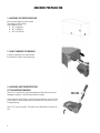
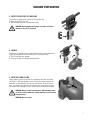
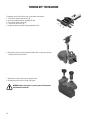
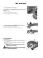
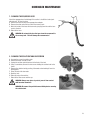
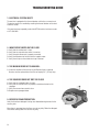
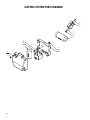
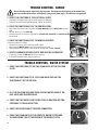
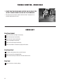
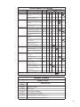
1
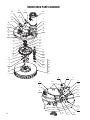
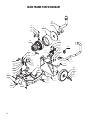
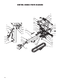
E88778-00
GENIE CE HD APS
™
14” Cord Electric
Heavy Duty All Purpose
Automatic Scrubber
Operator and Parts
Manual
1001 Brown Avenue • Toledo, Ohio 43607-0127
Customer Service: 888-GO-BETCO • Fax: 800-445-5056 • Technical Service: 877-856-5954 • www.betco.com
1
TABLE OF CONTENTS
RECEIVING THE MACHINE........................................3 - 4
GENERAL SAFETY REGULATIONS.................................. 5
MACHINE PREPARATION...........................................6 - 8
OPERATION.................................................................... 9
TURNING OFF THE MACHINE....................................... 10
DAILY MAINTENANCE............................................11 - 12
TROUBLESHOOTING.................................................... 14
BRUSH AND SELECTION USE...................................... 15
PARTS DIAGRAMS AND LISTINGS........................16 - 30
TROUBLESHOOTING - HANDLE.................................... 32
TROUBLESHOOTING - WATER SYSTEM....................... 32
TROUBLESHOOTING - VACUUM SYSTEM.................... 33
TROUBLESHOOTING - BRUSH BASE............................ 34
CHECK LIST.................................................................. 34
MAINTENANCE SCHEDULE AND WEAR ITEMS............ 35
WARRANTY.................................................................. 36
2
RECEIVING THE MACHINE
Immediately check, when receiving the machine, that all the materials indicated on delivery documents have been received and
also that the machine has not been damaged in transit. If it has been damaged, this damage must be immediately reported to
the shipper and also to our customer’s service department. Only acting promptly in this manner will make it possible to receive
missing material and to be compensated for damage.
Serial # Plate
INTRODUCTION
This is an automatic scrubber which, via the mechanical action of
the rotating brush and the chemical action of a water/detergent
solution, can clean any type of hard flooring. As it advances, it also
collects the dirt removed and the detergent solution not absorbed by
the floor.
The machine must be used only for this purpose. Even the best
machines will only work well if used correctly and kept in good
working order. We therefore suggest you read this instruction booklet carefully and re-read it whenever difficulties arise while using the
machine. If necessary, remember that our assistance and customer
service is always available for advice or direct intervention.
SYMBOLS USED ON THE MACHINE
Valve symbol
Used to indicate the solenoid valve switch
Power symbol
Used to indicate the machine's power is on
Vacuum motor symbol
Used to indicate the vacuum motor switch
Maximum solution temperature gauge
Located near the solution tank inlet
3
TECHNICAL DESCRIPTION Measurement Unit
Genie™ CE HD
Rated power
HP (W)
0.83 (570)
Working width
in (mm)
13.8 (350)
Rear squeegee width
in (mm)
17.3 (440)
ft2/h ( m2/h)
11,300 (1050)
g/m2
-
in (mm)
13.8 (350)
RPM
140
lb (Kg)
39 (17.7)
V / HP (V / W)
115 / 0.50 (115 / 370)
Work capacity
Water consumption
Brush & Pad (diameter)
Brush RPM
Brush pressure
Brush motor
Drive type
Forward movement speed
mph (km/h)
Maximum grade
Vacuum motor
Pad Assist
1.9 (3)
2%
V / HP (V / W)
115 / 0.33 (115 / 250)
Vacuum Motor Suction
in. of water (mbar)
29 (72)
Solution tank capacity
Gal (l)
2.0 (7.5)
Recovery tank capacity
Gal (l)
2.5 (9.3)
Weight of empty machine (including brush and tanks)
lb (Kg)
77.6 (35.2)
Weight of empty machine (without brush and recovery tank)
lb (Kg)
68.6 (31.1)
in x in x in
24.4 x 41.3 x 17.3
(mm/mm/mm)
(620 / 1050 / 440)
in x in x in 34.8 x 16.7 x 17.3
(mm/mm/mm)
(885 / 425 / 440)
Machine dimensions open (Length / Height / Width)
Machine dimensions closed (Length / Height / Width)
4
GENERAL SAFETY REGULATIONS
The regulations below must be carefully followed in order to avoid harm to the operator and damage to the machine.
• Read the labels on the machine carefully. Do not cover them for any reason and replace them immediately if they are damaged.
• The machine must be used exclusively by authorized and trained personnel.
• When operating the machine be careful of other people.
• The machine is not suitable for cleaning carpets.
• The power cable outlet must be plugged into a grounded power outlet.
• Avoid damaging the power cable by crushing, bending, cutting or stressing it.
• WARNING: do not let the power cable come into contact with the rotating brush.
• Whenever the power cable is damaged, immediately contact a BETCO service center.
• Do not mix different types of detergent as this may produce harmful gases.
• Do not set containers on the machine.
• Machine storage temperature is between -10°F and 130°F, never store outside under humid conditions.
• Operating conditions: room temperature between 33°F and 100°F with relative humidity between 30% to 95%.
• Do not expose the machine to rain.
• Never use the machine in an explosive environment.
• Do not use the machine as a means of transport.
• Never use acidic chemicals which could damage the machine.
• Avoid running the brushes with the machine stopped as this could damage the floor.
• Never vacuum up flammable liquids.
• Never use the machine to gather dangerous powders.
• Use a powder fire extinguisher in case of fire. Do not use water.
• Do not hit against shelving or scaffolding. The operator must always be equipped with the appropriate safety device (gloves,
shoes, helmet, glasses, etc.)
• Do not use the machine on surfaces with an inclination greater than the one shown on the serial plate.
• The machine is designed to wash and dry floors simultaneously. Signal the presence of wet floors with suitable signs.
• If the machine does not work properly, perform routine maintenance. Otherwise, request the assistance of BETCO technical
support.
• When replacing parts ask for ORIGINAL spare parts from your Authorized BETCO Dealer and/or Retailer.
• Always turn off the machine and unplug the power cord whenever maintenance is performed.
• Never remove guards that require tools to remove.
• Never wash the machine with direct or pressurized jets of water or with corrosive substances.
• Have your BETCO service center check the machine once a year.
• To prevent the formation of scale in the solution tank filter, do not store the machine with detergent in the tanks.
• Before using the machine make sure that all doors and covers are positioned as shown in this operating and maintenance
manual.
• When your BETCO machine is ready to be retired, the machine must be disposed of properly. It contains oils and electronic
components. The machine itself was built using totally recyclable materials.
• Use only brushes furnished with the machine or those specified in the user's manual. Use of other brushes can compromise
safety.
• This machine must be operated by trained professionals.
5
MACHINE PREPARATION
1. HANDLING THE PACKED MACHINE
No more than two boxes can be stacked.
Total weight is 150 lb (70 kg).
Overall dimensions are:
A : 19.7 in (500 mm)
B : 19.7 in (500 mm)
C : 45.3 in (1150 mm)
2. HOW TO UNPACK THE MACHINE
A. Open the packing on the side indicated.
B. Remove the machine from the packing.
3. HANDLING AND TRANSPORTATION
OF THE UNPACKED MACHINE
Genie™ CE is a machine that can be transported with little effort. Be sure that
squeegee assembly is in the UP position before transport.
Lift the front end of the machine, using the machine handle as a lever. The rear
wheels allow it to be transported and can be loaded on a truck with the use of
an approved ramp.
Genie™ CE is easy to transport. The handle can be folded down to minimize its
size.
6
MACHINE PREPARATION
4. SUPPLY POWER FOR THE MACHINE
The machine is supplied with a 50 foot (15.2 m) power cord.
To power the machine, you must:
A. Plug the power cord into a grounded wall outlet.
WARNING: Before plugging in the power cord, place all control
switches in the off (“0”) position!
5. HANDLE
The machine is shipped with the handle folded down and must be rotated to an
upright operating position prior to machine use. To raise the handle:
A. Pull the indicated lever upwards.
B. Swing the handle to the upright working position.
6. SOLUTION TANK FILLING
Fill the solution tank with clean water at a temperature that does not exceed
120°F (50°C). Add liquid detergent at the concentration and according to the
procedures recommended by the chemical manufacturer. To prevent excess
foam, use a defoaming chemical in the recovery tank. If foam passes through
the vacuum motor, damage will occur and will not be covered under warranty.
WARNING: Always use low-foam detergent. Add defoaming chemical to the recovery tank before starting work to prevent foam from
being generated.
WARNING: Never use acids.
7
MACHINE PREPARATION
7. RECOVERY TANK
A. Make sure that the recovery tank is properly mounted and that the hoses
are properly installed onto the fittings that exit the recovery tank caps.
B. Check that the caps are properly sealed.
8. SOLUTION TANK
A. Check that the cap is properly connected, and that the vent pin is pushed
in (A).
B. Check that the quick connect fitting is properly connected (B).
8
OPERATION
1. MACHINE OPERATION
Before operating the machine:
A. Ensure all switches are in the off (“0”) position.
B. Plug the power cord into a grounded wall outlet.
C. Lower the squeegee control lever.
D.Turn on main switch (1) and verify that the green indicator light comes on.
E. Turn on the vacuum switch (2).
F. Turn on the solenoid valve switch (3).
G.At this point the machine is ready for operation. The operating lever will turn
on the brush motor (4).
2. OVERFLOW DEVICE
The machine has a float in the filter basket that stops vacuum airflow when the
recovery tank is full. When this happens the recovery tank must be emptied.
WARNING: Always wear gloves when doing this operation to protect yourself from contact with hazardous chemicals.
3. FORWARD MOVEMENT
Forward movement of the machine is assisted by the brush.
WARNING: Always make sure the squeegee is lifted when moving
backwards, even for short distances.
9
TURNING OFF THE MACHINE
To properly turn off the machine after use or before maintenance:
1. Turn off the solenoid valve switch. (3)
2. Raise the squeegee with the squeegee lift lever.
3. Turn off the vacuum switch. (2)
4. Turn off the main switch. (1)
5. Unplug the power cord from the grounded wall outlet.
6. Remove the recovery tank by lifting the rubber latch on top of the recovery
tank and pull the tank rearward.
7. Remove the recovery tank caps to empty the tank.
8. Remove the brush and rinse it with clear water.
WARNING: Always wear gloves to protect yourself from contact
with hazardous chemicals.
10
DAILY MAINTENANCE
WARNING: Always wear gloves to protect yourself from contact
with hazardous chemicals.
1. CLEANING THE RECOVERY TANK
A. Disconnect the vacuum hoses.
B. Remove the tank from the machine.
C. Remove the caps to open the tank.
D.Clean the filter with clear water.
E. Rinse out the tank with clear water.
WARNING: Always wear gloves to protect yourself from contact
with hazardous chemicals.
2. CLEANING THE SQUEEGEE
Verify that the squeegee blades are clean and free from cuts.
This ensures optimum drying.
To clean the squeegee:
A. Raise the front of the machine.
B. Carefully clean the inside of the squeegee shoe.
C. Carefully clean the squeegee blades.
WARNING: Always wear gloves to protect yourself from contact
with hazardous chemicals.
11
DAILY MAINTENANCE
3. REPLACING THE SQUEEGEE BLADES
Examine the condition of the squeegee blades. Replace as necessary. To replace
the blades:
A. Lift the squeegee.
B. Remove the two knobs.
C. Detach the squeegee from the squeegee yoke.
D.Remove the hose from the squeegee hose adaptor.
E. Unscrew the squeegee knobs that hold the band clamps on squeegee shoe.
F. Remove the band clamps and squeegee blades.
G.Replace the squeegee blades and band clamps.
H.Reinstall everything by performing this procedures in reverse.
4. BRUSH DISASSEMBLY
A. Lift the squeegee.
B. Lift the front of the machine by pressing down on the handle until the brush
is 2” - 4” off the floor.
C. When the brush is lifted jog the brush motor. The brush releases automatically and falls onto the floor.
WARNING: Carry out all maintenance operations with the power
cord unplugged from the wall outlet.
WARNING: Make sure there are no objects or people in the vicinity
of the machine during brush removal.
12
SCHEDULED MAINTENANCE
1. CLEANING THE SQUEEGEE HOSE
Check the squeegee hose for blockage if the suction is insufficient and at periodic intervals. To clean the hose:
A. Remove the hose end from the squeegee hose adapter.
B. Remove the other end of the hose from the recovery tank.
C. Wash the inside of the hose with clear water, spraying from the end that connects to the tank.
D.Reinstall the hose.
WARNING: Do not wash the hose that goes from the vacuum unit to
the recovery tank. This will damage the vacuum motor!
2. CLEANING THE SOLUTION TANK AND SCREEN
A. Unscrew the cap on the solution tank.
B. Remove and clean the filter screen.
C. Unplug the solution quick disconnect at the front of the tank.
D.Using a screwdriver, remove the two screws holding the solution tank to the
frame.
E. Remove the solution tank by pushing it forwards and unhooking it from the
locking plate.
F. Rinse the tank with clear water.
G.Drain the tank.
H.Reinstall tank on the machine.
I. Reinstall the filter screen and the cap.
WARNING: Always wear gloves to protect yourself from contact
with hazardous chemicals.
WARNING: Disconnect the quick disconnect fitting before removing
the solution tank.
13
TROUBLESHOOTING GUIDE
1. ELECTRICAL SYSTEM SAFETY
The machine is equipped with a thermal breaker unit that has a manual reset.
The brushes motor is re-enabled by resetting the thermal breaker unit located
within the handle.
If the machine stops repeatedly contact the BETCO technical assistance center
at 877-856-5954.
2. INSUFFICIENT WATER ON THE FLOOR
A. Verify that the solution tank is clean.
B. Verify that the solenoid valve switch is turned on.
C. Verify the quick disconnect is properly connected.
D.Verify the adjustment of the ball valve that supplies water.
E. Verify the vent pin on the solution tank cap is lowered.
3. THE MACHINE DOES NOT CLEAN WELL
A. Check the condition of the brushes or pad. Replace them as required.
Brushes must be replaced when the tufts are roughly 5/8” (15 mm) long.
4. THE SQUEEGEE DOES NOT DRY THE FLOOR
A. Verify that the squeegee blades are clean.
B. Verify that the vacuum hoses are properly installed and seated on the
squeegee.
C. Verify the vacuum hose nozzle is clean.
D.Replace worn squeegee blades.
5. EXCESSIVE FOAM PRODUCTION
Verify that low-foam detergent is being used. Add defoaming chemical to the
recovery tank.
More foam is generated when the floors are not very dirty. Dilute the detergent
more when cleaning floors that are not very dirty.
14
BRUSH SELECTION AND USE
POLYPROPYLENE BRUSHES (PPL)
These are used on all types of floors and offer good wear resistance.
PAD DRIVERS
Pad driver and an floor pad is recommended when cleaning smooth floors.
There are two types of pad drivers:
1. The traditional pad driver is fitted with a series of anchor points that allow the abrasive floor pad to be held while working.
2. The CENTER LOCK type pad driver not only has anchor points, but also a snap-type central locking system made of plastic
that allows the abrasive floor pad to be centered and held with reduced risk of it becoming detached.
15
BRUSH DECK PARTS DIAGRAM
37
22
11
49
6
12
29
7
29
12
1
24
39
32
10
48
5
16
4
26
A
16
25
23
21
8
43
34
9
18
13
31
2
15
3
47
35
36
20
44
46
38
23
14
14
12
17
30
19
45
33
42
27
24
32
48
16
40
41
28
BRUSH DECK PARTS LISTING
Item# Part # Description
Qty.
Item# Part # Description
Qty.
1
E81530 Spring, 17, 5x2, 5x69 mm
1
26
E87290 Shim M37x47x0.3
1
2
E82845 Spacer
3
27
E81719 Cap
1
3
E82844 Clutch Plate
1
28
E81967 Jam Nut, 1/4" NPT Brass"
1
4
E20503 Spacer
1
29
E81998 Pan Hd Phil Machine Screw M4x10 SS
3
5
E20019 Spacer
1
30
E20256 Nyloc Hex Jam Nut, M5 Zinc
2
6
E20026 Bearing Shaft
1
31
E22003 Spacer
3
7
E20047 Motor Mount Plate
1
32
E86250 Hex Bolt M5x14 Zinc
2
8
E88366 Tensioner Arm
1
33
E81727 Bracket
1
9
E20553 Clutch Pulley
1
34
E81541 Brush Drive Belt
1
10
E82710 Hose, 8 OD x 5 ID x L 105
1
35
E83863 Brush, General Scrub 0.3 mm PPL
1
11
E81752 Tubing 5 OD x 30 L
1
36
E82526 Brush, Medium Scrub 0.4 mm PPL
1
12
E22000 Support, Brush Motor
1
37
E86167 Pipe, 1/4" x 8" Copper
1
13
E22001 Flange
1
38
E81608 Brush, Heavy Scrub 0.6 mm PPL
1
14
E83547 M6x16 Bolt, Zinc Hex Head
4
39
E82711 Quick Disconnect, Male 1/4"
1
15
E86667 Bearing, 6001 2RS
3
40
E81550 Ball Valve, 1/4" NPT Double Female
1
16
E81657 Bearing, 6204 2RS
2
41
E81551 Elbow, 90 degree 1/4" NPT
1
17
E82288 Screw, Pan Hd Phil Self Tap
2
42
E81552 Fitting, Brass, 1/4" x 7mm
1
18
E83833 Hex Bolt M8x25 Zinc
1
43
E20157 Hex Lug
1
19
E88042 Flat Hd Soc Machine Screw M6x16 Zinc
1
44
E88140 Pad Holder 14" STD
1
20
E22002 Screw, M8 x 30
3
45
E88303 Solenoid Valve 110V
1
21
E20291 Flat Hd Soc Machine Screw M8x25 Zinc
1
46
E22004 Bushing
1
22
E83550 NyLoc Hex Nut, M6 Zinc
1
47
E22005 Bushing
1
23
E86853 Nyloc Hex Nut, M8 Zinc
4
48
E22006 Brush Cover
1
24
E83879 Flat Washer M5x11x1 Zinc
2
49
E22007 Motor, Brush Drive, 0.5 HP
1
25
E20395 Flat Washer M14 SS
1
17
SQUEEGEE SYSTEM PARTS DIAGRAM
2
3
5
18
9
5
8
17
13
4
6
14
16
15
7
10
1
12
11
8
18
5
9
18
SQUEEGEE SYSTEM PARTS LISTING
Item# Part # Description
Qty.
Item# Part # Description
Qty.
1
E85792 Squeegee Shoe
1
10
E81753 Knob M5
6
2
E20701 Squeegee Hose Guard
1
11
E86264 Carriage Bolt M5x25 SS
2
3
E83914 Hex Bolt M6x20 SS
2
12
E81941 Carriage Bolt M5x30 SS
2
4
E82707 Set Screw Hex Soc Flat End M6x40 SS
2
13
E81815 Squeegee Vacuum Adapter
1
5
E81934 Flat Washer M6x12x1.6 SS
5
14
E81755 O-Ring
1
6
E83870 Squeegee Blade, Front, Shore 33
1
15
E81909 Front Squeegee Band Clamp
1
7
E83869 Squeegee Blade, Rear, Shore 33
1
16
E82731 Rear Squeegee Blade Band Clamp
1
8
E81896 Carriage Bolt M6x16 SS
3
17
E20616 Carriage Bolt M5 x 35 SS
2
9
E81531 Squeegee Support Wheel 24 OD x 12.7 W
3
18
E81897 Bushing
3
19
SQUEEGEE YOKE PARTS DIAGRAM
6
7
12
4
5
2
6
2
11
7
13
10
8
1
3
20
9
14
SQUEEGEE YOKE PARTS LISTING
Item# Part # Description
Qty.
Item# Part # Description
Qty.
1
E83512 Spacer
2
8
E83278 Flat Washer M6.5x24x2 Zinc
1
2
E87971 Squeegee Yoke Support Arm
1
9
E83710 Cotter Pin D2x20 Zinc
1
3
E86153 Squeegee Yoke
1
10
E83810 Knob
2
4
E82839 Squeegee Yoke Pivot
1
11
E86152 Spacer, PVC 15x6.5x7.5
1
5
E86263 Oval Hd Phil Machine Screw M5x35 SS
1
12
E20382 Nyloc Hex Nut, M5 x 5 Zinc
1
6
E83834 Hex Bolt M6x35 Zinc
2
13
E81545 Spring
1
7
E83550 NyLoc Hex Nut, M6 Zinc
2
14
E88231 Squeegee Lift Cable Genie CE
1
21
MAIN FRAME PARTS DIAGRAM
33
27
15
21
4
7
32
20
36
6.2
6.4
35
6.3
5
8
18
1
9
25
16
2
34
26
21
11
31
17
28
13
22
12
11
6.1
29
19
22
30
18
23
26
22
19
22
19
22
10
24
14
12
MAIN FRAME PARTS LISTING
Item# Part # Description
Qty.
Item# Part # Description
Qty.
1
E20053 Bracket
1
17
E83535 Hex Nut, M5x5 Zinc
1
2
E20279 Dampener
1
18
E83550 NyLoc Hex Nut, M6 Zinc
3
3
E20604 Main Frame Weldment
1
19
E86853 Nyloc Hex Nut, M8 Zinc
6
4
E20549 Bracket Clamp
1
20
E20251 Flange Nut M8
4
5
E20070 Hex Lug
1
21
E82761 Flat Washer M6x12x1.6 Zinc
3
6
E22008 Tank Hook Kit
1
22
E81874 Flat Washer M8x17x1.6 Zinc
7
6.1
E22009 Tank Hook Support
1
23
E86255 Flat Washer M10x21x2 SS
2
6.2
E22010 Screw, Pan Hd Phil M5 x 25
3
24
E83948 Lock Washer M10x18x2.2 Zinc
2
6.3
E22011 Acorn Nut, M5
2
25
E83841 External Serrated Lock Washer M5 Zinc
2
6.4
E22012 Tank Latch
1
26
E81565 Clamp, 4.8x200 Black
3
7
E83944 Sound Deadening Foam
1
27
E83966 Hose Clamp
1
8
E83881 Hex Bolt M5x20 Zinc
1
28
E20256 Nyloc Hex Jam Nut, M5 Zinc
1
9
E83547 M6x16 Bolt, Zinc Hex Head
1
29
E81539 Transport Wheel 200 OD x 42 W
2
10
E20088 Hex Bolt M6x18 Zinc
1
30
E20383 Bushing
2
11
E20235 Carriage Bolt M8x16 Zinc
4
31
E87024 Main Frame Weldment
1
12
E83833 Hex Bolt M8x25 Zinc
6
32
E82840 Sound Deadening Foam
1
13
E20098 Hex Bolt M8x18 Zinc
1
33
E20557 Hose, Vacuum 29 D x 590 L
1
14
E82455 Hex Bolt M10x35 Zinc
2
34
E20270 Hose, Vacuum 20 D x 950 L
1
15
E20342 Soc Hd Cap Screw M6x40 Zinc
2
35
E20597 Grommet
1
16
E83899 Pan Hd Phil Machine Screw M5x10 SS
2
36
E88302 Vacuum Motor 120VAC 250W
1
23
SOLUTION AND RECOVERY TANKS PARTS DIAGRAM
9
16
19
11
1
10
17
5
8
2
19
14
15
21
4
20
18
12
3
7
24
6
13
22
SOLUTION AND RECOVERY TANKS PARTS LISTING
Item# Part # Description
Qty.
Item# Part # Description
Qty.
1
E82853 Filter Flange
1
12
E82712 Quick Disconnect, Female 1/4
1
2
E81548 Solution Tank Cap
1
13
E81971 Wheel Cap
2
3
E20107 Screw, Pan Hd Phil Self Tap M4.2x16 SS
1
14
E20545 Gasket, Vispa
1
4
E83798 Flat Washer M6x30x3 PVC Black
1
15
E88233 Filter, Inlet
1
5
E82790 Air Filter/Shutoff
1
16
E20268 Recovery Tank Vacuum Cap
1
6
E22013 Pan Hd Phil Screw M4x12 SS
1
17
E20194 Recovery Tank Inlet Cap
1
7
E81998 Pan Hd Phil Machine Screw M4x10 SS
3
18
E20269 Latch Plate
1
8
E81944 Grommet
1
19
E20327 Recovery Tank Cap Gasket
2
9
E81849 Vacuum Elbow Fitting
1
20
E20307 Magnet
1
10
E81943 Vacuum Elbow Fitting Long
1
21
E20490 Solution Tank, Genie CE
1
11
E86193 Grommet
1
22
E20193 Recovery Tank, Genie CE
1
25
CONTROL HANDLE PARTS DIAGRAM
39
44
11
1
42
33
3
29
37
40
21
24
14
18
25
31
23
19
41
27
2
28
30
22
7
32
18
26
12
16
4
38
5
9
3
1
34
35
30
18
6
26
10
43
CONTROL HANDLE PARTS LISTING
Item# Part # Description
Qty.
Item# Part # Description
Qty.
1
E86149 Bushing
2
23
E22015 Cord Strain Relief
1
2
E85770 High Hex Nut M6x13 Zinc
4
24
E20360 Hex Bolt M6x45 Zinc
1
3
E81793 Spring Pin M6x12 Zinc
3
25
E20364 Button Hd Soc Machine Screw M6x20 Zinc
2
4
E20273 Connector Tube
1
26
E86250 Hex Bolt M5x14 Zinc
1
5
E82721 Tie Rod
1
27
E20567 Bracket
1
6
E20593 Handle Pivot Base ASM
1
28
E81792 Switch Lever
2
7
E20527 Handle Tube
1
29
E81766 Lever, Handle Adjustment
1
8
E83881 Hex Bolt M5x20 Zinc
1
30
E81994 Support
1
9
E82288 Screw, Pan Hd Phil Self Tap
10
31
E20547 Power Cord Hanger
1
10
E20342 Soc Hd Cap Screw M6x40 Zinc
4
32
E81744 Handle Bar Console Rear
1
11
E82835 Soc Hd Cap Screw M6x10 Zinc
4
33
E86150 Screw, Pan Hd Phil Self Tap M4.8x9.5 SS
4
12
E20319 Button Hd Soc Machine Screw M6x10 Zinc
2
34
E88299 Cover, Thermal Switch
1
13
E20109 Screw, Pan Hd Phil Self Tap M4.8x19 Zinc
1
35
E20302 Grommet
1
14
E20290 Flat Hd Soc Machine Screw M5x16 SS
1
36
E20397 Wire Clamp
1
15
E83535 Hex Nut, M5x5 Zinc
2
37
E81790 Cap
1
16
E82317 Hex Jam Nut, M5X3.5 Zinc
1
38
E20264 Squeegee Lift Lever
1
17
E82256 Nyloc Hex Nut, M5x7 Zinc
1
39
E20306 Rocker Switch Cover
3
18
E81874 Flat Washer M8x17x1.6 Zinc
3
40
E20548 Bracket, Squeegee Lift Lever
1
19
E82773 Flat Washer M10x21x2 Zinc
2
41
E88232 Micro Switch
1
20
E83841 External Serrated Lock Washer M5 Zinc
2
42
E22016 Handle Cover, Front
1
21
E83710 Cotter Pin D2x20 Zinc
1
43
E20690 Power Cord
1
22
E22014 Circuit Breaker, 6A
1
44
E22017 Switch, 2-Way Rocker
3
27
ELECTRIC SYSTEM PARTS DIAGRAM
2
6
4
3
5
9
2
10
3
8
1
28
7
ELECTRIC SYSTEM PARTS LISTING
Item# Part # Description
Qty.
Item# Part # Description
Qty.
1
E20343 Screw, Pan Hd Phil Self Tap M3.9x13 SS
3
6
E81786 Hose Clip
1
2
E88042 Flat Hd Soc Machine Screw M6x16 Zinc
2
7
E85788 Electrical Housing
1
3
E83550 NyLoc Hex Nut, M6 Zinc
2
8
E85771 Electrical Cover
1
4
E82761 Flat Washer M6x12x1.6 Zinc
1
9
E88308 Switch, Start / Run 110V
1
5
E22018 Capacitor, Start
1
10
E22019 Capacitor, Run
1
29
ELECTRICAL DIAGRAM
30
31
TROUBLE SHOOTING - HANDLE
Remove the plug from the outlet before any inspection. The voltage and the frequency on the machine label
must correspond with the voltage and frequency of the electric power supply. The outlet has to be grounded.
1. VERIFY THE FUNCTIONS OF THE ELECTRICAL SUPPLY
• Confirm that the supply cable and the socket-plug are not damaged.
• Check the connection of the grounded power cable on the machine.
2. CHECK THE FUNCTIONALITY OF THE CONTROL PANEL
• Brush motor (the motor starts only when the brush switch (A) and the switch levers are actuated).
• Vacuum motor (turn it on switch (C)).
• Solenoid valve (this is turned on only when the solenoid valve switch (D) and switch levers (B)
are actuated).
3. CHECK THE FUNCTIONALITY OF THE HANDLE ADJUSTER
If necessary, adjust it as follow:
• Unscrew the 4 screws which attach the handle support.
• Be sure that the M6x10 screw is loose and that the pin can move.
• Check between the pin and the inside face of the rod that there are 2 to 3 threads.
A
D
B
C
3
4
4. VERIFY CLEARANCE BETWEEN THE TIE ROD AND THE LOCKING BOLT
• If necessary unscrew the M8 nut until there is clearance.
• If the handle bar doesn’t lock, adjust the lock nut.
TROUBLE SHOOTING - WATER SYSTEM
1
1.CHECK THE FUNCTIONALITY AND THE CLEANLINESS OF THE SOLUTION
FILTER.
2.CHECK THE FUNCTIONALITY OF THE CLEAN WATER CAP AND THE
FUNCTIONALITY OF THE AIR VENT.
2
3.FILL THE SOLUTION TANK AND CHECK FOR FOR WATER LEAKS AT THE
BALL VALVE AND SOLENOID VALVE.
4.CHECK THAT THE WATER FLOW TO THE FLOOR IS UNIFORM AND PROPORTIONAL TO THE VALVE SETTING.
3
4
5
5.CHECK THE QUICK CONNECT COUPLING CONNECTION.
6.CHECK THE CLEANLINESS OF THE COMPLETE WATER SYSTEM AND
THE DISPENSING TUBE AT THE CENTER OF THE BRUSH CLUTCH.
32
6
B
TROUBLE SHOOTING - VACUUM SYSTEM
1.CHECK THE CLEANLINESS AND FUNCTIONALITY OF THE FILTER AND FLOATS.
1
2
2.CONFIRM CORRECT POSITIONING AND THE FUNCTIONALITY
OF THE HOSES ON THE CAPS OF THE RECOVERY TANK.
3.CHECK THE WEAR OF THE SQUEEGEE BLADE AND THAT THE
ATTACHMENT KNOBS ARE TIGHT.
3
4
4.CHECK THE TIGHTNESS OF THE KNOBS ON THE SQUEEGEE
BLADE BAND CLAMP.
5.TO ENSURE CORRECT USE OF SQUEEGEE, VERIFY FREE
MOVEMENT OF SQUEEGEE SUPPORT.
5
33
TROUBLE SHOOTING - BRUSH BASE
1.CHECK THAT THE BRUSH BASE SUPPORT ON THE RIGHT SIDE
IS FREE TO MOVE INSIDE THE HOLE OF THE FRAME ARM.
• This allows the brush base to adjust itself to the floor. If movement is restricted, slightly loosen lock nut.
CHECK LIST
Functional check
Check the switches and lights functionality.
Check the brush base functionality.
Check the brush motor functionality.
Check the squeegee functionality.
Check the vacuum motor functionality.
Check the condition of the electrical plug and the cables.
Functional test
Fill solution and recovery tanks to check for leaks.
Check the wear of the squeegee blades.
Check the functionality of water ball valve and solenoid valve.
Final test
34
Check all functions: cleaning, drying.
1
MAINTENANCE SCHEDULE
RECOMMENDED SERVICE INTERVALS
(HOURS)
Genie CE HD
DAILY
ELECTRIC
50
Check tightness of electric contacts
and fuses
100
250
1,000
400
Check cleanless of solution filter
DAILY
750
Check water valves and hoses to the
brush head
100
Check all water connection from the
tank to the brushes
RECOVERY TANK
BRUSH HEAD
750
250
Check cleanless of the tank
DAILY
Check filter and float system
DAILY
Check vacuum and drain hoses
DAILY
750
1,000
Check vacuum gasket and drain
hoses plugs
100
Check splash guard and right brush
inclination
100
Check tightness and of the belts and
state of bearings
250
Check brush attachments (rust,
ruined parts, cracks)
250
Check wear of the brushes
BRUSH MOTOR
750 1,000
100
Check state of electric cables
crossing the machine
SOLUTION TANK
400
50
Check cleanless of air cooling inlet
1,000
250
100
Check carbon brushes
250
400
Check Amps consuption and noise
level
VACUUM MOTOR
1,000
Check noise level and cleanless of
the inlet hose
100
Check carbon brushes
250
Check vacuum performance, replace
if necessary
SQUEEGEE
Check cleanless of the blades and
squeege regulation
750
400
1,000
DAILY
Check wear of back blade
50
Check wear of front blade
100
100
250
Check squeege structure and
machine support
400
Check lever and lifting cable
400
Suggested replacement
WEAR ITEMS
PART
NUMBER
E81608
Genie CE HD
DESCRIPTION
Aggressive Brush
E82408
Pad Holder
E82526
Brush, Med. Scrubbing
E83863
Brush, General Scrubbing
E83869
Squeegee Blade, Rear, Shore 33
E83870
Squeegee Blade, Front, Shore 33
35
BETCO US WARRANTY POLICY
10 year coverage
3 Year Coverage
1 Year Coverage
Subject to the conditions stated below,
Betco warrants parts and labor on
rotationally molded polyethylene tanks/
housings and injection molded vacuum
head assemblies to be free from defects
in materials and workmanship for
a period of ten years to the original
purchaser.
Subject to the conditions stated below,
Betco warrants parts and labor on all
other Betco components to be free from
defects in materials and workmanship
for a period of three years to the original purchaser.
Subject to the conditions stated below,
Betco offers a limited warranty on parts
and labor on the following equipment:
parts and accessories to be free from
defects in materials and workmanship
for a period of one year to the original
purchaser.
• PowerUp™ 14 Upright Vacuum: #E29990-00
• Bac Pac Lite Vacuum: #85903-00
• FiberPRO® Floor Dryer: #85507-00
• WORKMAN™ Series Vacuums:
#85024-00, #85025-00, #83012-00,
#85027-00
• All Tools and Accessories
• All Battery Chargers
• All Batteries are pro-rated for 1 year
Allowable Travel Time Warranty Reimbursement:
Eligible equipment: All battery and propane powered equipment products. Warranty period: 90 days from date of sale to the
original purchaser. A maximum 180 mile round trip at 50 cents per mile will be allowed for warranty consideration.
Propane Machine Warranty:
Kawasaki engines are warranted by Kawasaki for a period of 2 years against manufacturer defects. All other components
(except wear items)* are warranted by Betco for a period of 3 years.
*Wear Items exempt from Warranty consideration include but may not be limited to: power cords, transport wheels,
vacuum bags, belts, squeegee blades, pad drivers, clutch plates, handle grips, filters, screens, throttle cables, brushes
and carbon brushes.
Subject to the conditions and exceptions stated in this warranty, Betco warrants the Betco products to be free from defects in
material and workmanship, under normal use and service, for the periods listed under the warranty policy to the original purchaser. At any time during the warranty period, Betco will furnish replacement parts for the Betco parts to the original purchaser. Such parts will be furnished and charged including transportation costs, to the original owner through any Betco authorized
Service Distributor. If the original part is returned within the warranty policy period from date of delivery for inspection by
Betco and is found to be defective the owner will be credited for the cost of replacement parts plus shipping and handling.
Replacement parts that have become defective through wear or abuse are not included in this warranty.
This warranty does not apply to damage or defect caused by accident, misuse. Negligence, fire, or to any Betco product which
has been serviced or repaired by other than an authorized Betco Service Distributor or Betco factory personnel. This warranty
is void if products are used for any purpose other than that which was intended. There are no other warranties expressed or
implied. In no event shall Betco be liable for incidental or consequential damages or any damage to person or property. (Please
note some states do not allow the exclusion or limitations for incidental and consequential damages).
36
1001 Brown Avenue • Toledo, Ohio 43607-0127
Customer Service: 888-GO-BETCO • Fax: 800-445-5056 • Technical Service: 877-856-5954 • www.betco.com
92172-92 Sept15E