1
Intent-based control of the Internet of Things: the
synergy of head-mounted video capture and dry
electrode-based EMG-signals
Tom Ingelbinck, Jan-Frederik Van Wijmeersch
Supervisors: Prof. dr. ir. Bart Dhoedt, Dr. Pieter Simoens (EA05), dr. Thomas
Vervust
Counsellors: Elias De Coninck, Tim Verbelen, Dr. ir. Maaike Op de Beeck
Master's dissertation submitted in order to obtain the academic degree of
Master of Science in Electrical Engineering
Department of Information Technology
Chairman: Prof. dr. ir. Daniël De Zutter
Faculty of Engineering and Architecture
Academic year 2013-2014
Preface
While choosing a dissertation subject, our interest was immediately piqued when we came
across the original description of this master’s thesis. The idea of controlling everyday
household appliances by intent comes across as a very futuristic, high tech concept. The
fact that such a thing is possible already, with commercially available devices capable of
registering brain activity, was quite an intriguing revelation to us. The only downside of
this subject - at least to us - was that the thesis was originally presented as completely
software-oriented. After gathering a fair amount of hardware experience during our time at
the university, it would be a shame to completely forgo this knowledge in our dissertation.
Therefore, we proposed to add a hardware component to the original description, with this
current thesis as the result. As we are both electrical engineering students with a strong
interest in both software and hardware, this dissertation serves as an excellent conclusion
to our education.
Tom Ingelbinck and Jan-Frederik Van Wijmeersch, June 2014
Word of thanks
The realisation of this book, as well as the preceding work, would not have been possible
without the help of several people and institutions. First of all, we’d like to thank our
supervisors and councellors, for the time and effort they invested in this thesis on a very
regular basis for an entire year. Their advice and assistance proved very valuable on
numerous occasions. Second of all, we owe thanks to the INTEC and CMST departments
at Ghent University for supplying the equipment and infrastructure without which this
thesis would not have been possible. Special thanks go out to Jindrich Windels, part of the
CMST staff, for allowing us to consult his hardware expertise whenever problems presented
themselves. Next, we want to express our gratitude to Imec Leuven, for permitting us to
use their specialised EEG equipment. Furthermore, we’d also like to thank one person
from Imec in specific, namely Yun-Hsuan Chen, for sharing her expertise and performing
crucial measurements. The importance of her much appreciated contributions cannot
be overstated. Another word of thanks goes to the people who volunteered to test and
evaluate our system during the user tests. Finally, we are thankful to our families for
logistical support and proofreading.
Permission for usage
”The authors give permission to make this master dissertation available for consultation
and to copy parts of this master dissertation for personal use.
In the case of any other use, the limitations of the copyright have to be respected, in
particular with regard to the obligation to state expressly the source when quoting results
from this master dissertation.”
Tom Ingelbinck and Jan-Frederik Van Wijmeersch, June 2014
Intent-based control of the Internet of Things: the
synergy of head-mounted video capture and dry
electrode-based EMG-signals
Tom Ingelbinck, Jan-Frederik Van Wijmeersch
Keywords:
EEG/EMG biopotentials, Brain Computer Interface (BCI), Dry electrodes,
Intent-controlled, Emotiv, Internet of Things (IoT)
Supervisors: Prof. dr. ir. Bart Dhoedt, Dr. Pieter Simoens (EA05), dr. Thomas
Vervust
Counsellors: Elias De Coninck, Tim Verbelen, Dr. ir. Maaike Op de Beeck
Master's dissertation submitted in order to obtain the academic degree of
Master of Science in Electrical Engineering
Department of Information Technology
Chairman: Prof. dr. ir. Daniël De Zutter
Faculty of Engineering and Architecture
Academic year 2013-2014
Intent-based control of the Internet of
Things: the synergy of head-mounted
video capture and dry electrode-based
EMG-signals
Tom Ingelbinck, Jan-Frederik Van Wijmeersch
Supervisor(s): Prof. dr. ir. Bart Dhoedt, dr. Pieter Simoens, dr. Thomas Vervust
Abstract— The number of Internet of Things (IoT) appliances on the market is ever increasing but unfortunately the
amount of applications to interface with these devices rises
proportionally. In this master’s dissertation a solution for
this problem, often referred to as the ‘the basket of remotes’,
is proposed. A brain computer interface (BCI), called the
Emotiv EEG headset, is combined with the input of a headmounted camera to interpret the intent of the user and send
the intended instruction to the corresponding IoT appliance.
To further increase the user-friendliness, a circuit is introduced that allows the replacement of the wet electrodes in the
headset by a dry polymer equivalent. As a consequence, tedious wetting procedures, the uncomfortable feeling of saline
on the scalp and corrosion of the electrodes can be avoided.
Keywords—EEG/EMG biopotentials, Brain Computer Interface (BCI), Dry electrodes, Intent-controlled, Emotiv, Internet of Things (IoT)
I. I NTRODUCTION
HE goal of this master’s dissertation was to create a system combining input from a BCI (the
Emotiv headset) and a head-mounted camera to efficiently control Internet of Things appliances in a
user-friendly fashion. In order to further improve
this user-friendliness, this mere software design was
combined with the design of a circuit that enabled
the Emotiv headset to make use of dry polymer electrodes instead of the less preferable (in terms of corrosion, wetting procedures, ...) wet ones currently
used. Though they both serve to create an easy to
use system for controlling IoT appliances by intents,
a clear distinction is made between the software and
hardware part in the structure of this extended abstract. A separate section is devoted to either one of
them, disclosing the suggested solution to the corresponding problem. An additional section is dedicated to the verification of the software system by
user testing.
T
II. S OFTWARE
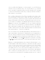
A C++ multithreaded architecture was proposed
for processing the brain and camera input and sending the right instruction to the intended appliance.
The architecture is shown in figure 1.
Fig. 1. Software architecture
Two data flows towards the controller thread can
be discerned. The first one shows the flow of the
camera input, starting at the camera thread. This is a
simple thread that merely acquires frames from the
camera and passes them on to a FIFO buffer called
the frame buffer. In order to capture these frames,
it makes use of a computer vision library called
OpenCV. The frames in the buffer are subsequently
fetched by the computer vision thread. This thread
uses OpenCV methods to perform object recognition on the newly collected frames by means of LBP
(Local Binary Pattern) cascade classifiers. The data
flow ends with the CV thread passing on the identifier of the recognised appliance that is most centrally
located in the frame, to the controller thread. Only
the centermost object is considered because, since a
user can’t interact with two appliances at the same
time, this is most likely the target appliance.
The second data flow starts with the Emotiv thread
collecting brain input (e.g. a boolean indicating that
the user is smiling) from the Emotiv headset. The
useful data is put into a self-defined struct containing the relevant detected brain inputs together with a
timestamp. This struct is handed directly to the controller thread.
The controller contains two intelligent data structures, one for the object identifiers and one for the
brain inputs, that are constantly updated using the
incoming data. The updating procedure for both includes incrementing a counter for the detected identifier and brain inputs (starting from one for newly
detected input) and removing data that has become
outdated (i.e. has not been detected for a predefined amount of time). Only when the counter has
reached a certain threshold level, the input is considered relevant. The only difference between objects
and brain inputs is that while several brain inputs
can be considered relevant simultaneously, there can
only be (at most) one single relevant object (called
the king object) at a certain instant. Once another
object crosses the relevance threshold, the old king
object gets ‘dethroned’. This relevance check together with the clean-up of outdated data guarantees that the considered data isn’t a spurious false
detection, but an up-to-date and relevant one. The
presence of a king object and a relevant brain input
causes an instruction to be sent to the IoT appliance,
being an empty instruction if the device doesn’t support that certain brain input. Once the instruction is
sent, the relevance counter of both the brain input
and the king object is set zero, thus ‘dethroning’ the
latter.
As mentioned above, not all Emotiv data is equally
useful. The only intent-controlled brain signals that
can be retrieved without needing to train the headset
are signals caused by facial expressions. Unfortunately, even within this class of facial expressions,
not all are usable for the purpose of controlling devices (e.g. not all people are capable of winking).
Therefore only smile, look left/right, raise/furrow
brow and clench are supported by the described system.
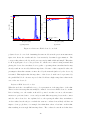
ing the wet electrodes by dry polymer ones, profound measurements were conducted to characterise
the behaviour of both. The results showed that the
equivalent impedance of the dry electrode and the
dry skin is more than one hundred times bigger in
amplitude for low frequencies than the combination
of a wet electrode and moistened skin. As these
low frequencies (0 to 100 Hz) are the frequencies
of interest for an EEG system, the correcting circuit should be able to lower the impedance seen by
the measuring device by a factor of more than 100.
Instrumentation amplifiers, voltage buffer op-amps
and a common drain transistor were considered as
possible solutions. Several were compared at power
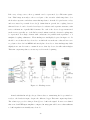
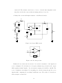
consumption and input impedance, eventually leading to the choice of the OP07 op-amp. This amplifier was simulated in the circuit shown in figure 2.
From left to right one can see:
• A series arrangement of a voltage source, a resistor and 2 parallel RC blocks representing the
potential generated by the body and the combined
impedances of both the dry electrode and the skin.
• A series resistor to prevent harmful currents from
entering the body.
• Two capacitors shorting high frequency noise to
the negative power supply and a bootstrap resistor
preventing the high input impedance from degrading.
• The OP07 itself with its ±3.7 power supplies,
which are decoupled by a capacitor.
• A simple first order low-pass filter formed by a
resistor and a capacitor. This filter has its cut-off
frequency at 500 Hz in order to eliminate high frequency noise at the output.
• A 1M Ω resistor representing the input impedance
of the Emotiv headset.
III. U SER TESTS
To test this software design, user tests were conducted. A group of voluntary test users was asked
to try controlling a Philips Hue lamp by looking at it
and performing certain facial expressions. The user
tests brought up two important remarks. First of all,
most of the users requested some sort of feedback,
telling them for example whether or not an object
was recognised and thus ready for being controlled.
Secondly, the Emotiv headset proved to be very user
dependent. Some users could apply all of the brain
inputs, others most but not all and some only very
few due to a wrong fitting of the headset to their
scalp.
IV. H ARDWARE
In order to design a proper circuit that is capable
of counteracting the change in signal when replac-
Rpr
Rlp
Re
Ce
3.7 V
−
Cdc
+
Rsc
Csc
Clp
-3.7 V
Chf b1
RB
Rbs
Chf b2
Vbp
Fig. 2. Active EEG circuit
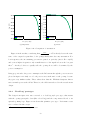
As these simulations gave very satisfying results,
the performance of a dead-bug prototype was tested
with specialised equipment for generating and measuring EEG signals at µV level. These tests proved
the correct functioning of the circuit, even at very
RZEmo
low level voltages. Unfortunately, the ultimate test
of using the correcting circuit to connect dry electrodes to the Emotiv headset couldn’t be performed
because the dead-bug prototype was infeasible for
this purpose and the PCB prototype is still in production at the time of writing.
V. C ONCLUSIONS
Both the software and hardware solution were
limitedly tested and were found to perform quite satisfying. However, future work could still improve
the system greatly. First of all, user-friendliness
would increase noticeably by introducing some kind
of feedback to the user, telling him for example
whether or not an object is detected. Secondly,
to make the system applicable in real-life environments, the number of supported IoT devices should
be greatly extended. Another flaw in the system is
that, at this point, it cannot support multiple appliances of the same type (e.g. 2 identical TVs in the
same house): each type of object has one identifier,
so duplicates are indistinguishable. Lastly, the PCB
version of the correcting circuit should be integrated
into the Emotiv headset to fully test its performance.
Contents
1 Introduction
1
1.1
Problem definition . . . . . . . . . . . . . . . . . . . . . . . . . . . . . . . .
1
1.2
Thesis goals . . . . . . . . . . . . . . . . . . . . . . . . . . . . . . . . . . . .
4
1.2.1
Software . . . . . . . . . . . . . . . . . . . . . . . . . . . . . . . . . .
4
1.2.2
Hardware . . . . . . . . . . . . . . . . . . . . . . . . . . . . . . . . .
5
1.2.3
Full system . . . . . . . . . . . . . . . . . . . . . . . . . . . . . . . .
5
2 Design and implementation
2.1
2.2
7
Software . . . . . . . . . . . . . . . . . . . . . . . . . . . . . . . . . . . . . .
7
2.1.1
Design . . . . . . . . . . . . . . . . . . . . . . . . . . . . . . . . . . .
7
2.1.2
Implementation . . . . . . . . . . . . . . . . . . . . . . . . . . . . . . 19
Hardware . . . . . . . . . . . . . . . . . . . . . . . . . . . . . . . . . . . . . 37
2.2.1
Research . . . . . . . . . . . . . . . . . . . . . . . . . . . . . . . . . . 37
2.2.2
Measurements
2.2.3
Design en simulation . . . . . . . . . . . . . . . . . . . . . . . . . . . 47
2.2.4
‘Dead-bug’ prototype
2.2.5
Printed circuit board . . . . . . . . . . . . . . . . . . . . . . . . . . . 55
. . . . . . . . . . . . . . . . . . . . . . . . . . . . . . 39
. . . . . . . . . . . . . . . . . . . . . . . . . . 52
3 User tests
59
3.1
Test set-up . . . . . . . . . . . . . . . . . . . . . . . . . . . . . . . . . . . . 59
3.2
User feedback . . . . . . . . . . . . . . . . . . . . . . . . . . . . . . . . . . . 62
4 Conclusions and future work
65
4.1
Conclusions . . . . . . . . . . . . . . . . . . . . . . . . . . . . . . . . . . . . 65
4.2
Future work . . . . . . . . . . . . . . . . . . . . . . . . . . . . . . . . . . . . 66
i
Bibliography
69
ii
Chapter 1
Introduction
1.1
Problem definition
The Internet of Things (IoT) is constantly gaining in importance. It encompasses an everincreasing amount of ordinary, everyday objects, all of them connected to the Internet.
The driving force behind this trend is the motivation to make life easier by interconnecting objects from our everyday environment with the Internet and optionally each other.
These interconnections not only introduce a new kind of intelligence that enables devices
to expand their data sources, but also make them capable of controlling or being controlled by remote devices. As a consequence of these new capabilities, an extremely wide
range of new features can be added to devices, going from a toaster showing the weather
forecast on a toast to a microwave that changes the color of the lamps when dinner is ready.
Internet of Things devices around the house can be configured to run automatically, given
a set of rules. For example, a coffee machine could automatically start brewing coffee in
the morning, or a printer could automatically order new ink cartridges when it’s running
low on ink. Oftentimes though, direct control by human users will be necessary. One
could, for example, wish to change the setting of the thermostat, change the TV channel
or even remotely consult the fridge’s content. These situations are, unfortunately, plagued
by the so-called ‘basket of remotes’ problem. Essentially, it means that not all things in
the IoT adhere to the same set of standards or protocols concerning communication. As
multiple protocols compete to become the standard, the IoT devices cannot be controlled
1
via a single remote (based on a single protocol). This leads to a ‘basket of remotes’, meaning that each appliance only communicates with its own, dedicated remote. Furthermore,
in order to control such appliances, a network connection needs to be set up. Without a
framework to group several IoT-devices, this manual setup needs to be performed for each
appliance in the user’s environment.
The problem described above could be solved by creating an application that incorporates
a universal interface for all these network-connected devices, which greatly improves the
user-friendliness. The user-friendliness could be further enhanced by making this system’s
inputs intent-based. The application should then automatically connect to IP-connected
appliances, and subsequently send certain instructions, based solely on the user’s intent.
Accurately retrieving the user’s intent is obviously critical for the correct functioning of
this system.
For the purpose of such an intent-based system, a brain-computer interface device is
needed. Such a device could be a headset that can measure EEG and/or EMG-type brain
activity (electroencephalography and electromyography, respectively). EEG readings measure the brain activity along the scalp, while EMG readings represent the electrical activity
of the underlying muscles. At present, a number of competing EEG headset devices are
commercially available, such as those from Emotiv or NeuroSky. The headset used in this
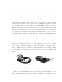
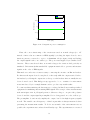
thesis is the Emotiv EEG system, shown in figure 1.1. This headset is marketed as a high
resolution, 14-channel, wireless portable EEG system. As the name implies, the headset
is intended to register EEG-type signals, but not the EMG-type. The matter at hand is
slightly more complicated though, and we refer to the hardware design section for more
in-depth coverage on the type of potentials measured by the headset.
Conceptually, such a headset device is capable of delivering the user’s brain activity to the
system. It should be noted though, that using only the brain activity from the headset
would be insufficient to fully determine the user’s intent. More specifically, it would remain
ambiguous which IoT-appliance the user wishes to contact. EEG monitoring technology
simply hasn’t advanced yet to the stage where this information could be extracted from the
brain. As such, a second device needs to be introduced for more complete intent detection.
2
This second device should be able to provide the system with a head-mounted video
capture. Because of the head-mounted nature of this camera, it is safe to assume the
video feed accurately shows what the user is watching (i.e. first person video). Through
object recognition, the software can keep track of which object the user is looking at, at all
times. This visual information is essential to know which IoT-appliance to contact, as we
assume the user only wishes to interact with the object he is currently looking at. It should
be noted that there are many different types of video capturing devices that could provide
the above functionality. The most basic device with this functionality would just be a
simple webcam, integrated in a pair of glasses. Such camera glasses would enable one-way
traffic, i.e. they would provide a video stream but they would not receive anything. As
an alternative, camera glasses incorporating a head-mounted display could be used (not
necessarily meaning augmented reality). This type of glasses could display information
concerning the system on the head-mounted display, directly in the user’s view. As yet
another alternative, augmented reality glasses could be used. Augmented reality glasses
can be either of the see-through or the non see-through variant. A non see-through pair of
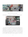
augmented reality glasses was made available for this thesis. The Vuzix Wrap 920AR, as
they are called, are shown in figure 1.2. To conclude the introduction on the video capture
device, it should be mentioned that in the future, the promising Google Glass could be
used too. Although they are not augmented reality glasses, they are sophisticated enough
to run the Android operating system, so they would introduce a lot of versatility in the
system.
Figure 1.1: Emotiv EEG headset
Figure 1.2: Vuzix glasses
It should be noted that this second device, by itself, wouldn’t allow intent detection
either. Using only the visual information would be insufficient, as it would not be clear
3
what the user wants to do exactly, unless the target device knows only one instruction,
triggered by looking at the device. In such a case, this would also imply that each time the
user gazes past the object, that instruction would be sent, regardless of the user’s intent.
With the above device descriptions, it’s become clear that using both devices is the only
way to reach a functional system. The cooperation and synergy between these two devices
enable a fully intent-based control scheme of IoT-appliances.
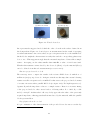
Returning to the Emotiv headset, though, another point of concern should be pointed
out. The Emotiv EEG system performs its measurements via wet electrodes (shown in
figure 1.3). These are essentially small felt pads, which need to be wetted with a saline
solution before they can be used. This solution is necessary to improve the signal pickup
from scalp to electrode. The first and most obvious problem is that these pads will dry
up while in use. The signal quality will deteriorate slowly but surely, and wetting again
will be necessary to continue. This takes time, is tedious and is not very user-friendly.
The wetness of the electrodes can also be experienced as uncomfortable by some users.
Furthermore, after each use, the electrode contacts need to be meticulously cleaned and
dried lest they corrode and, as a result, become unusable. In conclusion, although they
provide good conduction, wet electrodes are rather unfavorable for a user-friendly system.
To conclude the problem definition section, we point out that we’ve intentionally restricted
ourselves to the broad term ‘brain activity’, as the exact type of brain activity that will
be used is more of an implementation choice. As such, this issue is explored in the chapter
on design and implementation.
1.2
1.2.1
Thesis goals
Software
The goal of the software component is to develop a user-friendly, intuitively controllable
application that connects automatically to IP-connected appliances (unifying multiple
remotes from the basket) in order to send them instructions. These instructions are
determined by juxtaposing two types of user intent information: the brain activity is read
from the headset and an object recognition algorithm detects devices in the user’s field of
4
view. Special care will need to be applied while matching these inputs, as the user will
typically not wish to interact with objects that only appear for a few frames (i.e. when
he glances over the object).
1.2.2
Hardware
As for the hardware part, the goal is to replace the wet Emotiv electrodes by dry ones. We
have been provided with (dry) polymer electrodes, compatible with the Emotiv headset’s
fittings. These electrodes can be seen in figure 1.4. Because of their dry nature, these
electrodes carry weaker signals than the more conductive wet electrodes would. As such,
we had to design a PCB circuit that can process and ameliorate the signals, so that they
can still be correctly interpreted by the Emotiv headset, despite the use of dry electrodes.
Figure 1.3: Wet Emotiv electrodes
1.2.3
Figure 1.4: Polymer electrodes
Full system
The end goal of this thesis would be a fully functional system as described above. The userfriendliness of the system is of paramount importance, and is aided by three factors: the
intent-based nature, the hardware enabling dry polymer electrodes, and the elimination
of the basket of remotes. In the end, the purpose is to be able to have many people use
the system to control everyday IoT-appliances in a practical real-life environment. An
example of such an appliance, would be Philips Hue light bulbs, shown in figure 1.5. The
users could then use our system in an intuitive way to control the bulbs’ hue (or colour),
brightness, saturation and on/off state, using nothing more than their intent to do so.
A large factor in the assessment of the system’s success, will be the user-friendliness.
The user experience largely depends on ease of use: battery life, system latency and
5
Figure 1.5: Philips Hue light bulb
accuracy of intent detection all play a large role in shaping the user’s impression of the
system.
6
Chapter 2
Design and implementation
2.1
2.1.1
Software
Design
It probably goes without saying that a project of this size goes through several design
iterations before reaching the end result. In what follows, the two architectures the system
went through are presented. The second architecture will be seen to present solutions to
the shortcomings of the first. Before we present the actual system architectures, we begin
by laying out a high level, conceptual representation of the system. We don’t immediately
skip to the architecture designs because some aspects were present a priori, before any
actual design steps were taken.
Conceptual system representation
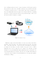
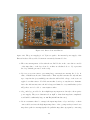
The initially devised schematic that groups the large building blocks of the prototype
system, is shown in figure 2.1. The prototype nature of this design is immediately visible
by noting the presence of the laptop. The task of this laptop is to communicate with
both human input devices. As both the Emotiv headset and the head-mounted camera
are intended to be worn by the user, these devices are characterised by their highly mobile
nature. This stands in stark contrast with the laptop, which is quite unwieldy to carry
around at all times. Because of this, the inclusion of the laptop in the conceptual representation might appear illogical. Incorporating the laptop, however, wasn’t completely by
7
choice: the Emotiv headset can only be contacted by means of a USB dongle. As such, a
laptop is indeed necessary, but it could still be stationary, set up somewhere in the same
room. However, the laptop needs to be carried around because of the second input device:
the provided Vuzix glasses deliver the captured video through a USB-cable, necessitating
the presence of a laptop near the user. In the prototype system, the laptop could be closed
and carried around in a backpack, for example.
Figure 2.1: System concept
Furthermore, figure 2.1 shows the inclusion of a remote server in the cloud. Indeed,
reiterating on the mobile nature of the envisioned system, the battery life of the system
will be of the utmost importance. As the battery life would lengthen by reducing the
processing load on the laptop, it would be useful to incorporate a server, to which a
significant portion of the processing load can be assigned. Note that this conceptual
schematic does not specify which functionality is implemented where, as that will become
clear in the final architecture description. After the server determines which instruction
corresponds to the user’s intent, it can send this instruction to the appropriate appliance
in the Internet of Things.
8
First architecture
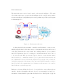
The first actual architecture, shown in figure 2.2, introduces several clear design choices at
the algorithm level. The first observation to be made, is that this architecture describes
a multithreaded application. It makes use of four continuously looping threads, summed
up below. The data structures used to communicate between threads are mentioned and
explained whenever appropriate.
Figure 2.2: First system architecture
• Camera thread
This thread contacts the head-mounted camera and retrieves a video stream at a
certain fps setting (frames per second). This thread is kept as simple as possible,
focussing only on video input acquisition. Each retrieved frame is then pushed to
the frame buffer. Note that, for now, this FIFO (first in, first out) buffer is not in
any way protected against infinite growth. In order to prevent this from happening,
the fps setting of this thread needs to be sufficiently low, so as to ensure that the
production rate of this thread is lower than the (average) consumption rate of the
following thread.
• CV (Computer Vision) thread
The computer vision thread’s first task is to take the frames acquired by the camera
9
thread. This communication happens via the (blocking) frame buffer. The blocking
nature of this buffer becomes apparent on the consumer side: if the queue is empty
when queried for a frame, the Computer Vision thread will wait until there is a
frame to pop. Once a frame is collected, it is subjected to an object recognition
algorithm. After each frame’s analysis, the objects that have been detected in that
frame are stored in a map container (the ‘Object Map’ in figure 2.2). This map
container is essentially a collection of key-value pairs, where the keys are simply
IoT-appliance identifiers, and the values represent (integer) ages. An IoT-object’s
age variable should be interpreted as the number of frames that have passed since the
last detection of that specific object. So, naturally, after a frame has been analysed,
this thread is also responsible for incrementing the ages of the map’s non-detected
objects by one, and resetting the ages of any detected objects to zero. In order
to keep this structure small and simple, objects with an age exceeding a certain
threshold are removed from the map (an infinitely increasing age isn’t very useful,
after all). Through this approach, the map is guaranteed to only contain recently
detected objects, with each age indicating just how recent the detection still is. This
map variable will be read by the controller thread (explained below).
• Emotiv Thread
Quite similar to the camera thread, this thread contacts the Emotiv headset and
retrieves so-called EmoStates. This data type, defined by Emotiv, contains all information pertaining to brain activity, as well as a timestamp. As the system doesn’t
require all of this information, it’s more efficient to continue working with a ‘filtered
version’ of the EmoStates. As such, a custom struct data type to collect all relevant
brain input was introduced. This struct will be explained in great detail in the implementation section, but we already mention its existence here to allow for easier
explaining of the algorithms in this section.
This thread has access to a blocking buffer (called the ‘Emo buffer’ in figure 2.2),
which implements a certain level of intelligence. The Emotiv thread pushes each
custom struct into this buffer, triggering a clean-up operation: each struct already
present in the buffer has its timestamp compared to the newly pushed timestamp.
Only if the resulting time difference is smaller than a certain threshold, the struct is
allowed to stay. As a result, this buffer is guaranteed to contain only the most recent
10
‘brain data’ structs. For example, the buffer could be set up to remove those entries
that occurred more than two seconds before the most recent entry. Similar to the
CV thread’s map container, this guarantee of recent data is an important property
for the further processing, in the controller thread.
• Controller thread
The controller block is where most of the system’s intelligence is implemented. In
short, it considers the inputs delivered to it by the Emotiv thread and the CV thread,
and tries to match them. In this context, a match is defined as a detected object
in combination with a detected Emotiv input it supports. Each of these matching pairs corresponds to a certain instruction to be sent to a certain device. Note
that not all IoT-devices are required to support the same set of Emotiv inputs: the
controller thread will need to know which devices support which inputs. In order
to acquire this knowledge, the controller not only needs access to a database that
holds this pairing information, but also to a mapping of matching combinations to
IoT-instructions. This database is not explicitly shown in figure 2.2, but its presence
is important and fully deserves to be mentioned in the text.
The matching is done by copying the data structures at the controller’s inputs (i.e.
the detected objects map and the Emotiv buffer) to deep copies, and iterating over
those in a pairwise fashion. Each match results in an instruction that needs to be
sent to the corresponding appliance. This matching procedure is what necessitated
the intelligence in the controller’s input variables. As stated above, these data structures hold not just one, but a number of recent entries, which enables the system
to cope with timing mismatches between the object detection and the brain input
detection. For example, in a system where only a single entry (of either input type)
would be presented to the controller, a match could be missed if the user applies a
certain brain signal, without having the software detect an object in a concurrent
frame. This situation is very plausible as the object recognition doesn’t have a 100
percent hit rate. Similarly, a user’s brain signal measurement could go wrong, causing the considered EmoState to be incomplete, with a missed opportunity to send an
instruction as a result. Furthermore, missed matches are possible in the case where
detection of either input is lagging behind a little bit. The implemented short term
11
memory is an effective way to handle these problems.
Sadly, the matching procedure didn’t turn out to be quite as straightforward as
described above. The system, as described above, didn’t have any way to invalidate
entries that have already been matched. Indeed, as the controller works with deep
copies of the communication variables, it cannot apply any changes to the original
version - such as removing the entries that caused the match, and subsequently,
caused the instruction to be sent. This had the unfortunate consequence that each
match caused a single instruction to be sent several times in rapid succession. This
happened because the matching pair will typically ‘survive’ in the buffers for several
iterations of the matching loop: they are only removed if their age exceeds a certain
threshold or when their timestamp occurred too long ago. As a result, instructions
were typically sent tens of times (with the exact number depending on the maximum
age allowed in the buffers). This is obviously not the desired behaviour. Colloquially,
we refer to this issue as the ‘spamming problem’.
The reason we opted for a multithreaded architecture, is the ability to independently
run several tasks at their own pace. For example, the threads responsible for input acquisition or object recognition shouldn’t be able to stall the main algorithm (i.e. the
matching in the controller), so these tasks were relocated to their own respective threads.
Another remark to be made in this regard, is that creating different threads for the frame
producer (camera thread) and frame consumer (CV thread) is not very useful without
intelligent management of the buffer in between them. For example, the fps setting could
be dynamically throttled when the buffer is seen to fill up faster than the consumer can
empty it.
A final remark we feel we need to make about this architecture, is that there is no return
path to the camera thread. This means that this system does not offer augmented reality.
The reason for this omission is that we decided to discard the provided Vuzix camera
glasses, because of its limited user-friendliness and poor ease of use when developing. In
order to provide proper augmented reality, the Vuzix needs to connect three cables to the
computer, making it very difficult to wear. As a pair of difficultly wearable augmented
reality glasses provides little extra value, we opted to replace them by a simple webcam.
12
Final architecture
The final architecture revision focussed entirely on the system’s intelligence. The main
idea of this revision was to group nearly all intelligence in the controller, and to further
increase its intelligence by implementing a few new algorithmic steps. The revised diagram
is shown in figure 2.3.
Figure 2.3: Final system architecture
At this point, the decision was made to run the controller thread to a remote server,
while keeping all others local. In this context, ‘local’ means the threads are still executed
on the laptop the user needs to carry around. One could argue that the object recognition
thread also implements quite a lot of intelligence, and that this thread could be moved
to the server as well. This option was not explored, however, because then the camera
thread would need to communicate with the object recognition thread via the internet. As
the communication between these threads comprises a steady stream of video frames, the
bandwidth requirements of the system would go up tremendously. Keeping the recognition
thread local, and only communicating object identifiers over the internet to the controller
thread is the more preferable approach.
Furthermore, the map holding the detected objects (and their corresponding ages) was
extended. As the reader might recall, each detected object was mapped to an age (i.e.
the number of frames that have passed since the last detection of that specific object). As
13
of this architecture, the map’s values (from the key-value pairs) are revised. Instead of
mapping objects to an age, they are now mapped to a pair of integers: the age alongside a
relevance counter. This relevance counter describes how many times the object has been
detected during the time it has been present in the map. This counter was added because
the object recognition algorithm sometimes produced false detections (i.e. it claimed to
detect certain objects, without them being present in the frame). Without a relevance
counter, the software would regard each reported detection as completely correct, including these false positives. Obviously, something is needed to differentiate between factual
detections and one-time, spurious false detections, and the relevance counter will play a
big role in the solution presented below.
This problem is tackled by the addition of a ‘king object’. Basically, the object map
now has the possibility to designate a ‘king’ among the objects it holds. First of all, the
map is updated after every processed frame in the same way as before. All objects in the
map will see their age increase by one. As before, non-detected objects exceeding the age
limit will still be removed from the map. A detected object will have its age reset to zero,
but now, it will also have its relevance counter incremented by one. Additionally, once an
object from the map has its relevance counter exceed a certain threshold, it is considered
the (one and only) king object. This guarantees that the king object was detected recently
(thanks to the age counter), but also that it has been detected several times in quick succession. This greatly reduces the chance of dealing with a false detection, as those typically
occur only for one or two frames at a time, with many frames in between them. Finally,
it should be noted that, at any given moment, there can only be one king object (or none
at all, of course). Furthermore, the object detection was modified to report at most one
detected object per frame: in those cases where multiple objects are recognised, only the
centermost object is pushed into the map as that one has a higher chance of actually being
intended by the user. As a result, a single frame can never promote multiple objects to
become king.
Now, instead of returning the entire object map when queried by the controller, only the
king object is returned, which is a lot more efficient. In figure 2.3, this algorithm is represented by the small crown above one of the map’s objects.
14
It should be noted that mapping objects to a pair of integers (i.e. the age in frames
and the relevance counter) equips the system with a remarkable robustness (provided the
thresholds assume suitable values), as both false positives and false negatives are barred
from being considered by the controller’s matching procedure. Both types of errors occurred when we explored object recognition algorithms, so steps had to be taken to deal
with these erroneous input events.
A false positive object detection would occur when the object recognition algorithm claims
to have recognised a certain object that’s not really present in the frame. This object could
never become king, though, as that would require a certain amount of detections, all following shortly after each other. In other words, the relevance counter can counter false
positives.
False negatives, on the other hand, occur whenever an object is being looked at directly,
but isn’t detected for a couple of frames. These missed detections don’t compromise the
correct functioning of the system though, because all objects in the map are allowed to age
a little before disappearing. As long as the correct detection kicks in again soon enough,
the map’s contents can survive for a few frames without detections. We conclude that the
age variable is able to counteract false negatives.
Furthermore, the addition of the object map’s relevance counter makes the system ‘glance
insensitive’. A likely event to occur while using the system, is that the user quickly glances
over a certain object, causing it to appear in a small amount of subsequent frames. That
doesn’t mean, however, that the user wishes to interact with that appliance. From an
object recognition point of view, recognising this object would qualify as a true positive,
but when considered from an intent-based point of view, this event would qualify as a
false positive. The relevance counter provides a means to ignore sufficiently short bursts
of object detections, as would occur when glancing.
The controller’s second input, the Emotiv data, is handled in a similar way. Because
of the inefficiency of having the controller copy the entire Emotiv buffer each time the
matching loop repeats, the Emotiv buffer was removed altogether. Inspired by the successful approach taken by the computer vision’s object map, the controller is given a data
structure (the details of which are given in the implementation section) to keep track of
the short-term history of Emotiv inputs. This data structure functions very similar to the
15
object map from above: for each possible brain input, the data structure remembers the
time it was last seen (i.e. a timestamp is saved), alongside a repetitions counter. Each
time a certain brain input is seen, its repetitions counter is incremented, and the saved
timestamp is updated accordingly (without passing the brain input through any kind of
buffer first). The repetitions counter is reset to zero, once too much time has gone by
since the saved timestamp. Once a brain input has accumulated sufficient repetitions, it is
considered relevant - but several brain inputs can be considered relevant simultaneously,
in contrast to the object map’s single-king approach. When the controller queries this
data structure, it will only take relevant inputs into account for the matching procedure.
Adding the extra complexity described above, is justified by considering the occasional inaccuracy of the Emotiv headset. Sadly, the headset doesn’t have a hitrate of one hundred
percent either. While we experimented with the headset, we discovered that sometimes a
brain input isn’t registered correctly (or even registered at all), or that sometimes a brain
wave pattern is detected that the user didn’t (consciously) apply. In short, the Emotiv
side of the system also has to deal with the problem of false positives and false negatives.
False positives are handled through the repetitions counter: a non-intended, spurious brain
signal won’t be able to reach the required number of repetitions before its time-last-seen is
too long ago. As a result, it will not be considered relevant, and the controller will ignore
this one-time, invalid detection. False negatives (i.e. a missed, but intentionally applied
brain input) can be handled by the saved timestamp: as long as the headset is able to
register that specific input again sufficiently quickly, its timestamp won’t have expired yet
and the repetitions counter can keep increasing without suffering a reset.
This concludes the description of the threads providing input to the controller thread,
and the variables through which this is done. All that remains now, is to shed light on
how the controller deals with these intent-based inputs. The controller thread uses an
infinite loop, which starts each iteration by querying the object map for the current king
object - if there is one. As this is a blocking call, the thread will halt execution until a
king object is found. As the controller now has a king object alongside a summary of
recent brain activity, it can iterate the brain inputs and verify which ones are considered
relevant. Choosing to wait for the object first, and iterate the brain inputs afterwards, is
16
a better approach than the other way around. Indeed, because retrieving the king object
is a blocking call, the controller loop is paused for the duration the user is not looking at
an IoT-appliance (which could be a long period of time). The brain inputs should only
be iterated after such waiting periods, so as not to rely on stale Emotiv data once a king
object is found.
Armed with the combined knowledge of which object the user is looking at, and which
brain inputs are applied, the controller can finally send the appropriate instruction to
the appropriate IoT-appliance. In the previous architecture, a database was required to
decide exactly what to send. For simplicity, this database was omitted from the current
architecture, and a different approach was taken. We refer to the implementation section
for a detailed explanation of this alternative approach.
Another aspect in which the controller improved, is the rate at which instructions are
sent. Indeed, the spamming problem is effectively solved by letting the controller interact directly with both of the short-term memory variables. Whenever a match is found,
the corresponding object is removed from the map and the brain input has its relevance
counter reset. This removal effectively prevents a single matching pair to send more than
one instruction. Furthermore, users won’t be able to apply certain brain inputs only once,
so the system will typically get to process bursts of the same, repeated brain input. Fortunately, not each of these repetitions will result in a separate sent instruction, thanks to the
relevance counter. Essentially, some sort of buildup is required: multiple repetitions get
aggregated to a single sent instruction, so this is another potential source of instruction
spamming which is now dealt with.
As should be clear by now, some parameters have been introduced that bear quite some
significance regarding the performance of the system. More specifically, the algorithms
introduced in this architecture rely heavily on the following four parameters:
• Maximum map age
This variable decides how long a certain detection needs to be remembered before
being removed from the object map. It defines a time-out of some sort: if no new
detection of the same object occurs within this many frames, the user most likely
17
isn’t looking at that object anymore and it’s safe to remove this object. Another
way to view this variable, is as the length of the short-term memory. By increasing
this threshold, the system becomes more tolerant of false negatives (detections that
should happen, but don’t), but the relevance counter will be somewhat undermined:
the idea of the relevance counter is to count the number of detections in a short
time span. If detections from too long ago are able to contribute to this counter, we
can no longer speak of short-term memory, defeating the purpose of having such a
counter in the first place.
• Maximum Emotiv age
This variable defines the limit of how long a brain input is allowed to wait for a new
occurrence. Similar to the previous parameter, this also imposes a time-out: without
a new occurrence of the same brain input, the corresponding repetitions counter is
reset to zero (analogous to removal from the object map). Again, in order to achieve
short-term memory, this variable should stay rather small. This time around, the
duration until time-out isn’t defined in number of frames, but in number of seconds
as each brain input is accompanied by a timestamp.
• Object map relevance threshold
This threshold is a measure of the system’s reluctance to accept object detections as
truthful. Before timing out, an object has to rack up at least this many detections
before the controller can consider it for matchmaking. If this value is too high,
the system becomes less responsive as the user would need to fix his gaze upon the
object for a longer period of time. If this value is too low, on the other hand, even a
small amount of spurious false positives could be registered as reliable, resulting in
a ‘wrongfully crowned’ king object.
• Emotiv relevance threshold
Similarly, this threshold indicates how many repeated occurrences are needed for
the controller to believe a certain brain input is truly applied. The consequences of
choosing this value too high or too low are quite similar to those from the previous
parameter. Still, this parameter differs from the previous one as it doesn’t have to
take the same value for each brain input. As the controller iterates the brain inputs,
it can use a different threshold to compare against for each brain input, as not all
18
brain inputs necessarily have to be treated equally.
Figure 2.3 clearly shows that this architecture still lacks a return path to the camera
thread. Indeed, as we continued development with the Logitech webcam, adding augmented reality to the system had become a task of low priority.
2.1.2
Implementation
First architecture
One of the first choices to be made, if not the very first, was to decide upon a programming
language. The language that was chosen, was C++, for a number of reasons:
• Emotiv interface
The communication interface with the Emotiv headset is provided through the Emotiv API (application programming interface). This API is exposed as an ANSI C
interface that is declared in 3 header files (edk.h, EmoStateDLL.h, edkErrorCode.h)
and implemented in 2 library files (libedk.so and libedk utils.so) [1]. For the sake of
completeness, we also mention that Emotiv provides a Java wrapper for this interface
as well.
• Computer vision libraries
The earliest research consisted of exploring several possibilities for the computer
vision libraries. Among those considered were BoofCV (for Java), SimpleCV (for
Python), Emgu CV (for all .NET compatible languages) and OpenCV (for C, C++,
Python and Java). We decided to go for OpenCV, because this library is very
mature and is frequently updated. As such, our implementation is not likely to rely
on deprecated libraries anytime soon, so choosing this library was the most logical
decision.
Given the two previous constraints, Java and C were other viable options, but weren’t
chosen.
A second implementation aspect was the operating system on which the system needs
to run. This was more of an initial constraint than it was a conscious decision: the
19
Emotiv headset at our disposal was purchased along with the Linux version of the SDK
(software development kit). As such, all development was done on the Linux platform.
Multithreading
One of the most notable features introduced of this architecture, was the practice of
multithreading. We’d like to remind the reader at this point that the threads introduced
so far were the Emotiv thread, the camera thread, the computer vision or CV-thread,
and the controller thread. As all development was done on the Linux operating system,
we were able to implement multithreading by means of POSIX threads, or Pthreads.
The method used to start up new threads is pthread create(...). Without going into
too much detail about this method’s exact signature, we mention that it’s possible to
pass arguments to the thread being started. This is useful whenever two threads need to
communicate via a (buffer) variable. For example, as the camera thread and the computer
vision thread communicate via the frame buffer, this buffer is declared in the main method
and subsequently passed to both threads. The same approach was followed for the buffer
holding the Emotiv data (between the Emotiv thread and the controller), and for the
object map (between the CV-thread and the controller). Indeed, as the controller of
the first architecture is still implemented as a local thread, it’s possible to keep these
communication buffers in shared memory on the same machine.
Emotiv thread
Another implementation element that quickly made its appearance, has to do with the
Emotiv headset. The Emotiv headset is delivered with several pieces of testing software
(the Emotiv Control Panel and the Emotiv Test Bench), which allow to investigate the
headset’s measurements. Using these, we can view (among other things) the electrical
waveforms of each of the fourteen channels, and the interpretation of the signals. Emotiv
has subdivided these interpretations in three categories, each of which has been cleverly
named, alluding to the company name:
• Cognitiv [1]
Cognitive actions are what most people immediately think of when presented with
the term ‘brain activity’. As Emotiv describes this category, the Cognitiv signals
represent the users conscious intent to perform distinct physical actions on a real or
virtual object. The detection is designed to work with up to 13 different actions: 6
directional movements (push, pull, left, right, up and down) and 6 rotations (clock-
20
wise, counter-clockwise, left, right, forward and backward) plus one additional action
that exists only in the realm of the users imagination: disappear.
A downside to this category of brain activity, is that cognitive concepts manifest
themselves differently on a person-by-person basis. As such, quite some training is
necessary in order to achieve precise detections of decent reproducibility. In addition
to training the ‘neutral’ action (the user’s passive mental state, not corresponding to
any intent), the user will need to sit through several training sessions for each of the
cognitive concepts the user wishes to use to control IoT-appliances. Each training
session requires the user to imagine or visualise the specific action for a duration of
eight seconds.
This presents a learning curve to the system (establishing a personalised signature or
profile for each user), but also to the user: maintaining their mental focus for eight
seconds to train the system is not always easy for a beginner. The headset’s manual
confirms this, by saying that it is common for novice users to become distracted at
some point during the training period and then mentally restart an action, but this
practice will result in poorer results than training with a mental focus that spans
the entire training period. They typically require practice to reliably evoke certain
mental states. Additionally, Emotiv warns to try to completely relax the face (i.e.
no head movements or facial expressions) as these actions can interfere with the
recorded EEG signal. This poses an additional difficulty during the training stage.
Furthermore, mental fatigue can set in after a while, deteriorating the reliability of
subsequent training sessions.
We decided not to support cognitive input in our system, as the required training
presents too big a hurdle. After all, the system we envision should be as user-friendly
as possible. Ideally, it should be an ‘out of the box’ system, meaning that it’s usable immediately, without any need for set-up or configuration (i.e. the training
process, in this case). Unfortunately, Cognitiv actions would lend themselves best
(compared to the following two categories) to being used for an intuitive mapping
to device instructions. In the trade-off between user-friendliness and intuitiveness,
21
user-friendliness was deemed more important.
• Affectiv [1]
Secondly, the Affectiv signals comprise the subjective emotions experienced by the
user. Examples of emotions that can be detected by the headset are excitement
(instantaneous as well as long-term), engagement, boredom and frustration.
A great advantage of Affectiv detections is eloquently described in the headset’s
manual: “the Affectiv detections look for brainwave characteristics that are universal in nature and don’t require an explicit training or signature-building step on the
part of the user”.
Obviously, this lack of required training is a very desirable trait because of the reasoning put forward in the Cognitiv discussion. Because of this, the Affectiv signals
deserve to be considered for the decision of which signal category our system will
support.
Unfortunately, this advantage is offset by the nature of affective brain activity. Indeed, emotional phenomena such as excitement or boredom are typically governed
by brain activity outside the user’s conscious free will. After all, users cannot, for
example, be asked to reliably feign a mental state of frustration in order to control an
IoT-appliance. As such, we quickly concluded that the headset’s Affectiv detections
are not suited for our intent-based system.
• Expressiv [1]
Expressiv signals represent the user’s facial expressions, measured via the EEG headset. The full list of Emotiv’s supported expressions are the following (in no particular
order): blinking, winking left/right, looking to the left/right, raising/furrowing the
brow, smiling, clenching, smirking left/right and laughing.
The Expressiv expressions manage to combine the benefits of the previous two contending categories. First of all, facial expressions can be performed on command,
with conscious intent, in contrast with the Affectiv emotions. Furthermore, each ex-
22
pression can also be withheld. However, the single exception to this rule, is blinking.
Indeed, as a user cannot simply cease blinking, not each blinking occurrence will be
the result of a conscious intent. Giving up on this single Expressiv expression is only
a small concession though.
Secondly, the Expressiv brain activity trumps the Cognitiv signals because training isn’t required for facial expressions. Training can be provided for Expressiv,
but it is optional. This is possible because the detection software of the headset
is equipped with a so-called ‘universal signature’, designed to work well for a large
population of users for the supported facial expressions.
Furthermore, as brought up earlier, Emotiv warns users to keep their face as still
as possible during the training process. If they don’t, which can occur even unconsciously, the training data will be contaminated with facial expressions. Also,
we noticed that the amplitude of the pulses corresponding to facial expressions is
a lot higher than that of any cognitive signals. That way, the system would be
indirectly trained to recognise facial expressions instead of the intended Cognitiv
actions. A simpler approach would be to cut out the middleman, so to speak, and
trigger directly on Expressiv detections.
To summarise, by pitting the three signal categories against each other, it becomes
clear that only the Expressiv category of brain activity is suitable to be used in an ‘out
of the box’ system. The lack of necessary training, and the fact that nearly all supported
facial expressions can be made consciously (and therefore guaranteeing an intent behind
it), form a combination that puts Expressiv ahead of both Cognitiv and Affective, for our
system.
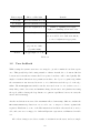
Now that a category of brain activity has been chosen, the logical following step is to
select a subset of Expressiv expressions to continue working with. The results of this
selection are displayed in table 2.1.
Special care should be taken with the ‘look left’ and ‘look right’ expressions. A detection of these expressions will be triggered when the user looks out the corner of his
eye. If the user would be looking at either side by turning his head rather than his eyes,
23
Expressiv expression
Supported? (Y/N)
Remarks
Look left/right
Y
Easy to do
Raise/furrow brow
Y
Easy to do
Smile
Y
Easy to do
Clench
Y
Very strong signals, easy to do
Blink
N
Sometimes involuntary
Wink left/right
N
Not everyone can do this
Smirk left/right
N
Could interfere with Smile
Laugh
N
Could interfere with Smile
Table 2.1: Selection of Expressiv facial expressions
the eye muscles wouldn’t be activated and the headset wouldn’t detect this expression.
Furthermore, if the user averts his gaze, the first person video capture wouldn’t focus on
the target IoT-appliance anymore. In short, the user should be made aware of the exact
meaning of these two expressions, as their name alone is somewhat ambiguous.
The Emotiv thread retrieves variables called EmoStates from the headset. Emotiv describes these variables as follows: “an EmoState is an opaque data structure that contains
the current state of the Emotiv detections, which, in turn, reflect the users facial, emotional
and cognitive state”. [1]. In order to keep things short and simple, the communication
between the Emotiv thread and the controller thread needs to be kept as minimal as possible. Specifically, this means it’s not necessary to push the entire EmoStates into the
buffer shared with the controller, because we ignore all Cognitiv and Affectiv detections,
as well as several Expressiv expressions. Because of this, a custom struct was defined,
containing only the information considered relevant:
typedef struct {
bool smilebool;
double smile;
bool clench;
bool frown;
bool raise eyebr;
bool lookL;
24
bool lookR;
double timestamp;
} Emo amplitudes;
The Emo amplitudes struct contains a series of booleans, indicating whether or not
the associated expression has been detected or not. In addition to these booleans, two
doubles are stored as well. The first one (timestamp) indicates the time of the detection,
given in seconds since switching the headset on. The second one, smile, represents the
degree (or amplitude) of the user’s smile, ranging from 0.0 to 1.0. Smiling more widely
will result in a higher value. The inclusion of this fractional value allows the system to
react in proportion to the extent in which the user is smiling. It should be noted, though,
that this value is only valid whenever the boolean smilebool is true.
OpenCV thread
In the OpenCV thread another implementation choice had to be made: the object recognition algorithm. Four different algorithms were considered, all included in the OpenCV
library: SURF (Speeded-Up Robust Features) feature recognition, SIFT (Scale-invariant
feature transform) feature recognition, cascade classifiers based on HAAR-like features
and cascade classifiers based on LBP (local binary patter) features. The first two search
for SIFT/SURF features (with features defined as distinguishable elements on an image)
in frames and try matching them to the feature description of an object they already know
while the latter two try matching what they see to several stages of HAAR-like/LBP feature descriptors (called classifiers), each stage being more restrictive than the previous one
(therefore called cascade classifiers). It should be stressed that choosing an appropriate
recognition algorithm was not the main goal of this master’s thesis and though no rash
decisions were made, it cannot be guaranteed that the best performing algorithm was
implemented.
The first one that could be excluded from the candidate list was SIFT because the standard version of SURF is claimed to be faster and more robust[2]. In a similar way, LBP
classifiers were found to outperform HAAR classifier both in speed of recognising objects
and in time needed to train the classifiers[3]. The price that has to be paid for this
speed improvement is a minor loss in accuracy, but considering the real-time aspect of
25
the application, minimising delay is more crucial. This narrowed the options down to
SURF or LBP. Though both perform well, the LBP cascade classifier method was preferred over SURF feature detection. The decisive arguments were its speed, the robustness
to illumination[4] and the fact that the classifiers can be stored in very compact XML files.
Like every object recognition algorithm, the LBP cascade classifier method works in two
stages: training and detection. For the training process, positive images (showing the
object to be recognised) and negative images (showing anything but the object to be
recognised) have to be supplied. A method called createtrainsamples[5] converts these
positive images to greyscale, deforms them slightly (by for example rotating or stretching
them) and puts them onto a random background, thus creating so-called samples. Note
that a single positive image can serve creating several samples. Some important arguments of createtrainsamples are presented below, together with some guidelines found
through trial and error:
• Positive images: refers to a text file that specifies where the positive images are
located. In order to create a proper functioning classifier, about one hundred of
these images are needed (at least).
• Background images: refers to a text file that specifies where a set of background
images is located. The same set of background images can be used for each classifier. As the only requirement is that they are random, the set of negative images
(explained in more detail below) can serve this purpose. An amount of around 3000
images proved to be sufficient.
• Number of samples: determines, as one could have guessed, the number of samples
that are produced.
• Background colour: allows the user to specify the background colour (on a greyscale
ranging from 0 to 255, representing white and black respectively), thus preventing
the classifier to include part of the background in its training. Note that this only
works for objects photographed in front of a (more or less) monochrome background,
after converting to greyscale. When only a small amount of background is visible
and there is no need for background reduction, this value can be left to zero.
26
• Background threshold: turns the background colour into a range of colours. Everything within the range [Background colour ± Background threshold] is omitted
for the further training. This efficiently deals with backgrounds that don’t have a
uniform greyscale value.
• Maximum x, y and z rotation angle: sets the maximum angle (in radians) over which
the image may be rotated in the x, y and z directions. The default values of 1.1, 1.1
and 0.5 respectively were found to perform well.
• Maximum intensity deviation: specifies the maximum intensity deviation of foreground samples’ pixels. The default value of 40 doesn’t require any altering.
• Width and height: allow the user to set the width and height (in pixels) of the
generated samples. This should preferably be chosen small, as training and detection
slow down very quickly as the sample size goes up. For an object with an aspect
ratio of 4:3 for example, 40 x 30 pixels is an appropriate sample size.
After the samples are created, the actual training starts. createtrainsamples returns
the generated samples for each positive image in a vector and these can be passed on to
the opencv traincascade method, after merging them to one vector file with a program
called Mergevec. Apart from this vector file, this method requires additional important
arguments:
• Background images: also called negative images, this refers to a text file specifying
the location where the negative images are located. Negative images should be
carefully selected to be as random as possible while guaranteeing that the images
never contain the object to be recognised. The more random the negative images
are, the more the classifier can guarantee that it won’t see the object when it’s not
present (i.e. false positives), while preventing the object from showing up in the
negative images makes sure that the classifier doesn’t get confused about what is
and isn’t the object (thus preventing false negatives). An amount 3000 negative
images was found to suffice.
• Number of stages: is the number of stages the cascaded classifier should contain.
The LBP cascade classifier method performs its searches for an object in an image
in several stages going from a quick scan to a thorough investigation. The more
27
stages, the more alike the object in the image has to be before it’s considered a
match.
• Minimum hit rate: defines the minimum ratio of all positive images tested in that
stage (with the classifier at that point) that should be correctly seen as a match. The
total minimum hit rate of the system should thus be M inimumhitrateN umberof stages .
A ratio of 0.999 leads to satisfying results.
• Maximum false alarm rate: is the maximum ratio of negative images tested (again
with the classifier at that point) that may be labelled as positive. This reduces the
maximum ratio of false positives to M aximumf alsealarmrateN umberof stages . Given
the amount of stages used (15), even a value of 0.5 gave good results.
• Number of positives and negatives: specifies the number of positive samples and the
number of negative images that should be used for every intermediate test. When
at a certain test the goal for either the hit rate or false alarm rate isn’t reached, the
method restarts its training for that stage with a slightly different set of positive
samples and negative images. Therefore these values should be somewhat lower
than the available samples and images in order to enable the classifier to meet the
envisioned hit and false alarm rate.
• Width and height: should correspond to those chosen for the sample size.
• Feature type: is chosen to be LBP (and not HAAR) for reasons mentioned above.
The output of the opencv traincascade method is a trained cascade classifier in the
form of XML files. These cascade classifiers can easily be loaded into a C++ program. To
recognise the objects in the current frame, the OpenCV thread acquires a frame from the
frame buffer and performs a detection on it for each available classifier. If an object is
detected, its identifier is passed on to the controller thread. Note that, as an object can
look entirely different from another perspective, several classifiers can be used as aliases
for the same object. The detection itself is performed by an OpenCV method called
detectMultiScale. This method too requires some arguments worth mentioning:
• Minimum and maximum size: determine what the smallest and largest scaled versions of the object are that are considered for the detection. One tenth and half of
28
the of the screen size respectively prove to be reasonable values. Note that the minimum size determines the maximum distance that an object can be removed from
the camera and still be recognised.
• Scale factor: specifies the factor by which the size of the object increases when going
from the minimum to the maximum size. A very small scale factor improves the
accuracy but slows the system down as it has to perform more detections. A good
trade-off between both when testing showed to be 1.1 .
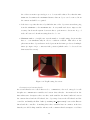
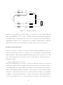
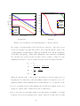
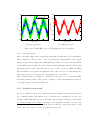
• Minimum number of neighbours: sets the number of neighbouring detections that
have to occur simultaneously in order to result in a match. This relies on the
phenomenon that objects that are indeed present in the frame get detected multiple
times (see figure 2.4) to counteract false positives (which tend to be detected less
than actual detections).
Figure 2.4: Neighbouring detections
Communication between threads
As several threads were added that need to communicate, the need emerged for well
thought-out communication variables in between these threads. As mentioned in the
first architecture description, there are three such variables: the frame buffer in between
the camera thread and the CV-thread, the object map between the CV-thread and the
controller, and finally, the Emo buffer (containing Emo amplitudes) between the Emotiv
thread and the controller. Something these three variables have in common, is the fact
that they are all blocking variables: whenever the consumer thread attempts to read data
29
while there is none, the thread will block (i.e. its execution is halted). The least complicated of these three variables is the frame buffer in between the camera thread and
the CV-thread. The blocking behaviour is implemented using condition variables, providing the additional benefit of a faster reaction time compared to a periodic wake-and-poll
approach. Whenever the CV-thread tries to retrieve a frame when there are none in the
frame buffer, it will enter a wait state using the frame buffer’s condition variable. The wait
state can be ended by another thread (in this case, by the camera thread), signalling that
the buffer is no longer empty. The CV-thread will wake and it can then resume normal
operation.
For this desired behaviour of the frame buffer, an excellent implementation can be found at
justsoftwaresolutions.co.uk [6], requiring practically no editing for our purposes. Their condition variable makes use of mutex (mutual exclusion) protection, relying on the renowned
Boost C++ libraries. A mutex is a concept often encountered when dealing with shared
resources between concurrent threads. In order to avoid race conditions, a mutex ensures that, during a thread’s critical sections, a shared resource cannot be concurrently
accessed by other threads. It should be noted that mutual exclusion is not very critical
in our single producer, single consumer set-up, but it certainly can’t hurt. As such, the
concurrent queue class was added to the project to implement the frame buffer.
One of the most important methods of this class, is the push method, given below:
void push(Data const& data) //reference passed!
{
boost::mutex::scoped lock lock(the mutex);
bool const was empty=the queue.empty();
the queue.push(data);
lock.unlock(); // unlock the mutex
if(was empty)
{
the condition variable.notify one();
}
30
}
The push method begins by locking the mutex variable, after which it determines
whether the underlying queue is initially empty or not. Next, the data (i.e. a frame in our
case) is pushed into the queue, and if necessary, the waiting thread is notified. The waiting
thread will wake, and will attempt to read the newly supplied data. The lock.unlock
statement is placed before notification statement, in order to allow the waiting thread to
immediately acquire the lock once it’s notified.
As both other communication variables share this fundamental blocking behaviour with
the frame buffer, they were implemented by simply adapting the already implemented
concurrent queue. In the case of the object map, a new class (called the ObjectMap) was
created by replacing the frame buffer’s underlying std::queue<Data> with a std::map
<std::string, int>. The std::string key represents the object’s IP-address (preferably IPv6), while the int serves as the object’s age (i.e. the number of frames that have
passed since the last detection of that specific object). Furthermore, the push method
was renamed to ObjectMap::rejuvenate or add and was extended with some necessary
intelligence. The method only adds the detected object’s IP if it is not yet present, and otherwise, the already present age is reset to zero (i.e. the rejuvenation). A notification is still
sent when the map stops being empty. Additionally, the ObjectMap::age up and clean
method was introduced, which needs to be called after every processed frame, regardless
of whether or not an object has been detected. This method increments all ages in the
map, and removes the objects that became too old.
Similarly, the blocking buffer containing the Emo amplitudes is an adaptation of the
frame buffer, called the EmoBuffer class. The first difference is that the push method was
expanded to become age push: any time an Emo amplitudes struct is pushed, the structs
already present in the underlying std::vector are removed if their timestamp differs too
much from the newly pushed one. The second difference is that the EmoBuffer doesn’t
return a single value when queried, but the entire underlying std::vector.
To conclude the discussion on the implementation of the first architecture, it should
be noted that a database was mentioned in the architecture description. This database
needed to inform the controller of which input combinations (i.e. a combination of an
31
IoT-appliance with an Expressiv expression) lead to which instruction. This database was
implemented as a simple text file, following a certain self-defined syntax. At the start-up
of the controller thread, a method was called to parse this text file, and load its data into
a static variable of the controller.
Final architecture
For this architecture, special attention was devoted to the idea of a remote server, hosting
the controller process. All variables and methods needed in the controller process are
collected in the Controller class. As this process would be run on a different machine
entirely, there is no longer shared memory between the controller process and the other
threads. The previous architecture, in contrast, described several threads in the same
process, so shared memory could be used for communication between any two threads. As
such, only the frame buffer is still a variable in local shared memory (between the camera
thread and the CV thread).
Because the Controller no longer shares memory with the local threads, the ObjectMap
was moved into the Controller class, as a static variable. Note that the EmoBuffer wasn’t
moved, but removed entirely as explained in the design section on this architecture.
As of this architecture, the map’s key-value pairs are revised: both the keys as well as the
values are implemented differently. The value is no longer an int , but a std::pair<int,
int> to accommodate both the age and the relevance counter. Secondly, whereas the key
(or object identifier) used to be an IP-address, it has now been changed to an object ID.
The reason for this change becomes apparent when one considers a scenario where a user
has multiple instances of a single type of device (e.g. multiple Philips Hue light bulbs in
different rooms). As each of these duplicate devices has the same physical appearance,
the object recognition algorithm cannot determine which one it is currently seeing. As a
result, the needed IP-address remains unknown. It can, however, supply a device ID for
the recognised device type. In order to differentiate between the possible candidates, an
extra, complimentary input would be needed. This input could, for instance, take the form
of a location specifier such as GPS. However, as our system doesn’t have this extra input,
we had to ensure that duplicate devices differ sufficiently in appearance (e.g. a different
32
socket for each Hue bulb). Furthermore, a decision was made to store the IP-address in
a sub-field of the reported ID. By doing so, the controller will need to process the ID
in some way (instead of immediately using it as the IP). Currently, the IP can simply
be extracted from the ID itself, but this extra processing step lends itself excellently for
future adaptation to an extra input.
The object IDs are implemented as follows. They are essentially a std::string, containing several substrings (or fields) separated by slashes. The first field contains the name of
the device type that was recognised in the several previous frames. The Controller will
always read the first field, but the amount of following fields depends on the exact device
type. For instance, the identifiers for the Philips Hue light bulbs take the following form:
HUELAMP/10.10.129.100/2. Here, HUELAMP is the device type, which the Controller
knows to have two more text fields. The second field is the IP-address of the Philips Hue
Bridge, which is shared by multiple bulbs. The distinction between the bulbs is made by
the Hue id, which is 2 in the given example. With this information, the Controller has
all necessary information to contact the second light bulb.
Next, a new class was created, called EmotivRecentHistory. The Controller class contains one static instance of this class, used to implement the protection against false positives. For each supported Expressiv expression, the EmotivRecentHistory class stores a
double time last seen and an int repetitions. As this variable needs to stay up-todate, each time the server receives an Emo amplitudes struct, it updates the corresponding
time last seen variables and increments or resets the appropriate repetitions counters.
Furthermore, the EmotivRecentHistory class contains an additional double, to store
the smile amplitude. This variable is taken into account whenever the smile repetitions
counter exceeds the relevance threshold. As such, the instruction paired with the smiling
expression can take this value as an argument, enabling a reaction proportionate to the
user’s smiling extent. Note, however, that only the latest smiling extent is taken into account. For example, if the relevance threshold is three, then the first two smile amplitudes
will be overwritten before the third repetition can ever be reached. As the controller ignores expressions below the threshold, the only smiling extent that can ever be considered
33
behaves a lot like the proverbial straw that breaks the camel’s back.
The Controller’s matchmaking loop counts on both the EmotivRecentHistory and the
ObjectMap to contain up-to-date summaries of the short term input history. As these
variables are now located in the Controller class as static variables, they are no longer
directly accessible by (or even visible to) the threads providing the input (i.e. the CVthread and the Emotiv thread). In order to tackle this problem, the Controller was
equipped with three static methods providing access to these variables, earning them the
name of access methods:
• void update erh controller(Emo amplitudes ea)
• void age up and clean controller()
• void rejuvenate or add controller(std::string ID)
Each of these methods calls the corresponding method on the Controller’s short-term
memory variables (i.e. the methods without the controller suffix). Next, these methods should be able to be called by the producer threads. This client-server behaviour was
implemented using the RPC concept (remote procedure call). The RPC concept allows
a local thread (e.g. the CV-thread or the Emotiv thread) to call a method as if it were
implemented locally, whereas in reality, the called method is defined and run remotely on
a server hosting the RPC service implementation. These methods form the bridge between
the local system (the laptop) and the server, and as such, we call these the remote methods.
As there are three access methods, three remote methods to call them are needed. The
framework used to define and implement the RPC functionality, is called Apache Thrift.
The controller process on the server deals with the RPC implementation as follows. First
it starts its own permanent thread (the Controller thread, as earlier), and then it goes
to listening mode. It begins listening for incoming RPC requests, and runs the desired
method in a separate, newly created thread. This way, the controller loop looking for input matches isn’t disturbed by the input providers. Whenever the controller loop queries
either input, it can be certain that the data it gets is kept recent because the updating is
performed in separate, temporary thread, created at the initiative of the threads providing
34
the input. Furthermore, race conditions are impossible as the variables to be updated (the
ObjectMap and the EmotivRecentHistory) are written and read using mutex protection.
An immediate advantage of running the Controller on a server, is that the user no
longer needs to carry the entire system around. As the Controller’s code is executed
elsewhere, the battery life of the mobile platform can be expected to be longer, which is
undoubtedly a boost for the user-friendliness.
Finally, as the database from the previous architecture didn’t make it into the current
one, a different approach was necessary to link each matching pair (of an IoT-appliance
with an Expressiv expression) to an instruction to be sent. This linking procedure was
implemented using a Factory class. What this means is that the Controller will use
its retrieved king object to create an instance of a generic base class (the IotAppliance
class) using the following method call:
Factory::create appliance instance(current object ID), where
current object ID is a std::string, as mentioned above. This method implements a
switch-case statement on the object’s ID to decide which subclass to return an instance
of. For each Internet of Things device type we wish to support, an new class needs to be
added that inherits from the IotAppliance base class. For example, the derived classes
we implemented are the LoopBackConsoleAppliance class and the HueLamp class. As a
side note, the former was merely used as a proof of concept during development before we
had access to the Philips Hue lights. It corresponds to a terminal on the local machine,
providing textual output describing the detected Expressiv expression while the user is
looking at the machine.
The IotAppliance base class has a virtual method for each supported Expressiv expression, which is overridden in each of the inheriting classes. The big advantage of using
virtual methods, is that whenever they are called, the most-derived version will be executed. As the base class’s virtual method implementations are left empty, each inheriting
class can choose which Expressiv expressions to support, by only overriding that subset of
methods. If a derived class doesn’t provide an overridden implementation, the base class’s
version will be called, with does nothing at all as it has an empty body.
35
The overridden methods in the HueLamp class need to contact the Philips Hue Bridge
using HTTP PUT requests, as part of a RESTful interface. To implement this functionality, curlcpp was used, which is an object-oriented C++ wrapper for the libcurl library.
As the Controller receives a derived instance of the base class from the Factory, it
can simply call the appropriate methods (once for each expression over the repetitions
threshold) without needing to know exactly which derived class it’s dealing with. The
need for a database of supported matches and their corresponding instructions, as in the
previous architecture, is now entirely eliminated.
A final note about the Factory, is that it needed to be equipped with memory to keep
track of already instantiated devices and their associated parameters. Without this kind
of memory, the Factory would respond to each instance production request by calling a
constructor of a derived class, initialising all device parameters to a default value. This
would essentially mean that each time the user looks at a device long enough to have it
become the king object, its parameters would all be reset to default. For the Philips Hue
lights, for example, these parameters are brightness, hue, saturation and on/off state. How
these parameters are controlled by the Emotiv events, is detailed in the set-up section of
the chapter on the user tests.
This explains the addition of a static std::map<Object ID, IotAppliance*> memory
variable to the Factory. When the Factory is asked to provide an instance of a device
already instantiated once before, it can simply pull up this instance from the memory,
keeping its parameters intact instead of supplying them with default values.
36
2.2
2.2.1
Hardware
Research
As has been made clear in the thesis goals, the purpose of the hardware part is to preserve the correct functioning of the Emotiv headset, when replacing the wet electrodes
by their dry polymer counterparts. As the dry electrodes are very probable to increase
the impedance the Emotiv headset experiences when performing its measurements on the
user’s head, the introduction of a correcting circuit lowering this impedance should most
likely be able to compensate for the use of dry electrodes. But because unfounded assumptions are a very bad basis to start from, a profound research was conducted before
commencing the design of the correcting circuit.
For correctly understanding which differences the Emotiv headset experiences when using
dry electrodes, a good insight in the nature of the signals that are measured is needed.
Though Emotiv claims to measure EEG (electroencephalographic) signals [1], in fact the
signals entering the headset before being processed can be more generally classified as
biopotentials. Biopotentials -being nothing more than a voltage produced by a tissue of
the body- are often referred to with more specific names, depending on what the signals
represent. When recording the brain’s activity along the scalp they are named electroencephalographic (EEG) signals but when for example they correspond to muscular activity
they are labeled electromyographic signals or electrocardiographic signals for displaying
heart activity. As facial expressions (e.g. frowning) induce EMG signals that can be intercepted at the scalp as well [7], the headset picks up not merely EEG signals but also other
biopotentials. The exact interpretation of the biopotentials can be left in the experienced
hands of Emotiv, what is of most importance when designing the system is that the headset acquires potentials. However, what does matter is that the Emotiv software can only
acquire signals up to 64Hz. Considering some margin, this means that the desired system
only has to pass the potentials lower than about 100 Hz and consider signals higher in
frequency as noise. The Emotiv measuring software showed that the EEG signals were
not only limited in frequency range, but also in amplitude range, going from a few µV to
some hundred µV .
37
Like every voltage source, these potentials can be represented by a Thévenin equivalent. This brings us neatly to the second part of the research: which impedance does
the headset experience and what causes this impedance? A methodological review on dry
and noncontact biopotential electrodes [8] claims that in general, the coupling between
skin and electrode can be described as a layered conductive and capacitive structure, with
series combinations of parallel RC elements. For each of the electrode types mentioned
in the review, typically one of the RC sections dominates and the electrical coupling may
be represented as a single element with conductance in parallel with capacitance or a
simplified coupling admittance. Their findings are intelligibly depicted in figure 2.5. It
should be noted that the dry electrodes on which the research was conducted here were
no polymer electrodes but MEMS and metal plate electrodes so these findings may differ
slightly from ours. It is safe to assume however, that dry electrodes will result in higher
Thévenin output impedances, as was expected from the beginning.
Figure 2.5: Findings review
Armed with this knowledge, the problem reduces to transferring the biopotential correctly to the headset’s input, despite the different, bigger Thévenin output impedance.
The solution proposed for this problem [8] is to buffer the signal. It was even claimed
that a modern FET-input amplifier configured in unity-gain will be more than sufficient
to buffer signals from virtually any electrode.
38
2.2.2
Measurements
In order to design an appropriate correcting circuit, a good model for representing these
impedances shows itself a useful tool. Therefore the next step conducted in the design
process was measuring the impedances of several electrodes on both skin and a wet cloth.
The exact procedure as well as the results are presented below.
Measuring procedure [9]
The impedance measurements were performed at Imec Leuven with the CompactStat
portable electrochemical interface and impedance analyser. The CompactStat uses fourpoint sensing to determine impedances. This implies that measurements are carried out by
using four electrodes: the working (WE), counter (CE), sense (S) and reference electrode
(RE). The configuration of these electrodes for the measurement arrangement can be seen
in figure 2.6b and 2.6a. Impedance measurements are executed by forcing current from
the working to the counter electrode and measuring the induced voltage from reference to
sense electrode. For this specific case, this results in a schematic diagram as depicted in
figure 2.7 because the working and sense probe are shorted. The abbreviations used are
quite intuitive: R∗W represents the parasitic resistance in each of the probe wires, Z∗E
the impedance of each electrode and Zmat∗ the impedance of the material connecting the
different electrodes.
(a) Configuration on arm
(b) Configuration on cloth
Figure 2.6: Arrangement impedance measurements
As the sense and reference electrode merely measure voltage and don’t conduct any
current, no voltage drop is generated over neither ZRE , RRW nor RSW . This means that by
determining the relation between the measured voltage and the forced current, the series
39
RW W
Itest
WE
ZW E
Itest
S
RSW
Zmat1
Vtest
RRW
ZRE
RE
Zmat2
Zmat3
Itest
CE
RCW
ZCE
Figure 2.7: Schematic diagram
impedance of ZW E and Zmat1 is found. As Zmat1 is expected to be low (because S, WE and
RE are physically placed close together, see figure 2.6a and 2.6b), the measured impedance
is primarily ZW E . Consequently, the electrodes to be tested were used as working (or
equivalently as sense) electrode. It should be noted that for measurements on skin, the
impedances introduced by the skin layers are included in the electrode impedances.
Results and interpretation
Tests were performed on 4 types of electrodes (reference ECG, (wet) Emotiv sponge, dry
polymer and metal pin electrodes, see figure 2.8) on two materials (cloth and skin) at
different distances. The relevant results and their interpretation are presented below. The
tests on the metal pin electrodes aren’t enclosed because they are of little importance to
this master’s thesis.
Reference ECG electrode on cloth
All of the measurements on cloth were conducted both with a spacing of 4 and 8 cm
between the counter electrode and the other electrodes. However, because the results of
both arrangements were quite similar, the results of the 8cm spacing arrangement are
omitted. This negligible difference shouldn’t come as a surprise, as increasing the distance
between the counter and the other electrodes only increases Zmat3 in figure 2.7 and thus has
no influence on the measured impedance. To start off easy, figure 2.9 shows the impedance
of the reference ECG electrode on cloth. In this plot, and all of the following, the red
40
(a) Reference ECG
(b) Wet sponge
(c) Dry polymer
(d) Metal pin
Figure 2.8: Tested electrodes
line represents the suggested model, while the other colors show the values obtained from
the CompactStat. Figure 2.9 doesn’t depict one measurement but the result of averaging
several measurements. One can see that, except for frequencies far above the 100 Hz noise
threshold, the amplitude characteristic is nearly flat∗ and the corresponding phases stay
close to zero. This suggests strongly that the measured impedance behaves like a simple
resistor. Averaging out the values smaller than 1000 Hz, a value of 512 Ω was found.
Whether this resistance is introduced by the electrode (ZW E ) or by the material (Zmat1 )
can’t be deduced from this sole measurement (see section 2.2.2).
Emotiv sponge electrode on cloth
The next step was to compare the results of the reference ECG electrode with those of
an Emotiv (wet) sponge electrode. As figure 2.10 shows, this impedance starts behaving
resistive as well for frequencies above 100 Hz. For that reason, the proposed model consists
of a resistor in series with a parallel RC block (see figure 2.11). For high frequencies, Cp
bypasses Rp and the impedance reduces to a simple resistor. Brute force iterative fitting
of the proposed model to these curves leads to following values: R = 516Ω, Rp = 5kΩ
and Cp = 46.1µF . As this value for R very closely approaches the value of the previously
acquired impedance, this suggests that R is introduced by the material, while the parallel
block represents ZW E .
Dry polymer electrode on cloth
A logic continuation of the characterisation of the provided electrodes was to test the dry
∗
Note that the y-axis starts from 50dB.
41
120
Average values
Model
0
110
Phase (rad)
Amp (dB)
100
90
80
−0.5
−1
−1.5
70
60
−2
0
10
2
10
Frequency (Hz)
Average values
Model
0
4
10
10
(a) Amplitude
2
10
Frequency (Hz)
4
10
(b) Phase
Figure 2.9: Reference ECG electrode on cloth
polymer electrode on a cloth. Assuming the same model as in the previous measurement,
figure 2.12 shows the results and the best iteratively determined approximation. The
corresponding values for R, Rp and Cp are respectively 400Ω, 1M Ω and 700µF . This value
for R is again quite close to the previous one, all the more when bearing in mind that
placing the electrodes somewhat closer together or pressing them somewhat harder may
already result in a noticeably different impedance. Because of this comparable value, the
presumption that this resistance is introduced by the material (and not by the electrode)
is fortified. This implies that the impedance of the electrode itself can be represented by
the parallel RC block. As was expected, this block has a higher impedance than in the
case of the wet electrode.
Reference ECG electrode on skin
What the models so far still lack, is a good representation of the impedance of the skin.
Therefore the next setup that was analysed consisted of a reference ECG electrode on skin.
Before heading on to the results, it should be pointed out that once more, the measurements were performed twice: on two subjects with different spacing between the counter
and the other electrodes. As explained above, the spacing shouldn’t have an influence
on the results, but the subject on which the tests are conducted most likely will have an
impact. Some people have, for example, drier skin than others or less hair on their skin,
thus resulting in a strongly different impedance. The conducted tests showed that these
42
Measurement 1
Measurement 2
Model
75
0.2
0
Phase (rad)
Amplitude (dB)
70
65
−0.2
−0.4
−0.6
60
−0.8
Measurement 1
Measurement 2
Model
55
0
10
2
4
10
Frequency (Hz)
0
10
10
(a) Amplitude
2
10
Frequency (Hz)
4
10
(b) Phase
Figure 2.10: Emotiv sponge electrode on cloth
Rp
Cp
R
Figure 2.11: First proposed model
differences can amount to up to 10 dB. Even different measurements on the same person
can differ a few dB, when a person starts sweating for example. Considering that the
correcting circuit should be able to cope with every type of skin, the worst case scenario
was taken into account when designing. Therefore, the worst case of both measurements
(i.e. the skin with the highest impedance) is presented below.
When the impedance of the reference ECG electrode on a cloth was determined, the question whether the obtained resistance was caused by the electrode or the material remained
unanswered. However, considering the results of the other electrodes, it’s a safe guess to
43
Measurement 1
Measurement 2
Model
110
0
Measurement 1
Measurement 2
Model
Phase (rad)
Amplitude (dB)
100
90
80
−0.5
−1
70
60
0
10
2
10
Frequency (Hz)
−1.5
4
0
10
10
(a) Amplitude
2
10
Frequency (Hz)
4
10
(b) Phase
Figure 2.12: Dry polymer electrode on cloth
say that it was introduced by the material. This implies that virtually no impedance
originates from the reference ECG electrode (in comparison with the impedance of the
material, that is). Based on figure 2.5 and bearing in mind that the impedance of the
reference electrode is very small, an educated guess for the model would once more be the
one presented in figure 2.11. This time the parallel RC block would represent the stratum
corneum layer of the skin and the R would again represent the resistance of the material,
being the body in this case. As can be verified in figure 2.13, this educated guess was
far from bad. The values that gave rise to this successful approximation are R = 400Ω,
Rp = 331kΩ and Cp = 30nF .
Emotiv sponge electrode on skin
In an ideal world where modeling is straightforward, the model for the Emotiv sponge
electrode on skin would be the one determined above, appended with the impedance
found for the Emotiv sponge electrode. Unfortunately, this is correct only when the
sponge doesn’t get the time to moisten the skin. When it is able to moisten the skin,
the impedance of the stratum corneum starts lowering. This can be clearly seen in figure
2.14, where measurement 2 was performed somewhat later than measurement 1. However,
when only the first measurement is regarded, the straightforward combination of the former
determined impedances leads to a very satisfying model (see figure 2.14). This leads to
44
110
Measurement 1
Measurement 2
Model
−0.2
100
Phase (rad)
Amplitude (dB)
−0.4
90
80
−0.6
−0.8
−1
70
−1.2
60
Measurement 1
Measurement 2
Model
0
10
−1.4
2
10
Frequency (Hz)
4
0
10
10
(a) Amplitude
2
10
Frequency (Hz)
4
10
(b) Phase
Figure 2.13: Reference ECG electrode on skin
the model in figure 2.15 with values RB = 400Ω, Rsc = 331kΩ, Csc = 30nF , Re = 5kΩ
and Ce = 46µF where the subscript ‘B’ stands for body, ‘sc’ for stratum corneum and ‘e’
for electrode. In the case of measurement 2, where the sponge already started wettening
the stratum corneum, Rsc becomes 178kΩ. As this phenomenon was only noticed while
processing the results, no tests were performed to see if the impedance was still lowering,
or if it had already settled at a stable value.
Dry polymer electrode on skin
One might assume now that this dry polymer electrode on skin configuration would be
simply modeled by replacing the values of Re en Ce in the previous model by those
found for the polymer electrode on cloth. This assumption however, when tested on the
measurements results proved to be wrong. The measured impedance turned out to be
more than 20dB higher than the assumed model. What seems like the most plausible
explanation for this enormous difference, is that the reference ECG electrodes as well as
the wet Emotiv electrode moistened the stratum corneum, thus lowering its impedance.
Starting from this new assumption, an attempt was made to determine the correct value
of (non-moistened) stratum corneum. The found model is shown in figure 2.16. Using the
nomenclature of figure 2.15 we find RB = 400Ω, Rsc = 60M Ω, Csc = 500pF , Re = 100kΩ
45
110
−0.2
100
−0.4
Phase (rad)
Amplitude (dB)
90
80
−0.6
−0.8
70
−1
60
−1.2
50
Measurement 1
Measurement 2
Model
Measurement 1
Measurement 2
Model
0
10
−1.4
2
10
Frequency (Hz)
4
0
10
10
(a) Amplitude
2
10
Frequency (Hz)
4
10
(b) Phase
Figure 2.14: Emotiv sponge electrode on skin
and Ce = 7µF † . One might justly remark that the value of the impedance’s amplitude
is somewhat above the measured values for the frequencies of interest (up to 100 Hz), but
as we are still modeling the worst case scenario, this doesn’t pose a problem.
Input impedance of the Emotiv headset
Having an approximated model for the dry polymer on skin, the only value still lacking,
is the input impedance of the Emotiv headset. Fortunately, a broken Emotiv headset was
available in order to take a closer look at the headset’s inner workings. Figure 2.17 shows a
part of the inner electronics of the headset. When carefully looking at the point where the
inputs enter the circuit (outer left and right), a diode to ground, a DC blocking capacitor
and a resistor to ground can be distinguished before the signal is delivered to a chip (most
likely an amplifier). This resistor is exactly what determines the input impedance of the
headset. A quick measurement with a multimeter learned that this resistor has a value of
1M Ω. This suggests that the impedance was indeed still lowering when acquiring the data
for the Emotiv sponge on skin, because otherwise only around 90% of the signal reaches
the headset’s input (=
1000kΩ
117kΩ+1000kΩ ,
where the 117kΩ is the amplitude of the second
measurement from figure 2.14 for the frequencies of interest) and the phase characteristic
of the Emotiv sponge electrode has a non-negligible influence.
†
Note that these values are the same as for the dry polymer electrode on cloth.
46
Re
Ce
Rsc
Csc
RB
Figure 2.15: Second proposed model
2.2.3
Design en simulation
In order to pass signals from this high impedance electrode to the Emotiv headset, the correcting circuit should combine an even higher input impedance with an output impedance
much lower than the input impedance of the headset (1M Ω). Several candidates were
found that met these criteria: an instrumentation amplifier, a voltage buffer op-amp and
a common drain transistor. The choice for the transistor fell on the 2N7002 because of
its low threshold voltage and low on-resistance thus making it an appropriate candidate
for a low power source follower while the LT1167 was chosen as instrumentation amplifier because of its extremely high input impedance and its reliable Spice model. For the
op-amp, three different types were simulated: the LT1464 was selected for its claim to
be a ‘micropower’ op-amp, the TLC2272 for its high input impedance combined with its
use in an example circuit for active EEG electrodes [10] and the OP07 for its compromise
between power consumption and input impedance.
The resistor at the source of the common drain circuit was dimensioned at 1M Ω as a
compromise between power consumption and output impedance. The output impedance
of a common drain is determined by
1
gm
which, in turn, is inversely proportional to the
drain current and thus proportional to the value of the resistor at the source. Power con-
47
150
Measurement 1
Measurement 2
Model
0
130
Phase (rad)
Amplitude (dB)
140
120
110
100
−0.5
−1
90
80
Measurement 1
Measurement 2
Model
0
10
−1.5
2
10
Frequency (Hz)
4
0
10
10
(a) Amplitude
2
10
Frequency (Hz)
4
10
(b) Phase
Figure 2.16: Dry polymer electrode on skin
sumption however, demands this value of this resistor to be as high as possible to prevent
power dissipation. The value of 1M Ω was chosen so that the output impedance was approximately 1kΩ which is still one thousand times smaller than the input impedance of
the Emotiv headset. This value for the output impedance was obtained for a load at the
input equal to the impedance of a dry polymer on skin. For the other proposed circuits
(i.e. the instrumentation amplifier and the op-amps) the output impedance showed to be
less than 0 dB in amplitude thus posing less of a problem.
As regards the input impedance, figure 2.18 shows the comparison of the different propositions when loaded with a 1M Ω resistor (i.e. the input impedance of the headset) at
their output. In order to guarantee that the signal doesn’t get overly attenuated by the
electrode impedance, the input impedance of the correcting circuit should be about 100
times bigger, or equivalently 40 dB higher. Unfortunately, only the OP07 and TLC2272
survive this criterion. When more attenuation can be tolerated (e.g. an only 40 times
bigger input impedance) and less power consumption is required, the LT1464 could still
be considered.
The remaining two candidates were built into a circuit with some extra features based
on the circuit for active EEG electrodes [10] mentioned above. This circuit is shown in
48
Figure 2.17: Inner electronics Emotiv
figure 2.19. The power supply (± 3.7 V) is set equal to the internal power supply of the
Emotiv headset. Every added element is extensively discussed below.
• The series arrangement of RB with the two RC blocks on the outer left is a model
of the impedance of the dry electrode on skin, as calculated above. Vbp represents
the biopotentials generated on the scalp.
• Rpr is a protection resistor, preventing large currents from entering the body. A
value of 180kΩ was chosen for this resistor. That way DC currents can only amount
up to 20µA in the (very unlikely) case that the full 3.7 DC voltage of the source is
applied over this resistor. For DC current this doesn’t pose any threat to humans.
As for the AC currents, since the AC voltages are limited to very small values (order
mV), these won’t be able to cause injuries either.
• Chf b1 and Chf b2 are added to short high frequency input noise directly to the negative
power supply. They were dimensioned at 10pF so that their impedance amplitude
would still be sufficiently large at 100 Hz (160M Ω in this case).
• Rbs is a resistance that ‘bootstraps’ the input impedance. Chf b1 and Chf b2 on their
own would deteriorate the high input impedance of the op-amp as they form a lower
impedance path for entering signals. Rbs pulls the impedance up again by connecting
49
−0.2
200
−0.4
180
−0.6
Phase (rad)
Amp (dB)
220
160
140
120
100
OP07
2N7002
LT1167
LT1464
TLC2272
Model
0
10
OP07
2N7002
LT1167
LT1464
TLC2272
Model
−0.8
−1
−1.2
−1.4
2
10
Frequency (Hz)
4
10
(a) Amplitude
0
10
2
10
Frequency (Hz)
4
10
(b) Phase
Figure 2.18: Comparison of the input impedance of all propositions
the output to the intermediate point between Chf b1 and Chf b2 . One can see it at
follows: Rbs supplies a low impedance path to the ground through the output of the
op-amp (having a low impedance). That way, nearly all of the current entering the
circuit will go through Rbs . Temporarily omitting the other branches for facilitating
the reasoning, the circuit presented in figure 2.20 is obtained. Using A for the
amplification from in to out (≈ 1 in this case), the reader can easily verify that:
Vout = Vin
Vin (1 − A)
Vin − Vout
=
Iin =
Zf b
Zf b
Zf b
Vin
Zin =
=
Iin
(1 − A)
Zf b
Zin =
≈0
When choosing the value of Rbs , a trade-off was made between keeping it low for
supplying the low impedance path and making it high for keeping the power consumption within bounds. Simulation showed that 10kΩ is a good solution for both.
• Cdc is a decoupling capacitor that eliminates the non-DC noise signals on the power
supply. A common value of 10µF was chosen for this purpose.
• Rlp en Clp form a low-pass filter with its cut-off frequency at 500 Hz, to bar high
frequency noise from propagating at the output. Values fit for this cause are 68kΩ
50
and 4.7nF . The resistance was chosen to be more or less the same magnitude as the
impedance the headset expects when measuring with wet electrodes.
• Lastly, REmo is the 1M Ω input resistance of the Emotiv headset.
Rpr
Rlp
Re
Ce
3.7 V
−
Cdc
Clp
+
Rsc
Csc
-3.7 V
Chf b1
REmo
RB
Chf b2
Rbs
Vbp
Figure 2.19: Active EEG circuit
−
Iin Vin
Vout
+
Iin
Zf b
Figure 2.20: Bootstrap circuit
Finally the best circuit was chosen based on 2 criteria: attenuation of the signal and
power consumption. For the first test, a frequency analysis was performed at the output
while applying a 100µV signal to Vbp at frequencies ranging from 0.1 Hz to 100 Hz. The
power consumption was analysed by measuring the current flowing through the power
supplies while configuring Vbp as a 100µV , 20 Hz sine wave. The result of both tests are
shown in figure 2.21 and 2.22.
51
−80.58
−0.02
−80.6
−0.04
−0.06
Phase (rad)
Amp (dB)
−80.62
−80.64
−80.66
−0.08
−0.1
−0.12
−80.68
−0.14
−80.7
−0.16
OP07
TLC2272
−80.72
−1
10
OP07
TLC2272
−0.18
0
1
10
10
Frequency (Hz)
−1
2
10
10
(a) Amplitude
0
1
10
10
Frequency (Hz)
2
10
(b) Phase
Figure 2.21: Comparison of attenuation
Figure 2.21 shows that, considering that
68kΩ
68kΩ+1000kΩ
= 6% is already lost at the resis-
tance of the output low pass filter, both op-amps hardly introduce any attenuation. For
low frequencies, the 94 remaining percents are passed on perfectly (-80,57 dB = 94µV )
and even at higher frequencies only a small fraction of the signal is lost at the low pass
filter ‡ . As they both score equally well, the op-amp choice will be determined by the
power consumption.
Being proportional to the power consumption, the DC current through the power sources is
plotted in figure 2.22. Only one of both power sources is shown for each op-amp, because
they gave very similar results. These values show that the TLC2272 dissipates almost
twice as much power as the OP07. Therefore, the OP07 was selected for the actual circuit
design.
2.2.4
‘Dead-bug’ prototype
The design form figure 2.19 was converted to a dead-bug style prototype, that means
with the op-amp put upside down (like a dead bug) and the components soldered to its
upwards pointing legs. Figure 2.23a shows this primitive prototype. Performance tests
were conducted in three ways.
‡
Remark that the plot is strongly zoomed in.
52
0
OP07
TLC2272
Current (mA)
−0.5
−1
−1.5
−2
0
200
400
600
Time (ms)
800
1000
Figure 2.22: Comparison power consumption
First, the correct functioning of the circuit was tested at normal voltages (i.e. 1V
instead of microvolts as common for EEG signals) by feeding the input electrode via a
function generator connected to a piece of aluminium foil (see figure 2.23a) and leading
the output signals back to an oscilloscope. The power was supplied by 2 serialised 3.7V
batteries. These tests showed that, at normal voltages, the circuit worked perfectly as
simulated. Unfortunately this standard lab equipment wasn’t able to generate and measure
signals on the order of EEG signals.
This made a second series of tests necessary: connecting the circuit to an Emotiv headset.
For this test the input electrode was placed on the scalp while the output was fed back to
the headset by soldering the output wire to the spot on the headset where normally the wet
electrode was located. This kludgy set-up appeared to be too sensitive for environment
noises introduced by for example human touch to produce any useful results.
To counteract this sensitivity, the last tests were conducted at Imec Leuven with specialised
equipment for simulating and measuring EEG signals. The set-up for these measurements
is shown in figure 2.24. A µV signal generator delivers a voltage to one pin of the polymer
electrode and the output signal is preamplified before being passed on to the oscilloscope.
The preamplifier doesn’t merely amplify the output, but blocks high frequency signals
as well. The tunable cut-off frequency of this low-pass filter is always mentioned when
presenting the measurement results. To block out as much of the environment noise as
possible, the experiment was conducted in a Faraday cage. The experiments were executed
53
(a)
(b)
Figure 2.23: Dead-bug prototype testing
with and without Chf b1 , Chf b2 and Rbs to see if their presence is useful to the system.
Figure 2.24: Set-up EEG measurements Imec Leuven
The results of the specialised EEG measurements are shown in figure 2.25 and 2.26.
The first figure shows a comparison of the system with and without the high frequency
blocking module for a 30 Hz, 50µV peak-to-peak signal. As the input signal (measured by
feeding the signal generator directly to the preamplifier) was very noisy (see figure 2.25b),
the low-pass filter of the preamplifier was first set at 30 Hz to reduce this noise as much
as possible. This means that the signal was reduced to about 50% of its original value.
One can see that the blocking module indeed improves the signal. It even ameliorates the
54
30
No RF rejection
RF rejection
20
20
10
10
Voltage (µV )
Voltage (µV )
30
0
0
−10
−10
−20
−20
−30
0
20
40
60
Time (ms)
80
100
(a) 30 Hz output signal
−30
0
20
40
60
Time (ms)
80
100
(b) 30 Hz Input signal
Figure 2.25: Testing HF rejection, Preamplifier LP cut-off at 30 Hz
noise on the input signal§ .
The second figure (figure 2.26) compares the signals filtered differently by the preamplifier.
These results show that the choice of the cut-off frequency hardly influences the output
signal (except from attenuating the 30 Hz signal less), as the correcting circuit itself filters
out the high frequencies quite effectively. An important remark that should be made when
interpreting these results, is that Emotiv uses two reference electrodes (CMS and DRL)
when measuring, and acquires the signals from the other 14 electrodes differentially [12].
That way it is capable of reducing the environment noise enormously.
These measurements at a frequency of 30 Hz were repeated at 3, 5, 10, 20 and 40 Hz,
all showing similar results. The general conclusion of these measurements is that the
correcting circuit performs remarkably well.
2.2.5
Printed circuit board
In order to make the system more easily integrable into the Emotiv headset and increase
the robustness against environment noise, a PCB the size of an Emotiv electrode was
designed, unilaterally shielded by a ground plane. The schematic and layout of this design
are shown in figure 2.27. When comparing to the schematic in figure 2.19, the only
§
The reader must bear in mind that the input signal was measured at a different time than the output
signal because both couldn’t be fed to the preamplifier at the same time.
55
30
LP at 1 kHz
LP at 30 Hz
20
20
10
10
Voltage (µV )
Voltage (µV )
30
0
0
−10
−10
−20
−20
−30
0
20
40
60
Time (ms)
80
100
(a) 30 Hz output signal
LP at 1 kHz
LP at 30 Hz
−30
0
20
40
60
Time (ms)
80
100
(b) 30 Hz input signal
Figure 2.26: Preamplifier LP cut-off at 30hz vs at 1kHz
element that has been added is a socket for facilitating the supply of input, output and
power supply. At the time of writing however, this circuit is in production and therefore
hasn’t been analysed yet.
56
(a)
(b)
Figure 2.27: Eagle PCB design
57
58
Chapter 3
User tests
During the user tests, we allowed twelve people to utilise our system in a simulated home
environment, in order to get feedback directly from the end users themselves. These people
voluntarily registered for the test sessions, indicating a certain eagerness that might cause
them to adopt (a more refined, future version of) our system. As such, we feel confident
in the assumption that they are representative of the typical target group of our system.
At the time these user test sessions were organised, the hardware was still in the research phase. As a result, the Emotiv headset was used with the regular, wet electrodes.
This means that only the combination of our software component with the headset “as is”
was evaluated.
3.1
Test set-up
The user tests were organised in the mini-Homelab, located at iMinds Ghent. The miniHomelab is a highly technical environment, but it is furnished as a living environment.
Quoting iMinds, “Homelab bridges the gap between purely technical testbeds where technical tests are run in a lab environment and living labs where a technology is presented
to the user for the first time”. The mini-Homelab is shown in figure 3.1. [13]
The scenario of the user tests was to have the user walk around the room, using our
system to control each of the three Philips Hue lights at our disposal. The light bulbs
were inserted in lampholder sockets of three different lighting fixtures, shown in figure 3.2.
59
Figure 3.1: iMinds mini-Homelab set-up
As each of these have a distinctly different appearance, there could be no ambiguity in
the object recognition algorithm. Had the bulbs been inserted in identical fixtures, that
would have posed a problem for the current system.
(a)
(b)
(c)
Figure 3.2: Philips Hue lights in different fixtures
For each of these lamps, the object recognition algorithm was equipped with a classifier. As each lamp can be expected to slightly change appearance between its on and off
state, a separate classifier was provided for either state, as aliases of each other. Furthermore, one of the lamps in our set-up could be viewed from multiple angles. This meant
that extra alias classifiers (one for each direction to be supported) needed to be supplied
for that specific lamp.
Next, a note about the laptop should be made. The set-up of the system required the
laptop to be in near proximity of the (mobile) user at all times, as the webcam is connected
to the laptop via a USB cable. As such, someone else was required to take on a supporting
60
role during the tests, by carrying the laptop around while closely following the user. One
could argue that the system’s mobility would benefit from folding the laptop shut and
carrying it around in a backpack. However, in practice, this approach was deemed more
inconvenient than the one suggested above.
Furthermore, as we did not use the provided Vuzix glasses in favour of the webcam,
the captured video was not automatically from a first-person point of view. In order to
approximate a head-mounted video capture as closely as possible, the users could attach
the webcam to a pair of glasses (figure 3.3a), or simply hold it against their head (figure
3.3b).
(a)
(b)
Figure 3.3: Approximating first-person video with the webcam
To conclude the description of the set-up, the mapping between Emotiv’s detections
and the Philips Hue instructions are presented. Before doing so, however, a word is needed
on the Hue’s controllable parameters. First and foremost, the on/off state is a boolean
that can toggle the light on or off. Secondly, the brightness variable ranges from 0 (very
dimly lit, but not off) to 255. The saturation variable also ranges from 0 (white light)
to 255 (fully coloured). Finally, the eponymous hue variable describes the colour of the
light and covers the entire visible spectrum between 0 and 65535. It is a wrapping value,
meaning that both 0 and 65535 represent the same colour (i.e. red). How these parameters
are influenced, and by which Expressiv expressions, is summarised in table 3.1.
61
Emotiv input
Effect on Hue light
Remark
Look left
Decrease saturation by 20
Look right
Increase saturation by 20
Furrow brow
Decrease brightness by 10
Similar to squinting at a bright
light, so a dimming action is in order
Raise brow
Increase brightness by 10
Associated to opening the eyes wider
as one would do in a dark environment,
so more brightness is appropriate
Smile
Increment hue in
‘Smile’ lies between 0.0 and 1.0
proportion to smile
(by smile*1000)
Clench
Toggles light on or off
Table 3.1
3.2
User feedback
While testing the system, users were encouraged to provide remarks about their experience. This greatly helped in locating a number of flaws. As such, the code was modified in
between user tests whenever issues had been pointed out that could be fixed quickly. Examples of such modifications were parameter tweaks to the object recognition algorithm:
the scaleFactor was increased from 1.1 to 1.2, which increased the speed of the algorithm. The minNeighbours variable was also increased, from 3 to 12, as there were too
many false positive detections, and minSize changed from 0.10 to 0.15 (further increasing
the speed, while reducing the long distance recognition capabilities, but not in a way the
users found restricting).
Another modification increased the maximum allowed timestamp difference within the
EmotivRecentHistory class from one second to two, to improve tolerance against false
negatives. Furthermore, some of the Hue instructions had their effect made more noticeable, and some were re-mapped to different Expressiv expressions, as illustrated in table
3.2
All of these changes were direct results of criticism from the users, and were imple-
62
Emotiv input
Effect on Hue light
Look left
Decrease hue by 4500
Look right
Increase hue by 4500
Furrow brow
Decrease brightness by 50
Raise brow
Increase brightness by 50
Smile
Decrease saturation by 50
(and reset to 255 if negative)
Clench
Toggles light on or off
Table 3.2
mented on the go. As a result, the system improved for each following user. After the first
six users, all easily fixed flaws had been worked out of the system, improving the overall
quality of the user experience.
In order to quantify this user experience, each user was asked to fill out a survey to
provide valuable feedback at the end of their test. They were asked to score the system
on qualities such as user-friendliness, responsiveness, correctness and intuitiveness of the
control scheme, on a scale from 1 to 5. The effect of the earlier mentioned on-the-go
adaptations becomes visible by dividing the users in two groups, the first being the people
that came before the final adaptation, and the second group containing the people that
came afterwards. The scores our system received in the survey were averaged per group,
and are shown in figure 3.4.
Figure 3.4 clearly shows an increased appreciation for the second group, which we attribute to the immediate response to the users’ feedback, whenever possible. This clearly
demonstrates the usefulness of organising user tests. Furthermore, the users did not only
reveal possible short-term improvements, but also pointed out several problems that would
take longer to solve. These problems, and suggestions on how to deal with them, are discussed in the chapter on future work.
To conclude this chapter, a remark should be made about the headset’s performance.
As mentioned earlier, the Expressiv category of brain activity can be registered without a
required training procedure in advance, as training for this category is optional. Without
63
5
Original system
Revised system
4.5
4
3.5
3
2.5
2
1.5
1
rUse
frien
dly
R es
p on
sive
Cor
r ect
itive
Intu
Figure 3.4: Improvement of user experience
a training process, the Emotiv headset relies on a ‘universal signature’, designed to work
well across multiple individuals. During the user tests, though, it became apparent that
the headset was unable to reliably pick up certain facial expressions for some users. This
likely means that these users’ brain activity signature differed too much from Emotiv’s
universal one. Furthermore, one person experienced difficulty in reaching a good fit of the
headset. To summarise, we conclude that the untrained headset is not universally usable
for all people, as some people have a brain signature too distinct from the universal one,
or a head shape that’s not entirely compatible with the headset.
64
Chapter 4
Conclusions and future work
4.1
Conclusions
Considering the software component of this master’s thesis, it can be said that the challenges put forward in the problem definition have been largely met. The software application that was designed for this master’s dissertation implements a universal interface to
control a variety of appliances in the Internet of Things. A basket of remotes is avoided,
as each associated interface can be implemented as a dedicated class in our program.
For the purpose of intelligently combining the captured video with the brain activity
(i.e. detecting the user’s intent), algorithms were implemented to cope with false positives
and false negatives, for both types of input.
The main objective of user-friendliness has been pursued as much as possible, but the
system faced several setbacks in this regard, in part revealed by the feedback from the
user tests. For example, the interface could have been more intuitive if cognitive brain
inputs were supported, instead of only facial expressions. As of now, the mapping between
facial expression and resulting device instructions is not always entirely self-evident. Unfortunately, supporting cognitive input would require training which would compromise
the user-friendliness.
Another setback was the performance of the Emotiv headset during the user tests. While
65
facial expression detection could be done without a mandatory training process, it appeared that the untrained headset wasn’t able to accurately detect certain expressions on
some users. As the ‘out of the box’ system envisioned in the goals needs to be universally
usable for all people, the untrained Emotiv headset can be seen as the system’s Achilles
heel, even when using the regular wet electrodes.
As for the hardware part, tough the final test of integrating the correcting circuit into
the Emotiv headset couldn’t be performed, the correct functioning of the dead-bug prototype was proved by other means. For that reason, this prototype was translated to a PCB
design that is, at the moment of writing, still being produced and therefore couldn’t be
tested. Nevertheless, the good performance of the dead-bug prototype strongly indicates
that this PCB should be capable of enabling the headset to use dry polymer electrodes
for acquiring biopotentials.
4.2
Future work
During development of the system, more ideas presented themselves than could be implemented in the allotted time. In addition, the volunteers from the user tests provided ideas
they felt could improve the user experience. As such, the project could still use some more
work to implement further improvements. The future work is summarised in the bullet
points below.
• One thing many users suggested, was that the user experience would benefit from
more interactivity. Specifically, they expressed a desire to receive some sort of feedback from the system, to let them know whenever it is processing a registered intent.
Without this indication, the user doesn’t know whether his brain activity is being
registered or not, or whether the object in his field of view is being recognised. This
can play into the user’s feeling of frustration or impatience. Audio feedback was
among the suggested types of feedback. For example, a short, unobtrusive sound
fragment could be played when an object is being recognised, and another one when
recognition stops.
• Visual feedback was another alternative suggested by the users. The webcam was
deemed unwieldy, as it was neither headmounted nor wearable. Visual feedback
66
would be made possible by swapping the webcam in favour of a pair of wearable
camera glasses (not necessarily with augmented reality), given that they can display
information to the user. Feedback could be provided by displaying a legend while an
object is being recognised, informing the user what brain activity results in which
instruction.
Furthermore, it would be very desirable to have wireless glasses. Another beneficial
trait would be a design that’s more minimalistic than that of the Vuzix glasses, as
they were found to be quite unhandy.
• The software application aims to provide a universal interface to many different
appliances in the Internet of Things, but the system currently only knows how to
communicate with the Philips Hue lights. The framework of the application, however, is built in such a way that it allows for very easy extensions in this regard. In
order to achieve a truly universal interface system, more Internet of Things appliances’ interfaces need to be implemented.
• If the system is used to control several duplicate devices (i.e. having the same
appearance), the object recognition alone is insufficient to determine which device
is beeing looked at. This shortcoming can be fixed by incorporating another input
into the system. An example of such an input could be the user’s location, to allow
distinguishing between the duplicate devices.
• The software contains a number of parameters that are currently fixed in value.
Their chosen values allow for a fully functioning system, but thought has been given
to dynamically varying values. For example, the fps setting (frames per second) of
the camera could be lowered if the frame buffer is seen to fill up too fast. Some
variables should also be made changeable by the user. For example, if the object
recognition would fail to recognise anything, the algorithm could be made more
sensitive by reducing the numNeighbours value.
• As the PCB designs are still in production, they haven’t been tested yet in the
Emotiv headset. Their correct functioning should be verified in the future. Once
the PCBs are certain to perform as they should, they still need to be integrated in
the headset (which should not be too difficult, given the PCBs’ matching size and
shape).
67
68
Bibliography
[1] Emotiv, Emotiv Software Development Kit User Manual, Release 1.0.0.5.
[2] Herbert Bay, Andreas Ess, Tinne Tuytelaars, Luc Van Gool Speeded-Up Robust Features (SURF), 10 September 2008.
[3] http://docs.opencv.org/trunk/doc/user guide/ug traincascade.html,
(accessed
september 2013).
[4] Anindya Roy, Sébastien Marcel, Haar Local Binary Pattern Feature for Fast Illumination Invariant Face Detection, 2009.
[5] http://tutorial-haartraining.googlecode.com/svn/trunk/HaarTraining/bin/
createtrainsamples.pl, (accessed september 2013).
[6] http://www.justsoftwaresolutions.co.uk/threading/implementing-athread-safe-queue-using-condition-variables.html, (accessed October 2013).
[7] M. Teplan, Fundamentals of EEG measurement, Measurement science review, Volume
2 Section 2, 2002.
[8] Yu Mike Chi, Tzyy-Ping Jung, Gert Cauwenberghs, Dry-Contact and Noncontact
Biopotential Electrodes: Methodological Review, IEEE Reviews in biomedical engineering, Volume 3, 2010.
[9] Ivium Technologies, Manual IviumStat, p21-22, September 2010.
[10] http://uazu.net/eeg/ae.html, (accessed February 2014).
[11] http://www.merckmanuals.com/professional/injuries poisoning/
electrical and lightning injuries/electrical injuries.html, (accessed May 2014).
69
[12] https://www.emotiv.com/forum/messages/forum13/topic636/message3704/
?phrase id=598018#message3704, (accessed May 2014).
[13] http://ilabt.iminds.be/homelab, (accessed May 2014).
70